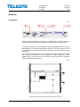
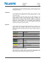
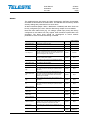
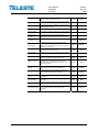
1
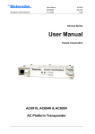
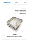
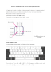
User Manual
59300235
5.4.2007
AC6951
Rev.002
1(30)
ACcess Series
User Manual
Teleste Corporation
AC6951
AC Platform Transponder
User Manual
59300235
5.4.2007
AC6951
Rev.002
2(30)
Introduction
AC6951 is an element management transponder with forward and return path
level measurement and ALSC controller unit for the AC platform. AC6951 can
be plugged into any AC platform amplifier/node equipped with compatible
transponder slot.
The transponder will be later available as HMS compatible version. With a
simple software update AC6951 can be changed to AC6951 HMS and vice
versa. Therefore all hardware related information in this manual applies to both
CATVisor and HMS versions.
VERSION INFORMATION this document is based on:
CATVisor software version
1.1
HMS software version
N/A
Hardware version
A
Viewer version
1.0
Viewer files
AC6951.DLL, FnAlarmCtrl.DLL,
FnAlarmDefsAC.txt
WEEE Notice
This product complies with the relevant clauses of the European
Directive 2002/96/EC on Waste Electrical and Electronic Equipment
(WEEE). The unit must be recycled or discarded according to
applicable local and national regulations.
European Conformity
This equipment conforms to all applicable regulations and directives
of European Union which concern it and has gone through relevant
conformity assessment procedures.
User Manual
59300235
5.4.2007
AC6951
Rev.002
3(30)
Hardware
Installation
8607012
1
2
3
4
Figure 1. AC6951 transponder front panel, 1) USB mini-B service port onnector,
2) Indicator for modem status, 3) Indicator for station status, 4) Light sensor
To install an AC6951 unit, first locate the correct installation position. Snap off
the segments of the shrouds break-away type slot cover and remove the slot
cover. Insert the unit by pressing it gently into place. The unit will fit only in one
orientation.
To carry away the heat from the unit to the housing, a silicon elastomer is used
with AC6951 transponders. After installation carefully attach the silicon
elastomer (40 x 20 mm) on the cover (see figure 2). Be sure that the elastomer
adhesive surface faces the cover.
8604092
Figure 2. Fitting of the silicon elastomer on the AC1000 cover.
User Manual
59300235
5.4.2007
AC6951
Rev.002
4(30)
In AC8000 platform a shroud is attached to the lid, to shield the electronics from
electromagnetic interference. The silicon elastomer must be attached to area
provided in the shroud.
Connectors
The transponder has an USB service port (figure 1 pos.1) connection, which
can be used for local configuration with a PC and standard USB A <=> USB
mini-B (5-pin) cable.
AC6951 transponder will draw power from the USB connector for its
microcontroller and memory if no external power supply is available. This
makes it possible to make a software download to AC6951 unit which is not
installed into any AC platform. Note that when configuring a transponder
installed into unpowered platform, some of the platform-specific parameters and
modules (e.g. optical modules) are not accessible. Some transponder
parameters will be overwritten with values on the platform memory when
transponder is installed into powered platform.
Indicators
The two LEDs on the front panel are labelled as "Station" and "Modem". The
following table further describes these indicators. During the power-up
sequence both LEDs will display yellow light for a short period of time to
indicate that LEDs are functional. See also the ‘Alarms’ chapter for details of
LED usage.
STATION LED
Description
██████████ green
No alarms other than modem related.
██████████ yellow
At least one minor alarm, no major alarms.
██████████ red
At least one major alarm.
MODEM LED
Description
Not connected, scanning for communication
channel
Not connected, communication channel found,
registering.
Connected, no modem related alarms
Connected, at least one modem related minor
alarm, no major alarms
Connected, at least one modem related major
alarm
██████████ dark
██████████ green (blinking)
██████████
green
██████████
yellow
██████████
red
Note that notifications do not affect LEDs.
When transponder is installed in platform equipped with optical receiver, it also
takes control of the receiver's LED. The LED colour is determined by the
respective alarm status, see "Alarms" chapter for more details.
User Manual
59300235
5.4.2007
AC6951
Rev.002
5(30)
Software
Establishing connection
All the needed configurations and adjustments can be carried out locally or
remotely by using the CATVisor Commander software. Detailed CATVisor
Commander hardware requirements and installation instructions can be found
from the User Manual supplied with Commander.
Connection to AC6951 is possible using the following methods:
Local configuration with PC through standard USB port
Commander 2.7 or later is needed for USB support.
Windows will ask for USB driver when connecting to AC6951 via USB for the
first time. If not found automatically, the driver can be found in 'C:\Program
Files\Common\Teleste\Drivers', select 'telestecdc.inf' file. During
the installation Windows may ask if it should stop the installation. Select
'Continue Anyway'.
Remote IP connection (AC6951 CATVisor software only)
Remote IP connection through a HEC (e.g. DMM201). Transponder IP address
has to be correctly set before remote IP communication is possible. It has to
match the subnet settings of the DMM’s HFC network interface and it must also
be unique for each transponder.
Note that it is also possible to set the IP address remotely through DMM200/201
viewer, see DMM documentation for details.
Remote SNMP connection (AC6951 HMS software only)
AC6951 HMS can be used remotely with SNMP connection through a HMTS.
Some of the communication parameters have to be set locally first.
User Manual
59300235
5.4.2007
AC6951
Rev.002
6(30)
Alarms
The module alarms, also known as "flags", displayed in CATVisor Commander
and EMS are described in the table below. The affected LED and factory default
severity settings are presented next to each alarm.
All alarm severities (Major / Minor / Notification / Disabled) and alarm limits can
be fully configured by the user. See the ‘Monitoring’ chapter for more details.
Note that some alarm limits (e.g. AC voltage, optical input power) are factory
configured so that alarms will only appear when hardware specifications are
exceeded. The alarm limits should be reconfigured to match network
parameters if more accurate monitoring is needed.
LED
Factory default
severity
Temperature is above high limit.
Station
Major & Minor
Temperature low
Temperature is below low limit.
Station
Minor
AC voltage high
Remote AC supply voltage is above high limit.
Station
Minor
AC voltage low
Remote AC supply voltage is below low limit. As some
units are equipped with mains power supply, this alarm is
disabled as factory default and should be enabled by the
user if AC voltage is to be monitored.
Station
Disabled
+24V voltage high
+24V voltage is above high limit. In AC8000 this alarm is
common for both power supplies.
Station
Minor
+24V voltage low
+24V voltage is below low limit. In AC8000 this alarm is
common for both power supplies.
Station
Major
+12V voltage high
+12V voltage is above high limit.
Station
Minor
+12V voltage low
+12V voltage is below low limit.
Station
Major
Optical Rx#1 level
high
Optical receiver #1 power level is above high limit. The
major alarm is used for controlling the optical receiver's
LED colour.
Station
Major
Optical Rx#1 level
low
Optical receiver #1 power level is below low limit. The
major alarm is used for controlling the optical receiver's
LED colour. This major alarm is also used for backup
switching logic in AC8000.
Station
Major
Optical Rx#2 level
high
Optical receiver #2 power level is above high limit. The
major alarm is used for controlling the optical receiver's
LED colour.
Station
Major
Optical Rx#2 level
low
Optical receiver #2 power level is below low limit. The
major alarm is used for controlling the optical receiver's
LED colour.
Station
Major
Optical Tx#1 laser
current high
Optical transmitter #1 laser current is above high limit.
Station
Minor
Optical Tx#1 laser
current low
Optical transmitter #1 laser current is below low limit.
Station
Minor
Optical Tx#2 laser
current high
Optical transmitter #2 laser current is above high limit.
Station
Minor
Optical Tx#2 laser
current low
Optical transmitter #2 laser current is below low limit.
Station
Minor
Unknown module
Transponder is not able recognize other module(s).
Possible reason is too old embedded software. Not
generated if transponder is powered from USB.
Station
Major
Transponder
internal error
Transponder has an internal error. If resetting the unit
does not help, it should be sent to service.
Station
Major
Lid open
Lid sensor light level has been above limit during last
minute.
Station
Notification
Alarm text
Description & suggested corrective action
Temperature high
User Manual
59300235
5.4.2007
AC6951
Rev.002
7(30)
Return path off
Return path is turned off. In AC2000 and AC8000 this
alarm is common for both return paths.
Station
Notification
Return path -6 dB
Return path is attenuated 6 dB. In AC2000 and AC8000
this alarm is common for both return paths.
Station
Notification
Settings changed
Unit's settings have been modified by user either locally or
remotely during last minute.
Station
Notification
Application started
Unit was reset or rebooted during last minute.
Station
Notification
Service terminal
connected
There has been activity on local service connector during
last minute.
Station
Notification
Modem receive
level low
RF modem receiver level is too low for reliable
communication. Generated only if modem is connected
Modem
Minor
Modem not
connected
RF modem is not communicating with HEC.
Modem
Notification
Modem transmit
level saturated
Commanded transmit level is outside dynamic range,
modem transmit level is saturated at minimum or
maximum value. Generated only if modem is connected
and minimum < maximum.
Modem
Notification
Tuner module error
Internal error in the tuner module. If resetting the unit does
not help, it should be sent to service.
Station
Major
ALSC all pilots
missing
All pilots are missing. Not generated if ALSC is switched
off.
Station
Major
ALSC saturated
ALSC is saturated, i.e. adjustment limits have been
reached. Not generated if ALSC is switched off.
Station
Minor
ALSC on 1 pilot
only
Upper/lower main and backup pilots are missing. ALSC is
controlling gain only, slope control is frozen. Not
generated if ALSC is switched off, or there is no slope
adjustment possibility.
Station
Minor
ALSC main pilot(s)
missing
One or both main pilot(s) are missing; ALSC uses backup
pilot(s). Not generated if ALSC is switched off.
Station
Notification
ALSC off
Electrical adjustment module installed but ALSC is
switched off by user. Or ALSC switched on by user but
electrical adjustment module(s) are missing.
Station
Notification
Spectrum out of
limits
Spectrum analyser measurement results are not within
high/low limits.
Station
Minor
Ingress warning
Return path ingress measurement results are above
warning limit.
Station
Minor
Ingress alarm
Return path ingress measurement results are above alarm
limit.
Station
Major
Powered from USB
Transponder powered from USB, platform is not powered.
Connect power to platform power supply for full
functionality.
Station
Notification
User Manual
59300235
5.4.2007
AC6951
Rev.002
8(30)
Viewer pages
Some configuration display (=”viewer”) pages are always visible, some pages
are visible only with specific platform / module configurations.
AC6951 viewer pages:
− Status
− Configuration
− Optical (visible with AC8000, AC800 and AC500/1000/2000 equipped with
optical module(s))
− Levels
− Transponder (separate pages for CATVisor and HMS transponders)
− SNMP (visible with HMS transponder)
− Monitoring
− Spectrum
− Ingress (visible with platforms supporting return path measurement)
− Repair log
− Properties
Some viewer pages have fields with colored background, e.g. "Temperature" on
"Configuration" page. These colours indicate the alarms related to this field.
Green means no alarms or notifications; red is major alarm, yellow is minor
alarm and blue is notification.
User Manual
59300235
5.4.2007
AC6951
Rev.002
9(30)
Status
Figure 3. The Status page
The Status page shows unit's present status and possible alarms (="flags").
Each alarm is colour coded according to its severity. The severities can be
configured through "Monitoring" viewer page. For additional information about
alarms, see table of module alarm descriptions in the "Alarms" chapter.
It is possible to hide the less critical flags by checking the corresponding check
box for warnings or notifications. Note that these selections only hide flags
from this viewer page; the device still generates the alarms. Use "Monitoring"
viewer page to configure alarm severities.
User Manual
59300235
5.4.2007
AC6951
Rev.002
10(30)
Configuration
Figure 4. The Configuration page (AC1000 shown)
The “Configuration” page displays a graphical view of the current configuration
similar to the actual station layout, allows return path ingress switch control and
displays measurement data.
Station layout
Most active plug-in modules are detected automatically by the transponder.
They are presented as grey boxes.
The (passive) modules and plugs, e.g. fuses, cannot be detected automatically.
These are presented with blue texts. Selecting a text tag representing a passive
device will open a pull down selection list in which an appropriate device
according the assembly can be selected. The user can also type in the desired
information (up to 12 characters, 6 characters for fuses). These passive devices
do not have any monitoring or control parameters, and the information entered
in these fields does not affect unit operation in any way, it's just a "checklist".
Return path
The “Return path” frame consists of three radio buttons which control the
ingress switch. Note that the incoming return path RF signal will be completely
cut off by the “Off” selection and will thus also disconnect all other transponders
behind this station. In AC2000 and AC8000 platforms there are two
independent return path controls.
Measurements
The background colour of each field shows the parameter's alarm status. Alarm
limits and severities can be configured through "Monitoring" page.
The "Voltages" frame displays measured supply voltages of the station.
The “AC voltage” field shows true RMS value (DC+AC component) of the
remote supply voltage. This value is calculated using sliding average and thus
User Manual
59300235
5.4.2007
AC6951
Rev.002
11(30)
will react quite slowly to changes. The factory default limit values are based on
power supply specifications and are thus quite broad. They should be adjusted
to match the network's AC supply voltages if accurate monitoring is needed.
+12 V and +24 V factory default alarm limits are based on power supply
specifications and usually shouldn't be altered. AC8000 has two +24 V fields as
it can be equipped with double power supplies. If only one power supply is
installed, the corresponding low voltage alarm limits should be set to zero to
avoid false alarms. It is possible to connect one external voltage or alarm line to
AC8000 and monitor its status through "+24 V #2" field instead of the second
PSU's +24 V voltage.
The temperature display is based on AC6951's internal sensor. Temperature
factory default alarm limits are defined separately for each platform based on
their average power consumption.
The “Service terminal” field shows "ON" if there has been activity on the local
USB service connector during the last minute.
Lid status information is based on a light sensor in the transponder's front panel.
"Lid open" is displayed if light level has been above limit during the last minute.
In dark environment "Lid closed" may be displayed even if the lid is open.
User Manual
59300235
5.4.2007
AC6951
Rev.002
12(30)
Optical
This page is visible with AC8000 and AC800 platforms and with AC500 and
AC1000 platforms equipped with optical module(s).
Figure 5. The Optical page (AC8000 version)
The "Optical" page displays information on installed optical modules and allows
return transmitter pilot control and backup switching control in AC8000. The
page is slightly different in AC500, AC800 and AC1000 viewers.
Input selection (AC8000)
When “Automatic” is selected, AC8000 switches to receiver 2 if receiver 1 is not
installed or its optical input power is below low alarm limit. When receiver 1
optical input power exceeds low alarm limit + deadband, AC6951 switches back
to receiver 1. The alarm limits and deadband can be configured through
"Monitoring" viewer page.
When “Automatic (manual restore)” is selected, the backup switching takes
place in the same way as described above but AC6951 will not switch back to
receiver 1 even if its optical input power is restored. The user has to reset the
switch back to the main input by manually selecting ”Manual: Rx #1” and after
that ”Automatic (manual restore)” again.
The active receiver can also be selected manually with “Manual: Rx#1 / 2” radio
buttons.
Return transmitters (AC8000)
When the “Return transmitters” selection is set to “Both transmitters on”, both
optical transmitters are forced to be active regardless of the receiver selection.
When “One transmitter on, follows active receiver” is selected, only one
transmitter will be active and it will automatically follow the selected receiver
(i.e. receiver 1 selected => transmitter 1 on, transmitter 2 off. receiver 2
selected => transmitter 1 off, transmitter 2 on). If transmitter 2 is not installed,
transmitter 1 is always active.
User Manual
59300235
5.4.2007
AC6951
Rev.002
13(30)
Receiver modules
The type of the receiver module as well as the measured optical input level is
displayed in the “Receiver modules” frame. The “Active” radio button indicates
which receiver module is in use.
Transmitter modules
The installed transmitter modules as well as the measured laser currents are
shown in the “Transmitter modules” frame.
The “Transmitter modules” frame includes also a “Pilot” check box that controls
whether the transmitter module generates a pilot signal or not. The pilot signal
frequency (4.5 MHz or 6.5 MHz) can be selected with a DIP switch on the
transmitter module’s front panel.
User Manual
59300235
5.4.2007
AC6951
Rev.002
14(30)
Levels
This page is visible with AC platforms equipped with AC6170, AC6173, AC6174
or AC6175 gain / slope control module(s).
Figure 6. The Level control page (AC1000 version shown)
The RF level measurement unit of AC6951 sequentially measures signal levels
at user defined frequencies and, if enabled, also the forward path spectrum and
return path ingress frequencies. If ALSC adjustments are needed more priority
is given to pilot measurements.
ALSC (Automatic Level and Slope Control) keeps the output signal level stable
irrespective of input signal level variations by adjusting the AC617x gain / slope
control module(s) based on the pilots. Gain and slope are adjusted slowly in
small steps to prevent oscillation in long amplifier cascades. If gain or slope is
adjusted against the limit, AC6951 gives "ALSC saturated" alarm.
If high or low main pilot is lost, i.e. its level falls below "Lost level", AC6951 uses
the reserve pilot for ALSC and gives "ALSC main pilot(s) missing" alarm.
AC1000 and AC2000 have both high and low pilots. The high pilot controls the
gain and the low pilot controls the slope. If both high main and high reserve or
both low main and low reserve pilots are lost, AC6951 gives "ALSC on 1 pilot
only" alarm, freezes slope control and controls gain with the remaining pilot.
AC800 and AC8000 have only high pilots and thus no slope control possibility.
AC500 does not support ALSC, thus the page is slightly different.
Pilot table
Each pilot signal is displayed in the table with the following information:
Pilot name: Icon and pilot name colour coding indicates pilot status:
red for pilot lost.
green for pilot OK,
Frequency (MHz): Pilot signal frequency, adjustable in 0.25 MHz steps.
Type: Detector type. The measurement detector can be individually selected
for each frequency between peak detect (“Analog”) and averaging (“QAM”).
User Manual
59300235
5.4.2007
AC6951
Rev.002
15(30)
Measured (dBµV): Measured level of pilot signal.
Target (dBµV): Pilot signal target level for ALSC operation.
Lost level (dBµV): Limit below which the pilot is considered as lost.
Usage: Usage status of the pilot signal. ALSC / Standby / Not used.
The pilot signal frequency, detector type, target level and lost level can be
configured by double-clicking a row in pilot table. This will open a dialog box
with pilot's properties that can be edited by users with at least "Service" level
user rights. For others this is read-only information. "Apply" button is needed
after all pilot settings have been configured.
Figure 7. The pilot signal configuration dialog box
ALSC
The “ALSC enabled” is the master switch of ALSC (Automatic Level and Slope
Control) functionality. In addition to this selection, ALSC also needs appropriate
electrical adjustment module(s) installed for correct operation.
ALSC
enabled
Yes
Yes
No
No
Adjustment
module(s)
Installed
Not installed
Installed
Not installed
ALSC
works
Yes
No
No
No
ALSC related alarms
Enabled
"ALSC off" alarm. Other alarms disabled
"ALSC off" alarm. Other alarms disabled
Alarms disabled
The data field next to checkbox displays the ALSC status:
−
−
−
−
−
−
"ALSC on" (green); ALSC is enabled and works properly.
"ALSC off" (blue); ALSC is disabled by user.
"Tuner module error" (red); Error in AC6950’s tuner module, ALSC disabled.
"ALSC all pilots missing" (red); All pilots are missing.
"ALSC saturated" (yellow); ALSC is saturated (=adjustments limits reached).
"ALSC on pilot 1 only" (yellow); Upper or lower main and reserve pilots are
missing, ALSC controls gain only, and slope control is frozen.
− "ALSC main pilot(s) missing" (blue); Main pilot(s) missing; ALSC uses
reserve pilot(s).
− "No interstage module" (grey); No interstage module installed.
All pilots lost action
When all pilots are lost, AC6951 gives "ALSC all pilots missing" alarm and
operates as selected by "All pilots lost action" radio buttons:
User Manual
59300235
5.4.2007
− Freeze controls:
− Go to:
AC6951
Rev.002
16(30)
Gain and slope controls will keep the values they
had immediately before the pilot signals were lost.
Gain and slope controls will slowly step to user
defined values in the “Gain” and “Slope” edit fields.
Notice
The "Notice" field from "Repair log" viewer page is shown as read-only on the
bottom of "Levels" page, allowing the field to be used e.g. as a reminder for the
pilot settings.
Input stage
The input module type is shown on the top of this frame.
The "Gain" and “Slope” fields and up and down buttons can be used to control
the level values in 0.2 dB steps when ALSC is disabled. When ALSC is enabled
it has the control and this field is read-only with background colour indicating
ALSC status. In AC800 equipped with AC6170 input module the slope control is
not supported.
OLC in AC800
In AC800 it is possible to use OLC (Optical Level Control) if AC6173 module is
installed into input module slot. There are two radio buttons, "Manual" and
"From optical input level" in the "Input stage" frame.
OLC can be enabled by selecting "From optical input level". It changes "Level
control" field to read-only and adjusts input level control based on the optical
input level to keep AC800's internal amplifier input signal level at its optimum
value. At input levels < -5 dBm the input level control is 0 dB, above this each 1
dBm increase in optical input level causes level control to go down 2 dB. For
input levels > 0 dBm the level control will be -10 dB. The level control
adjustment deadband is fixed at 0.5 dB, i.e. changes less than this value will not
be corrected. OLC will react instantaneously to changes, i.e. it does not have
"stepping" feature as in ALSC.
Interstage
The interstage module type is shown on the top of this frame.
The "Gain" and “Slope” fields and up and down buttons can be used to control
the level value in 0.2 dB steps when ALSC is disabled. When ALSC is enabled
it has the control and this field is read-only with background colour indicating
ALSC status.
AC800 and AC8000 differences
The "Levels" pages of AC800 and AC8000 are essentially the same than in
AC500, AC1000 and AC2000. As there is no need for slope adjustment in these
nodes, there are no low pilots and no slope controls.
AC2000 and AC8000 second outputs
AC2000 and AC8000 platforms have dual outputs, but ALSC only measures
output 1. In AC8000, output 2 level automatically follows output 1 changes, with
the offset specified in the "Gain offset to output 1" edit field.
In AC2000 output 2 slope is adjusted according to output 1 slope with the offset
specified in "Slope offset" edit field.
User Manual
59300235
5.4.2007
AC6951
Rev.002
17(30)
Transponder (CATVisor)
This page is visible with CATVisor transponder.
Figure 8. The Transponder (CATVisor) page
The “Transponder” page displays all the data and settings of the transponder’s
RF modem and remote communication. After reset the unit starts searching for
HEC (headend controller, e.g. DMM201) carrier within the transponder’s tuning
range and starts communicating. The HEC will then set communication
parameters such as transmitter frequency and transmitter level.
Connection status
The current communication status between the transponder and HEC is shown
in the “Connection status” field with
−
−
−
−
“Scanning” (yellow); searching for the HEC carrier wave.
“Data carrier found” (yellow); waiting for communication parameters.
“Registering” (yellow); registration in progress.
“Connected” (green); registration complete, communication OK.
The number in parenthesis is a more detailed status indicator for diagnostics
purposes, ranging from 0 to 11.
Receiver
The “Frequency” data field shows the used receiver frequency.
The “Level” data field shows the measured signal level.
The “Scan start” and “Scan stop” fields determine the frequency band that the
unit scans through when searching for the HEC carrier. Scanning can be
disabled by setting the start and stop frequencies to the same value. Scanning
speed can be improved by limiting the scanning range. The default and
maximum range is 80…155 MHz. The scan will start from the last known HEC
carrier frequency.
User Manual
59300235
5.4.2007
AC6951
Rev.002
18(30)
The “Scan step” field sets the frequency increments of the scanning process,
default and minimum value is 0.1 MHz.
Changing any of these fields will reset RF modem communication.
Transmitter
The “Frequency” data field shows the used transmitter frequency commanded
by the HEC. The “Level” data field shows the transmitter signal level.
The range for transmit signal level can be set in the “Min level” and “Max level”
fields. The default and maximum range is 75…100 dBμV. If the HEC commands
transponder to use transmit level outside this range, nearest allowed value is
used and "Modem transmit level saturated" alarm is activated.
Changes in these values will not reset RF modem communication and will be
taken into use immediately if HEC’s ALC is enabled.
Communication settings
The “IP address” field is used to define the IP address of the unit. The address
has to be unique and match the HEC’s IP subnet settings to ensure proper
operation and IP level communication with the HEC.
If the IP address is set incorrectly, e.g. 0.0.0.0, the transponder can still
communicate with the HEC on MAC level, but IP traffic (i.e. viewer / EMS
messages) is not possible. It is however possible to set the IP remotely through
DMM20x viewer.
The “Net mask” field defines the corresponding IP subnet. It is only needed for
broadcast software updates and has to be set according to the HFC subnet of
the HEC; otherwise it can be left as 255.255.255.255.
The “MAC address” is the unit’s unique, read-only hardware address that is also
printed on the front panel sticker of AC6951.
Manageable devices in the same HFC network can be divided into different
device groups. The “Device group” check boxes can be used to group
transponders under multiple HECs. For more information, consult DMM20x user
manual.
Changing any of these fields will reset RF modem communication.
Packet statistics
The “Received” field displays the total number of IP packets addressed to and
received by this unit.
The “Sent” field displays the total number of IP packets sent by this unit.
The “Bad” field displays the number of all bad packets received (whether
addressed to this unit or not) and is a good indicator of the forward path
condition.
All statistics field counters has limited range [0…65536], so they will wrap
around when maximum number of packets is reached. Thus absolute values of
counters are not meaningful.
The "Reset" button will reset all packet counters to zero.
User Manual
59300235
5.4.2007
AC6951
Rev.002
19(30)
Monitoring
Figure 9. The Monitoring page
The "Monitoring" page displays all monitored parameters and their values as
well as alarm limits, statuses and severity settings.
See "Alarms" chapter for descriptions of individual AC6951 alarms.
Analog parameters
Each monitored analog parameter of the unit is displayed in the upper half of
the frame with following information in the list:
Analog parameter: Name of the monitored parameter.
Alarm: Alarm status of the parameter: No / HIHI / HI / LO / LOLO
Value: Current measured value.
HIHI: High major alarm limit
HI: High minor alarm limit.
LO: Low minor alarm limit
LOLO: Low major alarm limit.
Deadband: Specifies how much the measured value has to be on the "safe"
side of alarm limit before turning off the alarm.
Unit: Unit of the measured parameter.
User Manual
59300235
5.4.2007
AC6951
Rev.002
20(30)
The colour of each list entry and the icon next to parameter name indicates
alarm status:
-
green for nominal value
-
red for major alarm
-
yellow for minor alarm
-
grey for disabled alarm
The alarm settings are user configurable by double-clicking an analog
parameter. This will open a dialog box with parameter's alarm limits and
deadband that can be edited by users with at least "Service" level user rights.
For others this is read-only information.
Figure 10. The analog alarm configuration dialog box
Each alarm limit can be individually enabled/disabled and configured. The alarm
limits should be in decreasing order for correct alarm processing, preferably
with more than "Deadband" units between each limit.
Discrete parameters
Each monitored discrete parameter of the unit is displayed in the lower half of
the frame with following information in the list:
Discrete parameter: Name of the monitored parameter.
Alarm: Alarm status of the parameter: No / Notification / Minor / Major. If the
alarm is disabled, but parameter is in alarming state, "Yes" is shown.
Setting: Alarm severity can be configured to Major, Minor, Notification or
Disabled.
The colour of each list entry and the icon next to parameter name indicates
alarm status:
-
green for nominal value
-
red for major alarm
-
yellow for minor alarm
-
blue for notification
-
grey for disabled alarm
User Manual
59300235
5.4.2007
AC6951
Rev.002
21(30)
The alarm severity setting is user configurable by double-clicking a discrete
parameter. This will open a dialog box which can be edited by users with at
least "Service" level user rights. For others this is read-only information.
Figure 11. The discrete alarm configuration dialog box
Alarm control
Alarm control frame provides independent on-delay and off-delay timers. The
time delay feature can be used to eliminate false alarm triggering due to
momentary disturbances. An alarm is only active when “Detection” is enabled
and the monitored parameter has been over limit longer than "Delay On" time.
Alarm goes off when the parameter has been inside limits longer than "Delay
Off" time.
The settings on the “Alarm control” frame can be edited by a user with at least
Service level user rights. For others this is read-only information. It is
recommended not to change these values from their factory default value 1 s
without fully understanding the effects on EMS system performance.
Alarm log
Clicking the "Alarm log" button on "Monitoring" page opens alarm log dialog.
Figure 12. The Alarm log dialog
The “Alarm log” dialog box displays the alarm history for latest 32 events. The
list is stored in non-volatile memory. All entries are date and time stamped with
the most current entry at the bottom. Note that date/time information may not be
correct for events that occurred before latest reset.
User Manual
59300235
5.4.2007
AC6951
Rev.002
22(30)
The icon and colour of each list entry indicates alarm status:
-
green for nominal value
-
red for a major alarm
-
yellow for a minor alarm
-
blue for a notification
The total number of entries in the alarm log list is shown in the “Number of
entries” field. The index number of the last entry is displayed in the
accompanying field. Total number of entries is limited to 32. The oldest entry is
overwritten when the log becomes full.
To update “Alarm log” page, click the “Refresh” button.
“Clear and regenerate log” button clears alarm log and restarts alarm detection.
User Manual
59300235
5.4.2007
AC6951
Rev.002
23(30)
Spectrum
Figure 13. The Spectrum page
The "Spectrum" viewer page presents forward path level measurements in a
graphical “spectrum analyser” display. Up to 100 measurement frequencies with
individual PAL / QAM selection and high / low limits can be specified with a
simple text file. The measurement results can also be saved back to a text file.
Display settings
When the viewer page is opened, the measurement results are retrieved from
the device and displayed. The display is automatically scaled so that all
measured frequencies are visible and the level scale is set to 10 dB/div. The
display can then be zoomed or re-centered by entering new values into start
and stop frequency, reference level and scale dialogs and clicking “Redraw”
button. The "Fit view" button scales the display so that all measurement
frequencies are visible; "Reset view" button restores full-scale display.
The RBW (resolution bandwidth) is fixed to 1.5 MHz by the hardware.
The "Sweep" field displays the last elapsed time it took to scan through the
complete set of measurement frequencies.
The “De-sloped view” drop-down box can be used to simulate a view of a flat
frequency response by reducing the level at the high end of the amplifier’s
response. Signal level at 862 MHz is displayed with the attenuation specified in
"De-sloped view", signal level at 47 MHz is not affected at all and attenuation of
the frequencies between these two are calculated using a standard coaxial
cable model. The “De-sloped view” function acts only as a visual aid for making
adjustments and does not affect device operation in any way.
If the graphical display is clicked with mouse the frequency, measured level,
detector mode and possible high / low limit values of the clicked measurement
are displayed next to the clicked point.
User Manual
59300235
5.4.2007
AC6951
Rev.002
24(30)
Limits
The “Limits” group box has two selections. When "Show" is checked the low
and high limit(s) for each measurement frequency are shown in the graphical
display with blue and red triangles, respectively. If a measurement is over high
limit, it will be drawn in red; if it is below low limit, in blue, otherwise in black.
The "Tolerance" field specifies how many spectrum measurements are allowed
to be outside limits before the "Spectrum out of limits" alarm is generated. The
default value 0 will generate the alarm even if only one value is outside limits.
"Tolerance" allows fine-tuning the limit testing so that e.g. it doesn't react to one
missing TV channel. The alarm is set or cleared at the end of each
measurement cycle.
Analyser settings
The “Analyser ON” checkbox is the main switch for the spectrum analyser
feature. When checked, AC6951 will cyclically measure the frequencies
specified in the sweep file, in addition to the standard four pilots measurements
and possible return path ingress measurements. AC6951 typically measures
more than 10 frequencies per second, depending on the amount of ALSC
adjustments needed during the sweep.
The “Restart sweep” button clears the measurement results table and restarts
the sweep.
The “Current sweep file” field displays the filename of the last sweep file
downloaded to the device. This name is derived from the first 15 characters of
the file name.
The “File >> Device” and “Device >> File” buttons open a file dialog for
transferring a sweep / result file to / from the device.
Sweep and result file formats
The sweep file is a simple text file than can be edited with any text editor and
most spreadsheet applications. Each line in the sweep file defines one
measurement frequency, preferably in ascending order. Each line has 2-4 fields
separated with tab characters and dot (.) as the decimal separator:
1. The measurement frequency in multiples of 0.25 MHz.
2: The detector mode as “P” or “PAL” for peak detection or “Q” or “QAM” for
averaging measurement. Detector mode designation is not case sensitive.
3: Optional low limit in multiples of 0.5 dBμV.
4: Optional high limit in multiples of 0.5 dBμV.
Comments can be inserted at the end of the line, preceded with a tab character,
or on a separate row which starts with a non-numeric character. Comments are
for information only and will not be downloaded into the device and so they are
lost if result table is uploaded back from device.
An example of a valid sweep file:
113
121.00
126.25
133.25
QAM
Q
P
PAL
98.0
95
103.5
101
Channel S2
Channel S3
Another comment
User Manual
59300235
5.4.2007
AC6951
Rev.002
25(30)
The result file format is identical to the sweep file format, except that it has a
header row and a 5th column which contains the measurement results. An
example of a result file produced by the above sweep file could be like this:
MHz
113.00
121.00
126.25
133.25
Type
Q
Q
P
P
LoLimit HiLimit dBµV
98.0
103.5
100.5
101
99.5
101
95
98
User Manual
59300235
5.4.2007
AC6951
Rev.002
26(30)
Ingress
This page is visible in platforms supporting return path ingress measurement.
Figure 14. The Ingress page
The "Ingress" viewer page presents return path measurements in a graphical
“spectrum analyser” display when used with AC station supporting return path
measurement. Up to 100 measurement frequencies with individual PAL / QAM
selection and alarm / warning limits can be specified with a simple text file. The
measurement results can also be saved back to a text file.
Display settings
When the viewer page is opened, the measurement results are retrieved from
the device and displayed. The display is automatically scaled so that all
measured frequencies are visible and the level scale is set to 10 dB/div. The
display can then be zoomed or re-centered by entering new values into start
and stop frequency, reference level and scale dialogs and clicking “Redraw”
button. The "Fit view" button scales the display so that all measurement
frequencies are visible; "Reset view" button restores full-scale display.
The RBW (Resolution BandWidth) is fixed to 1.5 MHz by the hardware. Note
that due to the roll off of the RBW filter, a payload-free area is needed if noise
levels need to be measured.
The "Sweep" field displays the last elapsed time it took to scan through the
complete set of measurement frequencies.
If the graphical display is clicked with mouse the frequency, measured level,
detector mode and possible alarm / warning limit values of the clicked
measurement are displayed next to the clicked point.
Return amplifier selection and ingress switch
Correct return amplifier type must be selected in the "Return amplifier" dropdown in order to get correct measurement results. AC6951 then adjusts the
measurements results to compensate for the different gain of different return
amplifier types. Some return amplifier types are not supported.
User Manual
59300235
5.4.2007
AC6951
Rev.002
27(30)
Note that the ingress switch position is not taken into account in ingress
measurement. Thus selecting -6 dB ingress switch will result in 6 dB decrease
in measured ingress levels.
Limits
The “Limits” group box has two selections. When "Show" is checked the alarm
and warning limit(s) for each measurement frequency are shown in the
graphical display with red and blue triangles, respectively. If a measurement is
over alarm (HIHI) limit, it will be drawn in red; if it is over warning (HI) limit but
not over alarm limit, in blue, otherwise in black.
The "Tolerance" field specifies how many ingress measurements are allowed to
be over limits before the "Ingress warning" and "Ingress alarm" alarms are
generated. The default value 0 will generate the alarm even if only one value is
over limit. The alarms are set or cleared at the end of each measurement cycle.
Analyser settings
The “Analyser ON” checkbox is the main switch for the ingress measurement
feature. When checked, AC6951 will cyclically measure the frequencies
specified in the sweep file, in addition to the standard four pilot measurements
and possible forward path spectrum measurements. AC6951 typically measures
more than 10 frequencies per second, depending on the amount of ALSC
adjustments needed during the sweep.
The data field next to “Analyser ON” check box displays the ingress status:
-
“Ingress OK” (green)
“Ingress alarm” (red)
“Ingress warning” (yellow)
"Ingress disabled” (grey)
The “Restart sweep” button clears the measurement results table and restarts
the sweep.
The “Current sweep file” field displays the filename of the last sweep file
downloaded to the device. This name is derived from the first 15 characters of
the file name.
The “File >> Device” and “Device >> File” buttons open a file dialog for
transferring a sweep / result file to / from the device.
Sweep and result file formats
The sweep file is a simple text file than can be edited with any text editor and
most spreadsheet applications. Each line in the sweep file defines one
measurement frequency, preferably in ascending order. Each line has 2-4 fields
separated with tab characters and dot (.) as the decimal separator:
1. The measurement frequency in multiples of 0.25 MHz.
2: The detector mode as “P” or “PAL” for peak detection of return path payload
signals or “Q” or “QAM” for averaging measurement of return path ingress
noise. Detector mode designation is not case sensitive.
3: Optional warning limit in multiples of 0.5 dBμV.
4: Optional alarm limit is in multiples of 0.5 dBμV.
Comments can be inserted at the end of the line, preceded with a tab character,
or on a separate row which starts with a non-numeric character. Comments are
for information only and will not be downloaded into the device and so they are
lost if result table is uploaded back from device.
User Manual
59300235
5.4.2007
AC6951
Rev.002
28(30)
An example of a valid sweep file:
Measures return
5.00
Q
7.50
Q
10.00
Q
12.50
Q
15.00
Q
path lowest frequencies
35.0
40.0
Comment
35.0
40.0
Another comment
35.0
40.0
35.0
40.0
35.0
40.0
The result file format is identical to the sweep file format, except that it has a
header row and a 5th column which contains the measurement results. An
example of a result file produced by the above sweep file could be like this:
MHz
5.00
7.50
10.00
12.50
15.00
Type
Q
Q
Q
Q
Q
HiLimit
35.0
35.0
35.0
35.0
35.0
HIHILimit
dBµV
40.0
48.0
40.0
49.0
40.0
44.5
40.0
44.0
40.0
29.5
User Manual
59300235
5.4.2007
AC6951
Rev.002
29(30)
Repair log
Figure 15. The Repair log page
The “Repair log” page can be used to store information about eventual repair
events into the transponder’s non-volatile memory. This information may then
be used e.g. for statistical purposes.
Repair List
The “Repair events” maintains a brief list of repair notes the user can add with
the application. The repair list contains 10 of the operator’s recently added
notes. The date of the service can be selected from the pull-down list. The
repair code and the name code can be entered in the edit boxes next to the
pull-down list. Clicking “Add” adds these notes to the list. New item is added to
the top of the list.
Notice
“Notice” is a text entry field where a message can be left e.g. for the next
service technician. The message can contain up to 100 characters. Clicking the
“Clear” button clears this text entry field. The notice text is also shown on the
"Levels" page, allowing the field to be used e.g. as a reminder for pilot settings.
User Manual
59300235
5.4.2007
AC6951
Rev.002
30(30)
Properties
Figure 16. The Properties page
The “Properties” page displays unit identification and statistics data.
Station
The user can enter a descriptive alias name for the station into the “Name” field,
such as site location etc. Alias name can contain up to 63 alphanumeric
characters.
The type and serial number of the station are read-only information.
Transponder
The type and hardware version of the transponder unit as well as the serial
number and the software version are read-only information.
Statistics
The “Uptime” field shows the time since the last reset or power up. The format
is days, hours, minutes and seconds, with ±5 s/day accuracy.
The "Total uptime" field shows the total number of full operating days of the
transponder. The "Reset count" field shows the total number of transponder
resets.