1
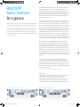
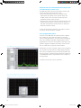
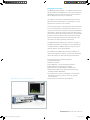
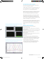
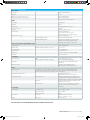
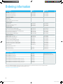
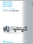
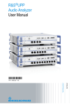
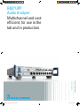
UPPx_bro_en_5214-3846-12_v0300.indd 1 Product Brochure | 03.00 Test & Measurement R&S®UPP Audio Analyzer Multichannel and costefficient, for use in the lab and in production 11.12.2013 07:48:56 R&S®UPP Audio Analyzer At a glance High measurement speed, parallel signal processing in multichannel applications, and high reliability in continuous operation are vital requirements to be met by audio analyzers for use in production. If, on top of that, a cost-efficient instrument for system use is what you need, the solution is the R&S®UPP audio analyzer. The R&S®UPV audio analyzer – the high-end instrument from Rohde & Schwarz – has held a solid position in all audio T & M applications for years. Measurement accuracy and dynamic range at the limits of what is possible, combined with unique measurement capabilities, make the R&S®UPV ideal primarily for research, development and quality assurance tasks. Many audio applications do not place such high requirements on dynamic range and versatility. The emphasis in production is often on high throughput, and the cost of production test assemblies also plays a major role. When testing consumer audio equipment, multichannel devices of surround sound systems must also be measured using state-of-the-art interfaces such as HDMI® 1). This is where the R&S®UPP audio analyzer family comes into its own. Depending on the model, two, four or eight channels are processed in parallel; and by cascading multiple instruments, users can simultaneously trigger up to 48 measurement channels, which cuts down on measurement time. The compact, cost-efficient R&S®UPP audio analyzer is designed for system applications. It features low height, and comes without front-panel control elements or integrated display. The instrument can be remote controlled via LAN, USB or IEC/IEEE bus. In combination with an external monitor, mouse and keyboard, it becomes a manually operable measuring instrument for a lab bench. It has an integrated control PC, and the required software is already installed. Users can start taking measurements right away. Featuring the same operating philosophy and remote control, the R&S®UPV and R&S®UPP audio analyzers are a strong team: They provide the optimal solution for both R & D and production and harmonize well together, for example when instrument settings or measurement routines have to be exchanged. 1) HDMI® is a registered trademark of HDMI Licensing, LLC. Key facts ❙ ❙ ❙ ❙ ❙ R&S®UPP200 with R&S®UPP-B2 option. Suitable for all interfaces: analog, digital and combined Parallel measurements on up to eight channels Up to 80 kHz bandwidth and 200 kHz sampling rate User-programmable filters for analyzer and generator Compact instrument with integrated PC and low height R&S®UPP400 with R&S®UPP-B2 option. 2 UPPx_bro_en_5214-3846-12_v0300.indd 2 11.12.2013 07:48:56 R&S®UPP Audio Analyzer Benefits and key features Large variety of interfaces in a single instrument ❙❙ Two-, four- or eight-channel analyzer with analog inputs ❙❙ Analog generator outputs (two-channel) ❙❙ Eight-channel generator (R&S®UPP-B8 option) ❙❙ AES/EBU and S/P DIF interfaces for measuring digital audio components (R&S®UPP-B2 option) ❙❙ I²S interfaces for testing audio ICs (R&S®UPP-B2/-B4 option) ❙❙ HDMI device testing (R&S®UPP-B4 option) ❙❙ Interfaces for the generator and analyzer can be set independently of one another and used together in any combination ▷▷ page 10 Powerful and fast ❙❙ Parallel measurements for high throughput ❙❙ High measurement speed throughout the system ❙❙ Ideal for use in production ❙❙ Multichannel measurements by means of cascading ▷▷ page 4 All test signals and measurement functions in a single box ❙❙ Generation of a wide variety of analog and – with the R&S®UPP-B2/-B4/-B8 option – also digital test signals ❙❙ Broad scope of measurements on both analog and – with the R&S®UPP-B2/-B4 option – digital interfaces ❙❙ Powerful and even multichannel FFT analysis with resolution down to below 1 Hz ❙❙ User-programmable filters that can be adapted in seconds to the individual measurement task ❙❙ Integrated control PC; manual operation requires only an external monitor and a mouse and keyboard ▷▷ page 6 Convenient operation throughout ❙❙ State-of-the-art and intuitive user interface makes operation quick and easy to learn ❙❙ All measurement results at a glance ❙❙ Effective online help functions ▷▷ page 16 Options for further applications ❙❙ R&S®UPP-B2 option providing digital audio interfaces in line with AES/EBU and S/P DIF as well as I²S interfaces ❙❙ R&S®UPP-K21 digital audio protocol ❙❙ R&S®UPP-B4 HDMI and digital audio interfaces ❙❙ R&S®UPP-K41 Dolby® decoding 1) ❙❙ R&S®UPP-K45 extended audio/video measurements ❙❙ R&S®UPP-K601 1/n octave analysis ❙❙ R&S®UPP-K800 cascading software for combining multiple R&S®UPP audio analyzers for parallel measurement of more than eight channels ❙❙ XLR/BNC adapter sets ❙❙ Connecting cables for analog and digital interfaces ❙❙ R&S®UPZ audio switcher for switching input and output channels ▷▷ page 18 Dolby® is a registered trademark of Dolby Laboratories. 1) R&S®UPP800 with R&S®UPP-B4 option. UPPx_bro_en_5214-3846-12_v0300.indd 3 R&S®UPP800 with R&S®UPP-B8 option. Rohde & Schwarz R&S®UPP Audio Analyzer 3 11.12.2013 07:48:58 Powerful and fast Parallel measurements for high throughput The R&S®UPP performs all measurements, including FFT analyses with maximum resolution, on all channels simultaneously. With multichannel measurements, this considerably reduces the overall measurement time compared with instruments that can only process two channels at a time by using an audio switcher, for example. By cascading multiple R&S®UPP audio analyzers, simultaneous measurements can be expanded to cover up to 48 channels (see following page). Since each instrument has its own integrated PC, there is sufficient computing power available so that no time is lost even when analyzing a large number of parallel channels. High measurement speed throughout the system High measurement speed, multichannel measurements and remote control capability are indispensable in production lines. The long calibration intervals of the R&S®UPP ensure high availability and reduce operating costs. The R&S®UPP audio analyzer was designed with a focus on maximizing the speed of the overall measurement system: ❙❙ Time-critical and computation-intensive process steps are carried out directly in the R&S®UPP audio analyzer by digital signal processors and the integrated PC. Raw data does not have to be exported to the test system's controller for analysis, so no additional computing time is required and unnecessary transmission time is avoided ❙❙ Digitally implemented analysis functions optimally adjust the measurement time to the measurement task. For example, the measurement time is adjusted to the frequency of the test signal – not only for level measurements but also for complex analyses such as the THD+N measurement – in order to minimize the measurement time ❙❙ The internal setting and settling times in the generator and the analyzer are optimized using digital signal processing; they are also taken into account in the measurement routines, thereby yielding stable results without the need to activate a settling function, which means repeating the measurement until a result within a tolerance band is obtained ❙❙ The fast frequency response measurement implemented by means of a fast Fourier transform (FFT) provides a critical edge particularly during this highly time-critical measurement (example: measurement of a frequency response with approx. 900 frequency values in 150 ms) 4 UPPx_bro_en_5214-3846-12_v0300.indd 4 11.12.2013 07:49:02 Ideal for use in production Test equipment for use in production must also meet further requirements: ❙ Long-life components designed for continuous operation keep the failure rate low in everyday production. Thousands of Rohde & Schwarz audio analyzers have already proven their reliability in this regard ❙ Long calibration intervals due to the largely digital implementation of measurement functions also contribute to high instrument availability ❙ Remote control capability is indispensable in large production facilities. In the R&S®UPP audio analyzer, special attention was also paid to maximizing the speed of data transfer via all supported interfaces (IEC/IEEE bus, USB, LAN) ❙ Easy, efficient creation of remote control routines was also a major consideration. The SCPI recording function eliminates the need to look up remote control commands and, in turn, avoids errors in programming. Measurement routines can be simplified by using limit-check or S/N measurement functions in the audio analyzer, so that no effort has to be put into programming such routines in the controller Multichannel measurements by means of cascading Elaborate sound systems in motor vehicles use amplifiers with 16 or more channels to transmit surround sound in the best possible quality via numerous loudspeakers. For applications of this kind, in which the R&S®UPP800's eight measurement channels do not suffice, several audio analyzers can be cascaded to measure all channels simultaneously, which saves time. The R&S®UPP-K800 control software turns one of the R&S®UPP800 audio analyzers into the cascade master. Up to five other R&S®UPP analyzers can be combined with this instrument as slaves. In remote control mode, for example in a production system, the entire cascade acts as a single measuring instrument with the required number of measurement channels. Therefore, only the master unit is remote controlled; it triggers all participating measurement channels simultaneously, controls the measurement sequence in all participating slave units of the cascade and returns all the results to the controller. For this purpose, the individual audio analyzers are interconnected via a control line (LAN), and the system clock and the trigger signals are transmitted from the master to the slaves via BNC cables (see figure). Up to 48 analog channels can be measured in parallel in this way. Since all measurement channels operate synchronously, phase measurements between all participating channels are also possible. The greatest advantage of a cascade is that it saves a significant amount of time when measuring multichannel DUTs and simplifies programming within the system. Cascading Master Slave LAN Slave Channels 1 to 8 Clock Trigger Channels 9 to 16 Clock Trigger If more than eight channels have to be measured in parallel, several Slave Channels 17 to 24 Clock Trigger R&S®UPP audio analyzers can be cascaded. The master, an R&S®UPP800, controls the other audio analyzers, so the entire cas- Channels 25 to 28 cade acts as a single measuring instrument. Rohde & Schwarz R&S®UPP Audio Analyzer 5 UPPx_bro_en_5214-3846-12_v0300.indd 5 11.12.2013 07:49:02 All test signals and measurement functions in a single box A user-programmable filter and/or equalizer with userselectable nominal frequency response can be inserted with most signals in order to compensate for the frequency response of the test setup, for example. A level offset can also be added to the signals; plus, a dither with an adjustable level can be added to the digital audio signals. The generators of the R&S®UPP can generate a variety of analog and – optionally – also digital test signals Single- or dual-channel sinewave signals… …for level and distortion measurements Two-tone signal… …for modulation distortion analysis; various amplitude ratios can be selected; continuous frequency adjustment is possible Difference-frequency distortion… ...for intermodulation measurements with continuous adjustment of both frequencies Multitone signals… …from up to 7400 frequencies with either identical or user-selectable amplitudes; the frequency spacing can be coupled to the resolution used for the fast Fourier transform, which allows the frequency response of a DUT to be determined quickly and precisely in one shot Sine burst signal… …with adjustable "on" time as well as user-programmable high level, e.g. for testing automatic gain control (AGC) devices Noise… ...with various amplitude distribution functions, e.g. for acoustic measurements Arbitrary signals... ...can be generated as any voltage characteristics of up to 256k points With the play function… ...any test signals can be output from the hard disk, e.g. voice or music signals provided as a WAV file DC voltage… …also with level-sweep function Coded audio test signals… ...in line with Dolby® standards can be played back Video test patterns… …for testing HDMI devices can be generated directly by the R&S®UPP HDMI protocol data… …for audio and video, including E-EDID, is generated The generator of the R&S®UPP audio analyzer delivers a variety of signals; Complex test signals from WAV files can be output at all interfaces; in this an insertable filter and/or equalizer allows even multitone signals with us- example, the waveform function shows the time characteristic of a dual- er-selectable nominal frequency response to be output. channel music signal. 6 UPPx_bro_en_5214-3846-12_v0300.indd 6 11.12.2013 07:49:03 The R&S®UPP can perform a broad scope of measurements on both analog and – optionally – digital interfaces Level or S/N measurement… …with RMS or peak weighting; integration times are automatically adapted to the input signal to yield high measurement speeds Intermodulation measurement… ...in line with the difference-frequency distortion method with measurement of the second- or third-order intermodulations DC voltage measurement Frequency, phase and group delay measurement Selective level measurement The center frequency of the bandpass filter can be swept or coupled to the generator frequency or to the input signal Polarity test… …to check for any polarity reversal of a signal path Crosstalk measurement SINAD or THD+N measurement Measurement of the sum of all harmonics, including noise Measurement of total harmonic distortion (THD) Analysis of the harmonics, either individual ones, all of them, or any combination of them Waveform function… …for displaying the measurement signal in the time domain; displays of slow time sequences can be compressed, e.g. to analyze the settling of compander or AGC circuits Modulation distortion analysis in line with IEC 60268-3 Second- and third-order intermodulations are measured FFT analysis …with a wide variety of capabilities (described in detail on page 8) R&S®UPP-K601 1/n octave analysis The third-octave and 1/n octave analyses are important measurements in the field of acoustics. The levels are determined simultaneously in up to 32 third-octave bands and 128 single-tone bands. HDMI device testing All audio measurement functions are also available for analyzing HDMI devices. Audio and video protocol data as well as E-EDID can be analyzed. In addition, the offset between picture and sound (lip sync) and the bit error rate (BER) can be measured. Here, the THD+N measurement is complemented by an FFT analysis; the The THD measurement can be used to analyze all, individual or any automatic labeling of the harmonics makes nonharmonic parts visible at combination of harmonics. a glance. UPPx_bro_en_5214-3846-12_v0300.indd 7 Rohde & Schwarz R&S®UPP Audio Analyzer 7 11.12.2013 07:49:03 Powerful and even multichannel FFT analysis with resolution down to below 1 Hz The R&S®UPP offers two FFT functionalities, where each can be applied to the filtered input signal: ❙❙ The FFT measurement function is used when high requirements are placed on the dynamic range. Up to 256k points can be selected in binary steps and evaluated in double precision mode ❙❙ The post FFT is a spectrum analysis that follows the other measurement functions. It can be used, for example, in THD and intermodulation measurements to analyze the distortion products in detail As with all measurement functions, FFT analysis can also be used on all input channels in parallel. User-programmable filters The filters of the R&S®UPP are implemented as software. This enables the user to define as many as necessary, also for analog applications. The most common weighting filters are included as standard. Additional filters can be programmed in only a few seconds after entering the type (lowpass, highpass, bandpass, bandstop, notch, third-octave or octave filter), frequency and attenuation. Up to 256k points can be evaluated with the FFT analysis function. Particularly in the case of special requests, the strengths of the instrument concept become readily apparent: Special filters can be calculated using commercially available filter design programs. The data record generated is transferred to the R&S®UPP and the required filter can be looped into the signal path. As many as three filters can be combined. Filters can be programmed in a few seconds simply by entering a few parameters; they can be used both in the analyzer and the generator. 8 UPPx_bro_en_5214-3846-12_v0300.indd 8 11.12.2013 07:49:03 Integrated control PC The R&S®UPP audio analyzer is a compact instrument that already contains an integrated PC. This yields a number of advantages, both in remote controlled system operation and in manual operation on the lab bench. For example, limit checks or S/N measurements can be performed in the audio analyzer, eliminating the need to program such routines in the controller. Since all measurements, including multichannel FFT analyses, are performed by the measuring instrument, the test system's controller does not have to provide any additional performance. This means that the system controller does not have to perform any measurement tasks, and that data transfer is limited to measurement results without large amounts of raw data having to be transmitted, as is the case with other audio measuring instruments. The R&S®UPP audio analyzer also shows its strengths in standalone operation, for example in service applications or quality assurance. Manual operation requires only an external monitor, mouse and keyboard. The software of the R&S®UPP is already completely installed. Just unpack the analyzer, connect the peripherals, switch the analyzer on and start taking measurements. R&S®UPP800 with monitor, keyboard and mouse. The control PC has the following features: ❙ Integrated hard disk ❙ Monitor connector ❙ Four USB ports, e.g. for keyboard and mouse ❙ LAN interface for connecting to networks ❙ Remote control via IEC/IEEE bus, USB or LAN ❙ Measurement data can be further processed using standard software (Windows) ❙ All measurement results are available in conventional data formats, making it easy to insert e.g. graphics into documents ❙ Easy expansion of functions and software Rohde & Schwarz R&S®UPP Audio Analyzer 9 UPPx_bro_en_5214-3846-12_v0300.indd 9 11.12.2013 07:49:03 Large variety of interfaces in a single instrument Two-, four- or eight-channel analyzer with analog inputs ❙ Balanced inputs with high common-mode rejection; lines with phantom powering can be measured ❙ For parallel measurement of more than eight channels, up to six R&S®UPP analyzers can be cascaded (see page 5) ❙ The analyzer's wide dynamic range and powerful autorange function make it possible to test even class-D amplifiers without inserting expensive external filters, as is necessary with conventional audio analyzers Analog generator outputs (two-channel) ❙ Balanced floating outputs (e.g. to prevent hum loops) Eight-channel generator (R&S®UPP-B8 option) ❙ Generation of up to eight different signals in parallel ❙ Ideal for generating background noise in line with ETSI ES 202 396-1 ❙ Unbalanced, analog outputs (D-Sub female; with R&S®UP-Z8A cable to XLR male) ❙ Unbalanced, digital outputs (D-Sub female; with R&S®UP-Z8D cable to BNC male) AES/EBU and S/P DIF interfaces for measuring digital audio components (R&S®UPP-B2 option) ❙ Digital audio equipment can be interconnected via standardized interfaces. The R&S®UPP-B2 option supports both the AES/EBU and S/P DIF format ❙ Balanced (D-Sub), unbalanced (BNC) and optical (TOSLINK) inputs and outputs for connecting consumer electronics equipment and professional studio equipment ❙ The level of the balanced and the unbalanced output can be adjusted in order to determine the sensitivity of digital audio inputs ❙ The format of the channel status data generated can be chosen independently of the selected interface, where the choices are "professional" and "consumer". A matching protocol (consisting of channel status, user, validity and parity bits) is generated automatically ❙ Synchronization input (BNC) on the front of the instrument; this allows the generator to be synchronized with the digital audio reference signal (DARS) in line with AES11, or with a word clock ❙ The generator and the analyzer can be operated with clock rates of 30 kHz to 200 kHz; the generator can generate these clocks internally ❙ The clock rates of the analyzer and the generator are independent of each other, which allows sampling rate converters to be analyzed ❙ Audio words of 8 bit to 24 bit can be selected independently for the generator and the analyzer R&S®UPP800 rear panel. 10 UPPx_bro_en_5214-3846-12_v0300.indd 10 11.12.2013 07:49:03 Digital protocol analysis and generation (R&S®UPP-K21 option) I²S interfaces for testing audio ICs (R&S®UPP-B2 option) This software option extends the functions of the R&S®UPP-B2 option to include a conclusive analysis function and the generation of additional digital data: ❙❙ Analysis of the channel status data; the data is output in binary format and evaluated on the basis of the professional or consumer format in line with AES 3 or IEC 60958 ❙❙ Generation of channel status data and of the validity bit; the channel status data can be entered either in binary format, hex format, or in the professional or consumer format in line with AES 3 or IEC 60958 ❙❙ Simultaneous measurement of the clock rate and display of interface errors that occur, e.g. parity errors ❙❙ Protocol analysis can be carried out in parallel with other measurement functions A close look at how the various modules and ICs are interconnected inside audio equipment reveals primarily serial digital data interfaces. For several years now, the inter-IC sound bus (I²S bus) has found widespread use. It is used throughout the world for dual-channel audio data transmission inside devices; numerous audio A/D and D/A converters support this format. The R&S®UPP-B2 option, which can be installed at the front of the base unit, provides the R&S®UPP audio analyzer with I²S interfaces for the generator and the analyzer. The transmit IC uses either internal (master) or external (slave) synchronization. This is important because in more complex systems containing multiple transmitters and receivers, it must be possible to centrally generate the system clock to ensure interference-free data transmission. Depending on the application, I²S formats with different word lengths are used. The R&S®UPP-B2 can be set to all common word lengths of 16 bit, 24 bit and 32 bit, where the number of audio bits used can be selected independently of the word length. In addition to the standard I²S format, special formats are supported, for example, for allowing the word offset or Fsync polarity to be set. Measurement on digital ICs R&S®UPP-B2 option: I2S interfaces R&S®UPP-B2 option: digital audio interfaces Audio device Analog interfaces UPPx_bro_en_5214-3846-12_v0300.indd 11 Rohde & Schwarz R&S®UPP Audio Analyzer 11 11.12.2013 07:49:04 HDMI device testing (R&S®UPP-B4 option) High-definition multimedia interface (HDMI) is used to digitally transmit high-definition video signals and up to eight audio channels in maximum quality via a single common cable. HDMI was developed especially for the consumer electronics sector. Consumers desired simple cabling and easy operation of the individual components, and the film industry responded by seeking a means of transmission whereby illegal copying of digital video data is eliminated as much as possible (HDCP encryption). After the introduction of HDMI, ever-higher-definition screens and increased quality demands required higher transmission bandwidths. This, plus the wish to transmit control commands to two or more components using one remote control device (consumer electronics control, CEC), led to the further development of the HDMI standard, which is used in version 1.4a today. Bidirectional data transmission (audio return channel), new lossless compressed audio coding methods and Ethernet connection are now also supported by HDMI. The R&S®UPP-B4 option provides the R&S®UPP audio analyzer with HDMI functionality in version 1.4a. HDMI features four physical data channels via which a series of different signals are transmitted – in part bidirectionally. Audio data The entire range of test signals is used for various types of measurements. HDMI distinguishes between layer 0 and 1, i.e. between a two-channel and an eight-channel data structure. It transmits linearly coded PCM data with up to 24 bit word length and up to 192 kHz sampling rate. Precoded data streams compressed in line with the conventional methods standardized by Dolby® and DTS can also be used as test signals. Video data Audio and video data is transmitted in a common frame structure. Besides audio data, video data is also generated by the R&S®UPP-B4 option. Monochrome (optionally also multichrome and moving) test patterns are available with adjustable colors and color depths in the video formats defined in the CEA-861-E standard. In addition, test patterns or other video signals from an external source can be fed in via a second HDMI connection. This picture data is passed on to the DUT, combined with the R&S®UPP’s audio test signals. At the analyzer end, all HDMI data is received and the audio content is measured; the video content can be passed on to an external monitor. Info frames A series of info frames are transmitted together with the audio/video data. This data is also generated in the R&S®UPP and is output to match the test signals. Contents of HDMI physical data channels TMDS (transition minimized differential signaling): ❙ Audio data ❙ Video data ❙ Info frames: ■ Source product description ■ Stream header ■ Audio and video info frames DDC ❙ E-EDID ❙ HDCP (display data channel): (enhanced extended display identification data) (high-bandwidth digital content protection) ❙ CEC (consumer electronics control) HEAC ❙ HEC ❙ ARC (HDMI Ethernet and audio return channel): (HDMI Ethernet channel) (audio return channel) 12 UPPx_bro_en_5214-3846-12_v0300.indd 12 11.12.2013 07:49:04 Enhanced extended display identification data (E-EDID) The E-EDID data structure contains all information needed for easily interconnecting different HDMI devices. When generating test signals, the R&S®UPP audio analyzer reads the DUT’s E-EDID information so that the test signals can be set in the suitable format. Conversely, the R&S®UPP analyzer provides the DUT with its E-EDID information. Consumer electronics control (CEC) Via this bidirectional data cable, different HDMI devices can be controlled using only one remote control device. In the R&S®UPP, this data is passed on unchanged. Audio return channel (ARC) Audio signals can be transported in the opposite direction via the audio return channel, e.g. in order to transmit the sound of a film received in the TV set to the audio/video receiver and output it there. The R&S®UPP-B4 option makes it possible to also generate and measure audio data on the ARC. HDMI Ethernet channel (HEC) This connection allows Internet information to be accessed from an HDMI device. The R&S®UPP audio analyzer is equipped with RJ-45 connectors for connecting the Ethernet cable and testing Ethernet functionality. High-bandwidth digital content protection (HDCP) This encryption is used to prevent unauthorized copying of films, etc. When the R&S®UPP audio analyzer receives an encrypted signal, it is automatically decrypted for measurement. The R&S®UPP-B4 option features two RJ-45 female connectors for connecting the HEC signals as well as the following four HDMI plug-in connectors: SOURCE All audio test signals available in the R&S®UPP audio analyzer can be transmitted to the DUT via HDMI; video data and info frames are also generated; E-EDID is read. AUX IN An external video source (e.g. a video test generator) can be connected. The source’s unchanged video signal plus the audio data generated in the R&S®UPP are transferred to the DUT via SOURCE. SINK Connection of an HDMI DUT to the analyzer section of the R&S®UPP. AUX OUT A TV monitor, for example, can be connected here in order to audiovisually assess the transmitted test signals or to operate the DUT by means of an on screen dialog (OSD). The R&S®UPP-B4 option features four HDMI plug-in connectors for connecting the DUTs Optional, external TV set to control the DUT via OSD (on screen dialog) Device under test Optional, external video generator AUX IN SOURCE SINK AUX OUT Audio return channel ¸UPP video generator ¸UPP audio generator ¸UPP audio analyzer ¸UPP audio analyzer with built-in HDMI option UPPx_bro_en_5214-3846-12_v0300.indd 13 Audio signals Video signals Control data (Info frames, E-EDID, etc.) Rohde & Schwarz R&S®UPP Audio Analyzer 13 11.12.2013 07:49:05 The R&S®UPP-B4 option features four HDMI plug-in connectors and two RJ-45 female connectors for the HEC signals. Decoding of Dolby®-coded data streams (R&S®UPP-K41 option) The HDMI standard also provides for the transmission of coded audio signals. The R&S®UPP-K41 option allows realtime decoding of compressed audio data streams in line with the Dolby® Digital and Dolby® Digital Plus methods on the S/P DIF and HDMI inputs of the R&S®UPP-B4 option. After decoding, the (up to) eight audio channels can be analyzed using the R&S®UPP audio analyzer’s standard test methods. Extended audio/video measurements (R&S®UPP-K45 option) Interconnected HDMI devices exchange information about available functionalities via audio info frames. This option extends the functionality of the R&S®UPP-B4 option to include generator signals and measurements that go beyond purely audio operation: ❙❙ Whereas the basic functionality when generating HDMI test signals is the automatic generation of suitable info frames, the R&S®UPP-K45 option allows info frames to be displayed and edited. This makes it possible to test how DUTs respond to apparently incorrect data and to determine to what extent the corrections required in the conformance tests work ❙❙ Received info frames and stream headers can be displayed and evaluated ❙❙ The bit error rate testing (BERT) function measures the bit error rate of the video portion across an HDMI transmission path by transmitting defined bit patterns ❙❙ The lip sync function measures the time offset between the video and audio signal, because time differences between voice and mouth movement are disturbing. The generator provides a test signal that can be set within wide ranges ❙❙ The pattern generator function generates a large number of multichrome and moving video test patterns ❙❙ The pixel clock, Hsync and Vsync frequencies and the timing parameters of the measured video signal can be displayed Video timing data can also be generated and analyzed by the R&S®UPP audio analyzer. 14 UPPx_bro_en_5214-3846-12_v0300.indd 14 11.12.2013 07:49:05 S/P DIF and eight-channel I²S interfaces of the R&S®UPP-B4 option Dolby® compliance testing The R&S®UPP-B4 option also features I²S interfaces for testing audio ICs. The functionality is the same as that of the R&S®UPP-B2 option; details are given on page 11. Moreover, the R&S®UPP-B4 option has four I²S data lines in the transmit as well as the receive direction, allowing up to eight audio channels to be generated and measured simultaneously. Dolby Laboratories requires that new products utilizing Dolby® technologies be subjected to comprehensive compliance tests. Licensees may not sell any new product unless and until it has been tested and approved by Dolby®. Software packages available for the R&S®UPP audio analyzer enable Dolby® licensees to largely automate these tests. The software guides the user through the entire test. The individual test steps are compiled exactly in line with Dolby® specifications as required for the type of DUT and its inputs and outputs. The software lets Dolby® licensees run the required tests automatically and provides the necessary documentation to supply to Dolby® to make the test process easier, quicker and less prone to error. It allows the entire compliance test to be performed in much less time. Interfaces for the generator and analyzer can be set independently of one another and used together in any combination The required test software for the R&S®UPP audio analyzer is distributed by Dolby Laboratories directly to its licensees at no additional cost. In addition to HDMI, the R&S®UPP-B4 option includes digital audio interfaces in the S/P DIF format (BNC and TOSLINK) to allow measurements on the standard audio interfaces of consumer electronics equipment. The functionality is the same as that of the R&S®UPP-B2 option described on page 10. The interfaces for the R&S®UPP generator and analyzer can be selected and configured independently of one another. This allows DUTs with different interface combinations to be tested. A/D and D/A converters can be directly connected. This is also true for sophisticated DSPs or format converters which, for example, require a 192 kHz clocked I²S format at the input and supply an AES/EBU signal with a sampling rate of 96 kHz to the analyzer. Video pattern generator and four test patterns UPPx_bro_en_5214-3846-12_v0300.indd 15 Rohde & Schwarz R&S®UPP Audio Analyzer 15 11.12.2013 07:49:05 Convenient operation throughout Operation is quick and easy to learn The R&S®UPP can be operated in different ways: ❙❙ As a standalone instrument via an external keyboard, mouse and monitor (see page 9) ❙❙ In remote operation from an external PC via the Remote Desktop Connection program, which is included in the Windows operating system ❙❙ By remote control via a web browser, utilizing the instrument's LXI compatibility (class C) The R&S®UPV and R&S®UPP audio analyzers use the same Windows user interface. Instrument settings for the same functions can be exchanged between the two analyzer types. This makes it easier to operate these instruments in parallel. Plus, solutions to problems can be found quickly, for example, if measurement tasks in production have to be coordinated with the R & D department. When the audio analyzer is used in standalone operation, a monitor, mouse and keyboard (not included) must be connected to the instrument. The R&S®UPP can be operated via the display using a mouse and/or an external keyboard. All settings are made in panels that contain all interrelated functions and settings. To organize the many different settings in a clear-cut manner and to provide a straightforward display of the measurement diagrams, the panels and display windows can be spread across five virtual screens in any desired arrangement. The user can switch between these screens with a simple mouse click. All important settings and states of the R&S®UPP audio analyzer are displayed in a straightforward manner on the external monitor. Five virtual screens are available, allowing the user to arrange the large number of panels and display windows in a clear-cut fashion. Basic instrument settings, such as the configuration of the audio interfaces, are grouped in separate panels; once the settings are made, they can be hidden for the rest of the measurement. Function blocks that are currently not needed remain in the background, while important parameter fields are immediately accessible. Analog and digital measurements are configured and controlled in the same way. This makes operation straightforward, helping users to quickly familiarize themselves with the instrument. 16 UPPx_bro_en_5214-3846-12_v0300.indd 16 11.12.2013 07:49:05 All measurement results at a glance The results for all channels and multiple measurement functions are displayed in realtime. Scalable graphics windows can be arranged anywhere on the screen. When their size is changed, the labels, font sizes, grid lines, etc., are automatically adjusted. Multiple measurement diagrams are simultaneously available so that analyses in the frequency and the time domain can be displayed simultaneously, for example. With graphical representations, results can be read off using vertical and horizontal cursors, and limit lines or stored results can be superimposed and compared with current results. The graphical capabilities range from trace displays and bargraphs to spectral displays. Everything at a glance: Multiple measurement diagrams can be arranged Using color profiles, the user can determine the look of the measurement diagrams. Different settings can be used for screen, printer and file output so that, for example, a black-and-white printer can be used alongside a color display. in any desired configuration on the screen; analyses in the frequency and the time domain can be displayed simultaneously. With graphical representations, results can be read off using vertical and horizontal cursors; markers and limit traces make evaluation easier. Multiple traces can be superimposed in user-defined colors. UPPx_bro_en_5214-3846-12_v0300.indd 17 Effective online help functions The R&S®UPP offers various help functions: ❙❙ Context-sensitive help Help information can be called up for any entry field by pressing a key ❙❙ Detailed information about a function can be found in the integrated user manual. The user can use the mouse to quickly navigate to a term of interest ❙❙ Warning boxes These boxes, which are clearly marked, alert the user to settings that may be incorrect ❙❙ Entry help The permissible value range is displayed for every menu item that requires the entry of numerical values, taking into account all higher-level parameters, e.g. the sampling rate for measurements on digital interfaces ❙❙ Protection against incorrect entries Entries outside the permissible value range are not accepted; such entries are automatically changed to their permissible minimum or maximum value Rohde & Schwarz R&S®UPP Audio Analyzer 17 11.12.2013 07:49:06 Options for further applications R&S®UPP-B2 option providing digital audio interfaces in line with AES/EBU and S/P DIF as well as I²S interfaces This option provides the digital audio interfaces (balanced, unbalanced and optical) for measurements on digital audio devices as well as I²S interfaces for measurements on integrated circuits. The interfaces are available for the generator and analyzer; sampling rates up to 200 kHz can be processed. The option and its software expansion (R&S®UPP-K21 digital audio protocol) is described in greater detail on pages 10 and 11. R&S®UPP-B4 HDMI and digital audio interfaces This option includes generator and analyzer functions for measuring HDMI devices. Video test patterns can be generated directly in the R&S®UPP. In addition, the option features digital audio interfaces in consumer format (S/P DIF) and operates up to eight channels in I²S format. The option is described in detail on pages 12 and 13. R&S®UPP-K41 (Dolby® datastream decoding) and R&S®UPP-K45 (expanded audio/video measurements) These options complement the measurement of HDMI devices (R&S®UPP-B4 option). For details, see page 14. R&S®UPP-B8 eight-channel generator R&S®UP-Z2 AES/EBU cable. This option generates up to eight test signals that can consist of multiple signal components and differ from channel to channel. Analog and digital generator signals (S/P DIF format) are available at two D-Sub female connectors. Optional cables (see next page) can be used as XLR/BNC adapters. This option can also be used to generate background noise in line with ETSI ES 202 396-1 for mobile phone measurements. R&S®UPP-K601 1/n octave analysis The third-octave and 1/n octave analyses are important measurements in the field of acoustics. The levels are determined simultaneously in up to 32 third-octave bands and 128 single-tone bands. R&S®UP-Z1MF XLR/BNC adapter set. 18 UPPx_bro_en_5214-3846-12_v0300.indd 18 11.12.2013 07:49:06 R&S®UP-Z3 I²S cable. R&S®UPP-K800 cascading software The R&S®UPP-K800 control software turns an R&S®UPP800 audio analyzer into a cascade master. Up to five additional R&S®UPP can be combined with this instrument as slaves for parallel measurement of up to 48 channels. The application is described on page 5. XLR/BNC adapter sets The XLR/BNC adapter sets make the use of unbalanced cables easier. The R&S®UP-Z1MF set contains two XLR male to BNC and two XLR female to BNC adapters; in the R&S®UP-Z1M adapter set, there are four XLR male to BNC adapters. Connecting cables R&S®UP-Z4 I²S cable. R&S®UP-Z8A and R&S®UP-Z8D cable. The balanced ports for the digital audio interfaces of the R&S®UPP-B2 option as well as the ports for the I²S interfaces and the R&S®UPP-B8 option are designed as D-Sub male connectors. The following cables make connection to the DUTs easier: ❙ The R&S®UP-Z2 AES/EBU cable feeds generator and analyzer signals from a 9-pin D-Sub port to an XLR male and an XLR female connector, respectively ❙ The R&S®UP-Z3 I²S cable for R&S®UPP-B2 feeds the RX Data, RX BitClk, RX FSync, TX Data, TX BitClk, TX FSync and TX MasterClk lines from the 25-pin D-Sub port to one BNC male connector each ❙ The R&S®UP-Z4 eight-channel I²S cable complements the R&S®UPP-B4 option: Like the R&S®UP-Z3 cable, the R&S®UP-Z4 feeds all signal lines from the 26-pin D-Sub HD port to 13 BNC male connectors ❙ The following two accessories are available for the R&S®UPP-B8 option: ■ The R&S®UP-Z8A cable feeds the eight analog signal lines from the 25-pin D-Sub port to eight XLR male connectors ■ The eight digital signals are transmitted to four twochannel S/P DIF cables. The R&S®UP-Z8D cable feeds these lines from the 9-pin D-Sub port to BNC male connectors R&S®UPZ audio switcher for switching input and output channels The R&S®UPZ audio switcher can be controlled from the R&S®UPP. The R&S®UPZ audio switcher can be used for cabling and switching DUTs/channels. It can be connected to the R&S®UPP audio analyzer via USB and is controlled directly from the analyzer's panel. The audio switcher makes it possible, for example, to apply test signals to a large number of DUTs in parallel. Further information is provided in the R&S®UPZ audio switcher product brochure, PD 0758.1170.12. Rohde & Schwarz R&S®UPP Audio Analyzer 19 UPPx_bro_en_5214-3846-12_v0300.indd 19 11.12.2013 07:49:10 Specifications in brief Specifications in brief Analog analyzer Inputs Frequency range bandwidth 22 kHz/40 kHz/80 kHz XLR female, balanced (unbalanced measurements possible with XLR/BNC adapter), AC/DC coupling selectable DC/20 Hz to 21.76 kHz/40 kHz/80 kHz Voltage range RMS, sine 1 µV to 50 V Input impedance each pin to ground 100 kΩ ± 1 % || 220 pF between pins 2 and 3 200 kΩ ± 1 %/600 Ω ± 1 % selectable 1) < 20 kHz > 100 dB Crosstalk attenuation Measurement functions RMS wideband, RMS selective, peak, S/N, DC, FFT, THD, THD+N, SINAD, Mod Dist, DFD, polarity, waveform, frequency, phase, group delay Analog generator Outputs XLR male, balanced/unbalanced selectable, short-circuit-proof 25 Ω/600 Ω selectable 1) Source impedance Voltage range balanced, RMS, sine, open circuit 0.2 mV to 14 V unbalanced, RMS, sine, open circuit 0.1 mV to 7 V Frequency range 0.1 Hz to 80 kHz Output signals sine, stereo sine, multisine, sine burst, Mod Dist, DFD, noise, arbitrary waveform, polarity, DC, play WAV files Digital analyzer/generator (R&S®UPP-B2 option) Digital audio interfaces Connectors balanced unbalanced 9-pin D-Sub male, transformer coupling, 110 Ω BNC, grounded, 75 Ω optical TOSLINK Channels 1, 2 or both Number of audio bits 8 to 24 Clock rate 30 kHz to 200 kHz Format professional format (AES3 ) and consumer format (IEC 60958) same as analog device Output signals/measurement functions with R&S®UPP-K21 option digital audio protocol I2S interfaces Connectors 25-pin D-Sub male Channels 1, 2 or both Word length 16 bit/24 bit/32 bit per channel Number of audio bits 8 to 32 Clock rate 6.75 kHz to 200 kHz Output signals/measurement functions same as analog device HDMI and digital audio interfaces (R&S®UPP-B4 option) Digital audio interfaces Connectors BNC and TOSLINK Channels, audio bits, clock rate, format same as R&S®UPP-B2 Output signals/measurement functions same as analog device, plus digital audio protocol 1) 600 Ω as of serial numbers 120100, 140100, 180100. 20 UPPx_bro_en_5214-3846-12_v0300.indd 20 11.12.2013 07:49:10 Specifications in brief I2S interfaces Connectors 26-pin D-Sub HD female Channels 1 to 8 Word length, audio bits, clock rate same as R&S®UPP-B2 Output signals/measurement functions same as analog device, plus 8-channel generator signals HDMI Connectors HDMI type A Channels 1 to 8 Word length 16 bit/20 bit/24 bit per channel Number of audio bits 16 to 24 Clock rate 32 kHz to 192 kHz, ± 4 % Output signals same as analog device plus 8-channel generator signals, playback of Dolby®-coded data streams same as analog device Measurement functions with R&S®UPP-K41 option Dolby® datastream decoding with R&S®UPP-K45 option measurement of BERT, lip sync (time offset between video and audio signal), Hsync frequency, Vsync frequency, pixel clock Eight-channel generator (R&S®UPP-B8 option) Analog outputs Voltage range 25-pin D-Sub female unbalanced, RMS, sinewave, open circuit 0.1 mV to 7 V Frequency range 0.1 Hz to 80 kHz Digital outputs 9-pin D-Sub female Data format consumer format in line with IEC 60958 Clock rate 30 kHz to 200 kHz FFT analysis Frequency range digital DC to 50 % of sampling rate analog, bandwidth 22 kHz/40 kHz/80 kHz DC to 22.5 kHz/43.5 kHz/87 kHz FFT length 512, 1k, 2k, 4k, 8k, 16k, 32k, 64k, 128k, 256k points rectangle, Hann, Blackman-Harris, Rife-Vincent 1 to 3, Hamming, flat-top Window functions Filters Weighting filters Highpass and lowpass filters User-definable filters A weighting, C weighting, CCIR 1k weighted, CCIR 2k weighted, CCIR unweighted, CCITT, C message, DC noise highpass, deemphasis J.17, 50/15, 50, 75, preemphasis 50/15, 50, 75, IEC tuner, jitter weighted, rumble weighted, rumble unweighted, highpass 22 Hz, 400 Hz, lowpass 22 kHz, 30 kHz, 80 kHz, AES 17 design parameters 8th order elliptical type C (for highpass and lowpass filters also 4th order selectable), stopband attenuation selectable up to approx. 120 dB filter types highpass, lowpass, bandpass, bandstop, notch, third octave and octave file-defined filters any 8th order filter cascaded from 4 biquads, defined in the z plane by poles/zeroes or coefficients General data Power supply AC voltage range 110 V to 240 V ± 10 % AC frequency range 50 Hz to 60 Hz power consumption 80 VA Dimensions W×H×D Weight with options 465 mm × 96 mm × 460 mm (18.31 in × 3.78 in × 18.11 in) 6.7 kg (14.8 lb) For data sheet, see 5214.3846.22 and www.rohde-schwarz.com UPPx_bro_en_5214-3846-12_v0300.indd 21 Rohde & Schwarz R&S®UPP Audio Analyzer 21 11.12.2013 07:49:10 Ordering information Designation Type Order No. Audio Analyzer, Two Channels R&S®UPP200 1411.1003.02 Audio Analyzer, Four Channels R&S®UPP400 1411.1003.04 Audio Analyzer, Eight Channels R&S®UPP800 1411.1003.08 Digital Audio I/O R&S®UPP-B2 1411.2300.02 HDMI and digital audio interfaces R&S®UPP-B4 1411.2500.02 Eight-Channel Generator R&S®UPP-B8 1411.2700.02 Digital Audio Protocol for R&S®UPP-B2 R&S®UPP-K21 1411.0807.02 Dolby® Datastream Decoding for R&S®UPP-B4 R&S®UPP-K41 1411.0813.02 Extended Audio/Video Measurements for R&S®UPP-B4 R&S®UPP-K45 1411.0859.02 1/n Octave Analysis for R&S®UPP R&S®UPP-K601 1411.0765.02 Cascading Software for R&S®UPP800 R&S®UPP-K800 1411.0759.02 XLR/BNC Adapter Set, male R&S®UP-Z1M 1411.3358.02 XLR/BNC Adapter Set, male/female R&S®UP-Z1MF 1411.3306.02 AES/EBU Cable for R&S®UPP-B2 R&S®UP-Z2 1411.3406.02 I²S Cable for R&S®UPP-B2/R&S®UPV-B41 R&S®UP-Z3 1411.3458.02 Eight-channel I²S Cable for R&S®UPP-B4 R&S®UP-Z4 1411.3258.02 Eight-Channel Analog Cable for R&S®UPP-B8 R&S®UP-Z8A 1411.3206.02 Eight-Channel Digital Cable for R&S®UPP-B8 R&S®UP-Z8D 1411.3158.02 19“ Rack Adapter R&S®ZZA-211 1096.3260.00 Base unit Accessories supplied Power cable Quick start guide CD with operating and service manual Hardware options Software options System components Operating and service manual 1411.1055.32 Audio Switcher (input) R&S®UPZ 1120.8004.12 Audio Switcher (output) R&S®UPZ 1120.8004.13 Extended Warranty, one year R&S®WE1 Extended Warranty, two years R&S®WE2 Please contact your local Rohde & Schwarz sales office. Extended Warranty, three years R&S®WE3 Extended Warranty, four years R&S®WE4 Extended Warranty with Calibration Coverage, one year R&S®CW1 Extended Warranty with Calibration Coverage, two years R&S®CW2 Extended Warranty with Calibration Coverage, three years R&S®CW3 Extended Warranty with Calibration Coverage, four years R&S®CW4 Service options Your local Rohde & Schwarz expert will help you determine the optimum solution for your requirements. To find your nearest Rohde & Schwarz representative, visit www.sales.rohde-schwarz.com 22 UPPx_bro_en_5214-3846-12_v0300.indd 22 11.12.2013 07:49:10 From pre-sale to service. At your doorstep. The Rohde & Schwarz network in over 70 countries ensures optimum on-site support by highly qualified experts. User risks are reduced to a minimum at all stages of the project: ❙❙ Solution finding/purchase ❙❙ Technical startup/application development/integration ❙❙ Training ❙❙ Operation/calibration/repair Finland Norway Sweden Estonia Latvia Denmark Lithuania United Kingdom Russian Federation Poland Netherlands Czech Republic Belgium France Austria Switzerland Ukraine Hungary Slovenia Romania Bulgaria Serbia Italy Spain Azerbaijan Portugal Greece Malta Canada Turkey Cyprus Germany Cologne Munich Kazakhstan Mongolia Portland Beijing USA Columbia/Maryland Los Angeles Algeria Dallas Tunisia Israel Egypt Mexico Jordan Saudi Arabia Senegal Sales level Sales locations South Korea China Nigeria Pakistan Taiwan Shenzhen India United Oman Arab Emirates Japan Shanghai New Delhi Hyderabad Vietnam Thailand Bangalore Hong Kong Philippines Malaysia Colombia Kenya Service level Singapore Indonesia Brazil Backup service Area support center Local service center Calibration and maintenance with standardized automatic calibration systems Calibration and maintenance South Africa Chile Australia Uruguay Argentina New Zealand Maintenance UPPx_bro_en_5214-3846-12_v0300.indd 23 Rohde & Schwarz R&S®UPP Audio Analyzer 23 11.12.2013 07:49:11 Service that adds value ❙ ❙ ❙ ❙ ❙ Worldwide Local and personalized Customized and flexible Uncompromising quality Long-term dependability About Rohde & Schwarz Rohde & Schwarz is an independent group of companies specializing in electronics. It is a leading supplier of solutions in the fields of test and measurement, broadcasting, radiomonitoring and radiolocation, as well as secure communications. Established more than 75 years ago, Rohde & Schwarz has a global presence and a dedicated service network in over 70 countries. Company headquarters are in Munich, Germany. Environmental commitment ❙❙ Energy-efficient products ❙❙ Continuous improvement in environmental sustainability ❙❙ ISO 14001-certified environmental management system Certified Quality System ISO 9001 Rohde & Schwarz GmbH & Co. KG www.rohde-schwarz.com R&S® is a registered trademark of Rohde & Schwarz GmbH & Co. KG Trade names are trademarks of the owners PD 5214.3846.12 | Version 03.00 | December 2013 (fi) R&S®UPP Audio Analyzer Data without tolerance limits is not binding | Subject to change © 2010 - 2013 Rohde & Schwarz GmbH & Co. KG | 81671 München, Germany 5214.3846.12 03.00 PDP 1 en Regional contact ❙❙ Europe, Africa, Middle East | +49 89 4129 12345 [email protected] ❙❙ North America | 1 888 TEST RSA (1 888 837 87 72) [email protected] ❙❙ Latin America | +1 410 910 79 88 [email protected] ❙❙ Asia/Pacific | +65 65 13 04 88 [email protected] ❙❙ China | +86 800 810 8228/+86 400 650 5896 [email protected] 5214384612 5214384612 UPPx_bro_en_5214-3846-12_v0300.indd 24 11.12.2013 07:49:11