1
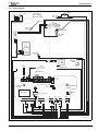
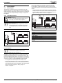
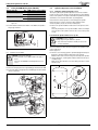
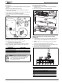
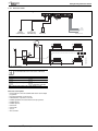
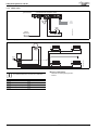
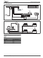
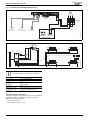
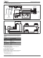
Fitting the integral diverter valve kit 5.7.6 Unvented cylinder with High limit thermal cutout SYSTEM BOILER CONNECTIONS PRE WIRED LINK 230V IN FR FS LR LR 230V OUT EMS N L N L N L N L N L 230V MAINS SUPPLY Junction box A F Outdoor sensor with FW100 only Cylinder NTC Sensor Cylinder Thermostat 6720816348-20.1Wo B B Intelligent controller option Safety Limit Thermostat Dual Thermostat Fig. 28 Wiring diagram (example is showing with Worcester controls) T1 TRV LSV TRV LSV T4 T3 DPFS * T2 JB EMS EMS 3A OR F TRV R LSV TRV LSV 6720816348-21.1Wo RF Fig. 29 System layout (example is showing with Worcester controls) * Radiators in rooms with room thermostats must be uncontrolled and therefore must not have a TRV fitted. F Flow LSV Lock shield valve R Return T1 Cylinder NTC sensor DPFS Double pole fused T2 Worcester time and temperature spur controller JB Junction box T3 Outdoor sensor TRV Thermostatic T4 High limit thermal cut out (separated radiator valve from the dual thermostat) Table 15 Time and temperature control options Although the example here shows the use of Worcester controls with the modified mains supply to the appliance the options listed for the additional equipment are also viable: • Mixed controls ( 5.7.4) • External 230V controls ( 5.7.5) 18 Greenstar i System Compact ErP Optional Integral Diverter Valve - 6 720 816 348 (2015/03)