1
Contents
Contents
1
Key to symbols and safety instructions . . . . . . . . . . . . . . . . . . . 3
1.1
Key to symbols . . . . . . . . . . . . . . . . . . . . . . . . . . . . . . . . . 3
1.2
Safety precautions . . . . . . . . . . . . . . . . . . . . . . . . . . . . . . 3
2
General information . . . . . . . . . . . . . . . . . . . . . . . . . . . . . . . . . . . 4
2.1
Standard package . . . . . . . . . . . . . . . . . . . . . . . . . . . . . . . 4
2.1.1 DHW temperature control . . . . . . . . . . . . . . . . . . . . . . . . . 4
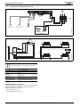
2.1.2 Electrical diagram . . . . . . . . . . . . . . . . . . . . . . . . . . . . . . . 5
3
Pre-installation . . . . . . . . . . . . . . . . . . . . . . . . . . . . . . . . . . . . . . . 6
3.1
General layout . . . . . . . . . . . . . . . . . . . . . . . . . . . . . . . . . . 6
3.1.1 System layout overview . . . . . . . . . . . . . . . . . . . . . . . . . . 6
3.2
Plumbing manifold . . . . . . . . . . . . . . . . . . . . . . . . . . . . . . 7
3.2.1 Connections . . . . . . . . . . . . . . . . . . . . . . . . . . . . . . . . . . . . 7
3.2.2 Diverter valve kit considerations . . . . . . . . . . . . . . . . . . . 8
3.2.3 Appliance Installation and Commissioning . . . . . . . . . . . 8
3.2.4 Fitting the cylinder flow and return service valves . . . . . 8
4
Installation . . . . . . . . . . . . . . . . . . . . . . . . . . . . . . . . . . . . . . . . . . . 8
4.1
Wall mounting template . . . . . . . . . . . . . . . . . . . . . . . . . . 8
4.1.1 Fixing the wall mounting frame . . . . . . . . . . . . . . . . . . . . . 8
4.1.2 Hanging the appliance . . . . . . . . . . . . . . . . . . . . . . . . . . . . 8
5
Fitting the integral diverter valve kit . . . . . . . . . . . . . . . . . . . . . 9
5.1
Assembly of the internal cylinder pipes to the
appliance . . . . . . . . . . . . . . . . . . . . . . . . . . . . . . . . . . . . . . 9
5.1.1 Diverter valve kit plumbing . . . . . . . . . . . . . . . . . . . . . . . . 9
5.2
Fitting the diverter valve motor . . . . . . . . . . . . . . . . . . . . 9
5.3
Access to the HCM (Heating Control Module) . . . . . . . . . 9
5.4
Fitting the HCM (Heating Control Module) . . . . . . . . . 10
5.5
Cylinder temperature sensor installation . . . . . . . . . . 10
5.5.1 Fitting the cylinder temperature sensor . . . . . . . . . . . 10
5.6
Mounting optional plug-in controls . . . . . . . . . . . . . . . . 12
5.6.1 Plug-in programmer/timers . . . . . . . . . . . . . . . . . . . . . 12
5.6.2 EMS controls . . . . . . . . . . . . . . . . . . . . . . . . . . . . . . . . . 12
5.6.3 Remove the blanking plate . . . . . . . . . . . . . . . . . . . . . . 12
5.6.4 Fitting the plug-in controller . . . . . . . . . . . . . . . . . . . . . 13
5.6.5 Secure the plug-in controller . . . . . . . . . . . . . . . . . . . . 13
5.7
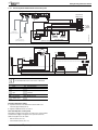
Integral diverter valve kit electrical connection and
system layout. . . . . . . . . . . . . . . . . . . . . . . . . . . . . . . . . . 14
5.7.1 General information . . . . . . . . . . . . . . . . . . . . . . . . . . . 14
5.7.2 Unvented cylinders . . . . . . . . . . . . . . . . . . . . . . . . . . . . 14
5.7.3 Worcester controls . . . . . . . . . . . . . . . . . . . . . . . . . . . . 15
5.7.4 Mixed controls . . . . . . . . . . . . . . . . . . . . . . . . . . . . . . . . 16
5.7.5 External 230V controls . . . . . . . . . . . . . . . . . . . . . . . . . 17
5.7.6 Unvented cylinder with High limit thermal cutout . . . . 18
5.7.7 Unvented cylinder with dual thermostat and
safety valve . . . . . . . . . . . . . . . . . . . . . . . . . . . . . . . . . . . 19
5.8
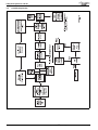
Central heating function . . . . . . . . . . . . . . . . . . . . . . . . 20
5.9
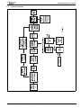
Cylinder heat function . . . . . . . . . . . . . . . . . . . . . . . . . . 21
2
Greenstar i System Compact ErP Optional Integral Diverter Valve - 6 720 816 348 (2015/03)