1
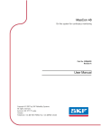
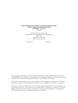
KOMPAKT OTK
Series Air Handling Units Installation
and Maintenance service Manual
EN
Content
Safety Requirements
...................................................................................3
Transportation
...................................................................................3
Brief Description of the Unit
...................................................................................4
Maintenance space requirements
...................................................................................5
Maintenance
...................................................................................6
Technical Information
...................................................................................7
Ordering Key
.................................................................................10
2
Installation and Maintenance Service Manual
Safety Requirements
• To avoid accidents and/or unit damage, only a trained technician must carry
out the connection.
• The appropriate Personal Protective Equipment (PPE) attire is worn relative to
the operation being carried out.
• Electrical equipment is rated, connected and earthed in accordance with CE
regulations.
The air handling unit must be plugged in to an electrical outlet (with earth), which is in good order and
corresponds with all requirements of electric safety.
Before starting any operations inside the unit, make sure that the unit is switched off, and the power cable is
unplugged.
• Earth must be installed according EN61557, BS 7671
• The unit should be installed according to Installation and Maintenance
Manual.
• Before starting the unit, check correct position of air filters.
• Service maintenance should be carried out only in conformity with the instructions specified herein below.
Transportation
The air handling units are ready for transit and storage (1 picture). The unit is packed to prevent damage of the
external and internal parts of the unit, dust and moisture penetration.
Corners of the air handling units are protected against the damage – protective corners are used. The entire unit is wrapped up in protective film. For transit or storage, units are mounted on timber pallets. The unit is
fastened to the pallet with polypropylene packing tape over protective corners.
Unit ready for transit and storage
1 Picture
Forklift truck or hand pallet truck can transport air handling unit as it is shown (2a, b pictures).
We reserve the right to make changes without prior notice.
3
Installation and Maintenance Service Manual
Unit transportation by forklift truck and hand pallet truck
2 b Picture
2 a Picture
2 a Unit is transported by forklift truck on a wooden pallet
2 b Unit is transported by hand pallet truck on a wooden pallet.
The unit should be examined upon receipt, to ensure that no visible damage has occurred during transit, and the
advice note checked to ensure that all items have been received. If damage or delivery shortages are discovered,
the carrier should be immediately informed. AMALVA should be notified within three days of receipt, with a written
confirmation sent within seven days. AMALVA can accept no responsibility for damage by unloading from carrier
or for subsequent damage on site.
If the unit is not to be installed immediately, it should be stored in a clean, dry area. If stored externally, it should
be adequately protected from the weather.
Brief Description of the Unit
• Casings of air handling units are made of galvanized steel sheets, which are powder painted. Mineral wool
is used for thermal insulation and sound attenuation. Unit cover panels are 45 mm thick.
• The air handling units are intended for ventilation of medium-sized spaces (eg. single family houses,
offices, etc.), having operating ambient temperature and relative humidity. As standard, the unit is designed for
indoor placement. The operating temperature range for the unit is -300C ... 400C, outdoor air temperature.
• The air handling unit is not to be used to transport solid particles, even not in areas where there is a risk of
explosive gases.
• KOMFOVENT KOMPAKT OTK is equipped with air filters, an electric or water heater, fans and automation
control system, to ensure safe and efficient operation of the unit.
• Before you open the door, the unit must be switched off and the fans must have been given time to stop (up to
3 minutes).
• The unit contains heating elements that must not be touched when they are hot.
• To maintain a good indoor climate, comply with regulations and, to avoid condensation damage, the unit must
never be stopped apart from during service/maintenance or in connection with an accident.
• If the unit is placed in spaces with high humidity, condensation might occur on the surface of the unit when
outdoor temperatures are very low.
KOMFOVENT KOMPAKT OTK Air Handling Unit Scheme
1
2
3
3 Picture
4
We reserve the right to make changes without prior notice.
1.
2.
3.
Supply air filter;
Supply fan;
Air heater (electric or hot water).
A. Outdoor intake;
B. Supply air.
Installation and Maintenance Service Manual
Maintenance space requirements
It is recommended to install the air handling unit in a separate room or in the attic on a hard smooth surface
insulated with a rubber mat. The place for the unit should be selected with allowance for minimum access to the
unit for maintenance and service inspection. The minimum free space in front of the control panel should be not
less than 700 mm (picture 4a).
The equipment can be mounted in the suspended ceiling or on the wall, see the mounting scheme
(picture 4b, c).
min. 700 mm
2
B
Maintenance space for unit
1
2
3
A
B
5
4 a Picture
4
5
A
min. 1800 mm
min. 100 mm
A
B
ceiling
5
4 b Picture
1. Air handling unit
2. Air duct connections
3. Sound attenuator
4. Rubber mat (not included in unit set)
5. Bracket (4b, c pictures)
We reserve the right to make changes without prior notice.
min. 700 mm
4 c Picture
5
Installation and Maintenance Service Manual
Ductwork
The air flows in/out air handling unit through ductwork. We recommend using galvanized steel (Zn 275 gr/m2)
ductwork, to ensure easy cleaning and durability. It is necessary to use the ductwork system with low air flow rate
and small pressure drop to have necessary air volume and low sound level and save the energy. The appropriate
sound attenuators will reduce the noise level of the fans in the premises.
All ductwork should be insulated with 50–100 mm thickness insulation to avoid the condensation.
Note: temperature sensor B1 has to be mounted in the supply air duct under electric heater (see the functional
diagram in Control System Installation and Operation Manual). It is necessary to leave space in straight air
duct for sensor mounting and guarantee the space for maintenance and service work. Minimal space between the unit and B1 sensor is the space of double air duct diameter.
Ductwork, steelwork and any other services should not be supported off the unit
In duct system, for units with electric air heater, use air closing damper without
spring return mechanism.
In case of power failure is necessary to ensure the operation of the fan for 2
minutes.
Final Inspection
After installation of the unit, a thorough inspection should be carried out. This should include inspecting the
inside of the unit and removing debris and tools, which may have been left behind by on site contractors. Replace
any panels, which may have been removed and close all access doors, ensuring that the door sealing gaskets
have not been damaged.
Maintenance
It is recommended to carry out routine maintenance of the air handling unit KOMFOVENT KOMPAKT OTK 3 – 4 times per year. Besides preventive maintenance inspection, the following operations should be
performed:
Before performing any inspection work, check whether the unit is switched
off from the electric power supply.
1. Fans check (once per year). Polluted fans decrease efficiency.
Fans should be carefully cleaned with textile or soft brush. Do not use water. Do not break balance. Check
if fan freely rotates and is not mechanically damaged, if impeller does not touch suction nozzles, fan does
not spread noise, the pressure tubes are connected to the nozzle (if it is required), mounting bolts are
screwed.
2. Air heater check. Recommended to perform periodical inspection and cleaning of heater. Check the plates
of water air heater. The air heater is cleaned with hoover from supply air side or with air blast from exhaust
air side. If it is very dirty, wash with tepid water, which will not make corrosion of aluminium. Check if position
of return water temperature sensor is right.
6
Check if electric air heater is properly fixed, wires connections are not damaged and heating elements are
not bent. They can be damaged or bent due to uneven heat or uneven and turbulent air direction. Check if
electric air heater is clear of unnecessary things and heating elements are not clogged, because this can
cause unpleasant smell or in the worst case – dust can start burning. Air flow through the air heater should
be greater than 1,5 m/s. Heating elements can be cleaned with hoover or wet textile.
We reserve the right to make changes without prior notice.
Installation and Maintenance Service Manual
3. Air damper check (if it is required). Not fully opened outside air damper rises up the pressure in the system. Water air heater can freeze if outside air damper does not fully close in not working air handling unit.
Mounting and running of air damper should be checked and regulated.
4. Air filter clogging check. Change air filters when air filter clogging is indicated. We recommend to change
filters at least twice per year: before and after heating season, or more*.
If air handling unit is working in small speed, the filters must be checked on unit maximum speed. Filters are
one time used. We do not recommend cleaning them. Stop the air handling unit before changing filters.
* Clogged filters unbalance ventilation system, air handling unit uses more power.
Technical Information
Type
Weight
Supply
voltage
Operating
current
Heater
capacity
Fans input
power
Ducts
connection
Filter
class
Filter
type
Filters’
dimensions
OTK
kg
V
A
kW
W
mm
700PE
32,5
1x230
13,8
3
165
200
F5
Panel
345x287x46
bxhxl, mm
700PE
32,5
3x400
9,4
6
165
200
F5
Panel
345x287x46
700PE
32,5
3x400
13,8
9
165
200
F5
Panel
345x287x46
1200PE
45,5
3x400
14,3
9
290
250
F5
Panel
558x287x46
1200PE
45,5
3x400
23,0
15
290
250
F5
Panel
558x287x46
2000PE
72,5
3x400
35,1
22,5
2x290
700x250
F5
Panel
858x287x46
2000PE
72,5
3x400
46,0
30
2x290
700x250
F5
Panel
858x287x46
2000PE
72,5
3x400
24,2
15
2x290
700x250
F5
Panel
858x287x46
1200PW
45,5
1x230
1,8
15
290
250
F5
Panel
558x287x46
2000PW
72,5
1x230
3
30
2x290
700x250
F5
Panel
858x287x46
3000PW
120
3x400
2,2
45
990
600x400
F7
Panel
450x480x96(x2)
4000PW
120
3x400
2,3
45
990
600x400
F7
Panel
450x480x96(x2)
OTK Acoustic data
OTK 700
Lw, dB
63
125
250
500
1000
2000
4000
8000
LpA, dB(A)
Supply air flow
(into air ducts)
Intake
59
65
66
65
61
53
47
41
65,9
Supply
60
67
69
69
64
56
51
47
69,0
54
58
56
47
43
35
28
23
51,0
Surrounding (3 m distance)
OTK 1200
Lw, dB
63
125
250
500
1000
2000
4000
8000
LpA, dB(A)
Supply air flow
(into air ducts)
Intake
64
71
72
72
66
58
52
45
71,8
Supply
67
74
76
76
71
62
57
52
76,0
59
63
62
52
47
39
30
25
56,2
Surrounding (3 m distance)
OTK 2000
Lw, dB
63
125
250
500
1000
2000
4000
8000
LpA, dB(A)
Supply air flow
(into air ducts)
Intake
67
74
75
69
60
54
47
74,7
56,2
Supply
69
77
79
79
73
64
59
54
78,9
61
66
65
54
49
40
32
26
58,5
Surrounding (3 m distance)
We reserve the right to make changes without prior notice.
7
Installation and Maintenance Service Manual
Schemes
OTK 700PE
OTK 1200PE/W
OTK 2000PE/W
OTK 3000PW - 4000PW
Static pressure, Pa
OTK Performance
OTK 2000P/E
OTK 700P/E
OTK 1200P/E
OTK 1200P/W
Supply air flow, m3/h
8
We reserve the right to make changes without prior notice.
OTK 2000P/W
Installation and Maintenance Service Manual
OTK-3000PW-EC-C3
Static pressure, Pa
Supply air flow, m3/s
Supply air flow, m3/h
OTK 3000
Lw, dB
63
125
250
500
1000
2000
4000
8000
LpA, dB(A)
Supply air flow
(into air ducts)
Intake
-9
-4
-4
-5
-9
-16
-21
-26
-4,1
Supply
-8
-2
-1
-1
-5
-12
-16
-20
0,0
-26
-22
-23
-30
-34
-41
-47
-51
-27,4
Surrounding (3 m distance)
OTK-4000PW-EC-C3
Static pressure, Pa
Supply air flow, m3/s
SFP is shown for one fan.
We reserve the right to make changes without prior notice.
Supply air flow, m3/h
9
Installation and Maintenance Service Manual
OTK 4000
Lw, dB
63
125
250
500
1000
2000
4000
8000
LpA, dB(A)
Supply air flow
(into air ducts)
Intake
-9
-4
-4
-5
-9
-16
-21
-26
-4,1
Supply
-8
-2
-1
-1
-5
-12
-16
-20
0,0
-26
-22
-23
-30
-34
-41
-47
-51
-27,4
Surrounding (3 m distance)
Ordering Key
OTK 700
OTK 1200
P
P
E/W – CX
E/W – CX
OTK 2000
P
E/W – CX
OTK 3000
P
W
– CX
OTK 4000
P
W
– CX
Controller type
Electric / Water air heater
Version - flat
Unit size (shows nominal air flow)
AHU type: OTK - air supply unit
Ordering sample:
OTK 3000
P
W
– C3
Controller type
Water air heater
Version - flat
Unit size (shows nominal air flow)
AHU type: OTK - air supply unit
10
We reserve the right to make changes without prior notice.
UAB AMALVA
Ozo str. 10,
LT–08200 Vilnius, LITHUANIA
e-mail [email protected]
www.amalva.com
www.komfovent.com
2012