1
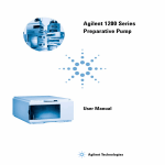
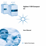
Agilent 1200 Series
Isocratic Pump
User Manual
1200 Series Isocratic Pump User Manual
Agilent Technologies
Notices
© Agilent Technologies, Inc. 2006-2007,
2008
No part of this manual may be reproduced
in any form or by any means (including electronic storage and retrieval or translation
into a foreign language) without prior agreement and written consent from Agilent
Technologies, Inc. as governed by United
States and international copyright laws.
Manual Part Number
G1310-90011
Edition
11/08
Printed in Germany
Agilent Technologies
Hewlett-Packard-Strasse 8
76337 Waldbronn
Research Use Only
Not for use in Diagnostic Procedures.
Warranty
The material contained in this document is provided “as is,” and is subject to being changed, without notice,
in future editions. Further, to the maximum extent permitted by applicable
law, Agilent disclaims all warranties,
either express or implied, with regard
to this manual and any information
contained herein, including but not
limited to the implied warranties of
merchantability and fitness for a particular purpose. Agilent shall not be
liable for errors or for incidental or
consequential damages in connection
with the furnishing, use, or performance of this document or of any
information contained herein. Should
Agilent and the user have a separate
written agreement with warranty
terms covering the material in this
document that conflict with these
terms, the warranty terms in the separate agreement shall control.
receive no greater than Restricted Rights as
defined in FAR 52.227-19(c)(1-2) (June
1987). U.S. Government users will receive
no greater than Limited Rights as defined in
FAR 52.227-14 (June 1987) or DFAR
252.227-7015 (b)(2) (November 1995), as
applicable in any technical data.
Safety Notices
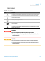
CAUTION
A CAUTION notice denotes a
hazard. It calls attention to an
operating procedure, practice, or
the like that, if not correctly performed or adhered to, could
result in damage to the product
or loss of important data. Do not
proceed beyond a CAUTION
notice until the indicated conditions are fully understood and
met.
Technology Licenses
The hardware and/or software described in
this document are furnished under a license
and may be used or copied only in accordance with the terms of such license.
Restricted Rights Legend
If software is for use in the performance of a
U.S. Government prime contract or subcontract, Software is delivered and licensed as
“Commercial computer software” as
defined in DFAR 252.227-7014 (June 1995),
or as a “commercial item” as defined in FAR
2.101(a) or as “Restricted computer software” as defined in FAR 52.227-19 (June
1987) or any equivalent agency regulation
or contract clause. Use, duplication or disclosure of Software is subject to Agilent
Technologies’ standard commercial license
terms, and non-DOD Departments and
Agencies of the U.S. Government will
WA R N I N G
A WARNING notice denotes a
hazard. It calls attention to an
operating procedure, practice,
or the like that, if not correctly
performed or adhered to, could
result in personal injury or
death. Do not proceed beyond a
WARNING notice until the indicated conditions are fully understood and met.
1200 Series Isocratic Pump User Manual
Contents
Contents
1 Introduction
5
Introduction to the Isocratic Pump 6
Overview of the Hydraulic Path 7
Instrument Layout 13
Electrical Connections 14
Agilent 1200 Series Interfaces 16
2 Site Requirements and Specifications
17
Site Requirements 18
Physical Specifications 21
Performance Specifications 22
3 Installing the Pump
25
Unpacking the Isocratic Pump 26
Optimizing the Stack Configuration 28
Installing the Isocratic Pump 31
Connecting Modules and Control Software 34
Flow Connections of the Isocratic Pump 37
Priming and Purging the System 40
4 Using the Isocratic Pump
45
Hints for Successful Use of the Pump 46
Solvent Information 47
Prevent Blocking of Solvent Filters 48
Algae Growth in HPLC Systems 49
5 Optimiziming Performance
51
When to Use a Vacuum Degasser 52
When to use the Seal Wash Option 53
When to Use Alternative Seals 54
Optimize the Compressibility Compensation Setting
1200 Series Isocratic Pump User Manual
55
3
Contents
6 Troubleshooting and Diagnostics
57
Agilent Lab Advisor Software 58
Overview of the Pump’s Indicators and Test Functions
Status Indicators 60
User Interfaces 62
7 Maintenance
59
63
Introduction to Maintenance and Repair 64
Early Maintenance Feedback (EMF) 67
Overview of Maintenance and Repair 69
Simple Repairs 71
8 Parts and Materials for Maintenance
99
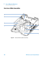
Overview of Main Assemblies 100
Pump Head Assembly 104
Pump Head Assembly with Seal Wash Option
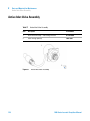
Outlet Ball Valve Assembly 108
Purge Valve Assembly 109
Active Inlet Valve Assembly 110
Accessory Kit G1311-68705 111
Seal Wash Option Kit G1311-68711 112
9 Appendix
106
113
General Safety Information 114
The Waste Electrical and Electronic Equipment (WEEE) Directive
(2002/96/EC) 118
Lithium Batteries Information 119
Radio Interference 120
Sound Emission 121
Solvent Information 122
Agilent Technologies on Internet 124
4
1200 Series Isocratic Pump User Manual
1200 Series Isocratic Pump User Manual
1
Introduction
Introduction to the Isocratic Pump
6
Overview of the Hydraulic Path 7
How Does the Pump Work? 8
How Does Compressibility Compensation Work?
How Does Variable Stroke Volume Work? 12
Early Maintenance Feedback (EMF) 12
Instrument Layout
11
13
Electrical Connections
14
Agilent 1200 Series Interfaces
16
Agilent Technologies
5
1
Introduction
Introduction to the Isocratic Pump
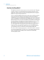
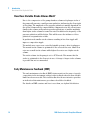
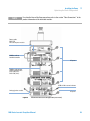
Introduction to the Isocratic Pump
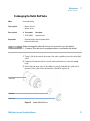
The isocratic pump comprises a pump assembly and a damping unit.
Degassing is not included but avacuum degasser is available as a separate
product for applications that require best flow stability especially at low flow
rates or highest detector sensitivity. This is most likely required to run small
internal diameter columns (2 mm and 1 mm i.d.) which require low flow rates.
A solvent cabinet provides enough space for up to four one liter bottles. An
active seal wash (optional) is available when the pump is used with
concentrated buffer solutions.
EdlZghjeean
AEBWdVgY
;Vc
EjbeYg^kZ
Ejbe]ZVY
DjiaZiWVaakVakZ
Ejg\ZkVakZ
6Xi^kZ^caZikVakZ
9VbeZg
Figure 1
6
Overview of the Isocratic Pump
1200 Series Isocratic Pump User Manual
Introduction
Overview of the Hydraulic Path
1
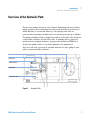
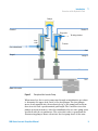
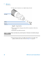
Overview of the Hydraulic Path
The isocratic pump is based on a two-channel, dual-plunger in-series design
which comprises all essential functions that a solvent delivery system has to
fulfill. Metering of solvent and delivery to the high-pressure side are
performed by one pump assembly which can generate pressure up to 400 bar.
The pump assembly includes a pump head with an active inlet valve which has
a replaceable cartridge, and an outlet valve. A damping unit is connected
between the two plunger chambers. A purge valve including a PTFE frit is
fitted at the pump outlet for convenient priming of the pump head.
An active seal wash (optional) is available when the isocratic pump is used
with concentrated buffer solutions.
9VbeZg
Ejg\ZkVakZ
DjiaZiWVaakVakZ
Ejbe]ZVY
6Xi^kZ^caZikVakZ
Figure 2
Hydraulic Path
1200 Series Isocratic Pump User Manual
7
1
Introduction
Overview of the Hydraulic Path
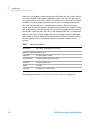
How Does the Pump Work?
The liquid runs from the solvent reservoir to the active inlet valve. The pump
assembly comprises two substantially identical plunger pump units. Both
pump units comprise a ball-screw drive and a pump head with one sapphire
plunger for reciprocating movement in it.
A servo-controlled variable reluctance motor drives the two ball screw drives
in opposite directions. The gears for the ball-screw drives have different
circumferences (ratio 2:1) allowing the first plunger to move at twice the speed
of the second plunger. The solvent enters the pump heads close to the bottom
limit and leaves it at its top. The outer diameter of the plunger is smaller than
the inner diameter of the pump head chamber allowing the solvent to fill the
gap in between. The first plunger has a stroke volume in the range of
20 – 100 µl depending on the flow rate. The microprocessor controls all flow
rates in a range of 1 µl – 10 ml/min. The inlet of the first pumping unit is
connected to the active inlet valve which is processor-controlled opened or
closed allowing solvent to be drawn into the first plunger pump unit.
The outlet of the first plunger pump unit is connected through the outlet ball
valve and the damping unit to the inlet of the second plunger pump unit. The
outlet of the purge valve assembly is then connected to the following
chromatographic system.
8
1200 Series Isocratic Pump User Manual
Introduction
Overview of the Hydraulic Path
1
9VbeZg
8]VbWZg&
8]VbWZg'
Ejg\ZkVakZ
Idb^m^c\X]VbWZg
>caZi
kVakZ
DjiaZi
kVakZ
IdlVhiZ
;gdbhdakZciWdiiaZ
HZVa
Eajc\Zg&
Eajc\Zg'
7VaahXgZlYg^kZ
<ZVg
Bdidgl^i]ZcXdYZg
Figure 3
Principle of the Isocratic Pump
When turned on, the isocratic pump runs through an initialization procedure
to determine the upper dead center of the first plunger. The first plunger
moves slowly upwards into the mechanical stop of the pump head and from
there it moves back a predetermined path length. The controller stores this
plunger position in memory. After this initialization the isocratic pump starts
operation with the set parameters. The active inlet valve is opened and the
down-moving plunger draws solvent into the first pump head. At the same
1200 Series Isocratic Pump User Manual
9
1
Introduction
Overview of the Hydraulic Path
time the second plunger is moving upwards delivering into the system. After a
controller-defined stroke length (depending on the flow rate) the drive motor
is stopped and the active inlet valve is closed. The motor direction is reversed
and moves the first plunger up until it reaches the stored upper limit and at
the same time moving the second plunger downwards. Then the sequence
starts again moving the plungers up and down between the two limits. During
the up movement of the first plunger the solvent in the pump head is pressed
through the outlet ball valve into the second pumping unit. The second plunger
draws in half of the volume displaced by the first plunger and the remaining
half volume is directly delivered into the system. During the drawing stroke of
the first plunger, the second plunger delivers the drawn volume into the
system.
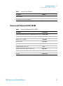
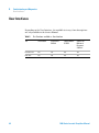
Table 1
Isocratic Pump Details
Dead volume
800–1100 µl, dependent on back pressure
Materials in contact with mobile phase
Pump head
SST, gold, sapphire, ceramic
Active inlet valve
SST, gold, sapphire, ruby, ceramic, PTFE
Outlet valve
SST, gold, sapphire, ruby
Adapter
SST, gold
Purge valve
SST, gold, PTFE, ceramic, PEEK
For pump specifications, see “Performance Specifications” on page 22.
10
1200 Series Isocratic Pump User Manual
Introduction
Overview of the Hydraulic Path
1
How Does Compressibility Compensation Work?
The compressibility of the solvents in use will affect retention-time stability
when the back pressure in the system changes (for example, ageing of
column). In order to minimize this effect, the pump provides a compressibility
compensation feature which optimizes the flow stability according to the
solvent type. The compressibility compensation is set to a default value and
can be changed through the user interface.
Without a compressibility compensation the following will happen during a
stroke of the first plunger. The pressure in the plunger chamber increases and
the volume in the chamber will be compressed depending on backpressure and
solvent type. The volume displaced into the system will be reduced by the
compressed volume.
With a compressibility value set the processor calculates a compensation
volume, that is depending on the backpressure in the system and the selected
compressibility. This compensation volume will be added to the normal stroke
volume and compensates the previous described loss of volume during the
delivery stroke of the first plunger.
1200 Series Isocratic Pump User Manual
11
1
Introduction
Overview of the Hydraulic Path
How Does Variable Stroke Volume Work?
Due to the compression of the pump-chamber volume each plunger stroke of
the pump will generate a small pressure pulsation, influencing the flow ripple
of the pump. The amplitude of the pressure pulsation is mainly dependent on
the stroke volume and the compressibility compensation for the solvent in use.
Small stroke volumes will generate pressure pulsations of smaller amplitude
than higher stroke volumes at same flow rates. In addition the frequency of the
pressure pulsations will be higher. This will decrease the influence of flow
pulsations on quantitative results.
In gradient mode smaller stroke volumes resulting in less flow ripple will
improve composition ripple.
The module uses a processor-controlled spindle system to drive its plungers.
The normal stroke volume is optimized for the selected flow rate. Small flow
rates use a small stroke volume while higher flow rates use a higher stroke
volume.
The stroke volume for the pump is set to AUTO mode. This means that the
stroke is optimized for the flow rate in use. A change to larger stroke volumes
is possible but not recommended.
Early Maintenance Feedback (EMF)
The early maintenance feedback (EMF) feature monitors the usage of specific
components in the instrument, and provides feedback when the user-settable
limits have been exceeded. The visual feedback in the user interface provides
an indication that maintenance procedures should be scheduled.
For details on EMF counters and how to use them, see Agilent Lab Advisor.
12
1200 Series Isocratic Pump User Manual
Introduction
Instrument Layout
1
Instrument Layout
The industrial design of the module incorporates several innovative features.
It uses Agilent’s E-PAC concept for the packaging of electronics and
mechanical assemblies. This concept is based upon the use of expanded
polypropylene (EPP) layers foam plastic spacers in which the mechanical and
electronic boards components of the module are placed. This pack is then
housed in a metal inner cabinet which is enclosed by a plastic external
cabinet. The advantages of this packaging technology are:
• virtual elimination of fixing screws, bolts or ties, reducing the number of
components and increasing the speed of assembly/disassembly,
• the plastic layers have air channels molded into them so that cooling air can
be guided exactly to the required locations,
• the plastic layers help cushion the electronic and mechanical parts from
physical shock, and
• the metal inner cabinet shields the internal electronics from
electromagnetic interference and also helps to reduce or eliminate radio
frequency emissions from the instrument itself.
1200 Series Isocratic Pump User Manual
13
1
Introduction
Electrical Connections
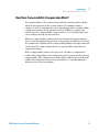
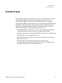
Electrical Connections
• The GPIB connector is used to connect the pump with a computer. The
address and control switch module next to the GPIB connector determines
the GPIB address of your pump. The switches are preset to a default
address. This address is recognized at powercycling the module.
• The CAN bus is a serial bus with high speed data transfer. The two
connectors for the CAN bus are used for internal Agilent 1200 Series
module data transfer and synchronization.
• One analog output provides a pressure signal for integrators or data
handling systems.
• The interface board slot is used for external contacts and BCD bottle
number output or LAN connections.
• The REMOTE connector may be used in combination with other analytical
instruments from Agilent Technologies if you want to use features such as
start, stop, common shut down, prepare, and so on.
• With the appropriate software, the RS-232C connector may be used to
control the module from a computer through a RS-232C connection. This
connector is activated and can be configured with the configuration switch
next to the GPIB connector. See your software documentation for further
information.
• The power input socket accepts a line voltage of 100–120 or 220–240 volts
AC ± 10% with a line frequency of 50 or 60 Hz. Maximum power
consumption is 220 VA. There is no voltage selector on your module because
the power supply has wide-ranging capability. There are no externally
accessible fuses, because automatic electronic fuses are implemented in the
power supply. The security lever at the power input socket prevents the
module cover from being taken off when line power is still connected.
14
1200 Series Isocratic Pump User Manual
Introduction
Electrical Connections
1
HZXjg^inaZkZg
Hadi[dg^ciZg[VXZWdVgY
6cVad\egZhhjgZ!
'bK$WVg
6E<GZbdiZ
GH"'('8
86C
<E>7
EdlZg
8dc[^\jgVi^dchl^iX]
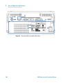
Figure 4
Rear View of Pump - Electrical Connections and Label
1200 Series Isocratic Pump User Manual
15
1
Introduction
Agilent 1200 Series Interfaces
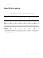
Agilent 1200 Series Interfaces
The Agilent 1200 Series modules provide the following interfaces:
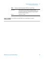
Table 2
Agilent 1200 Series Interfaces
Interface Type
Pumps
Autosampler
DA Detector
MW Detector
FL Detector
VW Detector
RI Detector
Thermostatted Vacuum
Column
Degasser
Compartment
CAN
Yes
Yes
Yes
Yes
Yes
No
GPIB
Yes
Yes
Yes
Yes
Yes
No
RS-232C
Yes
Yes
Yes
Yes
Yes
No
APG Remote
Yes
Yes
Yes
Yes
Yes
Yes
Analog
Yes
No
2×
1×
No
Yes1
Interface board2
Yes
Yes
Yes
Yes
No
No
1
The vacuum degasser will have a special connector for specific use. For details, see the degasser manual.
2
The interface board slot (not common to all modules) provides specific interfacing needs (external contacts, BCD, LAN and so on).
16
1200 Series Isocratic Pump User Manual
1200 Series Isocratic Pump User Manual
2
Site Requirements and Specifications
Site Requirements 18
Power Consideration
Power Cords 19
Bench Space 20
Environment 20
Physical Specifications
18
21
Performance Specifications
22
Agilent Technologies
17
2
Site Requirements and Specifications
Site Requirements
Site Requirements
A suitable environment is important to ensure optimum performance of the
instrument.
Power Consideration
The module power supply has wideranging capability (see Table 3 on page 21).
It accepts any line voltage in the range described in the above mentioned table.
Consequently there is no voltage selector in the rear of the module. There are
also no externally accessible fuses, because automatic electronic fuses are
implemented in the power supply.
WA R N I N G
Incorrect line voltage at the instrument
Shock hazard or damage of your instrumentation can result, if the devices are
connected to a line voltage higher than specified.
➔ Connect your instrument to the specified line voltage.
WA R N I N G
Module is partially energized when switched off, as long as the power cord is
plugged in.
Repair work at the module can lead to personal injuries, e.g. shock hazard, when the
cover is opened and the module is connected to power.
➔ Remove the power cable from the instrument before opening the cover.
➔ Do not connect the power cable to the Instrument while the covers are removed.
18
1200 Series Isocratic Pump User Manual
2
Site Requirements and Specifications
Site Requirements
CAUTION
Unaccessable power plug.
In case of emergency it must be possible to disconnect the instrument from the power
line at any time.
➔ Make sure the power connector of the instrument can be easily reached and
unplugged.
➔ Provide sufficient space behind the power socket of the instrument to unplug the
cable.
Power Cords
Different power cords are offered as options with the module. The female end
of all power cords is identical. It plugs into the power-input socket at the rear
of the module. The male end of each power cord is different and designed to
match the wall socket of a particular country or region.
WA R N I N G
The absence of ground connection and the use of an unspecified power cord can
lead to electric shock or short circuit.
Electric Shock
➔ Never operate your instrumentation from a power outlet that has no ground
connection.
➔ Never use a power cord other than the Agilent Technologies power cord designed
for your region.
WA R N I N G
Use of unsupplied cables
Using cables not supplied by Agilent Technologies can lead to damage of the
electronic components or personal injury.
➔ Never use cables other than the ones supplied by Agilent Technologies to ensure
proper functionality and compliance with safety or EMC regulations.
1200 Series Isocratic Pump User Manual
19
2
Site Requirements and Specifications
Site Requirements
Bench Space
The module dimensions and weight (see Table 3 on page 21) allow to place the
module on almost any laboratory bench. It needs an additional 2.5 cm
(1.0 inches) of space on either side and approximately 8 cm (3.1 inches) in the
rear for the circulation of air and electric connections.
If the bench should carry a complete Agilent 1200 Series system, make sure
that the bench is designed to carry the weight of all the modules.
NOTE
The module should be operated in a horizontal position!
Environment
Your module will work within specifications at ambient temperatures and
relative humidity as described in Table 3 on page 21.
CAUTION
Condensation within the module
Condensation will damage the system electronics.
➔ Do not store, ship or use your module under conditions where temperature
fluctuations could cause condensation within the module.
➔ If your module was shipped in cold weather, leave it in its box and allow it to warm
slowly to room temperature to avoid condensation.
20
1200 Series Isocratic Pump User Manual
2
Site Requirements and Specifications
Physical Specifications
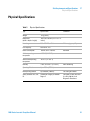
Physical Specifications
Table 3
Physical Specifications
Type
Specification
Weight
11 kg (25 lbs)
Dimensions
(width × depth × height)
140 x 345 x 435 mm (5.5 x 13.5 x 17
inches)
Line voltage
100 – 240 VAC, ± 10%
Line frequency
50 or 60 Hz, ± 5%
Power consumption
180 VA, 55 W / 188 BTU
Ambient operating
temperature
4–55 °C (41–131 °F)
Ambient non-operating
temperature
-40–70 °C (-4–158 °F)
Humidity
< 95%, at 25–40 °C (77–104 °F)
Operating Altitude
Up to 2000 m (6500 ft)
Non-operating altitude
Up to 4600 m (14950 ft)
For storing the module
Safety standards: IEC, CSA,
UL
Installation Category II, Pollution
Degree 2
For indoor use only. Research
Use Only. Not for use in
Diagnostic Procedures.
1200 Series Isocratic Pump User Manual
Comments
Wide-ranging capability
Maximum
Non-condensing
21
2
Site Requirements and Specifications
Performance Specifications
Performance Specifications
Table 4
Performance Specification Agilent 1200 Series Isocratic Pump
Type
Specification
Hydraulic system
Dual piston in series pump with proprietary servo-controlled variable
stroke drive, floating pistons and active inlet valve
Setable flow range
0.001 – 10 ml/min, in 0.001 ml/min increments
Flow range
0.2 – 10.0 ml/min
Flow precision
<= 0.07 % RSD, or <= 0.02 min SD whatever is greater, based on
retention time at constant room temperature
Flow accuracy
±1 % or 10µl/min whatever is greater
Pressure
Operating range 0 – 40 MPa (0 – 400 bar, 0 – 5880 psi) up to 5 ml/min
Operating range 0 – 20 MPa (0 – 200 bar, 0 – 2950 psi) up to 10 ml/min
Pressure pulsation
< 2 % amplitude (typically < 1 %), at 1 ml/min isopropanol, at all
pressures > 10 bar (147 psi)
Compressibility
compensation
User-selectable, based on mobile phase compressibility
Recommended pH
range
1.0 – 12.5, solvents with pH < 2.3 should not contain acids which attack
stainless steel
Control and data
evaluation
Agilent Control Software (Chemstation, EZ-Chrom, OL, etc.)
Analog output
For pressure monitoring, 2 mV/bar, one output
Communications
Controller-area network (CAN), GPIB, RS-232C, APG Remote: ready,
start, stop and shut-down signals, LAN optional
Safety and maintenance Extensive diagnostics, error detection and display (through control
module and Agilent Lab Monitor &Diagnostic Software), leak detection,
safe leak handling, leak output signal for shutdown of pumping system.
Low voltages in major maintenance areas.
22
1200 Series Isocratic Pump User Manual
Site Requirements and Specifications
Performance Specifications
Table 4
NOTE
2
Performance Specification Agilent 1200 Series Isocratic Pump
GLP features
Early maintenance feedback (EMF) for continuous tracking of
instrument usage in terms of seal wear and volume of pumped mobile
phase with user-settable limits and feedback messages. Electronic
records of maintenance and errors.
Housing
All materials recyclable.
For use with flow rates below 500 µl/min a vacuum degasser is required.
1200 Series Isocratic Pump User Manual
23
2
24
Site Requirements and Specifications
Performance Specifications
1200 Series Isocratic Pump User Manual
1200 Series Isocratic Pump User Manual
3
Installing the Pump
Unpacking the Isocratic Pump 26
Damaged Packaging 26
Delivery Checklist 26
Accessory Kit Contents G1311-68705
Optimizing the Stack Configuration
Installing the Isocratic Pump
27
28
31
Connecting Modules and Control Software 34
Connecting Agilent 1200 Series modules 34
Connecting an Agilent 1200 Series Vacuum Degasser 35
Connecting control software and/or control modules 35
Flow Connections of the Isocratic Pump
Priming and Purging the System
Priming with a Syringe 41
Priming with the Pump 43
37
40
Agilent Technologies
25
3
Installing the Pump
Unpacking the Isocratic Pump
Unpacking the Isocratic Pump
Damaged Packaging
Upon receipt of your module, inspect the shipping containers for any signs of
damage. If the containers or cushioning material are damaged, save them until
the contents have been checked for completeness and the instrument has been
mechanically and electrically checked. If the shipping container or cushioning
material is damaged, notify the carrier and save the shipping material for the
carrier’s inspection.
Delivery Checklist
Ensure all parts and materials have been delivered with the isocratic pump.
The delivery checklist is shown in Table 5 on page 26. To aid in parts
identification, please see “Overview of Main Assemblies” on page 100. Please
reportmissing or damaged parts to your local Agilent Technologies sales and
service office.
Table 5
26
Isocratic Pump Checklist
Description
Quantity
Isocratic pump
1
Solvent cabinet
1 (5065-9981)
Amber solvent bottle
1 (9301-1450)
Bottle-head assembly
1 (G1311-60003)
Waste tube, purge valve
1 (5042-2461, reorder number, 5
m)
Power cable
1
CAN cable, 1 m
1
Remote cable
As ordered
Signal cable
As ordered
1200 Series Isocratic Pump User Manual
Installing the Pump
Unpacking the Isocratic Pump
Table 5
3
Isocratic Pump Checklist
Description
Quantity
Service Manual
1
Accessory kit (see Table 6 on page 27)
1
Accessory Kit Contents G1311-68705
Table 6
Accessory Kit Contents G1311-68705
Description
Part Number
Capillary, pump to injection device, length 900 mm, ID 0.17 mm G1329-87300
Seal insert tool
01018-23702
Wrench; 1/4 – 5/16 inch
8710-0510
Wrench; 14 mm
8710-1924
Hex key 4 mm
8710-2392
Corrugated Waste Tube (1.2 m)
no PN
Corrugated Waste tube (reorder number, 5 m)
5062-2463
Velocity regulator (reorder number, pack of 3)
5062-2486
PTFE Frit
01018-22707
1200 Series Isocratic Pump User Manual
27
3
Installing the Pump
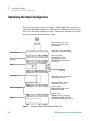
Optimizing the Stack Configuration
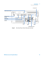
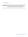
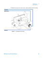
Optimizing the Stack Configuration
If your isocratic pump is part of a complete Agilent 1200 Series system, you
can ensure optimum performance by limiting the configuration of the system
stack to the following configuration. This configuration optimizes the system
flow path, ensuring minimum delay volume.
;adlXdccZXi^dch^ci]ZhiVX`/
:mVbeaZhZijel^i]%#&,bb>9
\gZZcXVe^aaVg^Zh
HdakZciWdiiaZ"ejbe/<&(&&"+%%%(
WdiiaZ"]ZVYVhhZbWan!EI;:"ijW^c\h
HdakZci8VW^cZi
Ejbe"VjidhVbeaZg/
<&(&'"+,(%*HHI!\gZZc
Ejbeejg\ZkVakZ"lVhiZ/
*%+'"')+&EI;:ijW^c\l^YZWdgZ!
gZdgYZgeVX`
9Z\VhhZg
Ejbe
>chiVciE^adi
6jidhVbeaZg
6jidhVbeaZg"XdajbcXdbeVgibZci/
<&(&("-,(%*HHI!\gZZc
8dajbcXdbeVgibZci"Xdajbc/
<&(&+"-,(%%HHI!\gZZc
8dajbc"YZiZXidg/
969<&(&*"-,(&&HHI!XdViZY
KL9*%+'"-*''E::@
8dajbc8dbeVgibZci
9ZiZXidg"lVhiZ/
969%-.%"&,&(EI;:!l^YZWdgZ
KL9*%+'"-*(*E::@!*%+'"')+(
Xdggj\ViZYlVhiZijW^c\!gZdgYZgeVX`
9ZiZXidg
Figure 5
28
Recommended Stack Configuration (Front View).
1200 Series Isocratic Pump User Manual
Installing the Pump
Optimizing the Stack Configuration
NOTE
3
For a detailed view of the flow connections refer to the section “Flow Connections” in the
product information of the individual modules.
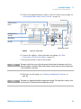
GZbdiZXVWaZ
*%+&"((,EgZhhjgZdjiejiidgZXdgYZg
86C7jhXVWaZid
]VcY]ZaYXdcigdaaZg
68edlZg
86C7jhXVWaZ[dg^ciZg
bdYjaZXdbbjc^XVi^dc
*&-&"&*&+%#*b
*&+&"&*&.&#%b
<E>7dgA6CidXdcigdahd[ilVgZ
6cVad\h^\cVaidgZXdgYZg
Figure 6
68edlZg
Recommended Stack Configuration (Rear View)
1200 Series Isocratic Pump User Manual
29
3
Installing the Pump
Optimizing the Stack Configuration
NOTE
30
If a single stack configuration becomes too high, e.g. if an additional module like a G1327A
ALS Thermostat is added or if your bench is too high, a two stack configuration may be a
better setup. Separate the stack between pump and autosampler and place the stack
containing the pump on the right side of the stack containing the autosampler.
1200 Series Isocratic Pump User Manual
Installing the Pump
Installing the Isocratic Pump
3
Installing the Isocratic Pump
Parts required
#
Part number
1
1
Preparations
WA R N I N G
Description
Pump
Power cord, for other cables see text below
1
G4208A
Control Software (ChemStation, EZChrom, OL, etc.)
1
G1323B
and/or a handheld controller (Instant Pilot or Control Module)
•
•
•
Locate bench space.
Provide power connections.
Unpack the pump.
Module is partially energized when switched off, as long as the power cord is
plugged in.
Repair work at the module can lead to personal injuries, e.g. shock hazard, when the
cover is opened and the module is connected to power.
➔ Make sure that it is always possible to access the power plug.
➔ Remove the power cable from the instrument before opening the cover.
➔ Do not connect the power cable to the Instrument while the covers are removed.
CAUTION
"Defective on arrival" problems
If there are signs of damage, please do not attempt to install the module. Inspection by
Agilent is required to evaluate if the instrument is in good condition or damaged.
➔ Notify your Agilent sales and service office about the damage.
➔ An Agilent service representative will inspect the instrument at your site and
initiate appropriate actions.
1 Place the module on the bench in a horizontal position.
1200 Series Isocratic Pump User Manual
31
3
Installing the Pump
Installing the Isocratic Pump
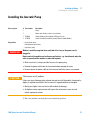
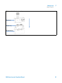
2 Ensure the power switch on the front of the module is OFF (switch stands
out).
HiVijhaVbe
EdlZghl^iX]
HZg^VacjbWZg
Figure 7
Front of module
3 At the rear of the module move the security lever to its maximum right
position.
4 Connect the power cable to the power connector at the rear of the module.
The security lever will prevent that the cover is opened while the power
cord is connected to the module.
32
1200 Series Isocratic Pump User Manual
Installing the Pump
Installing the Isocratic Pump
3
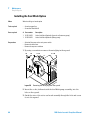
5 Connect the required interface cables to the rear of the isocratic pump, see
“Connecting Modules and Control Software” on page 34.
HZXjg^inaZkZg
Hadi[dg^ciZg[VXZ
WdVgY
6cVad\egZhhjgZ!
'bk$WVg
6E<GZbdiZ
GH"'('8
86C
<E>7
EdlZg
8dc[^\jgVi^dchl^iX]
Figure 8
Electrical Connections
6 Connect the capillary, solvent tube and waste tubing (see “Flow
Connections of the Isocratic Pump” on page 37).
7 Press power switch to turn on the module.
NOTE
The power switch stays pressed in and a green indicator lamp in the power switch is on
when the module is turned on. When the line power switch stands out and the green light
is off, the module is turned off.
8 Purge the isocratic pump (see “Priming and Purging the System” on
page 40).
NOTE
The pump was shipped with default configuration settings. To change these settings, refer
to sevice manual "Setting the 8-bit configuration switch".
1200 Series Isocratic Pump User Manual
33
3
Installing the Pump
Connecting Modules and Control Software
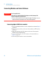
Connecting Modules and Control Software
WA R N I N G
Use of unsupplied cables
Using cables not supplied by Agilent Technologies can lead to damage of the
electronic components or personal injury.
➔ Never use cables other than the ones supplied by Agilent Technologies to ensure
proper functionality and compliance with safety or EMC regulations.
Connecting Agilent 1200 Series modules
1 Place the individual modules in a stack configuration as shown in Figure 5
on page 28.
2 Ensure the power switches on the front of the modules are OFF (switches
stand out).
3 Plug a CAN cable into the CAN connector at the rear of the respective
module (except vacuum degasser).
4 Connect the CAN cable to the CAN connector of the next module, see
Figure 6 on page 29.
5 Press in the power switches to turn on the modules.
34
1200 Series Isocratic Pump User Manual
Installing the Pump
Connecting Modules and Control Software
3
Connecting an Agilent 1200 Series Vacuum Degasser
1 Place the vacuum degasser in the stack of modules as shown in Figure 5 on
page 28.
2 Ensure the power switch on the front of the vacuum degasser is OFF
(switch stands out).
3 Plug an APG cable into the APG remote connector at the rear of the module.
4 Connect the APG cable to the APG remote connector of the pump, see
Figure 6 on page 29.
5 Press in the power switches to turn on the vacuum degasser.
NOTE
The AUX output allows the user to monitor the vacuum level in the degasser chamber.
Connecting control software and/or control modules
1 Ensure the power switches on the front of the modules in the stack are OFF
(switches stand out).
2 Plug a GPIB cable into the GPIB connector at one of the modules, preferably
at the detector (MUST for the DAD).
3 Connect the GPIB cable to the Agilent control software in use.
4 Plug a CAN cable into the CAN connector of the control module.
NOTE
Do not connect the Agilent control software or the control module with the vacuum
degasser.
5 Connect the CAN cable to the CAN connector of one of the modules.
6 Press in the power switches to turn on the modules.
1200 Series Isocratic Pump User Manual
35
3
Installing the Pump
Connecting Modules and Control Software
NOTE
36
The Agilent control software (e.g. ChemStation, EZChrom, OL, etc.) can be also be
connected to the system through a LAN cable, which requires the installation of a
LAN-board. For more information about connecting the control module or Agilent control
software refer to the respective user manual. For connecting the Agilent 1200 Series
equipment to non-Agilent 1200 Series equipment, see “Introduction to the Isocratic
Pump” on page 6.
1200 Series Isocratic Pump User Manual
3
Installing the Pump
Flow Connections of the Isocratic Pump
Flow Connections of the Isocratic Pump
Tools required
Two wrenches 1/4–5/16 inch for capillary connections
Parts required
Description
Other modules
Parts from accessory kit, see “Accessory Kit Contents G1311-68705” on page 27
Preparations
WA R N I N G
•
Pump is installed in the LC system.
When opening capillary or tube fittings solvents may leak out.
The handling of toxic and hazardous solvents and reagents can hold health risks.
➔ Please observe appropriate safety procedures (for example, goggles, safety gloves
and protective clothing) as described in the material handling and safety data sheet
supplied by the solvent vendor, especially when toxic or hazardous solvents are
used.
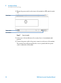
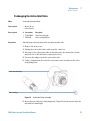
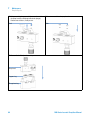
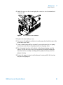
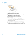
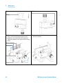
1 Remove the front cover by pressing the snap fasteners on both sides.
Figure 9
Removing the Front Corver
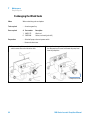
2 Place the solvent cabinet on top of the module.
1200 Series Isocratic Pump User Manual
37
3
Installing the Pump
Flow Connections of the Isocratic Pump
3 Place the bottle containing your solvent into the solvent cabinet and place
the bottle-head assembly into the bottle.
4 Connect the solvent tube from the bottle-head assembly to the inlet adapter
of the active inlet valve. Fix the tube in the clips of solvent cabinet and
isocratic pump.
5 Using a piece of sanding paper connect the waste tubing to the purge valve
and place it into your waste system.
6 If the pump is not part of a Agilent 1200 Series System stack or placed on
the bottom of a stack, connect the corrugated waste tube to the waste outlet
of the pump leak handling system.
7 Connect the pump outlet capillary (pump to injection device) to the outlet
of the purge valve.
38
1200 Series Isocratic Pump User Manual
Installing the Pump
Flow Connections of the Isocratic Pump
3
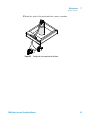
8 Purge your system before first use (see “Priming and Purging the
System” on page 40).
7diiaZ"]ZVYVhhZbWan
HdakZciijWZ
HdakZciXVW^cZi
IjWZXa^e
Ejg\ZkVakZ
Ejbe]ZVY
>caZiVYVeiZg
6Xi^kZ^caZikVakZ
LVhiZijW^c\
DjiaZiXVe^aaVgnidVjidhVbeaZg
Figure 10
Flow Connections of the Isocratic Pump
1200 Series Isocratic Pump User Manual
39
3
Installing the Pump
Priming and Purging the System
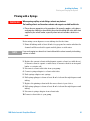
Priming and Purging the System
If a degasser is installed, it can be primed either by drawing solvent through
the degasser with a syringe or by pumping with the pump.
Priming the vacuum degasser or system with a syringe is recommended, when:
• vacuum degasser or connected tubings are used for the first time or vacuum
tubes are empty or
• changing to solvents that are immiscible with the solvent currently in the
vacuum tubes.
Priming the system by using the pump at high flow rate (3–5 ml/min) is
recommended, when:
• pumping system was turned off for a length of time (for example, overnight)
and if volatile solvent mixtures are used, or
• solvents have been changed.
40
1200 Series Isocratic Pump User Manual
3
Installing the Pump
Priming and Purging the System
Priming with a Syringe
WA R N I N G
When opening capillary or tube fittings solvents may leak out.
The handling of toxic and hazardous solvents and reagents can hold health risks.
➔ Please observe appropriate safety procedures (for example, goggles, safety gloves
and protective clothing) as described in the material handling and safety data sheet
supplied by the solvent vendor, especially when toxic or hazardous solvents are
used.
Before using a new degasser or new tubings for the first time:
1 Prime all tubings with at least 30 ml of iso-propanol no matter whether the
channels will be used with organic mobile phase or with water.
NOTE
If you are changing to a solvent that is immiscible with the solvent currently in the tubing
continue as follows:
2 Replace the current solvent with adequate organic solvent (see table above),
if current solvent is organic or with water, if current solvent is an inorganic
buffer or contains salt.
3 Disconnect solvent outlet tube from your pump.
4 Connect syringe adapter to solvent outlet tube.
5 Push syringe adapter onto syringe.
6 Pull syringe plunger to draw at least 30 ml of solvent through degasser and
tubing.
7 Replace the priming solvent with the new solvent of your choice.
8 Pull syringe plunger to draw at least 30 ml of solvent through degasser and
tubing.
9 Disconnect syringe adapter from solvent tube.
10 Connect solvent tube to your pump.
1200 Series Isocratic Pump User Manual
41
3
42
Installing the Pump
Priming and Purging the System
NOTE
When priming the vacuum degasser with a syringe the solvent is drawn through the
degasser tubes very quickly. The solvent at the degasser outlet will therefore not be fully
degassed. Pump for approximately 10 minutes with your selected flow rate before starting
any application. This will allow the vacuum degasser to properly degas the solvent in the
degasser tubes.
NOTE
The pump should never be used for priming empty tubings (never let the pump run dry). Use
the syringe to draw enough solvent for completely filling the tubings to the pump inlet
before continuing to prime with the pump.
1200 Series Isocratic Pump User Manual
Installing the Pump
Priming and Purging the System
3
Priming with the Pump
When the pumping system has been turned off for a certain time (for example,
overnight) oxygen will rediffuse into the solvent channel between the vacuum
degasser and the pump. Solvents containing volatile ingredients will slightly
lose these, if left in the degasser without flow for a prolonged period of time.
Therefore priming of the vacuum degasser and the pumping system is
required before starting an application.
1 Open the purge valve of your pump (by turning it counterclockwise) and set
flow rate to 3-5 ml/min.
2 Flush the vacuum degasser and all tubes with at least 30 ml of solvent.
3 Set flow to required value of your application and close the purge valve.
4 Pump for approximately 10 minutes before starting your application.
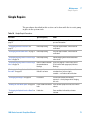
Table 7
Choice of Priming Solvents for Different Purposes
Activity
Solvent
Comments
After an installation
Isopropanol
Best solvent to flush air out of
the system
When switching between
reverse phase and normal
phase (both times)
Isopropanol
Best solvent to flush air out of
the system
After an installation
Ethanol or Methanol
Alternative to Isopropanol
(second choice) if no
Isopropanol is available
To clean the system when
using buffers
Bidistilled water
Best solvent to re-dissolve
buffer cristals
After a solvent change
Bidistilled water
Best solvent to re-dissolve
buffer cristals
After the installation of normal
phase seals (P/N 0905-1420)
Hexane + 5% Isopropanol
Good wetting properties
1200 Series Isocratic Pump User Manual
43
3
44
Installing the Pump
Priming and Purging the System
1200 Series Isocratic Pump User Manual
1200 Series Isocratic Pump User Manual
4
Using the Isocratic Pump
Hints for Successful Use of the Pump
Solvent Information
46
47
Prevent Blocking of Solvent Filters
48
Algae Growth in HPLC Systems 49
How to Prevent and/or Reduce the Algae Problem
Agilent Technologies
50
45
4
Using the Isocratic Pump
Hints for Successful Use of the Pump
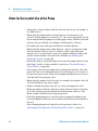
Hints for Successful Use of the Pump
• Always place solvent cabinet with the solvent bottle on top of the pump (or
at a higher level).
• When using the pump without vacuum degasser, shortly degass your
solvents. Vacuum pump the solvents for 15 – 30 s (in an appropriate vessel)
before using them in the pump. If possible apply solvent conditions that will
decrease the gas solubility (for example, warming up the solvents).
• For highest precision and reproducibility use vacuum degasser.
• When using the pump with vacuum degasser – before operating the pump
flush the degasser with at least two volumes (30 ml), especially when
turned off for a certain length of time (for example, during the night) and
volatile solvent mixtures are used in the channels (see “Priming and
Purging the System” on page 40).
• Prevent blocking of solvent inlet filters (never use the pump without solvent
inlet filter). Growth of algae should be avoided (see “Prevent Blocking of
Solvent Filters” on page 48).
• Check purge valve frit and column frit in regular time intervals. A blocked
purge valve frit can be identified by black or yellow layers on its surface or
by a pressure greater than 10 bar, when pumping distilled water at a rate of
5 ml/min with an open purge valve.
• When using the pump at low flow rates (for example, 0.2 ml/min) check all
1/16 inch fittings for any signs of leaks.
• Always exchange the purge valve frit, too, when exchanging the seals.
• When using buffer solutions, flush the system with water before switching
it off. The seal wash option should be used when buffer solutions of 0.1
Molar or higher will be used for long time periods.
• Check the pump plungers for scratches when changing the plunger seals.
Scratched plungers will lead to micro leaks and will decrease the lifetime of
the seal.
• After changing plunger seals apply the seal wear-in procedure (see
“Exchanging the Pump Seals and Seal Wear-in Procedure” on page 83).
46
1200 Series Isocratic Pump User Manual
4
Using the Isocratic Pump
Solvent Information
Solvent Information
Always filter solvents through 0.4 µm filters, small particles can permanently
block the capillaries and valves. Avoid the use of the following steel-corrosive
solvents:
• Solutions of alkali halides and their respective acids (for example, lithium
iodide, potassium chloride, and so on).
• High concentrations of inorganic acids like sulfuric and nitric acid,
especially at higher temperatures (replace, if your chromatography method
allows, by phosphoric acid or phosphate buffer which are less corrosive
against stainless steel).
• Halogenated solvents or mixtures which form radicals and/or acids, for
example:
2CHCl3 + O2 →2COCl2 + 2HCl
This reaction, in which stainless steel probably acts as a catalyst, occurs
quickly with dried chloroform if the drying process removes the stabilizing
alcohol.
• Chromatographic grade ethers, which can contain peroxides (for example,
THF, dioxane, di-isopropylether). Such ethers should be filtered through
dry aluminium oxide which adsorbs the peroxides.
• Mixtures of carbon tetrachloride with 2-propanol or THF dissolve stainless
steel.
1200 Series Isocratic Pump User Manual
47
4
Using the Isocratic Pump
Prevent Blocking of Solvent Filters
Prevent Blocking of Solvent Filters
Contaminated solvents or algae growth in the solvent bottle will reduce the
lifetime of the solvent filter and will influence the performance of the module.
This is especially true for aqueous solvents or phosphate buffers (pH 4 to 7).
The following suggestions will prolong lifetime of the solvent filter and will
maintain the performance of the module.
• Use a sterile, if possible amber, solvent bottle to slow down algae growth.
• Filter solvents through filters or membranes that remove algae.
• Exchange solvents every two days or refilter.
• If the application permits add 0.0001-0.001M sodium azide to the solvent.
• Place a layer of argon on top of your solvent.
• Avoid exposure of the solvent bottle to direct sunlight.
NOTE
48
Never use the system without solvent filter installed.
1200 Series Isocratic Pump User Manual
4
Using the Isocratic Pump
Algae Growth in HPLC Systems
Algae Growth in HPLC Systems
The presence of algae in HPLC systems can cause a variety of problems that
may be incorrectly diagnosed as instrument or application problems. Algae
grow in aqueous media, preferably in a pH range of 4-8. Their growth is
accelerated by buffers, for example phosphate or acetate. Since algae grow
through photosynthesis, light will also stimulate their growth. Even in distilled
water small-sized algae grow after some time.
Instrumental Problems Associated With Algae
Algae deposit and grow everywhere within the HPLC system causing:
• Deposits on ball valves, inlet or outlet, resulting in unstable flow or total
failure of the pump.
• Small pore solvent inlet filters to plug, resulting in unstable flow or total
failure of the pump.
• Small pore high pressure solvent filters, usually placed before the injector
to plug resulting in high system pressure.
• Column filters to plug giving high system pressure.
• Flow cell windows of detectors to become dirty resulting in higher noise
levels (since the detector is the last module in the flow path, this problem is
less common).
Symptoms Observed with the Agilent 1200 Series HPLC
In contrast to the HP 1090 and HP 1050 Series HPLC systems which use
helium degassing, algae have a better chance to grow in systems such as the
Agilent 1200 Series where helium is not used for degassing (most algae need
oxygen and light for growth).
The presence of algae in the Agilent 1200 Series can cause the following to
occur:
• PTFE frits, part number 01018-22707, (purge valve assembly) and column
filter blockage causing increased system pressure. Algae appear as white or
yellowish-white deposits on filters. Typically black particles from the
1200 Series Isocratic Pump User Manual
49
4
Using the Isocratic Pump
Algae Growth in HPLC Systems
normal wear of the piston seals do not cause the PTFE frits to block over
short-term usage. Please refer to the section “Exchanging the Purge Valve
Frit or the Purge Valve” on page 79 in this manual.
• Short lifetime of solvent filters (bottle head assembly). A blocked solvent
filter in the bottle, especially when only partly blocked, is more difficult to
identify and may show up as gradient performance problems, intermittent
pressure fluctuations etc.
• Algae growth may also be the possible source for failures of the ball valves
and other components in the flow path.
How to Prevent and/or Reduce the Algae Problem
• Always use freshly prepared solvents, especially use demineralized water
which was filtered through about 0.2 µm filters.
• Never leave mobile phase in the instrument for several days without flow.
• Always discard “old” mobile phase.
• Use the amber solvent bottle (part number 9301-1450) supplied with the
instrument for your aqueous mobile phase.
• If possible add a few mg/l sodium azide or a few percent organic solvent to
the aqueous mobile phase.
50
1200 Series Isocratic Pump User Manual
1200 Series Isocratic Pump User Manual
5
Optimiziming Performance
When to Use a Vacuum Degasser
52
When to use the Seal Wash Option
When to Use Alternative Seals
53
54
Optimize the Compressibility Compensation Setting
Agilent Technologies
55
51
5
Optimiziming Performance
When to Use a Vacuum Degasser
When to Use a Vacuum Degasser
The pump does not necessarily require degassing. But for the following
conditions the vacuum degasser is recommended:
• if your detector is used with maximum sensitivity in the low UV wavelength
range,
• if your application requires highest injection precision, or
• if your application requires highest retention-time reproducibility
(mandatory at flow rates below 0.5 ml/min).
Operational Hints for the Vacuum Degasser
If you are using the vacuum degasser for the first time, if the vacuum degasser
was switched off for any length of time (for example, overnight), or if the
vacuum degasser lines are empty, you should prime the vacuum degasser
before running an analysis.
The vacuum degasser can be primed either by drawing solvent through the
degasser with a syringe or by pumping with the pump.
Priming the degasser with a syringe is recommended, when:
• vacuum degasser is used for the first time, or vacuum tubes are empty, or
• changing to solvents that are immiscible with the solvent currently in the
vacuum tubes.
Priming the vacuum degasser by using the pump at high flow rate 140 x 345 x
435 mm (5.5 x 13.5 x 17 inches)is recommended, when:
• pump was turned off for a length of time (for example, during night) and
volatile solvent mixtures are used, or
• solvents have been changed.
For more information see the User Manual for the Agilent 1200 Series vacuum
degasser.
52
1200 Series Isocratic Pump User Manual
5
Optimiziming Performance
When to use the Seal Wash Option
When to use the Seal Wash Option
Highly-concentrated buffer solutions will reduce the lifetime of the seals and
plungers in your pump. The seal wash option allows to maintain the seal
lifetime by flushing the back side of the seal with a wash solvent.
The seal wash option is strongly recommended when buffer concentrations of
0.1 Molar or higher will be used for long time periods in the pump.
The seal wash option can be ordered by quoting part number 01018-68722 (kit
contains all parts needed for one pump head). The active seal wash option kit
can be ordered by quoting part number G1311-68711.
The seal wash option comprises a support ring, secondary seal, gasket and
seal keeper for both plunger sides. A wash bottle filled with water
/isopropanol (90/10) should be placed above the pump in the solvent cabinet
and gravity will maintain a flow through the pump head removing all possible
buffer crystals from the back of the pump seal. For the active seal wash a
peristaltic pump is pumping the solvent through the pump head.
NOTE
Running dry is the worst case for a seal and drastically reduces its lifetime. The seal will
build up sticky layers on the surface of the plunger. These sticky layers will also reduce the
lifetime of the primary seal. Therefore the tubes of the wash option should always be filled
with solvent to prolong the lifetime of the wash seal. Always use a mixture of bidistilled
water (90 %) and isopropanol (10 %) as wash solvent. This mixture prevents bacteria
growth in the wash bottle and reduces the surface tension of the water.
For information on the installation of the active seal wash option refer to
“Installing the Seal Wash Option” on page 88.
1200 Series Isocratic Pump User Manual
53
5
Optimiziming Performance
When to Use Alternative Seals
When to Use Alternative Seals
The standard seal for the pump can be used for most applications. However
applications that use normal phase solvents (for example, hexane) are not
suited for the standard seal and require a different seal when used for a longer
time in the pump.
For applications that use normal phase solvents (for example, hexane) we
recommend the use of the polyethylene seals, part number 0905-1420 (pack of
2). These seals have less abrasion compared to the standard seals.
NOTE
54
Polyethylene seals have a limited pressure range 0–200 bar. When used above 200 bar their
lifetime will be significantly reduced. DO NOT apply the seal wear-in procedure performed
with new standard seals at 400 bar.
1200 Series Isocratic Pump User Manual
5
Optimiziming Performance
Optimize the Compressibility Compensation Setting
Optimize the Compressibility Compensation Setting
The compressibility compensation default setting is 100 × 10-6 /bar for the
pump. This setting represents an average value. Under normal conditions the
default setting reduces the pressure pulsation to values (below 1% of system
pressure) that will be sufficient for most applications and for all gradient
analyses. For applications using sensitive detectors, the compressibility
settings can be optimized by using the values for the various solvents
described in Table 8 on page 56. If the solvent in use is not listed in the
compressibility tables, when using isocratic mixtures of solvents and if the
default settings are not sufficient for your application the following procedure
can be used to optimize the compressibility settings.
NOTE
When using mixtures of solvents it is not possible to calculate the compressibility of the
mixture by interpolating the compressibility values of the pure solvents used in that mixture
or by applying any other calculation. In these cases the following empirical procedure has
to be applied to optimize your compressibility setting.
1 Start the pump with the required flow rate.
2 Before starting the optimization procedure, the flow must be stable. Use
degassed solvent only. Check the tightness of the system with the pressure
test (via Lab Monitoring and Diagonistic Software (LMD)).
3 Your pump must be connected to a control software (e.g. ChemStation,
EZChrom, OL, etc.) or handheld controller with which the pressure and
%-ripple can be monitored, otherwhise connect a signal cable between the
pressure output of the pump and a recording device (for example, 339X
integrator) and set parameters.
Zero 50%
Att 2^3 Chart
Speed 10 cm/min
4 Start the recording device with the plot mode.
5 Starting with a compressibility setting of 10 × 10-6 /bar increase the value
in steps of 10. Re-zero the integrator as required. The compressibility
compensation setting that generates the smallest pressure ripple is the
optimum value for your solvent composition.
1200 Series Isocratic Pump User Manual
55
5
Optimiziming Performance
Optimize the Compressibility Compensation Setting
Table 8
56
Solvent Compressibility
Solvent (pure)
Compressibility (10-6/bar)
Acetone
126
Acetonitrile
115
Benzene
95
Carbon tetrachloride
110
Chloroform
100
Cyclohexane
118
Ethanol
114
Ethyl acetate
104
Heptane
120
Hexane
150
Isobutanol
100
Isopropanol
100
Methanol
120
1-Propanol
100
Toluene
87
Water
46
1200 Series Isocratic Pump User Manual
1200 Series Isocratic Pump User Manual
6
Troubleshooting and Diagnostics
Agilent Lab Advisor Software
58
Overview of the Pump’s Indicators and Test Functions
59
Status Indicators 60
Power Supply Indicator 60
Instrument Status Indicator 61
User Interfaces
62
Agilent Technologies
57
6
Troubleshooting and Diagnostics
Agilent Lab Advisor Software
Agilent Lab Advisor Software
The Agilent Lab Advisor Software is a standalone product that can be used
with or without data system. Agilent Lab Advisor helps to manage the lab for
high quality chromatographic results and can monitor in real time a single
Agilent LC or all the Agilent GCs and LCs configured on the lab intranet.
Agilent Lab Advisor provides diagnostic capabilities for all Agilent 1200 Series
HPLC modules. This includes tests and calibrations procedures as well as the
different injector steps to perform all the maintenance routines.
Agilent Lab Advisor also allows users to monitor the status of their LC
instruments. The Early Maintenance Feedback (EMF) feature helps to carry
out preventive maintenance. In addition, users can generate a status report for
each individual LC instrument. The tests and diagnostic features as provided
by the Agilent Lab Advisor Software may differ from the descriptions in this
manual. For details refer to the Agilent Lab Advisor help files.
This manual provides lists with the names of Error Messages, Not Ready
messages, and other common issues.
58
1200 Series Isocratic Pump User Manual
6
Troubleshooting and Diagnostics
Overview of the Pump’s Indicators and Test Functions
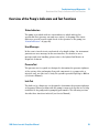
Overview of the Pump’s Indicators and Test Functions
Status Indicators
The pump is provided with two status indicators which indicate the
operational state (prerun, run, and error states) of the pump. The status
indicators provide a quick visual check of the operation of the pump (see
“Status Indicators” on page 60).
Error Messages
In the event of an electronic, mechanical or hydraulic failure, the instrument
generates an error message in the user interface. For details on error
messages and error handling, please refer to the Agilent Lab Monitor &
Diagnostic Software.
Pressure Test
The pressure test is a quick test designed to determine the pressure tightness
of the system. After exchanging flow path components (e.g. pump seals or
injection seal), use this test to verify the system is pressure tight up to 400 bar
(see Service Manual).
Leak Test
The leak test is a diagnostic test designed to determine the pressure tightness
of the pump. When a problem with the pump is suspected, use this test to help
troubleshoot the pump and its pumping performance. The following sections
describe these functions in detail (see Service Manual ).
1200 Series Isocratic Pump User Manual
59
6
Troubleshooting and Diagnostics
Status Indicators
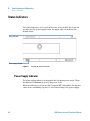
Status Indicators
Two status indicators are located on the front of the module. The lower left
one indicates the power supply status, the upper right one indicates the
module status.
HiVijh^cY^XVidg
EdlZghjeean^cY^XVidg
Figure 11
Location of Status Indicators
Power Supply Indicator
The power supply indicator is integrated into the main power switch. When
the indicator is illuminated (green) the power is ON.
When the indicator is off, the module is turned OFF. Otherwhise check power
connections, availability of power or check functioning of the power supply.
60
1200 Series Isocratic Pump User Manual
Troubleshooting and Diagnostics
Status Indicators
6
Instrument Status Indicator
The instrument status indicator indicates one of four possible instrument
conditions:
• When the status indicator is OFF (and power switch light is ON), the
module is in aprerun condition, and is ready to begin an analysis.
• A green status indicator, indicates the module is performing an analysis
(run mode).
• A yellow indicator indicates a not-ready condition. The module is in a
not-ready state when it is waiting for a specific condition to be reached or
completed (for example, immediately after changing a setpoint), or while a
self-test procedure is running.
• An error condition is indicated when the status indicator is red. An error
condition indicates the module has detected an internal problem which
affects correct operation of the module. Usually, an error condition requires
attention (for example, leak, defective internal components). An error
condition always interrupts the analysis.
• A flashing yellow status indicator indicates that the module is in its
resident mode. Call your local service provider for assistance upon
observing this error condition.
• A flashing red status indicator indicates a severe error during the startup
procedure of the module. Call your local service provider for assistance
upon observing this error condition.
1200 Series Isocratic Pump User Manual
61
6
Troubleshooting and Diagnostics
User Interfaces
User Interfaces
Depending on the User Interface, the available test vary. Some descriptions
are only available in the Service Manual.
Table 9
62
Test Functions available vs. User Interface
Test
ChemStation
Instant Pilot
G4208A
Control Module
G1323B
Agilent Lab
Monitor &
Diagnostic
Software
Pressure Test
Yes
Yes
Yes
Yes
Leak Test
Yes
Yes
Yes
Yes
1200 Series Isocratic Pump User Manual
1200 Series Isocratic Pump User Manual
7
Maintenance
Introduction to Maintenance and Repair
Simple Repairs 64
Exchanging Internal Parts 64
Warnings and Cautions 65
Using the ESD Strap 66
Cleaning the Module 66
Early Maintenance Feedback (EMF)
EMF Counters 67
Using the EMF Counters 68
Overview of Maintenance and Repair
64
67
69
Simple Repairs 71
Checking and Cleaning the Solvent Filter 72
Exchanging the Active Inlet Valve 73
Exchanging the Active Inlet Valve Cartridge 75
Exchanging the Outlet Ball Valve 77
Exchanging the Purge Valve Frit or the Purge Valve 79
Removing the Pump Head Assembly 82
Exchanging the Pump Seals and Seal Wear-in Procedure
Exchanging the Plungers 86
Installing the Seal Wash Option 88
Exchanging the Wash Seals 92
Reinstalling the Pump Head Assembly 95
Exchanging the Optional Interface Board 96
Replacing the Module’s Firmware 97
Agilent Technologies
83
63
7
Maintenance
Introduction to Maintenance and Repair
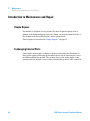
Introduction to Maintenance and Repair
Simple Repairs
The module is designed for easy repair. The most frequent repairs such as
plunger seal change and purge valve frit change can be done from the front of
the module with the module in place in the system stack.
These repairs are described in “Simple Repairs” on page 71.
Exchanging Internal Parts
Some repairs may require exchange of defective internal parts. Exchange of
these parts requires removing the module from the stack, removing the covers,
and disassembling the module. The security lever at the power input socket
prevents that the module cover is taken off when line power is still connected.
64
1200 Series Isocratic Pump User Manual
7
Maintenance
Introduction to Maintenance and Repair
Warnings and Cautions
WA R N I N G
Module is partially energized when switched off, as long as the power cord is
plugged in.
Repair work at the module can lead to personal injuries, e.g. shock hazard, when the
cover is opened and the module is connected to power.
➔ Make sure that it is always possible to access the power plug.
➔ Remove the power cable from the instrument before opening the cover.
➔ Do not connect the power cable to the Instrument while the covers are removed.
WA R N I N G
Sharp metal edges
Sharp-edged parts of the equipment may cause injuries.
➔ To prevent personal injury, be careful when getting in contact with sharp metal
areas.
WA R N I N G
When opening capillary or tube fittings solvents may leak out.
The handling of toxic and hazardous solvents and reagents can hold health risks.
➔ Please observe appropriate safety procedures (for example, goggles, safety gloves
and protective clothing) as described in the material handling and safety data sheet
supplied by the solvent vendor, especially when toxic or hazardous solvents are
used.
CAUTION
Electronic boards are static sensitive and should be handled with care so as not to
damage them. Touching electronic boards and components can cause electrostatic
discharge (ESD).
ESD can damage electronic boards and components.
➔ Be sure to hold the board by the edges and do not touch the electrical components.
Always use an ESD protection (for example, an ESD wrist strap) when handling
electronic boards and components.
1200 Series Isocratic Pump User Manual
65
7
Maintenance
Introduction to Maintenance and Repair
Using the ESD Strap
Electronic boards are sensitive to electronic discharge (ESD). In order to
prevent damage, always use an ESD strap when handling electronic boards
and components.
1 Unwrap the first two folds of the band and wrap the exposed adhesive side
firmly around your wrist.
2 Unroll the rest of the band and peel the liner from the copper foil at the
opposite end.
3 Attach the copper foil to a convenient and exposed electrical ground.
Figure 12
Using the ESD Strap
Cleaning the Module
WA R N I N G
Liquid dripping into the electronic compartment of your module.
Liquid in the module electronics can cause shock hazard and damage the module.
➔ Do not use an exessively damp cloth during cleaning.
➔ Drain all solvent lines before opening any fittings.
The module case should be kept clean. Cleaning should be done with a soft
cloth slightly dampened with water or a solution of water and a mild
detergent. Do not use an excessively damp cloth that liquid can drip into the
module.
66
1200 Series Isocratic Pump User Manual
Maintenance
Early Maintenance Feedback (EMF)
7
Early Maintenance Feedback (EMF)
Maintenance requires the exchange of components in the flow path which are
subject to mechanical wear or stress. Ideally, the frequency at which
components are exchanged should be based on the intensity of usage of the
instrument and the analytical conditions, and not on a predefined time
interval. The early maintenance feedback (EMF) feature monitors the usage of
specific components in the instrument, and provides feedback when the
user-settable limits have been exceeded. The visual feedback in the user
interface provides an indication that maintenance procedures should be
scheduled.
EMF Counters
The pump provides a series of EMF counters for the pump head. Each counter
increments with pump use, and can be assigned a maximum limit which
provides visual feedback in the user interface when the limit is exceeded. Each
counter can be reset to zero after maintenance has been done. The pump
provides the following EMF counters:
• Pump Liquimeter
• Pump seal wear
Pump Liquimeter
The pump liquimeter displays the total volume of solvent pumped by the pump
head since the last reset of the counters. The pump liquimeter can be assigned
an EMF (maximum) limit. When the limit is exceeded, the EMF flag in the user
interface is displayed.
Seal Wear Counters
The seal wear counters display a value derived from pressure and flow (both
contribute to seal wear). The values increment with pump usage until the
counters are reset after seal maintenance. Both seal wear counters can be
assigned an EMF (maximum) limit. When the limit is exceeded, the EMF flag in
the user interface is displayed.
1200 Series Isocratic Pump User Manual
67
7
Maintenance
Early Maintenance Feedback (EMF)
Using the EMF Counters
The user-settable EMF limits for the EMF counters enable the early
maintenance feedback to be adapted to specific user requirements. The wear
of pump components is dependent on the analytical conditions, therefore, the
definition of the maximum limits need to be determined based on the specific
operating conditions of the instrument.
Setting the EMF Limits
The setting of the EMF limits must be optimized over one or two maintenance
cycles. Initially, no EMF limit should be set. When performance indicates
maintenance is necessary, take note of the values displayed by pump
liquimeter and seal wear counters. Enter these values (or values slightly less
than the displayed values) as EMF limits, and then reset the EMF counters to
zero. The next time the EMF counters exceed the new EMF limits, the EMF flag
will be displayed, providing a reminder that maintenance needs to be
scheduled.
68
1200 Series Isocratic Pump User Manual
Maintenance
Overview of Maintenance and Repair
7
Overview of Maintenance and Repair
Figure 13 on page 69 shows the main assemblies of the isocratic pump. The
pump head and its parts do require normal maintenance (for example, seal
exchange) and can be accessed from the front (simple repairs). Replacing
internal parts will require to remove the isocratic pump from its stack and to
open the top cover.
+
,
*
)
(
'
.
&
&%
Figure 13
Overview of Repair Procedures
1
Active inlet valve, “Exchanging the Active Inlet Valve” on page 73
2
Purge valve, “Exchanging the Purge Valve Frit or the Purge Valve” on page 79
1200 Series Isocratic Pump User Manual
69
7
70
Maintenance
Overview of Maintenance and Repair
3
Outlet ball valve, “Exchanging the Outlet Ball Valve” on page 77
4
Pump head, “Removing the Pump Head Assembly” on page 82
5
Pump drive
6
Power supply
7
LPM board
8
Fan
9
Damping unit
10
Leak sensor
1200 Series Isocratic Pump User Manual
Maintenance
Simple Repairs
7
Simple Repairs
The procedures described in this section can be done with the isocratic pump
in place in the system stack.
Table 10
Simple Repair Procedures
Procedure
Typical Frequency
Notes
“Checking and Cleaning the Solvent Filter” on
page 72
If solvent filter is blocked
Gradient performance problems, intermittent
pressure fluctuations
“Exchanging the Active Inlet Valve” on
page 73
If internally leaking
Pressure ripple unstable, run leak test for
verification
“Exchanging the Outlet Ball Valve” on page 77 If internally leaking
Pressure ripple unstable, run leak test for
verification
“Exchanging the Purge Valve Frit or the Purge
Valve” on page 79
If internally leaking
Solvent dripping out of waste outlet when
valve closed
“Exchanging the Purge Valve Frit or the Purge
Valve” on page 79
If the frit shows indication
of contamination or
blockage
A pressure drop of > 10 bar across the frit
(5 ml/min H2O with purge open) indicates
blockage
“Exchanging the Pump Seals and Seal Wear-in
Procedure” on page 83
If pump performance
indicates seal wear
Leaks at lower pump head side, unstable
retention times, pressure ripple
unstable — run leak test for verification
“Exchanging the Plungers” on page 86
If scratched
Seal life time shorter than normally
expected — check plungers while changing
the seals
“Installing the Seal Wash Option” on page 88
If seals show indication of
leaks
Leaks at lower pump head side, loss of wash
solvent
“Exchanging the Optional Interface Board” on
page 96
If defective
Error condition, indicated by red status
indicator
1200 Series Isocratic Pump User Manual
71
7
Maintenance
Simple Repairs
Checking and Cleaning the Solvent Filter
CAUTION
Small particles can permanently block the capillaries and valves of the module.
Damage of the module.
➔ Always filter solvents.
➔ Never use the module without solvent inlet filter.
NOTE
If the filter is in good condition the solvent will freely drip out of the solvent tube
(hydrostatic pressure). If the solvent filter is partly blocked only very little solvent will drip
out of the solvent tube.
Cleaning the Solvent Filter
When
If solvent filter is blocked
Parts required
#
Description
Concentrated nitric acid (35%)
Bidistilled water
1
Preparations
•
Beaker
Remove solvent inlet tube from the adapter at the AIV
1 Remove the blocked solvent filter from the bottle-head assembly and place
it in a beaker with concentrated nitric acid (35%) for one hour.
2 Thoroughly flush the filter with bidistilled water (remove all nitric acid,
some capillary columns can be damaged by nitric acid).
3 Replace the filter.
72
1200 Series Isocratic Pump User Manual
Maintenance
Simple Repairs
7
Exchanging the Active Inlet Valve
When
If internally leaking (backflow)
Tools required
•
•
Parts required
#
Part number
Description
1
G1312-60025
Active inlet valve body
1
5062-8562
Valve cartridge (400 bar)
Preparations
Wrench 14 mm
Pair of Tweezers
Switch off pump at the main power switch and unplug the power cable
1 Remove the front cover.
2 Unplug the active inlet valve cable from the connector.
3 Disconnect the solvent inlet tube at the inlet valve (be aware that solvent
may leak out of the tube due to hydrostatic flow).
4 Unscrew the adapter from the active inlet valve.
5 Using a 14 mm wrench loosen the active inlet valve and remove the valve
from pump head.
6Xi^kZ^caZikVakZWdYn
KVakZXVgig^Y\Z
Figure 14
Active Inlet Valve Assembly
6 Insert the new valve into the pump head. Using the 14 mm wrench turn the
nut until it is hand tight.
1200 Series Isocratic Pump User Manual
73
7
Maintenance
Simple Repairs
7 Position the valve so that the solvent inlet tube connection points towards
the front.
8 Using the 14 mm wrench tighten the nut by turning the valve in its final
position (not more than a quarter turn).
9 Reconnect the adapter at the active inlet valve.
10 Reconnect the solvent inlet tube to the adapter. Reconnect the active inlet
valve cable to the connector in the Z-panel.
11 Reinstall the front cover.
NOTE
74
After an exchange of the valve it may take several ml of pumping with the solvent used in
the current application, before the flow stabilizes at a %-ripple as low as it used to be when
the system was still working properly.
1200 Series Isocratic Pump User Manual
Maintenance
Simple Repairs
7
Exchanging the Active Inlet Valve Cartridge
When
If internally leaking (backflow)
Tools required
•
•
Parts required
#
Part number
Description
1
G1312-60025
Active inlet valve body
1
5062-8562
Valve cartridge (400 bar)
Preparations
Wrench 14 mm
Pair of Tweezers
Switch off pump at the main power switch and unplug the power cable
HdakZci^caZiijWZ
8Ve^aaVgn
ejbeid^c_ZXi^dcYZk^XZ
8dccZXidg
6Xi^kZ^caZikVakZ
6Xi^kZ^caZikVakZXVWaZ
6YVeiZg
Figure 15
Exchanging the Active Inlet Valve
1 Remove the front cover.
2 Unplug the active inlet valve cable from the connector.
1200 Series Isocratic Pump User Manual
75
7
Maintenance
Simple Repairs
3 Disconnect the solvent inlet tube at the inlet valve (be aware that solvent
may leak out of the tube due to hydrostatic flow).
4 Unscrew the adapter from the active inlet valve.
5 Using a 14 mm wrench loosen the active inlet valve and remove the valve
from pump head.
6 Using a pair of tweezers remove the valve cartridge from the actuator
assembly.
7 Before inserting the new valve cartridge clean the area in the actuator
assembly. Flush the cartridge area thoroughly with alcohol.
8 Insert a new valve cartridge into the actuator assembly (make sure the
valve cartridge is fully inserted into the actuator assembly).
9 Insert the valve into the pump head. Using the 14 mm wrench turn the nut
until it is hand tight.
10 Position the valve so that the solvent inlet tube connection points towards
the front.
11 Using the 14 mm wrench tighten the nut by turning the valve in its final
position (not more than a quarter turn).
12 Reconnect the adapter at the active inlet valve.
13 Reconnect the solvent inlet tube to the adapter. Reconnect the active inlet
valve cable to the connector in the Z-panel.
14 Reinstall the front cover.
NOTE
76
After an exchange of the valve cartridge it may take several ml of pumping with the solvent
used in the current application, before the flow stabilizes at a %-ripple as low as it used to
be when the system was still working properly.
1200 Series Isocratic Pump User Manual
Maintenance
Simple Repairs
7
Exchanging the Outlet Ball Valve
When
If internally leaking
Tools required
•
•
Parts required
#
Part number
Description
1
G1311-60012
Outlet ball valve
Preparations
NOTE
•
•
Wrench 1/4 inch
Wrench 14 mm
Switch off pump at the main power switch
Remove the front cover
Before exchanging the outlet ball valve you can try to clean it in a sonic bath for
5 – 10 minutes. Place the valve in an upright position in a small beaker with alcohol.
1 Using a 1/4 inch wrench disconnect the valve capillary from the outlet ball
valve.
2 Using the 14 mm wrench loosen the valve and remove it from the pump
body.
3 Check that the new valve is assembled correctly and that the gold seal is
present (if the gold seal is deformed, it should be replaced).
KVakZWdYn
<daYhZVa
EaVhi^XXVe
Figure 16
Outlet Ball Valve Parts
1200 Series Isocratic Pump User Manual
77
7
Maintenance
Simple Repairs
4 Reinstall the outlet ball valve and tighten the valve.
5 Reconnect the valve capillary.
KVakZXVe^aaVgn
DjiaZiWVaakVakZ
Figure 17
78
Exchanging the Outlet Ball Valve
1200 Series Isocratic Pump User Manual
Maintenance
Simple Repairs
7
Exchanging the Purge Valve Frit or the Purge Valve
When
Frit – when plunger seals are exchanged or when contaminated or blocked (pressure drop of
> 10 bar across the frit at a flow rate of 5 ml/min of H20 with purge valve opened)
Purge valve – if internally leaking
Tools required
•
•
•
Parts required
#
Part number
Description
5
01018-22707
PTFE frit (pack of 5)
1
G1311-60009
Purge valve
Preparations
•
•
Wrench 1/4 inch
Wrench 14 mm
Pair of tweezers or toothpick
Switch off pump at the main power switch
Remove the front cover
1 Using a 1/4 inch wrench disconnect the pump outlet capillary at the purge
valve.
2 Disconnect the waste tube. Beware of leaking solvents due to hydrostatic
pressure.
3 Using the 14 mm wrench unscrew the purge valve and remove it.
4 Remove the plastic cap with the gold seal from the purge valve.
1200 Series Isocratic Pump User Manual
79
7
Maintenance
Simple Repairs
5 Using a pair of tweezers or a toothpick remove the frit.
KVakZWdYn
EI;:[g^i
<daYhZVa
EaVhi^XXVe
Figure 18
Purge Valve Parts
6 Place a new frit into the purge valve with the orientation of the frit as
shown above.
7 Reinstall the cap with the gold seal.
NOTE
Before reinstallation always check the gold seal. A deformed seal should be exchanged.
8 Insert the purge valve into the pump head and locate the pump outlet
capillary and the waste tube as shown in Figure 19 on page 81.
80
1200 Series Isocratic Pump User Manual
Maintenance
Simple Repairs
7
9 Tighten the purge valve and reconnect outlet capillary and waste tubing.
Ejg\ZkVakZ
DjiaZiXVe^aaVgn
LVhiZijWZ
Figure 19
Exchanging the Purge Valve
1200 Series Isocratic Pump User Manual
81
7
Maintenance
Simple Repairs
Removing the Pump Head Assembly
When
•
•
•
Exchanging the seals
Exchanging the plungers
Exchanging seals of the seal wash option
Tools required
•
•
Wrench 1/4 inch
4-mm hexagonal key
Preparations
Switch off pump at the main power switch and unplug the power cable
CAUTION
Damage of the pump drive
Starting the pump when the pump head is removed may damage the pump drive.
➔ Never start the pump when the pump head is removed.
1 Remove the front cover.
2 Disconnect the Active Inlet Valve cable.
3 Using a 1/4 inch wrench remove the outlet capillary.
Ejbe]ZVYhXgZlh
4 Disconnect the capillary from the Outlet Ball Valve.
5 Remove the waste tubing and disconnect the Active Inlet Valve tubing.
6 Remove the capillary at the bottom of the Pumphead.
7 Using a 4 mm hexagonal key, stepwise loosen the two Pumphead screws and
remove the Pumphead from the Pump Drive.
82
1200 Series Isocratic Pump User Manual
Maintenance
Simple Repairs
7
Exchanging the Pump Seals and Seal Wear-in Procedure
When
Seal leaking, if indicated by the results of the leak test.
Tools required
•
•
Parts required
#
Part number
Description
2
5063-6589
standard Seals (pack of 2)or
Preparations
Wrench 1/4 inch
4-mm hexagonal key
0905-1420
Seals (pack of 2) for normal phase applications
1
0100-1847
For the seal wear-in procedure: Adapter AIV to inlet tube
1
5022-2159
Restriction capillary
•
•
•
Switch off pump at the main power switch
Remove the front cover
“Removing the Pump Head Assembly” on page 82
1 Place the pump head on a flat surface. Loosen the lock
screw (two revolutions) and while holding the lower half
of the assembly carefully pull the pump head away from
the plunger housing.
Ejbe]ZVY
2 Remove the support rings from the plunger housing and
lift the housing away from the plungers.
Hjeedgig^c\
AdX`hXgZl
Eajc\Zg]djh^c\
Eajc\Zg]djh^c\
1200 Series Isocratic Pump User Manual
Eajc\Zg
83
7
Maintenance
Simple Repairs
3 Using one of the plungers carefully remove the seal from
4 Insert new seals into the pump head.
the pump head (be careful not to break the plunger).
Remove wear retainers, if still present.
HZVa
HZVah
5 Reassemble the Pumphead assembly.
Ejbe]ZVY
Hjeedgig^c\
Eajc\Zg]djh^c\
84
1200 Series Isocratic Pump User Manual
7
Maintenance
Simple Repairs
Seal Wear-in Procedure
NOTE
This procedure is required for standard seals only (5063-6589), but it will definitely damage
the normal phase application seals (0905-1420).
1 Place a bottle with 100 ml of isopropanol in the solvent cabinet and place
the tubing (including bottle head assembly) of the pump head that is
supposed to be worn-in into the bottle.
2 Screw the adapter (0100-1847) to the AIV and connect the inlet tube from
the bottle head directly to it.
3 Connect the restriction capillary (5022-2159) to the purge valve. Insert its
other end into a waste container.
4 Open the purge valve and purge the system for 5 minutes with isopropanol
at a flow rate of 2 mL/min.
5 Close the purge valve, set the flow to a rate adequate to achieve a pressure
of 350 bar. Pump 15 minutes at this pressure to wear in the seals. The
pressure can be monitored at your analog output signal, with the handheld
controller, Chemstation or any other controlling device connected to your
pump.
6 Turn OFF the pump, slowly open the purge valve to release the pressure
from the system, disconnect the restriction capillary and reconnect the
outlet capillary at the purge valve and the connecting tube from solvent
selection valve (if installed) to the AIV.
7 Rinse your system with the solvent used for your next application.
1200 Series Isocratic Pump User Manual
85
7
Maintenance
Simple Repairs
Exchanging the Plungers
When
When scratched
Tools required
•
•
Parts required
#
Part number
Description
1
5063-6586
Plunger
Preparations
•
•
•
Wrench 1/4 inch
4-mm hexagonal key
Switch off pump at the main power switch
Remove the front cover
“Removing the Pump Head Assembly” on page 82
1 Disassemble the Pumphead assembly.
2 Check the plunger surface and remove any deposits or
layers. Cleaning can be done with alcohol or tooth paste.
Replace plunger if scratched.
Hjeedgig^c\
Eajc\Zghjg[VXZ
Eajc\Zg]djh^c\
Eajc\Zg
86
1200 Series Isocratic Pump User Manual
Maintenance
Simple Repairs
7
3 Reassemble the Pumphead assembly.
Ejbe]ZVY
Hjeedgig^c\
Eajc\Zg]djh^c\
1200 Series Isocratic Pump User Manual
87
7
Maintenance
Simple Repairs
Installing the Seal Wash Option
When
When installing seal wash option
Tools required
•
•
Parts required
#
Part number
Description
1
G1311-68711
Active Seal Wash Option kit (Isocratic or Quaternary pump)
1
G1312-68711
Active Seal Wash Option kit (Binary pump)
Preparations
•
•
•
4-mm hexagonal key
Screwdriver Pozidrive #1
Switch off the pump at the main power switch
Remove the front cover
Remove the top cover and foam
1 By using a screwdriver remove the metal plug in the z-panel.
Figure 20
Removing the metal plug from the z-panel
2 Insert the socket, delivered with the Seal Wash pump assembly, into the
hole on the z-panel.
3 Guide the wire of the active seal wash assembly through the hole and screw
it onto the z-panel.
88
1200 Series Isocratic Pump User Manual
Maintenance
Simple Repairs
7
4 Guide the wire over the fan and plug the connector onto the mainboard
connector P7.
Figure 21
Wire connected to the mainboard.
5 Replace the foam and top cover.
6 Disconnect all capillaries and tubes from the pump head and disconnect the
active inlet valve cable.
7 Using a 4-mm hexagonal key stepwise loosen and remove the two pump
head screws and remove the pump head from the pump drive
8 Place the pump head, on the backside of the plungerhousing, on a flat
surface. Loosen the lock screw (two revolutions) and while holding the
lower half of the assembly carefully pull the pump head away from the
plunger housing.
9 Remove the support rings from the plunger housing and lift the housing
away from the plungers.
1200 Series Isocratic Pump User Manual
89
7
Maintenance
Simple Repairs
10 Install the support ring assembly from the active seal wash option kit into
the plunger housing.
Figure 22
Inserting the active seal wash support rings.
11 Place the support rings on the plunger housing (plungers not installed) and
snap the pump head and plunger housing together.
12 Insert the plungers and carefully press them into the seal.
13 Tighten the lock screw.
14 Slide the pump head assembly onto the metering drive. Apply a small
amount of pump head grease (part number 79846-65501) to the pumphead
screws and the balls of the spindle drive. Tighten the pumphead screws
stepwise with increasing torque
15 Reconnect all capillaries, tubes and the active inlet valve cable to its
connector.
16 Route the wash inlet tube into a bottle filled with a mixture of distilled
water and isopropanol (90/10) and place the bottle above the pump in the
solvent cabinet.
90
1200 Series Isocratic Pump User Manual
Maintenance
Simple Repairs
7
17 Route the outlet of the wash tube into a waste container.
Figure 23
Pumphead after completed installation.
1200 Series Isocratic Pump User Manual
91
7
Maintenance
Simple Repairs
Exchanging the Wash Seals
When
When maintaining seal wash option
Tools required
•
Parts required
#
Part number
Description
1
0905-1175
Wash seal
6
5062-2484
Gasket, seal wash (pack of 6)
Preparations
•
•
4-mm hexagonal key
Switch off pump at the main power switch
Remove the front cover
1 Disconnect all capillaries and tubes from the pump head
and disconnect the active inlet valve cable.
2 Using a 4-mm hexagonal key stepwise loosen and remove
the two pump head screws and remove the pump head
from the pump drive.
Ejbe]ZVYhXgZlh
92
1200 Series Isocratic Pump User Manual
7
Maintenance
Simple Repairs
3 Remove the seal keeper and the seal wash support rings
4 Using the blade of a flat-blade screwdriver remove the
from the plunger housing. Remove the seal keeper from
the support ring assembly.
HZVa`ZZeZg
seal wash gasket and the secondary seal from the
support ring.
HZValVh]hjeedgig^c\
HZXdcYVgnhZVa
Eajc\Zg]djh^c\
Eajc\Zg
5 Using the insert tool press the secondary seal (spring
pointing upwards) into the recess of the support ring.
Place a seal wash gasket in the recess of the support ring.
HZValVh]hjeedgig^c\
6 Place the support rings on the plunger housing (plungers
not installed) and snap the pump head and plunger
housing together.
>chZgiidda
Ejbe]ZVY
HZVa
Hjeedgig^c\
Hjeedgig^c\
1200 Series Isocratic Pump User Manual
Eajc\Zg]djh^c\
93
7
Maintenance
Simple Repairs
7 Insert the plungers and carefully press them into the seal. 8 Tighten the lock screw.
AdX`hXgZl
Eajc\Zg
9 Slide the pump head assembly onto the metering drive.
Apply a small amount of pump head grease to the
pumphead screws and the balls of the spindle drive.
Tighten the pumphead screws stepwise with increasing
torque.
10 Reconnect all capillaries, tubes and the active inlet valve
cable to its connector.
7Vaahd[he^cYaZYg^kZ
BZiZg^c\Yg^kZ
Ejbe]ZVY
Ejbe]ZVYhXgZlh
94
1200 Series Isocratic Pump User Manual
Maintenance
Simple Repairs
7
Reinstalling the Pump Head Assembly
When
When reassembling the pump
Tools required
•
Parts required
#
Description
79846-65501
Pump head grease
4-mm hexagonal key
1 Apply a small amount of grease on the back of the pistons.
2 Slide the Pumphead Assembly onto the Pumpdrive.
3 Using a 4 mm hexagonal key tighten the Pumphead screws stepwise with
increasing torque.
Ejbe]ZVYhXgZlh
4 Reconnect the capillaries, tubing and the Active Inlet Valve cable to the
connector.
5 Reinstall the front cover.
1200 Series Isocratic Pump User Manual
95
7
Maintenance
Simple Repairs
Exchanging the Optional Interface Board
When
Board defective
Parts required
#
Part number
1
G1351-68701
CAUTION
Description
Electronic boards are static sensitive and should be handled with care so as not to
damage them. Touching electronic boards and components can cause electrostatic
discharge (ESD).
ESD can damage electronic boards and components.
➔ Be sure to hold the board by the edges and do not touch the electrical components.
Always use an ESD protection (for example, an ESD wrist strap) when handling
electronic boards and components.
1 Switch off the pump at the main power switch, unplug the pump from line
power.
2 Disconnect cables from the interfaceboard connectors.
3 Loosen the screws. Slide out the interface board from the pump.
4 Install the new interface board. Secure screws.
5 Reconnect the cables to the board connector.
6 Reconnect the pump to line power.
789>ciZg[VXZWdVgY
Figure 24
96
Exchanging the Interface Board
1200 Series Isocratic Pump User Manual
7
Maintenance
Simple Repairs
Replacing the Module’s Firmware
When
The installation of newer firmware might be necessary
• if a newer version solves problems of older versions or
• to keep all systems on the same (validated) revision.
The installation of older firmware might be necessary
• to keep all systems on the same (validated) revision or
• if a new module with newer firmware is added to a system or
• if third part control software requires a special version.
Tools required
•
•
•
•
LAN/RS-232 Firmware Update Tool or
Agilent Lab Monitor & Diagnostic Software (LMD)
Instant Pilot G4208A (only if supported by module)
Control Module G1323B (only if supported by module)
Parts required
Description
Firmware, tools and documentation from Agilent web site
Preparations
Read update documentation provided with the Firmware Update Tool.
To upgrade/downgrade the module’s firmware the following steps have to be
performed:
1 Download the required module firmware, the latest LAN/RS-232 FW
Update Tool and the documentation from the Agilent web.
• http://www.chem.agilent.com/scripts/cag_firmware.asp.
2 Load the firmware into the module as described in the documentation.
NOTE
Due to a different hardware platform, there is no way to convert a G1314D VWD and the
G1314E VWD SL Plus to a G1314A/B VWD or G1314C VWD SL.
1200 Series Isocratic Pump User Manual
97
7
98
Maintenance
Simple Repairs
1200 Series Isocratic Pump User Manual
1200 Series Isocratic Pump User Manual
8
Parts and Materials for Maintenance
Overview of Main Assemblies
Pump Head Assembly
100
104
Pump Head Assembly with Seal Wash Option
Outlet Ball Valve Assembly
Purge Valve Assembly
106
108
109
Active Inlet Valve Assembly
110
Accessory Kit G1311-68705
111
Seal Wash Option Kit G1311-68711
112
Agilent Technologies
99
8
Parts and Materials for Maintenance
Overview of Main Assemblies
Overview of Main Assemblies
)
(
'
*
&
+
,
Figure 25
100
Overview of Main Assemblies (Front View)
1200 Series Isocratic Pump User Manual
Parts and Materials for Maintenance
Overview of Main Assemblies
Table 11
8
Repair Parts — Pump Housing and Main Assemblies (Front View)
Item
Description
Part Number
1
Pump head, see “Pump Head Assembly” on page 104
G1311-60004
2
Pump drive assembly
Exchange assembly — pump drive
G1311-60001
G1311-69001
3
Cable assembly — AIV to main board
G1311-61601
4
Low-pressure pump main board (LPM)
Exchange assembly — LPM board
G1311-66520
G1311-69520
5
Fan assembly
3160-1016
6
Damping unit
79835-60005
7
Leak pan — pump
5042-8590
1200 Series Isocratic Pump User Manual
101
8
Parts and Materials for Maintenance
Overview of Main Assemblies
(
&
'
)
*
+
,
Figure 26
102
Overview of Main Assemblies (Rear View)
1200 Series Isocratic Pump User Manual
Parts and Materials for Maintenance
Overview of Main Assemblies
Table 12
8
Repair Parts - Pump Housing and Main Assemblies (Rear View)
Item
Description
Part Number
1
Nut M14 — analog output
2940-0256
2
Washer — analog output
2190-0699
3
Standoff — remote connector
1251-7788
4
Standoff — GPIB connector
0380-0643
5
Power supply (behind rear panel)
0950-2528
6
Screw, M4, 7 mm lg — power supply
0515-0910
7
Washer — power supply
2190-0409
1200 Series Isocratic Pump User Manual
103
8
Parts and Materials for Maintenance
Pump Head Assembly
Pump Head Assembly
Table 13
Item
104
Pump Head Assembly
Description
Part Number
Complete assembly, including items marked with *
G1311-60004
1*
Sapphire plunger
5063-6586
2*
Plunger housing (including spring)
G1311-60002
3*
Support ring
5001-3739
4*
Seal (pack of 2) or
Seal (pack of 2), for normal phase applications
5063-6589
0905-1420
5*
Pump chamber housing
G1311-25200
6
Active inlet valve body
G1312-60025
Replacement cartridge for active inlet valve (400 bar)
5062-8562
7
Outlet ball valve
G1311-60012
8*
Screw lock
5042-1303
9
Purge valve assembly
G1311-60009
10
Screw M5, 60 mm lg
0515-2118
1200 Series Isocratic Pump User Manual
Parts and Materials for Maintenance
Pump Head Assembly
8
&%
,
.
&%
*
)
'
(
+
&
Figure 27
Pump Head Assembly
1200 Series Isocratic Pump User Manual
105
8
Parts and Materials for Maintenance
Pump Head Assembly with Seal Wash Option
Pump Head Assembly with Seal Wash Option
Table 14
Item
106
Pump Head Assembly with Seal Wash Option
Description
Part Number
Complete assembly, including parts marked with *
G1311-60005
1*
Sapphire plunger
5063-6586
2*
Plunger housing (including spring)
G1311-60002
3*
Support ring, seal wash
5062-2465
4*
Secondary seal
0905-1175
5*
Wash tube (1.0 m)
0890-1764
6*
Gasket, seal wash (pack of 6)
5062-2484
7*
Seal keeper
5001-3743
8*
Seal (pack of 2) or
Seal (pack of 2), for normal phase applications
5063-6589
0905-1420
9*
Pump chamber housing
G1311-25200
10
Active inlet valve body
G1312-60025
Replacement cartridge for active inlet valve (400 bar)
5062-8562
11
Outlet ball valve (complete with cartridge)
G1311-60012
12*
Screw lock
5042-1303
13
Purge valve
G1311-60009
14*
Screw M5, 60 mm lg
0515-2118
15*
Seal wash pump assembly
5065-9953
Seal wash upgrade kit (see “Seal Wash Option Kit
G1311-68711” on page 112)
01018-68722
1200 Series Isocratic Pump User Manual
8
Parts and Materials for Maintenance
Pump Head Assembly with Seal Wash Option
&*
&)
&&
&'
&(
&)
.
,-
*
+
)
(
&%
'
&
Figure 28
Pump Head with Seal Wash Option
1200 Series Isocratic Pump User Manual
107
8
Parts and Materials for Maintenance
Outlet Ball Valve Assembly
Outlet Ball Valve Assembly
Table 15
Item
Outlet Ball Valve Assembly
Description
Part Number
Outlet ball valve — complete assembly
G1311-60012
1
Socket cap
5042-1345
2
Outlet valve housing screw
01018-22410
3
Gold seal, outlet
5001-3707
4
Cap (pack of 4)
5062-2485
&
'
(
)
Figure 29
108
Outlet Ball Valve Assembly
1200 Series Isocratic Pump User Manual
Parts and Materials for Maintenance
Purge Valve Assembly
8
Purge Valve Assembly
Table 16
Item
Purge-Valve Assembly
Description
Part Number
Purge valve — complete assembly
G1311-60009
1
Valve body
No part number
2
PTFE frit (pack of 5)
01018-22707
3
Gold seal
5001-3707
4
Cap (pack of 4)
5062-2485
&
'
(
Figure 30
)
Purge-Valve Assembly
1200 Series Isocratic Pump User Manual
109
8
Parts and Materials for Maintenance
Active Inlet Valve Assembly
Active Inlet Valve Assembly
Table 17
Active Inlet Valve Assembly
Item
Description
Part Number
1
Active inlet valve body — No cartridge included
G1312-60025
2
Valve cartridge (400 bar)
5062-8562
&
'
Figure 31
110
Active Inlet Valve Assembly
1200 Series Isocratic Pump User Manual
Parts and Materials for Maintenance
Accessory Kit G1311-68705
8
Accessory Kit G1311-68705
Table 18
Tools and Accessories
Description
Part Number
Wrench 14 mm
8710-1924
Seal insert tool
01018-23702
PTFE Frit (pack of 5)
01018-22707
Corrugated waste tube (1.2 m)
no PN
Corrugated waste tube (reorder number), 5 m
5062-2463
Velocity regulator (reorder number, pack of 3)
5062-2486
Hex key 4 mm
8710-2392
Wrench 1/4 – 5/16 inch
8710-0510
Capillary, pump to injection device, length 900 mm, ID 0.17 mm
G1329-87300
1200 Series Isocratic Pump User Manual
111
8
Parts and Materials for Maintenance
Seal Wash Option Kit G1311-68711
Seal Wash Option Kit G1311-68711
Table 19
112
Active Seal Wash Option kit for module
Description
Part Number
Seal wash pump assembly (includes pump casette and pump motor)
5065-9953
Pump casette (Silicone)
5042-8507
Support ring, seal wash (2 EA)
5062-2465
Secondary seal (pre-installed in support rings)
0905-1175
Gasket, wash seal (2 EA) (for re-order pack of 6)
5062-2484
Seal keeper (2 EA)
5001-3743
Silicone rubber tubing 1mm I.D. (3 m)
0890-1764
Seal (pack of 2)
5063-6589
Seals insert tool
01018-2370
1200 Series Isocratic Pump User Manual
1200 Series Isocratic Pump User Manual
9
Appendix
General Safety Information
114
The Waste Electrical and Electronic Equipment (WEEE) Directive
(2002/96/EC) 118
Lithium Batteries Information
Radio Interference
Sound Emission
119
120
121
Solvent Information
122
Agilent Technologies on Internet
124
Agilent Technologies
113
9
Appendix
General Safety Information
General Safety Information
The following general safety precautions must be observed during all phases of
operation, service, and repair of this instrument. Failure to comply with these
precautions or with specific warnings elsewhere in this manual violates safety
standards of design, manufacture, and intended use of the instrument. Agilent
Technologies assumes no liability for the customer’s failure to comply with
these requirements.
General
This is a Safety Class I instrument (provided with terminal for protective
earthing) and has been manufactured and tested according to international
safety standards.
114
1200 Series Isocratic Pump User Manual
9
Appendix
General Safety Information
Operation
Before applying power, comply with the installation section. Additionally the
following must be observed.
Do not remove instrument covers when operating. Before the instrument is
switched on, all protective earth terminals, extension cords,
auto-transformers, and devices connected to it must be connected to a
protective earth via a ground socket. Any interruption of the protective earth
grounding will cause a potential shock hazard that could result in serious
personal injury. Whenever it is likely that the protection has been impaired,
the instrument must be made inoperative and be secured against any intended
operation.
Make sure that only fuses with the required rated current and of the specified
type (normal blow, time delay, and so on) are used for replacement. The use of
repaired fuses and the short-circuiting of fuse holders must be avoided.
Some adjustments described in the manual, are made with power supplied to
the instrument, and protective covers removed. Energy available at many
points may, if contacted, result in personal injury.
Any adjustment, maintenance, and repair of the opened instrument under
voltage should be avoided whenever possible. When inevitable, this has to be
carried out by a skilled person who is aware of the hazard involved. Do not
attempt internal service or adjustment unless another person, capable of
rendering first aid and resuscitation, is present. Do not replace components
with power cable connected.
Do not operate the instrument in the presence of flammable gases or fumes.
Operation of any electrical instrument in such an environment constitutes a
definite safety hazard.
Do not install substitute parts or make any unauthorized modification to the
instrument.
Capacitors inside the instrument may still be charged, even though the
instrument has been disconnected from its source of supply. Dangerous
voltages, capable of causing serious personal injury, are present in this
instrument. Use extreme caution when handling, testing and adjusting.
1200 Series Isocratic Pump User Manual
115
9
Appendix
General Safety Information
When working with solvents please observe appropriate safety procedures
(e.g. goggles, safety gloves and protective clothing) as described in the material
handling and safety data sheet by the solvent vendor, especially when toxic or
hazardous solvents are used.
116
1200 Series Isocratic Pump User Manual
Appendix
General Safety Information
9
Safety Symbols
Table 20
Safety Symbols
Symbol
Description
The apparatus is marked with this symbol when the user should refer to the instruction manual
in order to protect risk of harm to the operator and to protect the apparatus against damage.
Indicates dangerous voltages.
Indicates a protected ground terminal.
Indicates eye damage may result from directly viewing the light produced by the deuterium lamp
used in this product.
The apparatus is marked with this symbol when hot surfaces are available and the user should
not touch it when heated up.
WA R N I N G
A WARNING
alerts you to situations that could cause physical injury or death.
➔ Do not proceed beyond a warning until you have fully understood and met the
indicated conditions.
CAUTION
A CAUTION
alerts you to situations that could cause loss of data, or damage of equipment.
➔ Do not proceed beyond a caution until you have fully understood and met the
indicated conditions.
1200 Series Isocratic Pump User Manual
117
9
Appendix
The Waste Electrical and Electronic Equipment (WEEE) Directive (2002/96/EC)
The Waste Electrical and Electronic Equipment (WEEE) Directive
(2002/96/EC)
Abstract
The Waste Electrical and Electronic Equipment (WEEE) Directive
(2002/96/EC), adopted by EU Commission on 13 February 2003, is
introducing producer responsibility on all electric and electronic appliances
starting with 13 August 2005.
NOTE
This product complies with the WEEE Directive (2002/96/EC) marking requirements. The
affixed label indicates that you must not discard this electrical/electronic product in
domestic household waste.
Product Category:
With reference to the equipment types in the WEEE Directive Annex I, this product is
classed as a “Monitoring and Control Instrumentation” product.
NOTE
Do not dispose off in domestic household waste
To return unwanted products, contact your local Agilent office, or see www.agilent.com for
more information.
118
1200 Series Isocratic Pump User Manual
Appendix
Lithium Batteries Information
9
Lithium Batteries Information
WA R N I N G
Lithium batteries may not be disposed-off into the domestic waste. Transportation of
discharged Lithium batteries through carriers regulated by IATA/ICAO, ADR, RID,
IMDG is not allowed.
Danger of explosion if battery is incorrectly replaced.
➔ Discharged Lithium batteries shall be disposed off locally according to national
waste disposal regulations for batteries.
➔ Replace only with the same or equivalent type recommended by the equipment
manufacturer.
WA R N I N G
Lithiumbatteri - Eksplosionsfare ved fejlagtig håndtering.
Udskiftning må kun ske med batteri af samme fabrikat og type.
➔ Lever det brugte batteri tilbage til leverandøren.
WA R N I N G
Lithiumbatteri - Eksplosionsfare.
Ved udskiftning benyttes kun batteri som anbefalt av apparatfabrikanten.
➔ Brukt batteri returneres appararleverandoren.
NOTE
Bij dit apparaat zijn batterijen geleverd. Wanneer deze leeg zijn, moet u ze niet weggooien
maar inleveren als KCA.
1200 Series Isocratic Pump User Manual
119
9
Appendix
Radio Interference
Radio Interference
Cables supplied by Agilent Technoligies are screened to provide opitimized
protection against radio interference. All cables are in compliance with safety
or EMC regulations.
Test and Measurement
If test and measurement equipment is operated with unscreened cables, or
used for measurements on open set-ups, the user has to assure that under
operating conditions the radio interference limits are still met within the
premises.
120
1200 Series Isocratic Pump User Manual
Appendix
Sound Emission
9
Sound Emission
Manufacturer’s Declaration
This statement is provided to comply with the requirements of the German
Sound Emission Directive of 18 January 1991.
This product has a sound pressure emission (at the operator position) < 70 dB.
• Sound Pressure Lp < 70 dB (A)
• At Operator Position
• Normal Operation
• According to ISO 7779:1988/EN 27779/1991 (Type Test)
1200 Series Isocratic Pump User Manual
121
9
Appendix
Solvent Information
Solvent Information
Flow Cell
To protect optimal functionality of your flow-cell:
• Avoid the use of alkaline solutions (pH > 9.5) which can attack quartz and
thus impair the optical properties of the flow cell.
• If the flow cell is transported while temperatures are below 5 degree C, it
must be assured that the cell is filled with alcohol.
• Aqueous solvents in the flow cell can built up algae. Therefore do not leave
aqueous solvents sitting in the flow cell. Add a small % of organic solvents
(e.g. acetonitrile or methanol ~5%).
Use of Solvents
Observe the following recommendations on the use of solvents.
• Brown glass ware can avoid growth of algae.
• Small particles can permanently block capillaries and valves. Therefore
always filter solvents through 0.4 µm filters.
• Avoid the use of the following steel-corrosive solvents:
• Solutions of alkali halides and their respective acids (for example,
lithium iodide, potassium chloride, and so on),
• High concentrations of inorganic acids like sulfuric acid and nitric acid,
especially at higher temperatures (if your chromatography method
allows, replace by phosphoric acid or phosphate buffer which are less
corrosive against stainless steel),
• Halogenated solvents or mixtures which form radicals and/or acids, for
example:
2CHCl3 + O2 → 2COCl2 + 2HCl
This reaction, in which stainless steel probably acts as a catalyst, occurs
quickly with dried chloroform if the drying process removes the
stabilizing alcohol,
122
1200 Series Isocratic Pump User Manual
Appendix
Solvent Information
9
• Chromatographic grade ethers, which can contain peroxides (for
example, THF, dioxane, di-isopropylether) such ethers should be filtered
through dry aluminium oxide which adsorbs the peroxides,
• Solvents containing strong complexing agents (e.g. EDTA),
• Mixtures of carbon tetrachloride with 2-propanol or THF.
1200 Series Isocratic Pump User Manual
123
9
Appendix
Agilent Technologies on Internet
Agilent Technologies on Internet
For the latest information on products and services visit our worldwide web
site on the Internet at:
http://www.agilent.com
Select Products/Chemical Analysis
It will provide also the latest firmware of the Agilent 1200 Series modules for
download.
124
1200 Series Isocratic Pump User Manual
Index
Index
A
accessory kit 27
active inlet valve 73, 110
active seal wash 6, 53, 88
installing 88
adapter 73, 76
Agilent
Diagnostic Software 58
Lab Advisor Software 58
on internet 124
algae growth 48
algae 46, 122, 122
alternative seal material 54
ambient operating temperature 21
ambient non-operating temperature 21
analog output 22
AUTO mode 12
AUX output 35
B
ball-screw drive 8
battery
safety information 119
bench space 20
bottle head assembly 26
bottle 26
buffer solutions 6
buffer application 46
C
cable
CAN 26
power 26
remote 26
signal 26
capillary, pump to injection device 27
changing solvents 41
cleaning the pump 66
columns 6
compressibility compensation 11, 22,
55
condensation 20
connections, flow 37
control software 35
control software 36
counter, seal wear 67
counter, EMF 67
D
damaged packaging 26
damaged parts 26
delay volume 10, 28
delivery checklist 26
Diagnostic
software 58
dimensions 21
dual-piston in-series design
error condition 61
error messages 59
ESD (electrostatic discharge) strap
Exchanging the Active Inlet Valve
Cartridge 75
exchanging
active inlet valve 71, 73
internal parts 64
outlet ball valve 77
outlet ball valve 71
pistons 71, 86
pump seals 71
purge valve frit 79
purge valve 79
purge valve frit 71
purge valve 71
wash seals 71, 88
F
7
E
early maintenance feedback (EMF) 13
electrical connections
descriptions of 14
electrostatic discharge (ESD) 65, 96
EMF limits 68
EMF counters 67
environment 18, 20
features
GLP 23
instrument layout 13
safety and maintenace 22
firmware
updates 97
upgade/downgrade 97
flow cell 122
solvent information 122
flow connections 37
flow precision 22, 22
flow range 22
frequency range 21
H
hex key set
1200 Series Isocratic Pump User Manual
66
27
125
Index
hexagonal key, 4 mm 82, 83, 86, 92
hexagonal key, 4 mm 95
highest injection precision 52
highest precision 46
hints for successful use 46
humidity 21
hydraulic system 22
I
initialization 9
installation, pump module
installation
power cords 19
instrument status
indicator 61
lamp 61
internet 124
31
N
non-operating altitude 21
non-operating temperature 21
not-ready condition 61
O
operating Altitude 21
operating temperature 21
optimum performance 28
outlet ball valve 77
outlet ball valve 108
overview, pump 7
L
P
Lab Advisor
software 58
laboratory bench 20
lamp, power supply 60
lamp, status 60
lamp
instrument status 61
leak test 59
line frequency 21
line voltage 21
liter counters, counter, liter 67
lithium batteries 119
parts
active inlet valve 110
damaged 26
main assemblies 100
missing 26
outlet ball valve 108
pump head with seal wash
pump head 104
pump housing and main
assemblies 103
pump housing and main
assemblies 101
pH range 22
physical specifications 21
piston chamber 7
piston 8, 46, 86
power supply indicator 60
power supply lamp 60
power consideration 18
power consumption 21
M
main assemblies, overview 69
main assemblies 100
maintenance procedures 67
maintenance procedures 12
maintenance
126
power cords 19
power switch 32
prerun condition 61
pressure sensor readings 35
pressure pulsation 12, 22, 55
pressure range 54
pressure test 59
pressure, operating range 22
priming
with a pump 40, 43, 52
with a syringe 40, 52
PTFE frit 79
PTFE frit 27
pump head assembly 104
pump head with seal wash 106
pump piston 46
pump seals 46
purge valve 79
purge valve 46
purging the pump 40
replacing firmware 97
materials in contact with mobile
phase 10
missing parts 26
R
106
radio interference 120
reassembling the pump head 95
recommended pH range 22
removing
pump head assembly 82
repair procedures 71
repairs
replacing firmware 97
using the ESD strap 66
reproducibility 46
run mode 61
S
safety class I 114
safety information
lithium batteries
119
1200 Series Isocratic Pump User Manual
Index
safety
general information 114
standards 21
symbols 117
sapphire piston 8
seal insert tool 27
seal wash 7, 53
seal wear counters 67
seal wash
installing 88
when to use 53
seal, alternative material 54
seals 46, 83, 86, 88, 88, 92, 95
security lever 32, 64
setable flow range 22
shipping containers 26
simple repair procedures 71
simple repairs 64
site requirements 18
snap fasteners 37
solvent filters
cleaning 72
solvent inlet filters 46
solvent bottle 26
solvent cabinet 26, 46
solvent filters
checking 72
prevent blocking 48
solvent information 47, 122
solvents 122
sonic bath 77
specification
physical 21
stack configuration, front view 28
stack configuration, rear view 29
stack configuration 28
status indicator 59, 60
status lamp 60
stroke volume 8
stroke volume 12
syringe adapter 41
U
unpacking the pump
21, 26
V
vacuum degasser, operational hints 52
vacuum degasser, when to use 52
vacuum degasser 23
vacuum degasser 6, 46
valve frit 79
variable stroke volume 12
variable reluctance motor 8
velocity regulator 27
voltage range 21
W
waste tube 27
weight 21
wrench 1/4 inch 77, 79, 82, 82, 83,
83, 86, 86, 92, 92
wrench 1/4 inch 95, 95
wrench 14 mm 73, 75, 77, 79
wrench, 1/4 - 5/16 inch 27
wrench, 14 mm 27
1200 Series Isocratic Pump User Manual
127
www.agilent.com
In This Book
This manual contains technical information
about the Agilent 1200 Series isocratic pump.
The manual describes the following:
• introduction,
• site requirements and specifications,
• installing the pump,
• using the isocratic pump,
• optimizing performance,
• troubleshooting and diagnostics,
• maintenance,
• parts and materials for maintenance,
• appendix.
© Agilent Technologies 2006-2007, 2008
Printed in Germany
11/08
*G1310-90011*
*G1310-90011*
G1310-90011
Agilent Technologies