1
© Copr. 1949-1998 Hewlett-Packard Co.
An Intelligent Peripheral for Measurement
and Control
Communicating with the computer in a high-level language,
this new computer front end independently executes
analog and digital measurement and control tasks.
It has a full complement of input/output interfaces and many
built-in service facilities.
by Ray H. Brubaker, Jr.
THE TREND TODAY in computer systems is
clearly towards distributing the computing
power instead of concentrating it in one large central
computer. Examples of this trend are the growing
number of networks of small computers and the in
creasing variety of intelligent computer peripherals
and instruments.
Fig. 1 shows a block diagram of a typical measure
ment and control system based on the 2240A Mea
surement and Control Processor. Analog and digital
interfaces plug into the 2240A to interface to various
sensors, switches, controls, and actuators (see Fig. 2).
The processor's communication link to the computer
is the Hewlett-Packard Interface Bus, or HP-IB,
Hewlett-Packard's implementation of IEEE standard
488-1975 (ANSI standard MCl.l). Careful design of
message protocol and data formats makes the 2240A
compatible with virtually any computer, calculator,
or intelligent terminal that supports the HP-IB.
Using standard HP-IB cables, the 2240A can be
located up to 20 metres (65 feet) from the computer or
other controller. For remote applications, the HP-IB
can be brought to the 2240A by any of a variety of
multidrop, point-to-point, or telephone line inter
faces. For example, an HP 3070B Terminal (see ar
ticle, page 19) can be used as a parallel-to-serial in
terface to a twin-conductor cable system that allows
2240As to be located up to 2 km (1.2 miles) from a
computer. The 3070B can also interface the 2240A
to a computer that does not support the HP-IB.
High-Level Measurement and Control Language
The 2240A understands a language of simple twocharacter commands called the Hewlett-Packard
Measurement and Control Language, or HP-MCL.
Efficiency and reliability are the goals of distri
buted processing, and one means of reaching these
goals is specialization. A computer or instrument de
signed for and dedicated to one job is more efficient
Cover: Model 2240A Mea
surement and Control Pro
cessor (inset) is designed to
interface a computer to real• world sensors and controls.
. . <LJBB|B| An example of a laboratory
automation application for
the 2240A is computer con
trol of the metal-sputtering
system shown here. Hoped-for benefits are better
repeatability and less need for operator attention.
Other 2240A applications are equipment con
trol, product testing, process control, energy
management, and facility monitoring.
In this Issue:
An Intelligent Peripheral for Measure
ment and Control, by Ray H. Brub a k e r ,
J r
page 2
Measurement and Control Processor Monitors
HP Facility, by Robert B. Grady, page 7.
Firmware Intelligence for Measure
ment and Control Processing, by
Donald E. K/aiss .
page 10
Analog Input Card Calibration, by Vincent J.
Dauciunas, page 13.
PHI, the HP-IB Interface Chip, by John W.
Figueroa, page 16.
An Easy-to-Use Data Capture Ter
minal for Industrial Operations, by
Jacques A. Ripert, Daniel C. Berthier,
and Michel E. Bernard . .
page 19
© Hewlett-Packard Company. 1978
Printed in US A
© Copr. 1949-1998 Hewlett-Packard Co.
Thermocouples
f
Valves
Analog
Outputs
Switches
Computer
Intelligent
Terminal
2240A
Measurement
and
Control
Processor
Event
Detection
Digital
Outputs
Rotating
Equipment
Contactors
Counting,
Timing,
Frequency
Positioning
HP-IB Connection to Local or Remote Computer
Photocells
Conveyors
HP 2240A Measurement and Control
Processor, including Control Card.
Four Plug-In Function Cards
Service up to 128 I/O Channels.
Fig. 1. A general measurement
and control system consisting of
the 2240 A Measurement and Con
trol Processor linked to a digital
computer by the HP interface bus
and to appropriate sensors and
actuators by plug-in analog and
digital function cards. The sen
sors, actuators, and function
cards vary with the application.
HP 2241 A Extender Adds
Four Function Card Slots.
HP 2240A Control Card with
Silicon-on-Sapphire Components
• 16-Bit Microprocessor
• 6K ROM for Control and Diagnostics
• 1K RAM for Buffer Memory and Built-in Clocks
• HP-IB Interface Processor
HP 22920A Signal Condition Tray
Shown with Signal Conditioning Card Installed
HP 22922A Termination Strips and
Unterminated Cables
HP 22909A Test Fixture for Off-Line
Verification Using HP 2240A ROM
Diagnostics
Fig. 2. System. of the 2240A Measurement and Control Processor System.
© Copr. 1949-1998 Hewlett-Packard Co.
Fig. 3. The 2240A is controlled by sending commands over
the HP-IB in a high-level language called the Hewlett-Packard
Measurement and Control Language. HP-MCL includes 48
commands for input/output, timing, synchronization, and
supervision. Commands may be used together to form
simple programs called requests.
functionally separate from the controlling computer.
Using a high-level command language, the computer
can delegate a complete task to the 2240A. The com
puter can then return to what it does bestcomputing — and leave the peripheral to do what it
does best, which is measurement, control, and syn
chronization of the outside world of machines and
experiments. Self testing, diagnostics, and error re
porting are built into the 2240A. These features com
bine to simplify and expedite the design, pro
gramming, debugging, and long-term maintenance of
an automated application.
HP-MCL is designed to describe measurement and
control operations synchronized with the timing and
motion of the user's equipment or process. Fig. 3 lists
the 48 commands that make up the language. A typi
cal command is Al, analog input, which is used for
making voltage or current measurements from vari
able output sensors such as thermocouples and
potentiometers. The command Al, 2,1,10 instructs the
2240A to take measurements from the analog card in
slot 2, starting with channel 1 and continuing for ten
channels.
While HP-MCL is easy to learn and use, its power
lies in the ability to string together any sequence of
commands to describe a complete task to be per
formed. Such a measurement and control task is
called a request, and any measurements taken during
its execution form a result. Fig. 4 shows a typical
request and its result. The commands cause the
2240A to make a series of measurements and actuate a
control when an event is detected. An example of
such an event is the tripping of a photocell as a shaft
Request: WT,4,1 ,1 ,40;DO,3,1 ,1 ,0!
than one of general design or one that addresses sev
eral unrelated tasks at once. Recent examples of
specialized, intelligent devices are the HP 2648A autoplotting graphics terminal1 and the HP 9872A
four-color plotter.2 Microprocessors are the key ele
ments in the functional specialization of this equip
ment.
A fast new 16-bit silicon-on-sapphire (SOS) mi
croprocessor3 has made possible a new specialized
peripheral that interfaces a computer to real-world
sensors and controls. The HP 2240A Measurement
and Control Processor is the first product to use HP's
silicon-on-sapphire technology, and the first product
of its kind in the industry. It is designed for applica
tions such as equipment control, product testing,
laboratory automation, energy management, and
facility monitoring. Connected to the application
through analog and digital interfaces, the 2240A per
forms assigned tasks quickly and independently,
L
End of Request
— Write Digital Output Value 0 to
Slot 3, Channel 1.
-Gather Sequential Analog Inputs, Starling
with Card in Slot 2, Channel 1, Continuing
for 40 Total Channels.
— Wait for Trigger before Continuing with the Request.
Continue when Slot 4, Channel 1 Indicates a "1"
Level.
Result: 0,5005, -980
© Copr. 1949-1998 Hewlett-Packard Co.
1745,440
L 40 Voltages, Expressed in Millivolts
— Condition Code = 0, Indicating Successful Execution
of Request.
Fig. 4. The 2240A receives requests from the computer as
sequences of HP-MCL commands describing measurement
and control operations to be performed. Results, consisting of
measured data, timing information, and a condition code, are
returned to the computer.
First HP Product to Use Siliconon-Sapphire Technology
The 2240A Measurement and Control Processor is the first
product to incorporate HP's CMOS* silicon-on-sapphire (SOS)
microprocessor family.1 Microsecond instruction times, 16-bit
architecture, and optimization for controller applications are key
features of this family. The 2240A takes advantage of the speed
of SOS to provide high-level language programming while pre
serving real-time response. 12-volt CMOS logic is used
throughout the 2240A for noise immunity and low power con
sumption. This logic level is directly compatible with the SOS
chip family.
directly to those of the MC2 chip.
Characteristics of the SOS chip family are as follows:
MC2: 16-Bit Microprocessor
• Single-chip 16-bit static microcontroller
• 16-bit add in less than one microsecond
• Seventeen internal registers
• Direct interface to mixed-speed memory and I/O
• 300 mW power consumption
• 11,000 transistors in 36 mm2.
SK-Bit ROM
• 1024 bytes x 8 bits
• 100 ns maximum access time
• 75 mW power consumption
• 15,000 devices in 18 mm2.
2K-BU RAM
• 256 bytes x 8 bits
• 100 ns maximum access time
• 75 mW power consumption
• 15,000 transistors in 20 mm2.
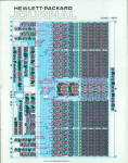
Shown here is the 2240A's control card, which includes 22
SOS components. The 16-bit MC2 microprocessor is used,
along with 12K bytes of read-only memory (ROM), 2K bytes of
random-access read-write memory (RAM), and the PHI
processor/HP-IB interface. The memory cycle time is 100
nanoseconds, compatible with the cycle time of the micro
processor, and the I/O handshake lines of the PHI chip couple
PHI: HP-IB Interface
• Complete HP-IB (IEEE 488-1975, ANSI MC 1.1) interface to
8-bit or 16-bit microprocessor
• Data rate to 1 Mbyte per second
• DMA transfer capability
• Compatible with CMOS or TTL
• 350 mW power consumption
• 9000 transistors in 30 mm2.
Reference
1 B E Forbes. "Silicon-on-Sapphire Technology Produces High-Speed Single-Chip
Processor," Hewlett-Packard Journal, April 1977
'CMOS -complementary metal-oxide-semiconductor.
rotates. The result contains a condition code and the
requested measurements.
Since the entire request is copied into a buffer
within the 2240A, the commands can be executed at a
speed commensurate with the application. This is
generally much faster than would be possible if the
computer had to interact on a command-by-command
basis.
The structure of the language is compatible with
the communications mechanisms available in most
computer programming languages. Simple read,
write, and print statements are used to transfer re
quests and results between the computer and the
2240A. Sending a request to a 2240A is no different
from printing the same message on a line printer. No
special subroutines, I/O routines, or drivers are
needed. Fig. 5 shows programs in three different lan
guages for two different computers performing the
same measurement operations.
Keeping up with the Real World
"Real time" for a computer system can be defined
in many ways, but in the measurement and control
field, its meaning is clear: the computer system must
keep up with the physical motion and timing of the
equipment being tested or measured or controlled.
The timing constraints of a real-time application are
usually very easy to describe. Typically, certain mea
surements must be made at specific intervals or con
trols must be actuated within a certain period follow
ing a triggering signal. It can be complicated, how
ever, to determine whether a computer can keep up
with the prescribed rates. This depends upon the
efficiency of the computer's operating system and on
competition from other programs, as well as on the
raw speed of the processor. With several difficult-topredict variables involved, less-than-convincing
benchmarks must often be used.
The measurement and control processor solves this
© Copr. 1949-1998 Hewlett-Packard Co.
problem for many applications by allowing the cus
tomer to partition a problem into a computational part
and a real-time part. Any computer that meets the
computational needs may be used. The 2240A han
dles the real-time part and makes measurements and
actuates controls as necessary. The 2240A is op
timized for this job, and its capabilities are
straightforward and predictable. In analyzing a typi
cal application, a request can be composed using the
measurement and control language, and its timing
can be determined by adding the times listed in the
manual for each command. Usually this makes it ob
vious whether the 2240A will work or not. Fig. 6
presents an example where the 2240A's timing meets
the requirements of the application. Note that there is
no mention here of the type of computer, its perfor
mance, or the speed of the communication link con
necting it to the 2240A. These factors are not relevant
to the basic will-work/won't-work decision. This is
characteristic of many product-testing and data ac
quisition applications.
In other situations, the computer is in the loop. In
other words, the computer is required to perform
computations on an ongoing basis. This is charac
teristic of closed-loop control applications. Fig. 7 de
scribes a laboratory experiment automated by the
2240A. It shows the 2240A repeatedly taking mea
surements and updating control positions. The
2240A keeps track of the time and starts each new
scan. In this case, the performance of the computer is
important, but only in that it must not use more than
40.2 milliseconds to compute new control values.
The exact time used in computation is not important.
Decoupling computation from measurement and
control timing constraints, as illustrated by these
examples, is a major contribution of the 2240A Mea
surement and Control Processor.
FORTRAN IV (HP System 1000)
DIMENSION VOLTS (40)
WRITE (16,100)
100 FORMAT ("WT,4,1,1 1,1,0!")
READ (16,*)CODE,(VOLTS(I),I = 1,40)
BASIC (HP System 1000)
10 DIM V (40)
20 PRINT #16;"BK,1;WT,4,1,1;AI,2,1,40;DO,3,1,1,0!"
30 READ #16
40 FOR 1 = 1 TO 40
50 READ #16
60 NEXT I
HPL (HP 9825A Desktop Computer)
0: dim V[40]
1: wrt 701,"WT,4,1,1;AI,2,1,40;DO,3,1,1,Or
2: red 701, C
3: for 1 = 1 to 40
4: red 701, V[l]
5: next I
Fig. 5. Requests and results are programmed using the stan
dard read, write, and print statements of most computer lan
guages. Here are programs in three different languages for
two different computers that cause the same measurement
operations to occur.
Simplified Maintenance and Support
Any real measurement and control application
must be maintained and supported after initial de
velopment and checkout. This includes upgrading
hardware and software to incorporate new features as
well as troubleshooting failed components. Distribut
ing intelligence to the 2240A helps in both of these
areas.
Separating timing from computation makes
2240A-based real-time applications less sensitive to
changes in computer performance. A different com
puter may be installed at some future date without
affecting the timing of a critical control loop. Simi-
Application:
Tires are graded by measuring
out-of-round forces as they are ro
tated at 200 RPM (300 ms per rev
olution). The tire circumference is
divided into 20 sectors with 10 volt
age measurements needed per
sector.
Request
RP.20 ; WT,3,2,1; AI,2,1,10
t,-Gather Readings from 10 Sensors
uWait for Next Sector to Rotate Past
L Repeat for 20 Sectors
Timing:
|-« — 0.55 ms— H-« - 10.0 ms - H
R P
W T
A l
N X
20 Sectors x 10 ms = 200 ms
© Copr. 1949-1998 Hewlett-Packard Co.
Fig. 6. By adding the execution
times given in the 2240A manual
for each instruction, a quick de
termination can be made as to
whether or not the 2240A will do
the job, with no need for bench
marking. In this typical applica
tion, the 2240/4 can complete the
required measurements in 200
ms, 100 ms less than the allowable
time.
Measurement and Control Processor
Monitors HP Facility
by Robert B. Grady
At HPs Sunnyvale, California plant, where the 2240A Mea
surement and Control Processor was developed, facility en
gineers had begun to centralize the monitoring and control of
the building's machinery and parameters long before the 2240A
project. Once the project was under way, it was a natural idea to
automate this monitoring and control using a prototype 2240A
and an HP 9825A Desktop Computer as a controller. The appli
cation served as an excellent test site for the 2240A and the
variety of analog and digital function cards developed for this
product line.
Timing Considerations
The facility monitoring system is based on time of day and
elapsed time. The 2240A has both of these real-time clock
capabilities, so no external clocks or time bases are necessary.
The software system is based on easy-to-modify tables. For
example, one table contains measurement time intervals. For
each entry in this table, another table contains a list of mea
surement points to be sampled at the specified interval. The
2240A after TI (time interval interrupt preset) is given after
each measurement sequence to establish the next time interval,
and after the specified time elapses, the 2240A generates an
interrupt to the controller to initiate the acquisition of data. A
simple example of this operation is the on/off digital input points,
which are examined once every 15 seconds, generating listings
of the type shown here:
ON/OFF STflT PTS
NfiME OF PT
CHHN/ON TINE/^ON
fl/C 1
897 6444.1 100
CBP 1
898 8387.3 87
This excerpt shows that chiller boost pump #1 (CBP 1 ) is moni
tored by channel 98 and has been active 87% of the time, or
387.3 minutes.
Concurrently, the time-of-day timer in the 2240A displays the
time of day and determines when facility reports are due (at
0600 and 1800 each day).
Control-Panel Functions
The 2240A is particularly convenient as a simple means of
providing the operator interfaces needed in any system. A
pushbutton switch mounted above the 2240A can be con
nected either to a common interrupt card or to a counter-stepper
card is provide an interrupt to the controller. When the switch is
actuated the operator has the options shown below.
on both the amount of electricity consumed and the highest
peak rate of consumption during some predetermined time
interval. For the HP Sunnyvale facility, this time interval is onehalf hour.
A counter-stepper card counts pulses that represent electri
cal use, and a running record of the latest thirty minutes of
readings is maintained. Whenever a projection of the most re
cent ten minutes exceeds an established limit, an alarm is
generated and personnel have twenty minutes to correct the
temporary excessive use. A typical alarm message is shown
below:
01:35:81 PM
Projected Pk Pur
1355
KflLflRM**
Although not presently done, it would be easy for peak power
consumption to be automatically controlled in graduated steps,
first by a printout showing shut-down priorities, and ultimately by
automatic control of the shut-down and start-up sequences.
When the daily reports are generated, electricity consumption
is summarized as shown here:
ELECTRICITY USE
Projected Month
0144730 Kuh
Peak Hour/Tarset
0000997 Kuh
0881200 Kuh
Solar Heating
The Sunnyvale facility first installed supplementary solar heat
ing in 1973. There are now 448 panels in the system, and these
provide an average of seven million BTUs of energy daily. Two
channels of an analog input card are used to monitor tempera
ture points in the solar heating system. Since flow rates are
known, the number of BTUs generated during the day is easily
determined. Shown here is a typical printout giving the results of
such a computation.
SOLflR HEflTING
Btu's Collected
9519723
Max Btu Rate/Hr
1499042
Rpprox $ Savings
48
The internal timing capability of the 2240A helps deal with the
high 60-Hz noise levels normally present in such an environ
ment. By taking readings precisely timed over one cycle (repeti
tive analog input, 1 7 readings) and averaging them, 60-Hz noise
i s l a r g e l y e l i m i n a t e d . ( c o n t i n u e d )
SUPER INTERRUPT
0
1
2
3
4
5
RESUME
FACILITY RPT
MONITOR fl CHñN
CHflNGE TIME
CHNG TIME TBL
CHG PK PUR LMT
The 2240A can also turn on an alarm to alert personnel to
dangerous conditions. With a 2240A and a controller, a wide
variety of conditions can be examined for alarm generation.
Monitoring Electrical Peak Power
Probably the most significant single parameter in the facility is
peak power. The cost of commercial electrical energy is based
© Copr. 1949-1998 Hewlett-Packard Co.
er, or the function cards since operation began in May, 1977.
An important benefit demonstrated in this application is the
ease with which the system can be upgraded to meet additional
requirements. The table structure of the software is easy to
change and additional measurement and control functions are
easy to add. Since the timing is controlled within the 2240A,
even changing the controller from a HP 9825A to an HP 1000
Computer System will be easy when the additional computing
power is necessary.
Summary
This application is typical of many for which the 2240A pro
vides an excellent solution. It uses both modes of the accurate
internal timer to control when events are to occur, and it uses a
variety of analog and digital capabilities. There are currently 48
digital on/off points, 16 digital interrupt points, three counterstepper points, and 74 analog input points in the system. There
have been no failures in the 2240A, the 2241 A Processor Extend
larly, enhancements to the operating system or new
tasks added to the computer's workload may change
program execution times without disturbing overall
performance.
Robert B. Grady
Bob Grady is remote measure' ment and control project manager
at HP's Data Systems Division.
Most recently he was project man
ager for the HP 2240A hardware.
He has managed development of
the HP ATLAS Compiler, of instru
ment calibration programs, and of
self-test programs for avionics
| systems. A native of Chicago, Il
linois, Bob received his BSEE dei gree from Massachusetts Institute
of Technology in 1965 and his
MSEE degree from Stanford Uniix versity in 1969. He and his wife,
who works for HP as a programmer, have a son and live in Los
Altos, California. Bob plays basketball and Softball in local city
recreation leagues and enjoys mountain vacations — hiking,
camping or skiing. Recently he equipped his home with a
supplementary solar heating system based on the techniques
used at HP in Sunnyvale.
For troubleshooting, the 2240A has built-in selftest and verification procedures. Self-test runs with
out assistance and checks the general health of the
2240A. Verification routines interact with a techni-
Partial Program:
Loop: wrt 701,"WU",S,M,"AI,2,1,5;
AO,4,1 ,1 ",V,"DO,1 ,2,2",W,X,"!"
(The 2240 is sent an HP-MCL request to
wait until (WU) the time in S and M be
fore gathering data and updating con
trols.)
HP2240A
red701,C,T[1],T[2],T[3],A,B
(Condition code and five measure
ments are read when they become
available.)
ell "Update"
(Call a subroutine to save the new data
and compute next time internal and con
trol positions.)
gto "Loop"
(Cycle complete, repeat it.)
Test
Box
Timing:
t+50 ms
t+100 ms
--!-«— 2240 -H-« Computer H-«— 2240— »-H ComputerExecutes Computes/Communicates Executes Computes/Communicates
-«-9.8 ms-»—
-Less than40.2 ms
© Copr. 1949-1998 Hewlett-Packard Co.
Fig. 7. In this laboratory automa
tion application, a mechanism is
being tested at varying tempera
tures using a user-designed test
box. The 2240A Measurement and
Control Processor gathers data at
50-ms intervals and sends it to the
9825A Desktop Computer for pro
cessing. Since the 2240A takes
9.8 ms in this application, the
computer has up to 40.2 ms to
process the data. The exact com
putation time is not important.
cian to locate a failing printed circuit card, or to show
proper operation for initial customer acceptance.
Built-in service tools are a benefit to HP as well as to
the customer. For HP they mean that diagnostic tools
need not be developed and supported for each com
puter that might be used with the 2240A. The user
benefits since the 2240A can be serviced while dis
connected from the computer. Other computer func
tions can continue undisturbed, and the servicing can
be done at the application site, often remote from the
computer.
Acknowledgments
Thanks are due many people on completion of a
product of this scope. Bill Ray, measurement and
control lab manager, refined product objectives and
led us to a timely introduction. Pete Palm, Norm
Galassi, and Ron Carelli provided marketing inputs.
Dick Toepfer provided early project leadership and
established manufacturing capability for the 2240A.
Analog function cards were designed by Vince
Dauciunas and Dick Cook, who also developed the
power supply and breadboard card. Digital functions
were the product of Jim Wrenn, Vince Cavanna, and
Dave Grus. Jim Wrenn, as number one critic of design,
testing methods, and documentation, deserves major
credit for product quality. Brice Clark led the signal
conditioning effort with Dick Van Brunt and Charlie
Martin providing the engineering. Product design
was by Dick Riley. ¿?
References
1. P.D. Dickinson, "Versatile Low-Cost Graphics Terminal
Ray H. Brubaker, Jr.
Native Californian Ray Brubaker
obtained BSE and MSCS degrees
in 1971 from the University of
' California at Los Angeles.
Graduating with three years of sys
tems programming experience at
the UCLA Computer Center, he
spent the next few years at the
Naval Postgraduate School in
Monterey, California as an assis
tant professor of computer sci
ence. He taught a variety of
courses and supervised several
L microprocessor-based research
1 projects. Joining HP in 1974, he
I operating system before joining the
2240A team. As project manager for controllers, Ray contri
buted to management and design of the 2240A's SOS-based
control card and HP-MCL firmware. Church activities, carpen
try, and and flying are a few of Ray's special interests. He and
his wife and their two-year-old daughter also enjoy weekend
outings in the camper they built.
Is Designed for Ease of Use," Hewlett-Packard Journal,
January 1978.
2. L.G. Brunetti, "A New Family of Intelligent Multi-Color
X-Y Plotters," Hewlett-Packard Journal, September 1977.
3. B.E. Forbes, "Silicon-on-Sapphire Technology Produces
High-Speed Single-Chip Processor," Hewlett-Packard
Journal, April 1977.
SPECIFICATIONS
HP 2240A Measurement and Control Processor
MAINFRAME CAPACITY: 4 slots for any mix of function cards listed below; up
to 128 analog/digital I/O channelsHP 2241A EXTENDER: 4 additional slots for function cards; under control of
HP 2240A for a total of 256 analog/digital I/O points.
HP 2240A & HP 2241 A DIMENSIONS: 482 mm W x 223 mm H x 356 mm D
(19 x 8% x 14 in.).
WEIGHT: HP 2240A: 13.8 kg (30.4 Ib) not including function cards.
HP 2241A: 13.1 kg (28.8 Ib) not including function cards.
POWER: 120, 240 Vac; +6%, -28%; 48-66 Hz; 130 watts maximum (including
function cards).
ENVIRONMENTAL: 0= to 55CC 2240A air intake ambient.
SAFETY: UL listed under Process Control Standard 1092, Data Processing
Equipment (UL478), Office Appliances (UL114).
INTERFACE: HP-IB(IEEE Standard 488-1975); needs controller with ability to
handle Abort). HP-IB messages (Data, Require Service, Status Byte, Clear, Abort).
PROGRAMMING INTERFACE: Commands to the 2240A and data returned is
via standard HP-IB messages. Any HP-IB controller that can send and receive
ASCII HP-IB data messages can control the 2240A. Examples are HP 1000,
9825, 9815, and 9830. The HP 2240A receives, interprets, and executes 48
ASCII scanning, (see p. 4 for complete list) for such tasks as scanning,
timing, pacing, and synchronizing with external events.
FUNCTION CARDS (Process/Machine Interfaces)
HP 22900A ANALOG INPUT CARD: 12-bit, ±10V, 20-kHz ADC with 32
single-ended or 16 differential channel input multiplexer. Accuracy with
auto correction for gain and drift, .05% input channel span ±1/2 LSB;
0-55°C.
HP 22901A ANALOG OUTPUT CARD; 4-channel, 10-bit, 0-10V (unipolar) or
-10V to +10V bipolar DAC outputs (5mA), accuracy ±0.1% @ 25'C,
resolution 10mV (unipolar) or 20mV (bipolar).
HP 22901B ANALOG OUTPUT CARD: 4-channel, 12-bit, 0-10V (unipolar),
-10 to 10V (bipolar), or 4-20mA (current) DAC outputs, accuracy
±0.025% (voltage), ±0.1% (current), resolution 2.5mV (unipolar), 5mV (bi
polar), or 5 /¿A (current), Kelvin connections.
HP 22902A DIGITAL INPUT CARD: 32-channel TTL/CMOS compatible input
levels. Voltage or dry contact sense.
HP 22903A COMMON INTERRUPT CARD: 16-channel TTL/CMOS level com
patible (individual channels maskable and transition direction
programmable). Voltage or dry contact sense.
HP 22904A DIGITAL OUTPUT CARD: 32-channel, open-collector NPN switch
outputs, levels or pulses.
HP 22905A COUNTER/STEPPER CARD: 4 channels individually configurable
for frequency or period measurement, event counting or stepper out
put. TTL compatible.
SIGNAL CONDITIONING CARDS (mount in 22920A tray and Condition Sig
nals — in and out — for Function Cards).
HP 2291 jumper- LOW-LEVEL ANALOG INPUT: 16 low-level differential inputs, jumperselectable gains ±20mV, ±50mV, ±100mV, ±0.5V, ±10V; pads
for filters, current loop and open thermocouple detection resis
tors. input amplifier-per-channel outputs connect to 16 single-ended input
channels of HP 22900A.
HP 22912A RELAY OUTPUT: 16 Form-C (SPOT) relays, 2A, 125Vac/dc,
60V A.
HP 22913A ISOLATED DIGITAL INPUT: 16 optically isolated and fused chan
nels, user-selected ranges 5-120 Vdc, 16-230 Vac for each channel.
HP 22914A GENERAL PURPOSE BREADBOARD: Layout optimized for 16
analog or digital signal conditioning circuits.
HP 22920A SIGNAL CONDITIONING TRAY (1% in. H x 19 in. W x 14 in. D): in
cluding 2 Buchanon 28-screw termination connectors for field wiring.
PRICES IN U.S.A.: HP 2240A Measurement and Control Processor, $2750.
Installation/Function Test requires HP 22909A Text Fixture ($440). HP 2241A
Extender, $1500. Bench Top Covers for HP 2240A/HP 2241A, $60. Function
Cards: 22903A, $1600. 22901A, $900. 22901B, $1200. 22902A, $310. 22903A,
$450. 22904A, $480. 22905A, $800. Signal Conditioning Cards: 2291 5A,
$1250. 22912A, $290. 22913A, $430. 22914A, $130. 22920A, $165.
MANUFACTURING DIVISION: DATA SYSTEMS DIVISION
11000 Wolfe Road
Cupertino, California 95014 U.S.A.
© Copr. 1949-1998 Hewlett-Packard Co.
Firmware Intelligence for Measurement
and Control Processing
The HP 2240A demonstrates how HP-IB communications
are maturing as instruments gain in sophistication.
by Donald E. Klaiss
temporary data storage, the PHI processor/HP-IB in
terface chip, and interface circuits to manage the
measurement and control function cards.
The 2240A communicates with a computer using
request and result messages as described in the pre
ceding article. Firmware directs the MC2 to receive an
incoming request from the PHI HP-IB interface chip
and store it in the request/result buffer, which is part
of the control card RAM. A request contains one or
more commands, such as Al for analog input or DO for
digital output. After receipt of a complete request, the
2240A interprets each of the commands in sequence
and conveys the appropriate control information to
the measurement and control cards. As the request is
executed, the microprocessor builds up a result con
taining a condition code and any desired measure
ment data. Measured data from external signals is
scaled and formatted before it is stored in the result
buffer. Analog input readings are corrected for temp-
MICROPROCESSOR INTELLIGENCE makes it
possible to design a new level of capability
into today's instruments, so that more of the pro
cessing responsibility can be transferred from system
computers to the instrumentation. This new breed of
peripherals is more powerful, more broadly com
patible, and easier to use than any previously avail
able equipment.1
Microprocessors execute programs stored in ROM
(read-only memory). These programs, or firmware,
provide the "personality" of any given micropro
cessor-based product.
In the HP 2240A Measurement and Control Proces
sor, all activity is controlled by HP's new MC2 SOS
(silicon-on-sapphire) microprocessor.2 The micro
processor resides on the 2240A control card (see Fig.
1), and executes firmware programs stored in 12K
bytes of on-board ROM. The control card also con
tains 2K bytes of RAM (random-access-memory) for
2240A
Backplane
HP-IB
MC2
Microprocessor
Timing
Reference
Timing Signals
Commands and Controls
To
Computer { HP
Controller
Processor Bus
Function
Card
Interface
Data
Interrupts
4K
2K
ROMs (6K x 16 Bits)
RAM (1K x 16 Bits)
Firmware for
• HP-IB Communications
• Command Interpretation
• Backplane Control
• Data Conversion and Correction
• Interrupt and Status Handling
' Interval Timer
i Elapsed Time
Configuration Tables
Correction Tables
Status Buffers
Request/Result Buffer
• Verification and Self Test
200 Words
800 Words
Fig. Processor . the the control card in the HP 2240 A Measurement and Control Processor are the MC2
microprocessor, the PHI HP-IB interface chip, 2K bytes of random-access memory (RAM), and
12K bytes of read-only memory (ROM). All of these devices are products of HP's silicon-onsapphire (SOS) technology.
10
© Copr. 1949-1998 Hewlett-Packard Co.
2240A
Measurement
and Control
Function
Cards
Digital Input
Digital Output
Common Interrupt
Computer T HP-IB
Analog Input
Analog Output
Counter Input
Stepper Output
Fig. the performs 2240A receives requests from the system computer over the HP-IB, then performs
the requested tasks, and returns the results to the computer. Five 2240A baiters are accessible to
the computer. The request/result buffers handle normal communications and the other three
buffers contain status information.
diagram form.
The primary responsibility of the executive is to
execute requests and prepare results. It also performs
automatic calibration of ADC (analog-to-digital con
verter) channels when signaled by a temperature
change.
Fig. 4 delves more deeply into the executive state in
which a request is executed. After initializing the
condition code in the result buffer to zero, indicating
no errors, the executive begins interpreting and
executing commands in sequence. If the syntax of the
current command is found to be correct, a command
handler routine is called to execute that command.
The normal exit from the request processor occurs
when the request terminator character, !, is encoun
tered. The result now contains the condition code and
result data. Any error, such as an unrecognized com
mand or recognition of a malfunctioning card, stops
the request, changes the condition code to 1, and
discards any data in the result.
In this fashion, a request always produces a result
that is made available to the computer. If an error has
occurred, the result contains only the condition code.
The executive does no HP-IB communication itself;
instead, it executes requests placed in the 2240A's
buffer by the inbound message processor. Similarly,
the result is accumulated in the buffer during the
execution of a request and is transmitted by the out
bound message processor. This interaction is shown
graphically in Fig. 5.
The inbound message processor is responsible for
the transfer of messages, one character at a time, from
erature drift (see box, page 13). When the entire re
quest has been executed, the result is made available
for transmission to the computer. A model of this
interaction is shown in Fig. 2.
Approximately 1600 bytes of RAM are available for
request and result buffering. In addition to the
request/result buffer, the 2240A continuously main
tains three special status buffers that contain informa
tion about the state of the processor. This includes
any interrupts that have occurred, the number of the
command currently being executed, and detailed in
formation about errors. The status buffers may be read
at any time, even interrupting the transmission of a
request or a result, without loss of data. Status is read
by using HP-IB secondary addresses 1, 2, and 3, or by
sending special character sequences to the 2240A.
HP-IB secondary addressing provides efficient trans
fer of any of the three status buffers with a single read
statement. The special character sequences are pro
vided for computers that do not support the HP-IB
secondary addressing mode.
Firmware Architecture
The 2240A firmware is organized as three inde
pendent but cooperating tasks: an executive, an in
bound message processor (IMP), and an outbound
message processor (OMP). This multi-tasking ar
chitecture provides real-time advantages. For exam
ple, the message processors can handle requests for
status information immediately, even though the
executive is busy performing a measurement or con
trol sequence. Fig. 3 presents the three tasks in state
11
© Copr. 1949-1998 Hewlett-Packard Co.
IMP: Inbound Message Processor
EXEC: Request/Result Executive
OMP: Outbound Message Processor
PHI Can't
Accept
More
Request
Character:
EXEC Free
Request
Character
EXEC
Busy
with
Prior
Request
Activate
IMP
to Receive
Request
Request
Processor:
Execute
Commands
and Build
Result
New
Request
Received:
Discard
Result
No New
Request
Received
Activate
OMP
to Transmit
Result
Exclaimation
Point Received:
End of Request
Message Transmission Complete
or PHI Can't Accept More Characters
Fig. ROM. organized 2240 A is controlled by firmware programs stored in ROM. The firmware is organized
as the three cooperating tasks shown here. The IMP is the highest-priority task and the EXEC is
the lowest. A higher-priority task can preempt one of lower priority. Normal request/result flow is
shown by the heavy lines.
one is still being executed, the inbound message pro
cessor suspends itself until the executive indicates
the current request has been completely executed.
The outbound message processor transmits result
or status messages to the computer over the HP-IB. It
does this by placing eight characters at a time into a
first-in first-out (FIFO) buffer on the PHI HP-IB inter
face chip. The OMP is also interrupt driven in that it
suspends itself when the PHI cannot accept more
bytes. When the PHI has transmitted the eight bytes, it
interrupts the microprocessor to indicate that it has
room for eight more. When the computer is accepting
characters quickly, as with direct memory access,
suspensions do not occur and the MC2/PHI combina
tion sustains a data rate greater than 200,000 charac
ters per second.
Occasionally the transfer of a result by the out
bound message processor is preempted by a status
transfer. For example, the main program in the com-
the HP-IB into the 2240A. Normally these characters
are part of a request and are stored in the request
buffer for the executive. To conserve buffer space,
redundant blanks in the character stream are re
moved. When the request terminator character, !, is
received, the inbound message processor signals to
the executive that a complete request is available. The
IMP must also watch for special characters or secon
dary addresses indicating status information is
needed, and signal the outbound message processor
to transmit the appropriate data.
The inbound message processor is normally inter
rupt driven and is activated whenever the PHI chip
indicates that bytes are available on the HP-IB. When
no more characters are immediately available, the
IMP suspends itself until an interrupt indicates that at
least one character has arrived. When characters are
arriving but there is no place to put them, such as
when a program sends a new request while an earlier
12
© Copr. 1949-1998 Hewlett-Packard Co.
Analog Input Card Calibration
by Vincent J. Dauciunas
The microprocessor then stores this value. Next, switches
S2 and S4 are opened and S1 is closed, connecting the inputs
back to A1 .
All succeeding readings from the 22900A are now processed
by the microprocessor through the formula:
Analog inputs to the 2240A are handled by the 22900A multi
plexed analog-to-digital converter card. The 22900A provides
for up to 32 single-ended or 16 differential high-level analog
inputs, with a conversion rate of up to 20 kHz.
One of the important features of the 22900A is the ability to
convert either a grounded input or a precision reference volt
age. Another is the ability to sense temperature changes near
critical components. Together these features allow the micro
processor to compensate analog readings fortemperature drift.
The basic technique can be seen by referring to Fig. 1 . A differential-to-single-ended converter, a sample-and-hold amplifier,
and a 12-bit successive approximation analog-to-digital con
verter form the heart of the conversion circuitry.
Each of the blocks is subject to errors as a result of offset volt
age and gain changes as a function of time and temperature.
Since the blocks are cascaded, the errors of a preceding block
are modified by each succeeding block. To achieve high accu
racy over the full operating temperature range, it is necessary
either to use costly, stable, precision components, or to perform
periodic calibrations. The 2240A takes the latter approach.
To calibrate the 22900A card, the following sequence is
performed. Switch S1 is opened, and switches S3 and S4 are
closed. This applies ground to the inputs of A1, and the resultant
output, which is the total offset, is
Vcorrect = G(Vreading ~ Eo)
which produces an output that is corrected for gain and offset
errors. The microprocessor also checks that the values of
G and E0 are within acceptable bounds. If they are not, an
error message is generated, indicating a possible ADC card
fault.
The 2240A allows for two modes of autocalibration: usercontrolled or automatic. User-controlled autocalibration is
initiated by the AC command, and is executed immediately.
Automatic calibration is performed only when the on-card
temperature, as determined by a temperature sensor, changes
by a predetermined amount. The ADC card then generates an
interrupt, and the microprocessor performs an autocalibration
cycle. All succeeding readings from the card are corrected by the
newly established correction factors until a user-requested or
interrupt-generated calibration cycle results in a new set of
correction factors.
The ability to switch in the ground or reference voltage
through the use of several other low-level 2240A commands
also yields a useful diagnostic tool in tracking down possible
faults should there be a suspected problem with a 22900A card.
E0=((E01G1+E02)G2+E03)G3.
This value is stored by the microprocessor. Next, S3 is opened
and switch S2 is closed. This applies VRef to the inputs of A1,
and the resultant output is:
V0 = (((VRe) + EoOG, + E02)G2 + E03)G3
"A similar calibration principle is used in the 3455A Digital Voltmeter (Hewlett-Packard
Journal, February 1977).
V0 = GAGaVfte, + G,G2G3E^ + G2G3Eo2 + G3Eo3
A gain correction factor is computed by
V' RR e l
G =
Vn-En
V : R,
G1G2G3VRef
G1G2G3E01
+
G2G3Eo2
+
G3Eo3
~
G1G2G3Eo1
~
G2G3Eo2
~
G3Eo3
1
G1G2G3
Differential-toSingle Ended Converter
Sample and Hold
ADC
Digital
Output
EO, = Device Offset Voltage
G¡ = Device Gain
Temperature
Sensor
V
Fig. analog-to-digital . converter block diagram of the HP 22900 A multiplexed analog-to-digital converter card.
The card tempera convert a grounded input or a precision reference voltage and can sense tempera
ture changes near critical components. These features allow the microprocessor to compensate
readings for temperature drift.
13
© Copr. 1949-1998 Hewlett-Packard Co.
Calibration
Interrupt
address. The arrival of this address immediately in
terlocks the PHI chip's outbound FIFO buffer so that
none of the result characters will be accidently read
by the interrupt routine. This gives the micro
processor time to gather the status information and
place it in the outbound FIFO buffer, after saving any
result data still in the FIFO buffer. After all the status
information is accepted by the computer, the out
bound processor resumes result transmission, and the
main program continues, unaware of the entire trans
action. If request execution is of higher priority than
status response, the 2240A can be instructed not to
respond to status reads until after execution of the
request has been completed.
Execute Request,
Build Result
^ ^ ^ M
Initialize
C o n d i t i1
on Code = 0
Parse Next Command
Request
Terminator (!)
Found .
Yes Request Finished
Verification and Self Test
[No
A major concern of equipment users is how to ver
ify that the equipment is functioning properly. In the
2240A this concern is addressed by two types of
built-in service tools: self-test and function card ver
ification.
The self-test runs whenever the 2240A is powered
up, or upon command from the computer. It checks
for proper operation of the microprocessor, ROM,
RAM, PHI chip, interrupts, and function card inter
face circuits. In the ROM test, for example, MC2 uses
the contents of each ROM cell to compute a cyclic
redundancy check code, which is then compared to
the proper code stored on each page of memory. This
test verifies that the contents of each ROM is correct
and that the chips are loaded in the proper socket. The
entire self-test sequence executes in less than three
seconds.
The function card verification test is run to verify
proper operation of the measurement and control
cards and to diagnose any problems. To run these
tests, the 2240A is switched off-line and a test fixture
is connected to the rear of the instrument. This fixture
simulates input signals and displays output signals.
The test sequence is initiated by pressing a button on
the front of the control card. The verification tests for
the analog cards also provide a procedure for calibrat
ing the cards. The technician can interact with the
2240A through switches and light-emitting-diode
indicators on the test fixture and the control card. The
flow chart of the analog-to-digital converter test is
shown in Fig. 6.
Check Command
and Parameter Validity
Execute Command:
Call Command Handler
Discard Result
Set Condition
Code = 1
Mark End of
Result with crit
Return to EXEC
Fig. 4. Request processing flow chart. Requests are pro
cessed by executing a series of commands in sequence.
Command handler routines are called during request process
ing to execute various types of commands.
Assuring Compatibility
putei might be reading the result from a scan of sev
eral sensors when the 2240A interrupts because a
limit switch has tripped. An interrupt routine in the
computer must then decide what caused the interrupt
and whether it requires immediate corrective action.
The necessary information is in the 2240A interrupt
status buffer and is requested by sending the 2240A a
status command in the form of an HP-IB secondary
The design objectives for the 2240A included direct
plug-in compatibility with any HP-IB controller and
language. A number of design features make this pos
sible.
Messages, not Characters. 2240A communication is
implemented and documented in terms of a few
high-level "metamessages". Interaction at this level
assures that subtle differences in command and data
14
© Copr. 1949-1998 Hewlett-Packard Co.
HP-IB
HP-IB
Request: Wait until Time = 30 Seconds, then
Turn on Digital Output Slot 3, Channel
12. Wait for Trigger from Input at Slot 2,
Channel 1; then Take Analog Input
Measurements from Slot 1, Channels 1
through 4 and Read the Time Elapsed.
Result: Condition Code = 0 (No Errors),
Channel 1 = 100 mV, Channel 2 =
200 mV, Channel 3 = 300 mV,
Channel 4 = 400 mV, Time = 50
Seconds, 26 Milliseconds.
Fig. 5. Message flow among the
three 2240A firmware tasks.
sequences will not preclude using the 2240A with a
given controller. HP has begun describing the use and
the capabilities of its computers and instruments in
terms of messages transferred. This provides a com
mon ground for relating any instrument to any com
puter. The objective is to allow the use of N instru
ments with M computers without writing N times M
user's manuals. The 2240A uses the following HP-IB
messages: data, clear, require service, status bit, and
abort.
Computable Parameters. Careful consideration to
parameter format assures straightforward program
ming. Consider the request: AB,3,4,i,-ioo!. This analog
bipolar output command will cause -100 millivolts
to be produced at the connection to channel 4 of the
digital-to-analog converter in slot 3. This seems sim
ple enough, but more often than not some or all
parameters are computed and come from program
variables instead of ASCII constants. This usually
results in a character sequence such as:
and trailing blanks. Spaces, commas, and semicolons
may be freely used as delimiters, and upper or lower
case letters are acceptable for commands. While de
limiters make a request more readable, they are re
quired only between adjacent numeric fields.
Explicit Request Terminators. The exclamation point
(!) was chosen as the request terminator to avoid a
programming complication. While most computers
send the ASCII carriage return and line feed (cr If)
characters at the end of a message, suggesting their
use as a message terminator, some do not. Still others
send cr If in the middle of messages, after every few
numeric fields. The2240A ignores cr If sequences and
continues to accept request characters until ! is re
ceived. This convention frees the programmer from
concern with the cr If conventions of the computer. It
is particularly convenient to know that cr If is ignored
when multiple write statements are used to send ar
rays of data within a request.
Universal Result Format. The result carries mea
surement, timing and error information to the com
puter. All 2240A quantities are expressed as integers
and transmitted in standard free-field ASCII for
mat. This format is acceptable to all current HP com
puters that support the HP-IB. The 2240A will pad
the result with zeros and commas to the extent re
quired to satisfy a read statement that asks for too
much data. This normally occurs after an error termi
nates a request but the program expects measure
ments in the result. Padding avoids a potential
"hang-up" situation.
Respect for Buffer Size. While the 2240A can produce
a result nearly 1600 characters long, some languages
restrict the number of characters that may be trans
ferred by a single read statement. This limitation
AB, 3 3.99999 1, -100.37 !
This has exactly the same effect as the previous re
quest. The 2240A rounds the 3.99999 to 4, the
-100.37 to -100, and is tolerant of the extra delimit
ers. Difficult-to-compute formats, such as 100— for
negative voltages and 3.4 for slot 3 channel 4, have
been avoided.
Flexible Request Syntax. Some peripherals require
that the programmer precisely control the data format
of a WRITE or other output statement. The 2240A re
lieves the programmer of these concerns by accepting
anything that a person can read unambiguously.
Commands and data may be surrounded by leading
15
© Copr. 1949-1998 Hewlett-Packard Co.
PHI, the HP-IB Interface Chip
by John W. Figueroa
In the 2240A Measurement and Control Processor, the inter
face between the MC2 microprocessor and the HP-IB is im
plemented by a single LSI CMOS/SOS chip called PHI (pro
cessor to HP-IB interface). Although well suited for its HP2240A
application, it has more general capabilities, including the entire
logic interface of IEEE standard 488-1975.
How the HP-IB standard became the PHI chip makes an
interesting story. Since it had been an early goal of HP's Data
Systems Division to standardize peripheral interfaces, the divi
sion in 1972 contributed modifications to the proposed HP-IB
standard that made it better suited to computer systems. Unfor
tunately, this introduced further complexity and made it likely
that multiple independent implementations of the HP-IB would
result in system -level problems.
The talker/listener functions of the HP-IB, needed by
peripherals and instruments alike, could be readily im
plemented with discrete 1C logic. However, the full controller
function and processor interface needed by the computer I/O
channel added considerable logic to the design. At that time,
only small and medium-scale integrated circuits were available
to implement the added logic. The resulting increase in size of
the interface, a higher manufacturing cost, and longer and more
costly development were not acceptable in the long run.
The solution to these problems was obviously an LSI chip, but
the technology for a large, random logic design fast enough for
tape drives and discs was not to be available until years later
with the emergence of HP's CMOS/SOS technology. With the
proper technology it became possible to produce the PHI chip.
PHI is destined to be used in the design of a new generation of
microprocessor-driven controllers, peripherals, and instru
ments.
16-bit CMOS/SOS microprocessor but also operates with mini
mal additional logic with most 8-to-1 6-bit microprocessors. The
HP-IB side is standard and will not be described here.
Maskable processor interrupts and DMA handshake are im
plemented, allowing PHI to operate in parallel with and inde
pendently of the microprocessor. These features enhance the
total pro performance, effectively freeing the pro
cessor from the details of the HP-IB I/O.
There are nine distinct bits in the first-level priority interrupt
register. A tenth bit is the logical OR of the other nine and con
nects to the processor interrupt line. All ten bits are individually
maskable. If appropriate, they are individually clearable by the
processor.
The outbound FIFO buffer in a controller PHI allows queueing
of HP-IB commands and macrocommands that direct the trans
fer of data sent by other talkers over the HP-IB at the full onemegabyte rate. The macros allow synchronous control by virtue
of the controller PHI's participating in every handshake. The
three macrocommands provided are an uncounted transfer
terminated by the HP-IB EOI bit, a counted transfer terminated by
count=0 or by EOI, and a counted transfer terminated as above
or by a line feed. Counted transfers larger than 256 bytes are
handled by automatic chaining of macrocommands from the
outbound FIFO buffer.
When the outbound FIFO buffer in a controller PHI is empty,
the PHI saves time by automatically conducting a continuous
parallel poll operation. This poll is terminated as soon as the
processor writes a word into the outbound FIFO buffer.
The parallel poll responses are maskable and normalized for
high/low polarity for each bit. The resulting eight bits are avail
able to the processor as a second priority level of interrupts. The
logical OR of all the masked responses constitutes a first-level
priority interrupt.
A programmable two-byte identify capability is provided to
allow a computer acting as an HP-IB controller to find out via the
HP-IB what peripherals or instruments are currently connected
to its HP-IB I/O system.
The remaining programmable PHI registers handle the HP-IB
address and miscellaneous control and status bits for normal
and diagnostic operation. (Continued on next page.)
PHI Architecture
The PHI chip provides a microprocessor I/O interface or
ganized around seven registers for interrupt, control, and
status, as well as two independent first-in first out (FIFO) data
buffers. Fig. 1 is the block diagram of the PHI chip.
The processor bus operates with either 5-volt TTL or 12-volt
MOS microprocessors. It is ideally suited for use with the HP
'An LSI complementary chip is a large-scale integrated circuit chip made by the complementary
metal-oxide-semiconductor silicon-on-sapphire process.
Microprocessor Bus
Parallel Poll
Normalize/2nd ID
Interface
Command •
Decoder • Status Byte
Parallel Poll
Response
First
Identify
Byte
T
HP-IB
Fig. entire of diagram of the PHI chip. The chip implements the entire logic interface of IEEE
488-1975.
16
© Copr. 1949-1998 Hewlett-Packard Co.
Second
Identify
Byte
Diagnostic Capabilities
A programmable off-line state as well as FIFO buffer
wraparound (from outbound to inbound) are part of the exten
sive diagnostic capabilities provided. Most registers can be
written to and read from to assist in firmware debugging. The
off-line test can be done totally by software without disconnect
ing the PHI from a working HP-IB system. The 2240A uses this
feature in its self test.
Unlike the HP-IB handshake, the processor handshake will
not freeze the processor bus if the data transfer cannot be
executed. In lieu of waiting, a FIFO operation completes without
a real data transfer and is followed by an interrupt. This allows
efficient firmware debugging and error recovery.
Separate parity generator and checker logic is provided for
HP-IB commands. A parity error generates a maskable interrupt
but allows execution of the HP-IB command.
For further parity error control, a programmable control bit
allows freezing of the HP-IB handshake and reading of the
HP-IB DIO lines, but does not execute the questionable com
mand. Normal operation goes on when the transient disap
pears, when the controller times out (not a PHI function), or when
the receiving PHI is reset.
Yes
Read Reference 16 Times
Correct and Average Readings
Display Error
Adjust Reference
John W. Figueroa
John Figueroa joined HP in 1969
with a BSEE degree from the Uni
versity of Florida. After writing
much automatic test software and
managing a programming group,
John transferred in 1972 to HP's
Data Systems Division to work on
the new computers being de
veloped. An early advocate of the
HP-IB for computer I/O, he be
came a group manager for HP
3000 hardware and then for HP
2000 Systems. Since 1975, John
has been doing R&D on the MC2
and PHI LSI chips while pursuing
his MSEE at Stanford University (he received it last month). He is
married, has two sons, and enjoys chess, skiing, science fiction,
and driving his 1961 Corvette.
Differential
Single-Ended
Scan 16 Channels and
Check that All Are within
Specified Limits
Scan First 16 Channels and
Check that All Are within
Specified Limits
Scan and Check Second
16 Channels
normally arises because of a small buffer in the
computer's memory, often only 80 to 144 characters
long. Reading a long message into a short buffer usu
ally results in loss of most of the message. The 2240A
compensates for this by breaking a long result into
several smaller messages when necessary. Two com
mands are provided to control this blocking feature.
Transparent Multiplexing of the HP-IB. The normal
data flow between a computer program and an in
strument may be broken by an interrupt that signals
an unusual event and invokes a special interrupt ser
vice program. Such a program can immediately inter
rogate the status buffers of the 2240A for various
information, such as the cause of the interrupt and the
command currently being executed. The interrupt
program can use HP-IB secondary addressing to read
from the status buffers. When the main program con
tinues, it will not see any effect of the interruption,
even if it occurred in the middle of a request or result
, Yes
Continue
Illuminate Error
Indicator to Inform
Operator of Problem
Fig. built Self-test and function card verification tests are built
into the 2240 A firmware. This is the flow chart of the verification
test of the analog-to-digital converter input card.
transmission.
Alternative for Secondary Addressing. The 2240A is
accessed via its primary HP-IB address for transmit
ting requests and reading results. A secondary ad
dress is sent along with the primary address for read
ing status information. The secondary address affords
an unambiguous selection of a status buffer and trans
fer of its contents with a single read statement. Since
17
© Copr. 1949-1998 Hewlett-Packard Co.
many hours on software testing.
Special thanks go to Fred Johnstone as author of the
excellent 2240A user's manual. S
References
1. R.H. Brubaker, Jr. andD.E. Klaiss, "Microprocessor Intel
ligence in Instrumentation Simplifies Computer Software,"
Proceedings of the Instrument Society of America Confer
ence, Niagara Falls, N.Y., October 17-20, 1977.
2. B. Forbes, 'Silicon-on-Sapphire Technology Produces
High-Speed Single-Chip Processor," Hewlett-Packard
Journal, April 1977.
Fig. 7. HP Model 2240 A Measurement and Control Processor.
Vincent J. Dauciunas
Vince Dauciunas received his
BSEE degree from the University
of Notre Dame in 1972 and his
MSEE from the University of
California at Berkeley in 1974. Dur
ing his student years, he worked
on ground receivers for deepspace tracking and served as a
teaching assistant. With HP since
1974, he's the designer of the
22900A ADC card for the 2240A
j Measurement and Control Prof cessor. Vince was born in Culver
< City, California. He's married, lives
in Santa Clara, California, and enjoys radio-controlled sailplanes, volleyball, and photography,
He's a member of IEEE.
some computers or languages may not support sec
ondary addressing, a scheme was devised for them to
simulate secondary addresses. The following se
quence, written in HP BASIC, simulates a read from
secondary address 2 , the 2240A's extended status buf
fer:
PRINT #12; "$T2" Send special command
for status reading
READ #12; A, B, C, D Read status information
The $T... sequence is treated as a special case by the
2240A. It means secondary ($) talker (T) number two
(2). While not currently used, $L... could simulate a
secondary listener selecting the target of a data trans
fer.
Block-Oriented Transfers. Computers operate most
efficiently when I/O operations deal with blocks of
data, usually via direct memory access channels, in
stead of programmatically with individual bytes. In
telligent peripherals can store and process large
amounts of data and are therefore compatible with
block transfers. The 2240A request/result protocol is
designed to encourage block transfers. The 2240A can
receive a request at 70,000 bytes per second and
transmit a result at 200,000 bytes per second.
Donald E. Klaiss
Don Klaiss joined HP's Microwave
¡ Systems Lab in 1973 after receiv
ing a BSEE degree from Rutgers
University in New Jersey. He re
ceived his MSEE degree from
Stanford University in 1975 and is
currently pursuing an MBA at
Santa Clara University. He has
been involved in the design of
several HP products including the
8542B Automatic Network Ana
lyzer and the ARS-400 automatic
spectrum analysis and receiver
system. He had major respon
sibility for HP-MCL firmware
design for the 2240A Measurement and Control Processor. Don
is now responsible for measurement and control firmware de
velopment at HP's Data Systems Division. He has published
technical articles and is a member of the IEEE Computer Soci
ety. Don is single, lives in Mountain View, and enjoys tennis,
volleyball, camping, music, theater, and playing piano and
guitar.
Acknowledgments
The author wishes to acknowledge the many efforts
of the other members of the controller team. Ray
Brubaker made major contributions to the control
card hardware as well as firmware architecture and
design. As primary backplane architect, John Wiese
designed the function card interface hardware on the
control card, as well as verification and self-test
firmware. Vic Hardy designed the verification test
fixture and verification firmware. Terry Leuthner im
plemented the ADC calibration firmware and spent
18
© Copr. 1949-1998 Hewlett-Packard Co.
An Easy-to-Use Data Capture Terminal for
Industrial Operations
Designed for collecting data at remote points within a
manufacturing operation, this compact terminal is operated
easily by those unfamiliar with computer operations. It
ca n a l s o s e r v e as a l i nk bet ween a co mp u te r a n d d ista n t
HP-IB-controlled instruments.
by Jacques A. Ripert, Daniel C. Berthier, and Michel E. Bernard
• It is often desirable to collect data such as tempera
tures, pressures, and voltages automatically from
test stations distributed throughout the plant. In
addition, it may be desirable to control the test
instruments from a central location.
These considerations influenced the design of the
HP Model 3070B Terminal (Fig. 1) and the data col
lection system with which it works.
DATA COLLECTION OPERATIONS are found in
an extremely wide variety of situations — manu
facturing, inventory control, point of sale, hospitals,
to name a few.
The characteristics of these different applications
are such that no one terminal satisfies the needs of all.
Therefore, when the design of new terminals for data
collection was undertaken at HP, strict attention was
paid to fulfilling the needs of the industrial environ
ment, the intended area of application for these ter
minals.
The principal characteristics of the industrial envi
ronment are as follows.
• A great variety of tasks are performed simultane
ously in different parts of the factory. In general,
decisions or actions related to these tasks are based
on the latest information received, so it is highly
desirable to collect data on a real-time basis.
• Users of the terminals are not data-processing
specialists. They must perceive the terminals as a
help and not as a nuisance that complicates their
work.
• Necessary information is generated wherever the
work is done, so the cost of cabling and the ease of
installation could become significant factors in the
total investment in a data-collection system.
• Factory needs change, so a terminal should be cap
able of being relocated easily without major
changes in the cabling. Hence, ease of connection
also assumes primary importance.
• The fact that one terminal is turned on or off or
connected or disconnected while the system is
operating should not affect the operation of the
others. Each terminal should be independent of the
others.
• Motor starting controls, arc welders, and other
sources of electrical transients create an electri
cally hostile environment. Since an error in trans
mitted data could have dramatic consequences, the
data transmission system must have high noise
immunity.
Characteristics of the System
The data collection system that this terminal is to be
used with is based on the HP 1000 System,1 a family of
small computer systems using real-time executive
(RTE) operating control software. These systems are
well suited to computational, process control,
automated/test measurement, and operations man
agement applications. They can also serve as the cen
tral computer in distributed systems networks.2
As many as 56 Model 3070B Terminals may con
nect anywhere desired to a single, shielded, twisted
pair cable. To avoid the need for additional conduc
tors, no clock signal is transmitted. Instead, a method
of using the transmitted data for synchronization was
devised.
The system's computer may also connect anywhere
on the cable. The total cable length can be up to four
kilometers provided that no terminal is more than two
kilometers from the computer. There is no need for
repeaters on the cable and there is no need for relays
to maintain a through connection for any terminal
that may be turned off.
The connection boxes where the terminals connect
to the cable were designed to allow any terminal to be
connected or disconnected without disturbing the
transmission of data from the others. Connection to
each terminal is made through optical isolators to
avoid the formation of ground loops. In addition, any
terminal may be turned on or off without affecting the
functioning of the others or the integrity of data they
may be transmitting.
19
© Copr. 1949-1998 Hewlett-Packard Co.
ten special function keys, fifteen prompting lights,
and a 15-character LED display. Each prompting
light, which is turned on by a single ASCII character
sent by the computer, represents information or a
command to guide the user through a transaction. By
choosing the appropriate special function key, the
user can respond to the command or initiate a particu
lar action. Nomenclature for the keys and lights, as
signed by the computer program, can be written on a
paper label that is inserted underneath a protective
transparent plastic overlay. The nomenclature is thus
easily adapted to the particular application of the
terminals.
Model 3070B has a 20-character-per-line thermal
printer that can provide a hard copy of transactions on
the terminal, such as work done and parts shipped, or
it can be used to print routing slips, shelf storage
numbers, etc. It has a set of 64 characters.
The new terminal also has a multifunction reader
that can read three types of documents:
(I) Type-3 Hollerith punched badges. These can be
used to identify the user for gaining access to the
system, or they can be used to identify a particular
operation, machine, or test station.
\
Fig. 1 . The new Model 3070B Terminal is a compact, desktop
device that can fit unobtrusively into a working environment.
With user-defined labels on the 10 keys and 15 prompting
lights, no special training is needed to learn to use the terminal.
To minimize the effects of electrical disturbances,
the twin cable conductors are driven differentially.
Also, information is transmitted in an error-detecting
code and the protocol for information exchange
further enhances reliability. The protocol is handled
at the computer by a special I/O card designed for use
with HP 2100-Series Computers.
HP-IB Compatibility
The new terminal is compatible with the HP Inter
face Bus, allowing up to 13 instruments to be con
nected to each terminal for measurements of tempera
ture, pressure, voltage, etc. Each terminal may thus
relay commands from the computer to the instru
ments and return to the computer the resulting data,
such as minute-by-minute power consumption,
conveyor-belt speed, and so on. In effect, the new
terminal extends the permissible distance between
the computer and the HP-IB instruments to 2 km (1.2
miles) from the 20 meters allowed by direct connec
tion. In particular, Model 3070B provides a conve
nient means of linking one or more Model 2240A
Measurement and Control Processors to a computer
(see the article on page 2). The terminal's HP-IB inter
face also enables it to work with HP-IB compatible
desktop computers, which could serve as data pre
processors for the computer.
Fig. 2. Timing diagrams for communications protocol show
message formats for incoming and outgoing data. The polling
cycles have one time window for each terminal connected to
the serial link cable. Up to 63 terminals can be connected to
one cable (56 with HP 1000-series systems).
Characteristics of the Terminals
The Model 3070B Terminal has a numeric keypad,
•Hewlett-Packard's implementation of IEEE Standard 488-1975 and ANSI Standard MC1.1.
20
© Copr. 1949-1998 Hewlett-Packard Co.
punched holes. Thus it can read punched cards that
are soiled or that have writing on them (see box).
(2) Standard 80-column punched cards. These can
travel with work in progress to ensure that identifica
tion numbers are entered into each terminal correctly.
(3) Marked cards. These can serve as source docu
ments for areas that do not have immediate access to
the terminals. They can be punched as well as
marked, the perforations representing fixed data that
is augmented by pencil marks made by the user.
The reader can be programmed to respond to only
The Serial Link
The protocol for data transfer between the system
computer and distant 3070B terminals is designed to
achieve maximum transmission reliability. It is based
on repetitive polling cycles initiated by the computer.
As shown in the diagram of Fig. 2, each polling cycle
A Multifunction Reader
The reader in the Model 3070B Terminal can read both marks
and punched holes on the same card. Alternatively, it can be
programmed to read only holes, which enables it to read
punched cards that are dirty or that have writing on them.
A diagram of one of the optical reading elements is shown in
Fig 1 for There are thirteen of these in the card reader, twelve for
the twelve rows of holes on standard Hollerith cards, and one for
a clock track that may be printed on some cards.
In a reading element, infrared radiation generated by a lightemitting diode (LED) is conducted to a card by a fiber-optic light
guide. Light reflected from the card is carried by a second light
guide only a phototransistor. The surface of the card reflects only
part of the LED illumination, so the output of the phototransistor
circuit will then be at a midrange voltage level, Vnorm, as shown
in Fig. 2a. When a punched hole passes over the light guides,
the LED illumination passing through the hole is totally reflected
by a mirror, causing the phototransistor circuit output to go to
the saturation level, Vmax. On the other hand, a mark on a card
absorbs the LED illumination, so the phototransistor circuit out
put drops to a low level, Vmin.
The detection circuitry is shown in Fig. 2c. The output, V, of the
phototransistor circuit is applied to one input of a comparator.
The voltage, V,, at the comparator's other input is derived from
V by way of an attenuator and a low-pass filter. As shown by the
waveforms in Fig. 2b, in the steady state V is at a higher voltage
level than V, and the output of the comparator is high. However,
whenever there is a negative-going transition in V that is faster
than the time constant of the low-pass filter, the delay in V,
allows V to go below V,, and the output of the comparator goes
low. As shown by the diagrams of Fig. 2b, both holes and marks
thus cause negative-going pulses at the output of the com
parator.
The comparator sets a flip-flop that is clocked by pulses
derived from a code wheel on the drive motor, thus matching the
reading speed of Hollerith cards that have normal column-to-Card
column spacing (80-column density). Alternatively, the flip-flop
can be clocked by pulses derived from clock marks printed on
the lower edge of a card.
The outputs of the flip-flops for all channels are applied to a
converter (not shown) that generates ASCII characters in re
sponse to the standard Hollerith card code. Alternatively, all
twelve channels can go directly to the microprocessor bus in
two consecutive 6-bit bytes. These are then converted to two
ASCII characters, the "image" of the 12-bit binary number rep
resented by the holes in a column. The characters are trans
ferred on the bus to a buffer memory that holds up to 160
characters.
Gates symbolically represented by Switch S1 in Fig. 2c can
set a threshold that prevents the reader from responding to
marks on a card. With the switch in the "holes only" mode, the
lower so of V is clamped at a level higher than Vnorm, so
marks generate no output. Besides enabling the reader to read
soiled on this arrangement allows comments to be written on
a card with no danger of causing false outputs.
Beginning
of Card
Hole
V,,
Hole
Mark
Mark
V,,
Vmin -
(a) Detector Output
Comparator i
IT U U
Output
IT
(b) Detection System Output
Mirror
81
>OV (Holes and Marks)
V 1kif
Clear Clock
Data
Fig. 1.
(c) Detection Circuit
21
© Copr. 1949-1998 Hewlett-Packard Co.
processor
Input B
Data
Fig. 2.
Fig. 3. Simplified diagram of the
connection between a terminal
and the twisted-pair cable. Data is
transferred in and out of the termi
nal through optocouplers to pre
vent the formation of ground loops.
Terminal Terminal
Disconnected Connected
has a series of time windows each of which is as
signed to a particular terminal. During a polling
cycle, each terminal can transmit or receive one 8-bit
ASCII character during its allotted time window.
The rate at which polling cycles occur depends on
the number of terminals in the system and, hence, on
the number of time windows in the polling cycles. For
example, with 32 terminals, polling cycles occur 26
times per second, i.e., each terminal can send and
receive at a rate of 26 characters per second. With just
one terminal, the rate is 280 per second.
Operation between the terminals and the computer
is coordinated by a sync message sent by the compu
ter at the start of a polling cycle. This message con
sists of a "1" followed by 32 "O's". Since 32 consecu
tive O's do not occur during normal traffic, the termi
nals can recognize this as the sync message. At the
same time, a counter in each terminal is reset and
starts counting time windows to determine when the
timing window for that terminal occurs. Terminals
adjust their clocks to be in phase with the sync bit of
the sync message.
A 5-bit error-checking message is appended to each
character (see Fig. 2) in the form of a cyclic redun
dancy check. This message is derived by dividing the
13-bit data message (8-bit ASCII character plus five
HP-IB control bits) by the binary polynomial xs 4- x2 +
x + 1. The remainder resulting from the division is
transmitted as the error-checking message. At the re
ceiving end, the entire 18-bit data code (13 bits plus
5-bit error-checking message] is divided by the same
polynomial and if the remainder is other than zero, an
error is indicated.
The receipt of each character at its destination (ter
minal or computer) is acknowledged by the transmis
sion of an OK code by the receiver. In the event of a
transmission error, a not OK (OK) is transmitted and the
sender retransmits the character during the next pol
ling cycle.
Transmission reliability is further enhanced by
sampling each bit eight times at the receiver. During
the eighth sample, a majority "vote" is taken on the
first seven samples to decide whether the bit is a 1 or a
0. The SYNC and START bits, however, must register
seven consecutive 1's to be declared a 1. This assures
terminal synchronization to within one-eighth of a
bit.
Data is transmitted as 5-volt, NRZ pulses at a bit rate
of 25 kHz. Propagation delays and phase delays be
tween the computer and terminal clocks could cause
delays in bits received at the computer. When the
computer interface is listening for an input, it tempo
rarily goes into an asynchronous mode and waits for
the START bit from the terminal to synchronize its re
ceiving circuits. However, the main clock continues
without change so the next time window remains syn
chronized to it and thus to the start of the polling cycle.
Fig. 4. Connection boxes may be placed anywhere on the
serial a cable. A terminal's connecting cable plugs in with a
make-before-break-operation that does not interefere with
transactions being conducted by other terminals on the cable.
22
© Copr. 1949-1998 Hewlett-Packard Co.
HP-IB Connector
To From
Cable
Cable
Interface
Circuits
Terminal
Address
Switches
HP-IB
Interface
Numeric Display
Microprocessor
Keyboard II Prompting Lights
T
PROM'S
3Kx8 Bits
Processor Bus
-u-
HP-IB Data
HP-IB Address Switches
Keyboard/Display
Fig. 5. Block diagram of Model 30708 Terminal.
The Hardware
printer, card reader) can be configured separately as a
talker or listener on any HP-IB system connected to
the terminal. However, for transactions between the
computer and the HP-IB system, the ISP simply serves
as an interface and the terminal is essentially transpa
rent to computer/HP-IB communications.
A diagram of how a terminal connects to the cable is
shown in Fig. 3. Connection boxes, shown in Fig. 4,
may be placed anywhere desired along the cable.
When a terminal is not plugged into a connection box,
a through connection is maintained for the cable.
When a terminal is plugged in, the through links are
disconnected and a double cable is inserted, effec
tively rerouting the twisted pair to the connector on
the terminal. This minimizes cable impedance dis
continuities by keeping the terminal's input leads as
short as possible. Plugging into the connection box is
a make-before-break operation so cable continuity is
never interrupted by connecting or disconnecting a
terminal.
The input and output amplifiers in the terminal are
isolated from the rest of the terminal circuits by
optocouplers and a floating power supply. The input
amplifier has a high impedance so as not to load the
cable. The output amplifier is a low-impedance cur
rent driver that is turned off when not transmitting so
it will present a high impedance to the cable.
The input and output signals are processed through
the ISP (Interface Serial-Parallel) module (see block
diagram of Fig. 5). This is a custom-designed largescale integrated circuit that converts the incoming
serial data to the HP-IB parallel code and the outgoing
HP-IB code to serial. In addition, it generates the
error-checking message for the output and checks
incoming code for correctness. Also included in the
ISP is the counter that determines which window
frame in the polling cycle pertains to that terminal.
Incoming messages for the terminal processed by
the ISP are applied to, and outgoing messages are
obtained from, the terminal's microprocessor, an
HP-designed 8-bit device. This microprocessor con
trols all the terminal's modules. It also performs a
self-test procedure on request.
Each of the terminal's sections (keyboard, display,
Acknowledgments
Special thanks are due Paul Febvre, now at HP's
Fort Collins Division, who initially developed the
3070 concept. Special thanks are also due Jack Magri
who designed the mechanism of the multifunction
reader and did a superb job in fitting it and the printer
into a small enclosure. And finally, we wish to thank
all the members of the Grenoble Division who by their
efforts, in the lab, in marketing, and in production,
contributed to the realization of the 3070B. ¡S
References
1. L. Johnson, "A New Series of Small Computer Systems,"
Hewlett-Packard Journal, March 1977.
2. R.R. Shatzer, "Distributed Systems/1000," HewlettPackard Journal, March 1978.
Michel E. Bernard
Michel Bernard graduated from
the Ecole Nationale Supérieur
d'Arts et Metiers, worked for a
year, then obtained an MSEE at
Stanford University (1971). He
spent a year ¡n the French Army
then joined HP France, subse
quently becoming project
leader for the 3070-series ter
minals. He is now with the cus
tomer service division in Grenoble.
The son of a grape grower, Michel
enjoys wine tasting, hiking, skiing,
and traveling in remote parts of the
world (Afghanistan, Nepal, etc.).
23
© Copr. 1949-1998 Hewlett-Packard Co.
Jacques A. Ripert
Jacques Ripert joined HP France
in 1974. He was architect of the
3070 serial-link protocol, defined
the ISP 1C, and did much of the
basic terminal's electronic design.
Jacques started hiscareerin 1967
as a technician in the electronics
lab of the French Atomic Energy
_ .
Commission, He attended night
J classes in electronic engineering,
designed a frequency-to-voltage
converter 1C for an industrial firm
\ as part of his course of study, and
. passed national exams that
earned him the degree of Ingénieur du Conservatoire National des Arts et Metiers. Besides
taking care of his beehives, Jacques spends his free time skiing,
canoeing, and bicycle riding with his wife.
Daniel C. Berthier
Daniel Berthier graduated from the
Grenoble School of Engineering in
1964 and did postgraduate
studies (roughly the equivalent of
an MSEE) at the University of Gre
noble. He was in the electronics
lab of the French Atomic Energy
Commission for six years and then
worked in signal processing for an
industrial firm before joining HP
France in late 1 974. He wrote most
of the 3070B firmware and contri\H| ^ t buted to the multifunction reader
and the terminal's electronics.
Married, and with two children,
Daniel spends his spare time gardening and is also kept busy as
a member of the city council in his local community, Brie et
Angonnes, a residential community near Grenoble".
SPECIFICATIONS
HP Model 3070B Terminal
DISPLAY: 15 position (written left to right).
DISPLAY CHARACTER SET: 0 through 9, decimal p
indicate a special function Key has been depressed)
CHARACTER GENERATION: 7-segment LED (red).
CHARACTER SIZE: 4.0 mm (enhanced by magnificat!
PROMPTING LIGHTS: 15 red LEDs.
POWER-ON INDICATOR: Green LED.
WAIT INDICATOR: Red LED.
KEYBOARD: Buffered. N key roll over. Nu
•als O through 9, decimal pont,
minus, Enter and Delete. Ten special fund
keys (may be programmed to be
inlion key (sets HP-IB SRQ line
tagged with a lerminator character). Gold
when depressed).
CONTROLS (at rear of instrument): Power ON/OFF, voltage select
AUDIBLE ALARM: Internal buzzer sounds on receipt Of Bell cnarai
PROGRAMMING: Keyboard and/or display rr ly be configured or deconfigured by
HP-IB KEYBOARD/DISPLAY ADDRESS: I
by switch.
I 35 octal; modifiable
HP-IB:
SIGNAL LEVELS: All Itnes
(high state).
LOADING: 2 HP-IB loads.
1 = sQ.SV (low state), 0 = false &
Printer
TYPE: Thermal, 5.7 cm wide paper roll (2.25 inches).
SPEED: 50 lines per minute. Transmitted data is buffered before
BUFFER. 40 characters.
FORMAT: 7 x 5 dot matrix, 20 characters per line.
CHARACTERS: 64 ASCII character set.
CONTROLS: Print ON/OFF switch; manual paper advance.
PROGRAMMING; Printer on/oM may be configured by transmitted c
End of paper status.
HP-IB ADDRESS: Automatically set at keyboard/display addre:
2 (i.e. factory set at 33 octal).
Communications
SERIAL LINK:
CABLE: Shielded twisled pair.
SIGNAL LEVELS: 5 volts, differential; isolated through optical couplers.
DISTANCE: Total length of link cable may be up to 4 km. Computer and ter
minals can be connected randomly at any point on the link providing no
TRANSMISSION SPEEDS: Link operates at 25k bits/second; effective dala
transfer rate depends upon number of terminals connected and varies
between 12 iranslers/second/terminal (63 terminals) to 280 transfers/second/
terminal (1 terminal),
TERMINAL ADDRESS: Seleclable from 1 to 63 by rear-panel switch.
COMPUTER INTERFACE: For each dala collection system (up to 63 terminals'),
one 40280A Interface Card is needed to interface HP 21 MX-Series Computers
to serial-link cable.
•Maximum of 56 with HP System 1000.
Multifunction Reader
ACCEPTS:
Perforated plastic badges nonembossed (industry type Ml) from 1 up to 22
columns of alphanumeric data. Badge size: 8.26 x 5.9 cm (3.25 x 2.3 in.).
Standard 80- column punched cards.
Variable column density (up to 80 col) punched cards with clock marks printed.
Card size: 8.26 x (5 to 40 cm) (3.25 to (2 to 16) in.).
Optical mark forms of fined 40-column density without clock marks.
Oplical mark forms of variable column density (up 10 80 columns) with dock marks
printed. Form size: 8,26 x (5 to 40) cm 3.25 to (2 to 16) in.).
READING RATE: Up to 1 badge or form per second. Data is buffered before dala
transmission. Buffer size: one form (up to 160 characters).
HP-IB ADDRESS: Automatically set at keyboard/display address minus 1 (i.e.
factory set at 34 octal).
PROGRAMMING: Reader may be configured or deconfigured b;
command. Reading mode defined by:
Clock/ no clock marks.
Clock on/clock after data mark position.
ASCII/Image reading mode.
40-column/80-column fixed density.
Punched holes/holes and marks.
Local card entering error detection enabled/disabled.
Known preset configuration may be obtained at power on by use
General
ENVIRONMENTAL
TEMPERATURE:
mbient. Operating, Oc to +55'C. Nonoperating,
-40" to +70°C.
Hi 'MIDITY: 5% to 95% {non condensing).
HEAT DISSIPATION: 25 watts maximum.
rmal shipping and
VIBRATION AND SHOCK: Type tested to quality for
handling,
FORMS: Reader is designed to read forms that meet specificati
7 5 % R H r a n g e a t 2 3 Â ° C ( 7 3 Â ° C ) , a n d i n m o s t c a s e; s wwiill l w o r k b e y o n d
this range.
BADGES: Dimt
is of badges should be within folio* i g specifications from
0° to -55" C.
LENGTH: 82.6 mm (3.25 in.).
WIDTH: 59.1 mm (2.3 in.).
THICKNESS: 0.8 mm (0.03 inches) maximum. 0.3 rr rt (0.012 in.) minimum.
HOLES: size and position confirm to ANSI spec 3-1 -1969.
POWER: 1t5V (-1-10%, -25%), 230V ( + 10%, -15%), 47.5-66 Hz, 50 watts
maximum. UL approved. CSA and VDE approvals pending.
DIMENSIONS: 157 mm H x 277 mm W x 400 mm D (6.2 x 10.9 x 1:
WEIGHT: 5.9 kg (13 los.).
PRICE IN U.S.A.: Model 3070B, S3200. 40280A Interface Card, S1200.
MANUFACTURING DIVISION: HEWLETT-PACKARD FRANCE S.A.
5 Avenue Raymond Chañas
F-38320, Eybens (Grenoble)
Bulk Rate
U.S. Postage
Paid
Hewlett-Packard
Company
Hewlett-Packard Company, 1501 Page
Road, Palo Alto, California 94304
HEWLETT-PACKARDJOURNAL
JULY 1978 Volume 29 • Number 11
Technical Information from the Laboratories of
Hewlett-Packard Company
Hewlett-Packard Company, 1501 Page Mill Road
Pato Alto, California 94304 USA
Hewlett-Packard Central Mailing Department
Van Heuven Goedhartlaan 121
Amsteiveen-1134 The Netherlands
Yokogawa-Hewiett-Packard Ltd . Suginami-Ku
Tokyo 168 Japan
Editorial Director • Howard L. Roberts
Managing Editor • Richard P. Dolan
Art Director, Photographer • Arvid A. Danielson
Illustrator • Susan E. Wright
A d rmr i n i s t r a t i v e S e r v i c e s , T y p o g r a p h y â € ¢ A n n e S . L o P r e s t i
European Production Manager • Dick Leeksma
/^L_| A N l/^^r"
^ l l / ~ \ l N v J 3 L _
To change peels address or delete your name from our mailing list please send us your old address label (it peels off).
Send changes to Hewlett-Packard Journal, 1501 Page Mill Road, Palo Alto, California 94304 U.S.A. Allow 60 days.
© Copr. 1949-1998 Hewlett-Packard Co.