1
RK
O
T
C
R
O Installation
R
Instructions:
P
O
T
S
C
R
K
O
R
Inlet
T
SP CorkSport Turbo
CO
R
K
O
R
T
SP
CO
R
K
O
R
P
the InstructionsRWork
T
S How
COfamiliarity with
O
best cover all of
our
customers
experience
levels
and
P
ORK To
T
C
Rinstructions
KS Mazda, we have broken
the systems on R
their
our
down into
O
P
O
T
S
C
numbered steps, each of which has theR
core
Rhigh
K information in the header
Oawith
P
O
T
additional
detail as needed depending
on your experience. If you have
S
C
R
K skip to
O of experience, you canRjust
R
level
use the checklist below and
then
P
O
T
S
C
K
Oneed
step number where P
you
help or assistance. Video assistance may
S
COR the
RbyTthe HD icon: Areas T
also be available for
certain
steps
and is indicated
K
O
R
P
O
where there isC
a safety concern are indicated
the warning icon: !
KSbyare
OR
R
Cautionary
areas
(where
parts
are
fragile,
etc)
indicated by the caution
P
O
T
S
C
R
O? Key tips are indicatedRwith
icon:
the light bulb icon:
RK
P
O
T
S
C
K
O
P
T
S
COR
R
K
O
R
T
SP
CO
R
K
O
R
SP
CO
RT
K
O
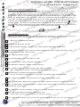
Overview/Checklist:
R
P
T of the build. You can use
COthis as a
Rsteps
KSis an overview of each of
This
the
O
R
P
O
C reference and a checklist
on the
RTcar.
KasS you button up the work
O
R
P
O
T
S
C Cover
R
K
O
R
1: Remove Intercooler
P
O
T
S
C
R
K
O
R
P
O
T
S
2: Remove
Battery
Cover
C
R
K
O
R
P
S
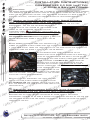
C3:ODisconnect
RT
K
O
R
Battery Terminals,
Hold Down Bracket & P
Battery.
O
T
C
KS
OR
R
O
T
C three harness loom ORKSP
R box front cover, disconnecting
4a: Remove battery
O
P
T
strap connectors
from cover.
S
C
R
K
O
R
P
O
T
C
R
KS
4b: Remove ECU cover.
O
R
P
O
T
C
R
KS
R
O
T
SPO 4c: DisconnectPthe
two
ECU
plugs.
C
OR
RK
O
T
S
C
R
K
O
5a: Disconnect
P
S
COR MAF sensor harness.
RT
K
O
R
P
O
T
S
C vehicle.
from
R5b: Remove factory airbox
K
O
R
P
O
T box from vehicle. C
Rbattery
O
RKS
5c: Unbolt and remove
P
O
Tto it!
S place - your ECU is connected
C
R
K
Put into a R
safe
O
SP
CO
RT
K
O
R
P
O
T
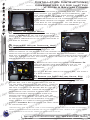
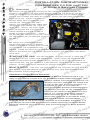
6a:
Remove
valvecover
breather
hose.
C
KS
ORTip to use bent paperclip
R
to unclasp the breather connectors.
P
O
T
S
C
R
O
P
ORK 6b: Remove factory
T
S
C
R inlet.
turbo
K accordion flex hose from
O
R
P
O
T
S plastic turbo inletPpipe.
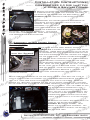
C Recirculation hose from
R
Kfactory
O
R
6c: R
Disconnect
O
T
C
KS
O
R
P
O
T
S
C bracket by
K
Disconnect factory plastic
valvecover
OR turbo inlet pipe from
T
COR 6d:
removing 10mm nut. KSP
OR
P
OR
S
C
RT
Kfactory inlet pipe.
O
R
7a: Remove
wiring harness loom clips from
P
O
T
S
C
R
K
O
R
P
O
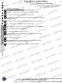
Remove boost control solenoid
C
Rup,Tnotline.
K7b:STake
O
R
P
O
care
to
pull
it
directly
on
angle.
C
RT
KS
O
R
P
O
T
C inlet pipe from turbocharger
KSand out of the vehicle.SPORT
7c: Remove plastic
R
O
T
C
OR
RK
P
O
T
S
C
R
K
O
P
T
For help with
installation,
call 360-260-CORK
(2675)
S
COR
R
K
O
R
CO
RT
O
RKSP
O
CORKSPORT
KSP
CS