1
O
RK
O
T
C
R
KSP
O Installation Instructions:
R
P
O
T
S
C
R
C
K
O
R
CorkSport MZR
P2.3 DISI Inlet Pipe ORT
O
S
C
K
R
O ORT
Ow/ Recirc & Breather Fittings
SP
C
K
R
7:
(Continued):
P
S
CO
RT
O
P
ORKR B)
T
S
C
R
tting is
K
O
R
SOLENOID
P
O
K marked
T
on diagram
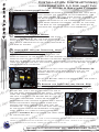
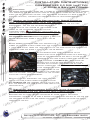
7a. Remove the hose clamp from KS
C
OR
both ends
of the line att
tting by COR
P
T
S
R
K
S KSPO
R
O
T
C
tting on the turbo
pipe and
ORinlet
P
S
COPR the boost control solenoid.
Great
care
should
be
RT
Kon the boost control
O
R
P
O
taken with the end of
the
line
T
C
R
KS
O
R
itT
is a plastic housing. If you have
O solenoidlty,Oastry
P
O
Diagram
S 7a
R rotating the hose to break the sealT C
K
R
P
O
S
then
straight up. It does take
C
Rpulling
RCORKof the rubber to the pl tting lyand
O
P
if
pulled
in
line
with
the
att
tting.
T
R
O
RKS
P
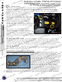
T C) Finally, we are goingCtoOremove
T
S
R
K
the plastic inlet pipe from R
the
turbocharger.
O
Tand model, the inlet pipe will most likely
SP
COhave a hose clamp
DependingO
onR
year
K
R
P
thatK
isS
actuated with a pair of pliers, but on some
models and years there is a
CO
RT
O
R
hose
clamp
with
an
8mm
bolt.
Back
the
hose
cl
lastic
P
O
C
RT
K.SThe stud that mechanically mounts
the
O
R
P
O
T
R
inlet pipe to the bracket mayC
have fallen back into place, so make sure
itSis
K
O
R
P
O
T
removed (see stepR
6d,
Page 3). Extract the plastic turbo inlet C
pipe and put it in
S
K
Obe re-used.
R
P
a box, it will
not
O
T
S
C
R
K
O
P
S
C8:ORAssembling and InstallingOthe
RT
K
Corksport
Power Series Turbo
O
R
P
T
C
Inlet Pipe.
KS
OR
R
O
T
Cclamp that holds the silicone tubing to theORKSP
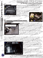
R as shown in diagram 8a. As seen, the t-bolt
Assemble the turbo inlet
pipe
band
O
P
T but still loose on the silicone coupling. TheC2”
S
turbocharger K
compressor
housing should just be tightened downR
slightly,
O
R
diameter
ared
end connects to the Corksport turbo inlet pipe,
TBoostwith the
SP2.25”
COend connects to the turbocharger whiletheRthesilicone
R
K
O
band clamp 10mm fastener tightened. Each ofO
hoses - the 6” long, smaller (ID) short hose
for
the
SbePlubricated with silicone
RT Control Solenoid and the 12” long,T
larger IDC
hose for the valvecover breather connection R
should
K
O
P
S
CO
R
O
RK
P
O
T
S
C
R
K
Oto
Caution
IDP
hose
?
S
CORshould be taken when installing theOsmaller
RT
K
O
R
P
T
S
C
Rand can bend if too much pressure is applied.
K
O
R
P
O
C
RT
O
RKS
P
O
T
S
C
R
K
O
R
OSolenoid
9: TurboCInlet
Installation, Valvecover Hose Installation
SPand
RT
K
O
R
Boost
Control
Hose
Installation.
P
O
T
C
KS
OR
R
P
O
T
S
tted
down
between
the
ECU
C
ORsimilar to the
harness and the valvecover,
P
ORK wiring
T
S
C
R
Khard plastic turbo inlet.
O
R
orientation of the factory
P
O
T
R
Feed the siliconeC
coupler end of the inlet down in
KS
O
R
P
O
T
the given
space
toward
the
turbocharger
compressor
C
Diagram8a
8a
KSDiagram
ORinlet avoiding ca
R
P
housing
ttings
and
lines
O
T
S
C
K
ORand components in the vicinity.RAlign
turbo inlet on the wiring harness
P
T
S
COR ofthethebracket
KTurbo Inlet pipe with the stud on the
on the Corksport
valvecover
O
P
O2”Rdiameter
S
bracket and connectC
the
silicone coupling over the
end
of the
RT
K
O
R
P
O
turbocharger
compressor
inlet,
taking
care
to
keep
the
loose
band
clamp
in
T
S
C is probably too tight.
R
K
R
pl SPO
ly - if not, the t-bolt band
clamp
O
C
RT
K
O
R
P
O
C
RT
KS
O
R
P
O
T
C
RT
KS
O
R
P
O
T
C
KS
OR
R
P
O
T
S
C
R
K
O
R
P
O
T
For
help
with
installation,
call
360-260-CORK
(2675)
C
R
KS
O
R
P
O
T
C
R
O
RKS