1
TDC
1/4/05
4:10 PM
Page 1
1/4/05
4:10 PM
Page 2
GUIDE TO CONTROLS
INSTALLATION
Step Three
Step Four
Panel DIN Rail Mounting
4
3
PO W E R
I N V E RT
1
7
D E L AY
--+ 2
R E L AY
6
6
4
I N V E RT
7
D E L AY
--+ 2
5
1
R E L AY
8
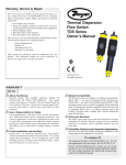
The controller may be mounted by either a back panel using two screws
through mounting holes located at the corners of the controller or by
snapping the controller on 35 mm DIN Rail.
5
2
6
INPUT1
35 mm
DIN Rail
LATCH
INPUT2B
I N P U T 2 A ONOFF
2.2"
9
9
9
1. Power indicator: This green LED lights when AC power is ON.
.275"
2. Relay indicator: This red LED will light whenever the controller
energizes the relay, in response to the proper condition at the switch
input and after the time delay.
3. AC Power terminals: Connection of 120 VAC power to the
controller. The setting may be changed to 240 VAC if desired. This
requires changing internal jumpers; this is covered in the Installation
section of the manual. Polarity (neutral and hot) does not matter.
4. Relay terminals (NC, C, NO): Connect the device you wish to
control (pump, alarm etc.) to these terminals: supply to the COM
terminal, and the device to the NO or NC terminal as required. The
switched device should be a noninductive load of not more than 10
amps; for reactive loads the current must be derated or protection
circuits used. When the red LED is ON and the relay is in the energized
state, the NO terminal will be closed and the NC terminal will be open.
3.475"
.225"
Note: Always install the controller in a location where it does not come
into contact with liquid.
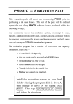
Connecting switches to input terminals:
Please note a difference between Dwyer flow switches (N-channel and
P-channel). Use only the N-Channel switches with the TDC series of
controller. Wire the Red wire to the (+) terminal and the Black wire to
the (-) terminal. Wire the White wire to the (S). See the illustration below
to indicate wiring for your switch. Reversing Red and Black wire will
change switch from NC to NO. Note: connect the Shield wire on the Flow
switch to the GND terminal if required.
INPUT
L AT C H
INPUT1
INPUT2A
ONOFF
INPUT2B
(+)
24 VDC
50 mA
Max.
7. Invert switch: This switch reverses the logic of the relay control in
response to the switch: conditions that used to energize the relay will
now de-energize the relay and vice versa.
8. Latch switch (TDC): This switch determines how the relay will
be energized in response to the two sensor inputs. When LATCH is
OFF, the relay responds to switch Input 2A only; when LATCH is ON,
the relay will energize or de-energize only when both switches (2A and
2B) are in the same condition (Flow or No-Flow). The relay will
remain latched until both switches change conditions.
(-)
(S)
14 VDC
25 mA
Max.
White
GND
FT10-XX02 FT10-XX02
GT10-XX02 GT10-XX02
NC Wiring
NO Wiring
LED Indication
Use LED's located above the input terminals to indicate whether the
switch is in a Flow or No-Flow state. With the flow switch wired NC, the
Amber LED indicates No-Flow and no LED indicates flow. Wiring the
switch NO (reversing the Red and Black wires), the Amber LED
indicates Flow and no LED indicates No-Flow.
NC Wiring
Amber
INPUT1
9. Input terminals: Connect the switch wires to these terminals:
Note the polarity: (+) is a 24 VDC, 50 mA power supply (connected to
the red wire of a Dwyer flow switch), and (-) is the common ground
path from the switch (connected to the black wire). Also, the (S) is a 14
VDC, 25 mA supply (connected to the white wire). If polarity between
the red and black wires is reversed, the switch will change from NC to
NO.
Black
Red
6. Input indicators: Use these LEDs for indicating Flow or No-Flow
status of switch. For NC wiring, an Amber LED indicates No-Flow and
no LED indicates Flow. For NO wiring, an Amber LED indicates Flow
and no LED indicates No-Flow.
White
5. Time delay: Use potentiometer to set delay from 0.15 to 60
seconds. Delay occurs during switch make and switch break.
Red
Black
TDC
NC Wiring
Off
INPUT1
NO Wiring
Amber
NO Wiring
OFF
INPUT1
INPUT1
TDC
1/4/05
4:10 PM
Page 3
INSTALLATION
TROUBLESHOOTING
Step Five
Step Six
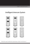
VAC Power Input Wiring
Controller Logic
Note: Polarity does not matter with the AC input terminal
For all controllers, please use the following guide to understand the
operation of the Dwyer TDC1/TDC2 controllers.
Ground
Neutral
Hot
Ground
Neutral
Hot
1. Make sure the Green power LED is On when power is supplied to the
controller.
POWER
POWER
INVERT
AC
D E L AY
-- +
AC
POWER
GND
INVERT
240 VAC, 50 - 60 Hz
R E L AY 1
D E L AY
-- +
120 VAC, 50 - 60 Hz
R E L AY 1
Relay Input Wiring
The controllers use dry contact Single Pole Double
Throw (SPDT) relays rated at 250 Volts AC, 10
Amps, 1/2 Hp. The terminals are labeled Normally
Open (NO), Common and Normally Closed (NC).
Below shows four examples of basic wiring:
RELAY OUTPUT
NO
NC
C
250 VAC, 12 A, 1/2 Hp
Alarm Contact @ No-Flow
Pump Open @ No-Flow
POWER
POWER
INVERT
D E L AY
-- +
INVERT
D E L AY
INVERT
-- +
R E L AY 1
D E L AY
-- +
R E L AY 2
INVERT
D E L AY
-- +
R E L AY 1
R E L AY 2
2. For NC switch wiring, the input LED's on the controllers will be
Amber when the switch reads No-Flow and Off when the switch
reads Flow.
3. The input LED will always respond to its corresponding relay LED.
With invert Off, the relay LED will be On when the input LED is On
and Off when the input LED is Off. With invert On, the relay LED
will be Off when the input LED is On and On when the input LED
is Off.
4. The relay may be wired either NO or NC. The normal state of the
relay is when its LED is Off. With the LED On, the relay is in the
energized mode and all terminal connections are reversed.
5. TDC model only, Latch ON operation: When both input LED's are
ON, the relay will be energized (red LED On). After that, if one
switch input turns Off, the relay will remain energized. Only when
both switch LED's are Off will the controller de-energize the relay.
The relay will not energize again until both switch LED's are ON.
Reversing Invert switch will reverse logic. See the Logic Chart
below for further explanation.
Relay Latch Logic Chart
Note: The invert is switched between the Alarm and Pump Wirings.
Normally Open
Relay Wiring
Normally Closed
Relay Wiring
Invert Off
—
POWER
INVERT
D E L AY
-- +
INVERT
POWER
D E L AY
INVERT
-- +
R E L AY 1
D E L AY
-- +
R E L AY 2
INVERT
D E L AY
-- +
R E L AY 1
Changing from 120 to 240 VAC
Remove the back panel of the controller and gently slide the printed
circuit board from the housing. Use caution when removing the PCB.
Located jumpers JWA, JWB and JWC on the PCB. To change to 240
VAC, remove jumpers from JWB and JWC and place a single jumper
across JWA. To change to 120 VAC, remove jumper JWA and place
jumpers across JWB and JWC.
240 VAC
J WA
JWB
JWC
JWC
JWB
J WA
+
On Off
Invert ON
—
Latch Off
+
On Off
Input A
InputB
Relay
Input A
InputB
Relay
ON
No Effect
ON
ON
No Effect
Off
OFF
No Effect
OFF
OFF
No Effect
On
Invert Off
Latch ON
Invert ON
Latch ON
R E L AY 2
Note: The invert is switched changes between Normally Open and
Normally Closed.
120 VAC
Latch Off
—
+
On Off
Input A
InputB
Relay
—
+
On Off
Input A
InputB
Relay
ON
ON
ON
ON
ON
Off
OFF
ON
No Change
OFF
ON
No Change
ON
OFF
No Change
ON
OFF
No Change
OFF
OFF
OFF
OFF
OFF
On
TDC
1/4/05
4:10 PM
Page 4
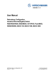
SPECIFICATIONS
Step Two
Supply voltage:
Consumption:
Sensor supply:
Relay type:
120 / 240 VAC, 50 - 60 Hz.
5 Watt
13.5 VDC @ 100 mA
TDC1: (1) SPDT
TDC2: (1) SPDT, (1) Latched SPDT
250 VAC, 10A, 1/2 hp.
Selectable, NO or NC
0 to 60 seconds
Sensor, relay & power status
Power fail-safe
F: -40 to 158
C: -40 to 70
Panel or 35 mm DIN Rail
(EN 50 022)
Polypropylene (U.L. 94 VO)
LR 79326-3 (CSA/NRTL)
Relay load:
Relay mode:
Time delay:
LED indication:
Fail safety:
Temperature range:
Enclosure rating:
Enclosure material:
Certificate number:
Dimensions
3.9"
POWER
INVERT
D E L AY
—+
INVERT
D E L AY
—+
R E L AY 2
R E L AY 1
1.8" 2.7"
LATCH
INPUT1
INPUT2A
ONOFF
INPUT2B
Functional Diagram
Relay
NC
("Relay 1"
in LC82)
C
NO
Sensor
Input
1
(+)
(-)
Latch / Invert Logic
Time Delay
+ - S
+ - S
Sensor
Input
A*
Sensor
Input
B*
S
AC
Power
Supply
AC
3.1"
3.6"
GND
Latch / Invert Logic
Time Delay
Approval Label
TDC1 Faceplate
PO W E R
I N V E RT
®
NC
("Relay 2" in LC82)
NO
Part Number Information:
Mat'l
PP
PP
Description
Flow/No-Flow Controller
Dual Flow/No-Flow Controller
D E L AY
--+
R E L AY
Relay
C
Part #
TDC1
TDC2
LR79326 -3
1
NRTL-C
Power Supply
120/240 VAC, 50 - 60 Hz
INPUT1
5 Watt
Maximum Relay Rating
250 VAC, 10 A, 1/2 Hp
Refer to the instruction
manual for installation
TDC2 Faceplate
instructions.
PO W E R
I N V E RT
D E L AY
I N V E RT
--+
R E L AY
D E L AY
--+
1
R E L AY
2
LATCH
INPUT1
I N P U T 2 A ONOFF
INPUT2B
Make a Fail-Safe System:
Design a fail-safe system that accommodates the possibility of relay or
power failure. If power is cut off to the controller, it will de-energize the
relay. Make sure that the de-energized state of the relay is the safe state in
your process. For example, if controller power is lost, a pump will turn off
if it is connected to the Normally Open side of the relay.
While the internal relay is reliable, over the course of time relay failure is
possible in two modes: under a heavy load the contacts may be “welded”
or stuck into the energized position, or corrosion may build up on a
contact so that it will not complete the circuit when it should. In critical
applications, redundant backup systems and alarms must be used in
addition to the primary system. Such backup systems should use different
sensor technologies where possible.
While this manual offers some examples and suggestions to help explain
the operation of Dwyer products, such examples are for information only
and are not intended as a complete guide to installing any specific system.