1
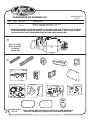
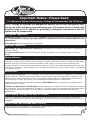
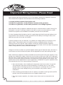
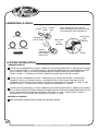
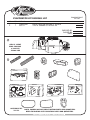
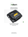
an ISO 9001:2008 Registered Company
1979-81 CAMARO
w/o FACTORY AIR
561180
901186 REV B 7/14/14, INST 1979-81 CAMARO wo AC EVAP PG 1 OF 26
Table of Contents
PAGES
1.
2.
3.
4.
5.
6.
COVER
TABLE OF CONTENTS
PACKING LIST / PARTS DISCLAIMER
INFORMATION PAGE
WIRING NOTICE
ENGINE COMPARTMENT, CONDENSER ASSEMBLY & INSTALLATION,
COMPRESSOR & BRACKETS, PULLEYS
FIGURE 1
7. PASSENGER COMPARTMENT
FIGURES 2 & 3
8. PASSENGER SIDE KICK PANEL MODIFICATION
FIGURES 4 & 4a
9. DEFROST DUCT/ FRESH AIR COVER INSTALLATION & HOSE ADAPTER
INSTALLATION
FIGURES 5, 5a & 6
10. FRESH AIR COVER INSTALLATION & KICK PANEL FRESH AIR CAP INSTALLATION
FIGURES 7, 8, 8a & 8b
11. FIREWALL COVER & EVAPORATOR BRACKET AND AC & HEATER HOSE
INSTALLATION
FIGURES 9 & 10
12. EVAPORATOR BRACKET AND HEATER FITTING INSTALLATION CONT.
FIGURE 11
13. EVAPORATOR INSTALLATION
FIGURES 12 & 12a
14. CENTER LOUVER INSTALLATION & DRAIN HOSE INSTALLATION
FIGURES 13 & 14
15. LUBRICATING O-RINGS, STANDARD HOSE KIT, & MODIFIED A/C HOSE KIT
FIGURE 15
16. HEATER HOSE & HEATER CONTROL VALVE INSTALLATION
FIGURE 16
17. FINAL STEPS AND GLOVE BOX INSTALLATION
FIGURES 17, 18 & 18a
18. CONTROL PANEL & DUCT HOSE ROUTING
FIGURE 19
19. WIRING DIAGRAM
20. GEN IV WIRING CONNECTION INSTRUCTION
21. OPERATION OF CONTROLS
22. TROUBLE SHOOTING INFORMATION
23. TROUBLE SHOOTING INFORMATION CONT.
24. KICK PANEL MODIFICATION TEMPLATE
25. GLOVE BOX LIGHT TEMPLATE
26. EVAPORATOR KIT PACKING LIST
2
901186 REV B 7/14/14, INST 1979-81 CAMARO wo AC EVAP PG 2 OF 26
EVAPORATOR KIT
561180
EVAPORATOR KIT PACKING LIST
NO.
1.
2.
QTY. PART NO.
1
1
744004-VUE
781173
DESCRIPTION
GEN IV 4 VENT EVAP. SUB CASE w/ 204 ECU
1979-81 CAMARO w/o AC ACC. KIT
** BEFORE BEGINNING INSTALLATION OPEN ALL PACKAGES AND CHECK CONTENTS OF SHIPMENT.
PLEASE REPORT ANY SHORTAGES DIRECTLY TO VINTAGE AIR WITHIN 15 DAYS. AFTER 15 DAYS,
VINTAGE AIR WILL NOT BE RESPONSIBLE FOR MISSING OR DAMAGED ITEMS.
1
GEN IV 4 VENT
EVAP. SUB CASE
w/ 204 ECU
744004-VUE
2
HI
OFF
DASH
HOT
3
ACCESSORY KIT
781173
FLR
DEF
AC
COLD
NOTE: IMA GES MA Y NOT DEPICT ACTUAL PARTS AND QUANTITIES.
REFER TO PACKING LIST FOR ACTUAL PARTS AND QUANTITIES.
901186 REV B 7/14/14, INST 1979-81 CAMARO wo AC EVAP PG 3 OF 26
Important Notice—Please Read
For Maximum System Performance, Vintage Air Recommends the Following:
NOTE: Vintage Air systems are designed to operate with R134a refrigerant only.
Use of any other refrigerant could damage your A/C system and/or vehicle, and
possibly cause a fire, in addition to potentially voiding the warranties of the A/C
system and its components.
Refrigerant Capacities:
Vintage Air System: 1.8 lbs. (1 lb., 12 oz.) of R134a, charged by weight with a quality charging station or
scale. NOTE: Use of the proper type and amount of refrigerant is critical to system operation and
performance.
Other Systems: Consult manufacturer’s guidelines.
Lubricant Capacities:
New Vintage Air-supplied Sanden Compressor: No additional oil needed (Compressor is shipped with
proper oil charge).
All Other Compressors: Consult manufacturer (Some compressors are shipped dry and will need oil
added).
Safety Switches
Your Vintage Air system is equipped with a binary pressure safety switch. A binary switch disengages the
compressor clutch in cases of extreme low pressure conditions (Refrigerant Loss) or excessively high head
pressure (406 PSI) to prevent compressor damage or hose rupture. A trinary switch combines Hi/Lo
pressure protection with an electric fan operation signal at 254 PSI, and should be substituted for use with
electric fans. Compressor safety switches are extremely important since an A/C system relies on refrigerant
to circulate lubricant.
Service Info:
Protect Your Investment: Prior to assembly, it is critical that the compressor, evaporator, A/C hoses and
fittings, hardlines, condenser and receiver/drier remained capped. Removing caps prior to assembly will
allow moisture, insects and debris into the components, possibly leading to reduced performance and/or
premature failure of your A/C system. This is especially important with the receiver/drier.
Additionally, when caps are removed for assembly, BE CAREFUL! Some components are shipped under
pressure with dry nitrogen.
Evacuate the System for 35-45 Minutes: Ensure that system components (Drier, compressor, evaporator
and condenser) are at a temperature of at least 85° F. On a cool day, the components can be heated with a
heat gun or by running the engine with the heater on before evacuating. Leak check and charge to
specifications.
Bolts Passing Through Cowl and/or Firewall:
To ensure a watertight seal between the passenger compartment and the vehicle exterior, for all bolts
passing through the cowl and/or firewall, Vintage Air recommends coating the threads with silicone prior to
installation.
Heater Hose (Not Included With This Kit):
Heater hose may be purchased from Vintage Air (Part# 31800-VUD) or your local parts retailer. Routing and
required length will vary based on installer preference.
4
901186 REV B 7/14/14, INST 1979-81 CAMARO wo AC EVAP PG 4 OF 26
Important Wiring Notice—Please Read
Some Vehicles May Have Had Some or All of Their Radio Interference Capacitors Removed.
There Should Be a Capacitor Found At Each of the Following Locations:
1. On the positive terminal of the ignition coil.
2. If there is a generator, on the armature terminal of the generator.
3. If there is a generator, on the battery terminal of the voltage regulator.
Most alternators have a capacitor installed internally to eliminate what is called “whining” as
the engine is revved. If whining is heard in the radio, or just to be extra cautious, a radio
interference capacitor can be added to the battery terminal of the alternator.
It is also important that the battery lead is in good shape and that the ground leads are not
compromised. There should be a heavy ground from the battery to the engine block, and
additional grounds to the body and chassis.
If these precautions are not observed, it is possible for voltage spikes to be present on the
battery leads. These spikes come from ignition systems, charging systems, and from
switching some of the vehicle’s other systems on and off. Modern computer-operated
equipment can be sensitive to voltage spikes on the power leads, which can cause unexpected
resets, strange behavior, and/or permanent damage.
Vintage Air strives to harden our products against these types of electrical noise, but there is
a point where a vehicle’s electrical system can be degraded so much that nothing can help.
Radio interference capacitors should be available at most auto and truck parts suppliers. They
typically are cylindrical in shape, a little over an inch long, a little over a half inch in diameter,
and they have a single lead coming from one end of the cylinder with a terminal on the end of
the wire, as well as a mounting clip which is screwed into a good ground on the vehicle. The
specific value of the capacitance is not too significant in comparison to ignition capacitors that
are matched with the coil to reduce pitting of the points.
• Care must be taken, when installing the compressor lead, not to short it to ground.
The compressor lead must not be connected to a condenser fan or to any other
auxiliary device. Shorting to ground or connecting to a condenser fan or any other
auxiliary device may damage wiring, the compressor relay, and/or cause a
malfunction.
• When installing ground leads on Gen IV systems, the blower control ground and ECU
ground must be connected directly to the negative battery post.
• For proper system operation, the heater control valve must be connected to the
ECU.
5
901186 REV B 7/14/14, INST 1979-81 CAMARO wo AC EVAP PG 5 OF 26
BEFORE STARTING THE INSTALLATION, CHECK THE FUNCTION
OF THE VEHICLE (HORN, LIGHTS,ETC.) FOR PROPER OPERATIONS.
STUDY THE INSTRUCTIONS, ILLUSTRATIONS, & DIAGRAMS.
ENGINE COMPARTMENT
REMOVE THE FOLLOWING:
BATTERY AND BATTERY TRAY (RETAIN). SEE FIGURE 1.
DRAIN RADIATOR
HOOD LATCH ASSEMBLY (RETAIN) INCLUDING HOOD LATCH SUPPORT
HEATER BLOWER MOTOR ASSEMBLY (DISCARD). TO REMOVE THE HEATER BLOWER MOTOR ASSEMBLY
(UNDER HOOD) AND THE AIR DISTRIBUTION SYSTEM (UNDER DASH), REMOVE INNER FENDER.
SEE FIGURE 3.
OEM HEATER HOSES (DISCARD). SEE FIGURE 1.
REMOVE OEM HEATER WIRING/VACUUM HARNESS MOLDED GROMMET. SEE FIGURE 1.
OUTER
FENDER
BATTERY &
BATTERY TRAY
OEM
BLOWER MOTOR
ASSEMBLY
HEATER HOSE
CLAMP
INNER
FENDER PANEL
RADIATOR
FIGURE 1
HOOD LATCH
AND SUPPORT
ASSEMBLY
OEM HEATER
WIRING/VACUUM
HARNESS
MOLDED GROMMET
CONDENSER ASSEMBLY & INSTALLATION
REFER TO SEPARATE INSTRUCTIONS INCLUDED WITH
THE CONDENSER KIT TO INSTALL THE CONDENSER.
BINARY SWITCH INSTALLATION (REFER TO CONDENSER INSTRUCTIONS)
COMPRESSOR & BRACKETS
REFER TO SEPARATE INSTRUCTIONS INCLUDED WITH
THE BRACKET KIT TO INSTALL THE COMPRESSOR BRACKET.
PULLEYS
IN MOST INSTANCES THE BELT LENGTHS WILL REMAIN THE SAME.
6
901186 REV B 7/14/14, INST 1979-81 CAMARO wo AC EVAP PG 6 OF 26
PASSENGER COMPARTMENT
NOTE: REMOVAL OF DASHBOARD IS NOT REQUIRED TO INSTALL THE EVAPORATOR. VINTAGE AIR
RECOMMENDS THAT YOU UTILIZE THE FACTORY SERVICE MANUAL WHEN YOU DISASSEMBLE
AND REASSEMBLE THE DASHBOARD.
REMOVE THE FOLLOWING:
GLOVE BOX DOOR. SEE FIGURE 3
GLOVE BOX (DISCARD, RETAIN SCREWS). SEE FIGURE 2
HEATER ASSEMBLY AND ALL RELATED DUCTING (DISCARD), RETAIN SCREWS.
SEE FIGURE 3.
DR/ PASS SIDE LOUVER OUTLETS (RETAIN). INSTRUMENT PANEL MUST BE REMOVED TO GET TO LEFT OUTLET,
AND CONTROL PANEL. SEE FIGURE 3.
CONTROL PANEL ASSEMBLY (DISCARD). SEE FIGURE 3. REFER TO CONTROL PANEL CONVERSION KIT
INSTRUCTIONS FOR INSTALLATION OF CONTROLS.
REMOVE PASS SIDE KICK PANEL (RETAIN). DISCONNECT PASS SIDE FRESH AIR CABLE FROM PANEL
SEE FIGURE 3. DISCONNECT DR/ PASS CABLE ASTRO-VENTILATION DUCTING (DISCARD).
REMOVE OEM DEFROST DUCT ASM.(DISCARD)
FIGURE 2
DR SIDE
ASTRO VENTILATION
DUCT
CONTROL
PANEL
GLOVE BOX
PASSENGER SIDE
LOUVER
INSTRUMENT
PANEL
PASS SIDE
ASTRO
VENTILATION
DUCT
ASTRO
FRESH
DRIVER SIDE
LOUVER
GLOVE BOX
DOOR
7
DR SIDE
KICK PANEL
FIGURE 3
HEATER
ASSEMBLY
901186 REV B 7/14/14, INST 1979-81 CAMARO wo AC EVAP PG 7 OF 26
PASS SIDE
KICK PANEL
PASSENGER SIDE KICK PANEL MODIFICATION
REMOVE KICK PANEL BY REMOVING THE (5) OEM SCREWS. DISCONNECT THE FRESH AIR DOOR FROM THE
LEVER HOUSING. SEE FIGURE 4
CUT KICK PANEL GRILLE USING TEMPLATE PROVIDED ON PAGE 24. SEE FIGURE 4a BELOW.
ENLARGE OEM LEVER HOUSING HOLES TO 1/2”. SEE FIGURE 4a
INSTALL (2) 1/2” PLASTIC PLUGS IN OEM LEVER HOUSING HOLES. SEE FIGURE 4a BELOW.
KICK
PANEL
(5) -OEM
SCREWS
OEM LEVER
HOUSING
KICK
PANEL
TEMPLATE
GRILLE
FIGURE 4
ENLARGE OEM
LEVER HOUSING
HOLES TO 1/2”
31102-GUR
1/2” PLASTIC
PLUG
FIGURE 4a
8
901186 REV B 7/14/14, INST 1979-81 CAMARO wo AC EVAP PG 8 OF 26
DEFROST DUCT/FRESH AIR COVER INSTALLATION
INSTALL THE DEFROST DUCTS UNDER DASH ON OEM DEFROST DUCT MOUNTING FLANGE AS SHOWN
IN FIGURE 5 BELOW. SECURE USING 10/24 x 3/8” PAN HEAD SCREW AND 10/ 24 NUT w/ STAR WASHER.
APPLY A 1/4” BEAD OF SILICONE AROUND THE BACK SIDE OF THE DR/ PASS SIDE FRESH AIR CAPS AS
SHOWN IN FIGURE 5a BELOW.
INSTALL DR/ PASS SIDE FRESH AIR CAPS SECURE USING OEM SCREWS SEE FIGURE 5 BELOW.
OEM
DEFROST DUCT
MOUNTING FLANGE
10/24 x 3/8”
PAN HEAD
SCREW
PASS SIDE
FRESH AIR
CAP
498852
DR SIDE
FRESH AIR
CAP
498851
10/24 NUT
w/ STAR WASHER
OEM
SCREWS
PASSENGER SIDE
DEFROST
DUCT
DRIVER SIDE
627171-PCA
DEFROST
DUCT
627171-PCA
FIGURE 5
FIGURE 5a
HOSE ADAPTER INSTALLATION
INSTALL (2) S-CLIPS ON HOSE ADAPTER AS
SHOWN IN FIGURE 6 BELOW.
HOSE
ADAPTER
INSTALL DRIVER & PASSENGER SIDE HOSE
ADAPTERS ON OEM LOUVERS. SEE FIGURE
6 BELOW.
(2) S-CLIPS
FIGURE 6
9
901186 REV B 7/14/14, INST 1979-81 CAMARO wo AC EVAP PG 9 OF 26
OEM
SCREWS
SILICONE
FRESH AIR COVER AND HEATER COVER BRACKET INSTALLATION
INSTALL (4) GROMMETS IN FRESH AIR CAP. SEE FIGURE 7 BELOW
APPLY A 1/4” BEAD OF SILICONE AROUND THE BACK SIDE OF THE FRESH AIR CAP AS SHOWN IN FIGURE 7.
ATTACH FRESH AIR CAP TO FIREWALL USING A 1/4-20 x 1 ½" BOLT AND WASHER, SEE FIGURE 7.
(NOTE: FRESH AIR CAP INSTALLS ON ENGINE SIDE OF FIREWALL.)
INSTALL 1 ¼” PLUG IN FIREWALL. SEE FIGURE 7.
(4) GROMMETS
33137-VUI
FRESH AIR
CAP
1/4-20 x 1 ½”
BOLT w/
WASHER
1 ¼” PLUG
33132-VUI
SILICONE
ENGINE
COMPARTMENT
FIREWALL
FIGURE 7
BACK SIDE
OF FRESH AIR
CAP
KICK PANEL FRESH AIR CAP INSTALLATION
SILICONE
INSTALL (4) GROMMETS IN KICK PANEL FRESH AIR CAP, SEE FIGURE 8a BELOW.
ROUTE A/C AND HEATER HOSE THROUGH FRESH AIR CAP AND KICK PANEL
FRESH AIR CAP AS SHOWN IN FIGURE 8 AND 8b, BELOW.
APPLY A 1/4” BEAD OF SILICONE AROUND THE BACK SIDE OF KICK PANEL
FRESH AIR CAP AS SHOWN IN FIGURE 8a, BELOW.
SECURE KICK PANEL FRESH AIR CAP USING OEM SCREWS, AS SHOWN IN
(4) GROMMETS
FIGURE 8b BELOW.
33137-VUI
BACK SIDE OF
FIGURE 8a
KICK PANEL
FRESH AIR CAP
#10 A/C
(5) OEM
HOSE
SCREWS
#10 A/C
HOSE
(2) HEATER
HOSE
#6 A/C
HOSE FIGURE 8
#6 A/C
HOSE
(2) HEATER
HOSES
FIGURE 8b
10
901186 REV B 7/14/14, INST 1979-81 CAMARO wo AC EVAP PG 10 OF 26
FIREWALL COVER INSTALLATION
ENLARGE (5) OEM FIREWALL HOLES TO 5/16”. SEE FIGURE 9 BELOW.
APPLY A 1/4” BEAD OF SILICONE AROUND THE BACK SIDE OF THE FIREWALL COVER AS SHOWN IN FIGURE 9.
FROM INSIDE THE CAR, INSTALL FIREWALL COVER ON FIREWALL. SEE FIGURE 9, BELOW. FROM THE ENGINE
COMPARTMENT SECURE FIREWALL COVER TO FIREWALL USING (4) 1/4-20 x 1”, HEX BOLTS, (5) FLAT WASHERS
AND 1/4” NUT w/ STAR WASHER. SEE FIGURE 9.
ENGINE
COMPARTMENT
SIDE OF
FIREWALL
SILICONE
(4) 1/4-20 x 1”
HEX BOLT
w/ WASHER
BACK SIDE
OF
FIREWALL
1/4” x 3/4”
COVER
FLAT WASHER
1/4” NUT
w/ STAR WASHER
NOTE: FIREWALL COVER MOUNTING
HOLES MUST BE ENLARGED.
ENLARGE (5) EXISTING HOLES
IN FIREWALL TO 5/16”
FIGURE 9
VIEW SHOWN
FROM INSIDE CAR,
THROUGH DASH
FIREWALL
COVER
644106
EVAPORATOR BRACKET AND AC & HEATER HOSE INSTALLATION
ON A WORK BENCH, INSTALL EVAPORATOR REAR BRACKET AND
AC & HEATER HOSE WITH PROPERLY LUBRICATED O-RINGS.
(SEE FIGURE 11, PAGE 12, AND FIGURES 15, PAGE 15.)
INSTALL FRONT MOUNTING BRACKET ON EVAPORATOR
USING (2) 1/4-20 x 1/2” HEX BOLTS AND TIGHTEN
AS SHOWN IN FIGURE 10 BELOW.
(2)1/4-20 x 1/2”
HEX BOLT
FIGURE 10
11
901186 REV B 7/14/14, INST 1979-81 CAMARO wo AC EVAP PG 11 OF 26
EVAPORATOR BRACKET AND HEATER FITTINGS INSTALLATION CONT.
wo AC
w/ AC
1/4-20 x 1/2” BOLT
(LOCATED ON
SUB CASE)
REAR EVAPORATOR
BRACKET ASM
644019
FIGURE 11
(2) HEATER
FITTINGS
121004
12
901186 REV B 7/14/14, INST 1979-81 CAMARO wo AC EVAP PG 12 OF 26
EVAPORATOR INSTALLATION
LIFT EVAPORATOR UNIT UP UNDER THE DASHBOARD. SEE FIGURE 12. SECURE LOOSELY TO THE FIREWALL FROM
THE ENGINE COMPARTMENT SIDE USING A 1/4-20 x 1” BOLT AND WASHER, SEE FIGURE 12 BELOW.
USING (2) #14 x 3/4” SHEET METAL SCREW SECURE THE FRONT EVAPORATOR MOUNTING BRACKET TO THE
INNER COWL. SEE FIGURE 12.
VERIFY THAT EVAPORATOR UNIT IS LEVEL AND SQUARE TO THE DASH, THEN TIGHTEN ALL MOUNTING BOLTS.
(NOTE: TIGHTEN THE BOLT ON FIREWALL FIRST, THEN THE FRONT MOUNTING BRACKET SCREWS.)
PRESS
TAPE
#10 A/C
HOSE
#6 A/C
HOSE
HEATER
HOSE
FIGURE 12a
HOSE
CLAMPS
KICK PANEL
FRESH AIR
CAP
1/4-20 x 1” BOLT
w/ WASHER
18290-VUB
(2) #14 x 3/4”
SHEET METAL
SCREW
18266-VUB
FIGURE 12
13
901186 REV B 7/14/14, INST 1979-81 CAMARO wo AC EVAP PG 13 OF 26
CENTER LOUVER INSTALLATION
REMOVE OEM CENTER LOUVER BLOCK-OFF PLATE.
INSTALL (2) OEM CENTER LOUVERS.
INSTALL (2) S-CLIPS ON CENTER LOUVER HOSE ADAPTER. SEE FIGURE 13 BELOW.
INSTALL CENTER LOUVER HOSE ADAPTER ON CENTER LOUVER AS SHOWN BELOW.
(2) OEM CENTER
LOUVERS
CENTER LOUVER
HOSE ADAPTER
625067
(2) S-CLIPS
FIGURE 13
DRAIN HOSE INSTALLATION
LOCATE EVAPORATOR DRAIN ON BOTTOM OF EVAPORATOR CASE
IN-LINE WITH THE DRAIN, LIGHTLY MAKE A MARK
ON THE FIREWALL. MEASURE ONE INCH DOWN
AND DRILL A 5/8” HOLE THROUGH THE FIREWALL.
SEE FIGURE 14.
INSTALL DRAIN HOSE TO BOTTOM OF
EVAPORATOR UNIT AND ROUTE THROUGH
FIREWALL. SEE FIGURE 14.
1”
DRAIN
HOSE
DRAIN
FIGURE 14
14
901186 REV B 7/14/14, INST 1979-81 CAMARO wo AC EVAP PG 14 OF 26
LUBRICATING O-RINGS
FEMALE
O-RING MALE
NUT
INSERT
#6 O-RING
#8 O-RING
SUPPLIED OIL
FOR O-RINGS
#10 O-RING
FIGURE 15
FOR A PROPER SEAL OF FITTINGS:
INSTALL SUPPLIED O-RINGS AS SHOWN
AND LUBRICATE WITH SUPPLIED OIL.
TWIST WITH
THIS
WRENCH
O-RING,
SLIDE OVER
MALE INSERT TO
SWAGED LIP
HOLD WITH
THIS
WRENCH
O-RING
A/C HOSE INSTALLATION
STANDARD HOSE KIT
LOCATE THE #8 COMPRESSOR A/C HOSE. LUBRICATE (2) #8 O-RINGS (SEE FIGURE 15, ABOVE) AND CONNECT
THE 90° FEMALE FITTING w/ 134a SERVICE PORT TO THE #8 DISCHARGE PORT ON THE COMPRESSOR. ROUTE
THE 45° FEMALE FITTING TO THE #8 CONDENSER HARDLINE COMING THROUGH CORE SUPPORT. SEE
FIGURE 16 PAGE 16. TIGHTEN EACH FITTING CONNECTION AS SHOWN IN FIGURE 15 ABOVE.
LOCATE THE #10 COMPRESSOR A/C HOSE. LUBRICATE (2) #10 O-RINGS (SEE FIGURE 15, ABOVE) AND
CONNECT THE #10 135° FEMALE FITTING w/134a SERVICE PORT TO THE #10 SUCTION PORT ON THE
COMPRESSOR. ROUTE THE 90° FEMALE FITTING TO THE #10 EVAPORATOR. SEE FIGURE 12a, PAGE 13 AND
FIGURE 16 PAGE 16. TIGHTEN EACH FITTING CONNECTION AS SHOWN IN 15 ABOVE.
LOCATE THE #6 EVAPORATOR A/C HOSE. LUBRICATE (2) #6 O-RINGS (SEE FIGURE 15, ABOVE) AND CONNECT
THE 90° FEMALE FITTING TO THE #6 HARDLINE COMING THROUGH THE CORE SUPPORT FROM DRIER. ROUTE
THE 90° FEMALE FITTING TO THE #6 EVAPORATOR. SEE FIGURE 12a, PAGE 13 AND FIGURE 16 PAGE 16.
TIGHTEN EACH FITTING CONNECTION AS SHOWN IN FIGURE 15, ABOVE.
MODIFIED A/C HOSE KIT
REFER TO SEPARATE INSTRUCTIONS INCLUDED WITH MODIFIED HOSE KIT.
15
901186 REV B 7/14/14, INST 1979-81 CAMARO wo AC EVAP PG 15 OF 26
HEATER HOSE & HEATER CONTROL VALVE INSTALLATION
ROUTE A PIECE OF HEATER HOSE FROM THE WATER PUMP TO THE TOP HEATER FITTING OF HEATER CORE
AS SHOWN IN FIGURE 12a PAGE 13 AND FIGURE 16 BELOW. SECURE USING HOSE CLAMPS.
COMPRESSOR
SAFETY SWITCH
(BINARY TYPE)
SCREW ON DRIER
(REFER TO
CONDENSER
INSTRUCTIONS)
FIGURE 16
#6 DRIER/
CORE HARDLINE
091679
FRO
M
MA INT
NIF AKE
OL
D
FRO
M
TO EVA
WA POR
TER
A
PU TOR
MP
#6 HOSE
096080
HOSE
HEATER
FROM HTR CNTRL VLV
TO EVAPORATOR
HOSE
CLAMPS
HEATER HOSE
(HEATER CNTRL
VALVE/ INTAKE)
TIE WRAP
#8 CONDENSER/
COMP HARDLINE
091680
#6 DRIER/
COND HARDLINE
091675
#10 SUCTION
HOSE
096073
#8 DISCHARGE
HOSE
096081
#10 ADEL
CLAMP w/
10/32 x 1/2”
PAN
HEAD SCREW
w/ NUT
NOTE: VINTAGE AIR SYSTEMS REQUIRE
(2) 5/8 HOSE NIPPLES (NOT SUPPLIED)
A/C & HEATER HOSE ROUTING
ROUTE A PIECE OF HEATER HOSE FROM THE INTAKE TO THE BOTTOM HEATER FITTING OF HEATER CORE
AS SHOWN IN FIGURE 12a PAGE 13 AND FIGURE 16 BELOW. NOTE: INSTALL HEATER CONTROL VALVE
IN-LINE WITH INTAKE MANIFOLD (PRESSURE SIDE) HEATER HOSE, SECURE USING HOSE CLAMPS AS
SHOWN IN FIGURE 16, BELOW. NOTE PROPER FLOW DIRECTION.
901186 REV B 7/14/14, INST 1979-81 CAMARO wo AC EVAP PG 16 OF 26
16
FINAL STEPS
INSTALL DUCT HOSES AS SHOWN IN FIGURE 19, PAGE 18.
INSTALL 3/8” ID GROMMET. SEE FIGURE 17.
ROUTE A/C WIRES THROUGH 3/8” ID GROMMET AS SHOWN IN FIGURE 17
(12 VOLT/ GROUND/ BINARY SWITCH/ HEATER VALVE).
INSTALL CONTROL PANEL ASM.
PLUG THE WIRING HARNESS IN THE ECU MODULE ON SUB CASE AS SHOWN IN FIGURE 19, PAGE 18
(WIRE ACCORDING TO WIRING DIAGRAM ON PAGE 19 & 20.)
INSTALL GLOVE BOX (SEE FIGURE 18)
REINSTALL ALL PREVIOUSLY REMOVED ITEMS (BATTERY TRAY & BATTERY).
FILL RADIATOR WITH AT LEAST A 50/50 MIXTURE OF APPROVED ANTIFREEZE AND DISTILLED WATER. IT IS
THE OWNERS RESPONSIBILTY TO KEEP THE FREEZE PROTECTION AT THE PROPER LEVEL FOR THE CLIMATE
IN WHICH THE VEHICLE IS OPERATED. FAILURE TO FOLLOW ANTIFREEZE RECOMMENDATIONS WILL
CAUSE HEATER CORE TO CORRODE PREMATURELY AND POSSIBLY BURST IN AC MODE AND/ OR
FREEZING WEATHER, VOIDING YOUR WARRANTY.
DOUBLE CHECK ALL FITTING, BRACKETS AND BELTS FOR TIGHTNESS.
VINTAGE AIR RECOMMENDS THAT ALL AC SYSTEMS BE SERVICED BY A CERTIFIED AUTOMOTIVE AIR
CONDITIONING TECHNICIAN.
EVACUATE THE SYSTEM FOR A MINIMUM OF 45 MINUTES PRIOR RO CHARGING AND LEAK CHECK PRIOR
TO SERVICING.
CHARGE THE SYSTEM TO THE CAPACITIES STATED ON THE INFORMATION PAGE (PAGE 4) OF THIS
INSTRUCTION MANUAL.
SEE OPERATION OF CONTROLS PROCEDURES PAGE 21.
3/8” ID
GROMMET
33144-VUI
FIREWALL
COVER
FIGURE 17
GLOVE BOX INSTALLATION
INSTALL GLOVE BOX PROVIDED, SECURE WITH OEM SCREWS THROUGH OEM HOLES. SEE FIGURE 18.
INSTALL GLOVE BOX DOOR.
NOTE: IF EQUIPPED WITH THE GLOVE BOX LIGHT AS
SHOWN BELOW IN FIGURE 18a, MODIFY PLASTIC
GLOVE BOX USING TEMPLATE PROVIDED ON PAGE 25.
GLOVE BOX
FIGURE 18a
FIGURE 18
17
901186 REV B 7/14/14, INST 1979-81 CAMARO wo AC EVAP PG 17 OF 26
CONTROL PANEL & DUCT HOSE ROUTING
BACK SIDE
OF PC BOARD
ASSEMBLY
CONTROL PANEL
HARNESS
FROM ECU
232007-VUR
PASSENGER SIDE
DEFROST DUCT
2” x 12”
FIGURE 20
DRIVER SIDE
DEFROST DUCT
2” x 22”
PASSENGER SIDE
LOUVER
2 ½” x 47”
FIGURE 19
DRIVER SIDE
LOUVER
2 ½” x 40”
CENTER LOUVER
DRIVER SIDE
2 ½” x 25”
CENTER LOUVER
PASSENGER SIDE
2 ½” x 25”
901186 REV B 7/14/14, INST 1979-81 CAMARO wo AC EVAP PG 18 OF 26
18
Wiring Diagram
232007-VUR
TAN
ORA
BLK
WHT
RED
WHT/RED
WHT/YEL
JF8
WHT/GRN
AC ANNUNCIATOR
BACKLIGHT POS
BACKLIGHT NEG
GND
5V-SW
TEMP WIPER
MODE WIPER
FAN WIPER
PRE-WIRED
VIEWED FROM WIRE SIDE
232002-VUA
A/C
(IF USED)
GEN IV ECU
GEN IV WIRING DIAGRAM
REV D, 5/6/2014
TEMP
MODE
FAN
PROGRAM
* DASH LAMP
(IF USED)
*** WIDE OPEN
THROTTLE
SWITCH
(OPTIONAL)
** CIRCUIT
BREAKER
30 AMP
HEATER
CONTROL VALVE
• Dash Lamp Is Used Only With Type 232007-VUR Harness.
• Warning: Always Mount Circuit Breaker As Close to the Battery As Possible. (NOTE: Wire Between
Battery and Circuit Breaker Is Unprotected and Should Be Carefully Routed to Avoid a Short
Circuit).
19
• Wide Open Throttle Switch Contacts Close Only at Full Throttle, Which Disables A/C
Compressor.
901186 REV B 7/14/14, INST 1979-81 CAMARO wo AC EVAP PG 19 OF 26
Gen IV Wiring
Connection Instruction
WIRING
HARNESS
CONTROL
WIRING
HARNESS
RED
&
WHITE
A/C
COMPRESSOR
RELAY
RED
BLUE
NOTE:
MOUNT RELAY
IN DESIRED
LOCATION
UNDER DASH
RED
WH
IT
E
Ignition Switch:
VIOLET
Violet 12V Ign Switch Source (Key On
Accessory) Position Must Be Switched.
+12V
NOTE:
WIRING YELLOW & ORANGE (IGNITION HOT
HARNESS COMING FROM
TERMINAL)
HARNESS ARE NOT
USED.
YELLOW
RUN
BAT
IGNITION
SWITCH
ORANGE
TAN
DASH BACK LIGHT+0-12v
GRAY
GRAY WIRE IS USED FOR
PROGRAMING CONTROLS
IF APPLICABLE
RED
GREEN
RED
GREEN
FIREWALL
BLACK BLUE
Heater Control Valve:
RED
LATCH
WIRING
HARNESS
WHITE
CHASSIS GROUND
NOTE: HEATER CONTROL
VALVE CONNECTION AND
CHASSIS GROUND MAY BE
LOCATED ON EITHER SIDE
OF THE FIREWALL. ENSURE
CONNECTOR IS LATCHED
FIRMLY.
HEATER
CONTROL VALVE
K
BLAC
BLUE
COMPRESSOR
WHITE
NOTE: CONNECT WHITE
WIRES DIRECTLY TO
(-) BATTERY TERMINAL
WHITE
RED
RED
CIRCUIT BREAKER
30 AMP
Install With Servo Motor Facing Down,
As Shown. Note Flow Direction Arrow
Molded Into Valve Body, And Install
Accordingly.
Binary/Trinary & Compressor:
Binary: Connect As Shown (Typical
Compressor Wiring). Be Sure
Compressor Body Is Grounded.
BINARY
SAFETY
SWITCH
BLUE
Dash Light:
Tan Wire Used Only With Vintage Air
Supplied Control Panel With LED Back
Light.
RED
WARNING:
ALWAYS MOUNT CIRCUIT BREAKER
AS CLOSE TO THE BATTERY AS POSSIBLE.
(NOTE: WIRE BETWEEN BATTERY AND
CIRCUIT BREAKER IS UNPROTECTED
AND SHOULD BE CAREFULLY ROUTED
TO AVOID A SHORT CIRCUIT).
+
-
Trinary Switch: Connect According To
Trinary Switch Wiring Diagram.
Circuit Breaker/Battery:
White Must Run To (-) Battery. Red May
Run To (+) Battery Or Starter. Mount
Circuit Breaker As Close to Battery As
Possible.
BATTERY
901186 REV B 7/14/14, INST 1979-81 CAMARO wo AC EVAP PG 20 OF 26
20
OPERATION OF CONTROLS
NOTE: WHEN BATTERY POWER IS FIRST CONNECTED TO THE ECU, THE COMPUTER GOES THROUGH AN
INITIALIZATION SEQUENCE. THIS INITIALIZATION MAY TAKE UP TO 30 SECONDS. A LOW BATTERY
OR DISCONNECTING THE BATTERY MAY ALSO TRIGGER A RE-INITIALIZATION. DURING START UP, A LOW
BATTERY MAY DROP BELOW 7 VOLTS, TRIGGERING RE-INITIALIZATION.
A/C MODE
BLOWER
SPEED
MODE
LEVER
BLUE
INDICATOR
LIGHT
DASH
HOT
THERMOSTAT
LEVER
BLOWER SPEED
THIS LEVER CONTROLS
THE BLOWER SPEED,
FROM OFF TO HI
A/C THERMOSTAT LEVER
IN A/C MODE SLIDE THE
THERMOSTAT LEVER ALL THE
WAY RIGHT TO THE COLD
POISTION, FOR MAXIMUM
COOLING. BLUE AC INDICATOR
LIGHT COME ON ONLY WHEN
AC COMPRESSOR IS ENGAGED
(SLIDE LEVER LEFT OR RIGHT TO
ADJUSTDESIRED TEMPERATURE)
DEFROST MODE
HEAT MODE
DASH
DASH
HOT
HOT
A/C THERMOSTAT LEVER
MODE LEVER
IN HEAT MODE SLIDE THE
SLIDE THE LEVER TO
THERMOSTAT LEVER ALL THE
THE FLR POSITION
WAY TO THE LEFT TO THE
(SLIDE THE LEVER TO
HOT POISTION, FOR MAXIMUM
THE LEFT OR RIGHT,
HEATING. (SLIDE LEVER LEFT OR
TO ADJUST DESIRED
RIGHT TO ADJUST DESIRED DASH/ FLR/ DEF LOCATION
TEMPERATURE)
21
MODE LEVER
SLIDE THE LEVER TO
THE DASH POSITION
A/C THERMOSTAT LEVER
MODE LEVER
IN DEF MODE SLIDE THE
SLIDE THE LEVER TO
THERMOSTAT LEVER ALL THE THE DEF POSITION
WAY TO THE LEFT TO THE
HOT POISTION, FOR MAXIMUM
HEATING. (SLIDE LEVER LEFT OR
RIGHT TO ADJUST DESIRED
TEMPERATURE)
901186 REV B 7/14/14, INST 1979-81 CAMARO wo AC EVAP PG 21 OF 26
901186 REV B 7/14/14, INST 1979-81 CAMARO wo AC EVAP PG 22 OF 26
Compressor will
not turn off
(All other functions
work).
3.
Compressor will
not turn on
(All other functions
work).
2.
Blower stays on
high speed when
ignition is on or off.
1b.
Blower stays on
high speed when
ignition is on.
1a.
Symptom
22
System is charged.
System is not charged.
All other functions work.
No other functions work.
Condition
Check 2-pin connector at ECU housing.
Repair or replace pot/control wiring.
Replace relay.
Check for faulty A/C
potentiometer or associated
wiring.
Check for faulty A/C relay.
Check continuity to ground on white control head wire.
Check for 5V on red control head wire.
Charge system or bypass pressure switch.
Replace BSC (This will require removal of evaporator
from vehicle).
Check to ensure that no BSC wiring is damaged or
shorted to vehicle ground. The BSC operates the blower
by ground side pulse width modulation switching. The
positive wire to the blower will always be hot. If the
“ground” side of the blower is shorted to chassis ground,
the blower will run on HI.
Be sure the small, 20 GA white ground wire is connected
to the battery ground post. If it is, replace the ECU.
Verify continuity to chassis ground with white control
head wire at various points.
Verify that all pins are inserted into plug. Ensure that no
pins are bent or damaged in ECU.
Actions
Check for disconnected or
faulty thermistor.
Check for faulty A/C
potentiometer or associated
wiring (Not applicable to 3-pot
controls).
System must be charged for
compressor to engage.
Unplug 3-wire BSC control
connector from ECU. If blower
stays running, BSC is either
improperly wired or damaged.
Unplug 3-wire BSC control
connector from ECU. If blower
shuts off, ECU is either
improperly wired or damaged.
Check for damaged ground
wire (white) in control head
harness.
Check for damaged blower
switch or potentiometer and
associated wiring.
Check for damaged pins or
wires in control head plug.
Checks
Red wire at A/C pot should
have approximately 5V
with ignition on. White
wire will have continuity to
chassis ground. White/
Blue wire should vary
between 0V and 5V when
lever is moved up or down.
Disconnected or faulty
thermistor will cause
compressor to be
disabled.
To check for proper pot
function, check voltage at
white/blue wire. Voltage
should be between 0V and
5V, and will vary with pot
lever position.
Danger: Never bypass
safety switch with
engine running. Serious
injury can result.
No other part replacements
should be necessary.
See blower switch check
procedure.
Loss of ground on this wire
renders control head
inoperable.
Notes
Troubleshooting Guide
Symptom
901186 REV B 7/14/14, INST 1979-81 CAMARO wo AC EVAP PG 23 OF 26
8.
When ignition is
turned on, blower
momentarily
comes on, then
shuts off. This
occurs with the
blower switch in
the OFF position.
Erratic functions of
blower, mode,
temp, etc.
7.
Blower turns on
and off rapidly.
6.
Loss of mode door
function.
5.
System will not
turn on, or runs
intermittently.
4.
23
This is an indicator that the
system has been reset. Be
sure the red power wire is on
the battery post, and not on a
switched source. Also, if the
system is pulled below 7V for
even a split second, the
system will reset.
Run red power wire directly to battery.
Repair or replace.
Charge battery.
Check for faulty battery or
alternator.
Battery voltage is less
than 12V.
Check for damaged switch or
pot and associated wiring.
Ensure all system grounds and power connections are
clean and tight.
Verify proper meter function by checking the condition of
a known good battery.
Check for positive power at heater valve green wire and
blower red wire. Check for ground on control head white
wire.
Install capacitors on ignition coil and alternator. Ensure
good ground at all points. Relocate coil and associated
wiring away from ECU and ECU wiring. Check for burned
or loose plug wires.
Actions
Check for at least 12V at
circuit breaker.
Check for damaged stepper
motor or wiring.
Check for obstructed or
binding mode doors.
Check for damaged mode
switch or potentiometer and
associated wiring.
Verify battery voltage is
greater than 10 volts and less
than 16.
Verify connections on power
lead, ignition lead, and both
white ground wires.
Noise interference from either
ignition or alternator.
Checks
Battery voltage is at least
12V.
Partial function of mode
doors.
No mode change at all.
Will not turn on under
any conditions.
Works when engine is not
running; shuts off when
engine is started
(Typically early Gen IV,
but possible on all
versions).
Condition
System shuts off blower at
10V. Poor connections or
weak battery can cause
shutdown at up to 11V.
Typically caused by
evaporator housing
installed in a bind in the
vehicle. Be sure all
mounting locations line up
and don’t have to be forced
into position.
Ignition noise (radiated or
conducted) will cause the
system to shut down due to
high voltage spikes. If this
is suspected, check with a
quality oscilloscope. Spikes
greater than 16V will shut
down the ECU. Install a
radio capacitor at the
positive post of the ignition
coil (See radio capacitor
installation bulletin). A
faulty alternator or worn
out battery can also result
in this condition.
Notes
Troubleshooting Guide (Cont.)
KICK PANEL MODIFICATION TEMPLATE
CUT ALONG
DOTTED LINE
CUT ALONG
DOTTED LINE
24
901186 REV B 7/14/14, INST 1979-81 CAMARO wo AC EVAP PG 24 OF 26
1 3/8”
1”
3/4”
TEMPLATE
GLOVE BOX LIGHT TEMPLATE
25
901186 REV B 7/14/14, INST 1979-81 CAMARO wo AC EVAP PG 25 OF 26
EVAPORATOR KIT
561180
EVAPORATOR KIT PACKING LIST
NO.
1.
2.
QTY. PART NO.
1
1
744004-VUE
781173
DESCRIPTION
GEN IV 4 VENT EVAP. SUB CASE w/ 204 ECU
1979-81 CAMARO w/o AC ACC. KIT
CHECKED BY:
PACKED BY:
DATE:
1
GEN IV 4 VENT
EVAP. SUB CASE
w/ 204 ECU
744004-VUE
2
HI
OFF
DASH
HOT
ACCESSORY KIT
781173
FLR
DEF
AC
COLD
NOTE: IMA GES MA Y NOT DEPICT ACTUAL PARTS AND QUANTITIES.
REFER TO PACKING LIST FOR ACTUAL PARTS AND QUANTITIES.
901186 REV B 7/14/14, INST 1979-81 CAMARO wo AC EVAP PG 26 OF 26