1
Vendo
VARI-PAK
Manual
The Vendo Company
7209 N. Ingram • Fresno, California 93650 • (559) 439-1770 • fax (559) 439-2083
Vendo P/N 1125145
Revision A
VA R I - PA K
PARTS AND SERVICE
MANUAL
TC-1
07/2003
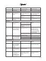
VARI-PAK TABLE OF CONTENTS
SAFETY SECTION..................................................................................... Pages S-1 - S-16
A COMMITMENT TO SAFETY.................................................................... Page S-2
VENDOR INSTALLATION ........................................................................... Pages S-3 - S-6
ELECTRICAL HAZARDS ............................................................................ Pages S-7 - S-8
MECHANICAL HAZARDS........................................................................... Page S-9
REFRIGERATION HAZARDS ..................................................................... Page S-10
SUBSTITUTIONS AND MODIFICATIONS .................................................. Pages S-11 - S-12
CONSUMER SAFETY WARNING .............................................................. Page S-13
PARTS, SALES, AND SERVICE CENTERS OF VENDO/SANDEN CO..... Pages S-14 - S-15
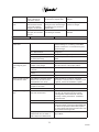
GENERAL INFORMATION......................................................................... Pages G1 - G8
GENERAL INFORMATION.......................................................................... Page G-2
INITIAL SET-UP ......................................................................................... Pages G-3 - G-4
FLAVOR STRIP INSTALLATION................................................................. Page G-5
ALIGNMENT CHECKS................................................................................ Page G-5
LOADING INSTRUCTIONS ........................................................................ Page G-6
VEND MECHANISM PARTS DESCRIPTION ............................................. Pages G-7
CLEANING INFORMATION........................................................................ Pages CL1 - CL4
CARE AND CLEANING............................................................................... Page CL-2 - CL-3
PROGRAMMING SECTION ....................................................................... Pages PG-1 - PG-24
14.1 PROGRAMMING................................................................................. Page PG-2
SET-UP AND CODE DESCRIPTION .......................................................... Pages PG-3 - PG-19
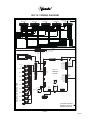
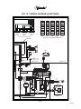
14.1 WIRING DIAGRAMS ........................................................................... Pages PG-20 - PG-21
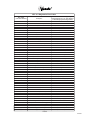
ERROR CODE CHART............................................................................... Page PG-22
SPACE TO SALES ..................................................................................... Page PG-23
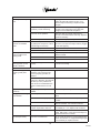
CABINET SECTION.................................................................................... Pages C-1 - C-19
READING A PARTS LIST............................................................................ Page C-2
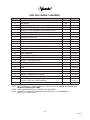
HARDWARE LIST ....................................................................................... Pages C-3 - C-5
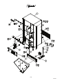
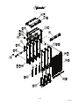
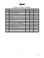
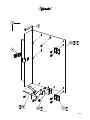
CABINET ASSEMBLY ................................................................................. Pages C-6 - C-7
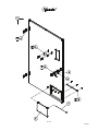
CHUTE ASSEMBLY .................................................................................... Pages C-8 - C-9
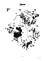
POWER BOX ASSEMBLY .......................................................................... Pages C-10 - C-11
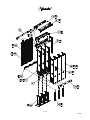
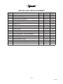
LEFT MODULE ASSEMBLY ....................................................................... Pages C-12 - C-13
RIGHT MODULE ASSEMBLY ..................................................................... Pages C-14 - C-15
REFRIGERATION ASSEMBLY ................................................................... Pages C-16 - C-17
HARNESS QUICK REFERENCE GUIDE ................................................... Pages C-18
DOOR SECTION......................................................................................... Pages D-1 - D-16
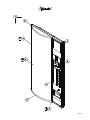
OUTER DOOR ............................................................................................ Pages D-2 - D-7
SELECTION PANEL.................................................................................... Pages D-8 - D-9
LOCK ASSEMBLY....................................................................................... Pages D-10 - D-11
COINAGE DOOR ASSEMBLY .................................................................... Pages D-12 - D-13
INNER DOOR ASSEMBLY.......................................................................... Pages D-14 - D-15
TC-2
07/2003
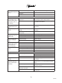
MAINTENANCE .......................................................................................... Pages M-1 - M-9
PREVENTATIVE MAINTENANCE SUGGESTIONS ................................... Page M-2
LUBRICATION GUIDE ................................................................................ Page M-2
REFRIGERATION OPERATION ................................................................. Pages M-4 – M-5
REFRIGERATION PARTS DESCRIPTION ................................................. Pages M-6 - M-8
TROUBLESHOOTING ................................................................................ Pages T-1 - T-12
VENDO WARRANTY .................................................................................. Pages T-2
PARTS RETURN PROCEDURE................................................................. Page T-3
TROUBLESHOOTING GUIDE .................................................................... Pages T-4 - T-11
TC-3
07/2003
VA R I - PA K
SAFETY SECTION
S-1
07/2003
A COMMITMENT TO SAFETY
The Vendo Company is committed to safety in every aspect of our product design. Vendo
is committed to alerting every user to the possible dangers involved in improper handling
or maintenance of our equipment. The servicing of any electrical or mechanical device
involves potential hazards, both to those servicing the equipment and to users of the
equipment. These hazards can arise because of improper maintenance techniques.
The purpose of this manual is to alert everyone servicing Vendo equipment of potentially
hazardous areas, and to provide basic safety guidelines for proper maintenance.
This manual contains various warnings that should be carefully read to minimize the risk
of personal injury to service personnel. This manual also contains service information
to insure that proper methods are followed to avoid damaging the vendor or making it
unsafe. It is also important to understand these warnings are not exhaustive. Vendo
could not possibly know, evaluate, or advise of all of the conceivable ways in which service
might be done. Nor can Vendo predict all of the possible hazardous results. The safety
precautions outlined in this manual provide the basis for an effective safety program.
Use these precautions, along with the service manual, when installing or servicing the
vendor.
We strongly recommend a similar commitment to safety by every servicing organization.
Only properly-trained personnel should have access to the interior of the machine.
This will minimize the potential hazards that are inherent in electrical and mechanical
devices. Vendo has no control over the machine once it leaves the premises. It is the
owner or lessor’s responsibility to maintain the vendor in a safe condition. See Section
I of this manual for proper installation procedures and refer to the appropriate service
manual for recommended maintenance procedures. If you have any questions, please
contact the Technical Services Department of the Vendo office nearest you.
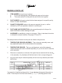
SAFETY RULES
•
•
•
•
•
•
•
•
•
Read the Safety Manual before installation or service.
Test for proper grounding before installing to reduce the risk of electrical shock and
fire.
Disconnect power cord from wall outlet or air dam before servicing or clearing product
jams. The vending mechanism can trap and pinch hands.
Use only fully-trained service technicians for Power-On servicing.
Remove any product prior to moving a vendor.
Use adequate equipment when moving a vendor.
Always wear eye protection, and protect your hands, face, and body when working
near the refrigeration system.
Use only authorized replacement parts.
Be aware of inherent dangers in rocking or tipping a vending machine.
S-2
07/2003
SECTION I: VENDOR INSTALLATION
A.
Vendors are large, bulky machines of significant size and weight. Improper
handling can result in injury. When moving a vendor, carefully plan the route to be
taken and the people and equipment required to accomplish the task safely.
B.
Remove all tape, shipping sealant, and Styrofoam from the vendor. Loosen
any shipping devices used to secure interior parts during shipping. Remove the
wooden shipping base attached to the vendor base by the vendor leveling screws.
Make certain the leveling screws are in place and functional.
C.
Position the vendor three to four inches (7.6 cm to 10.2 cm) from a well-constructed
wall (of a building or otherwise) on a flat, smooth surface.
IMPORTANT: The vendor requires three inches (7.6 cm) of air space from the wall
to ensure proper air circulation to cool the refrigeration unit.
D.
Adjust the leveling screws to compensate for any irregularities on the floor surface.
Ideally, no adjustment will be necessary and the leveling legs will be flush with the
bottom of the vendor. A spirit level is a useful aid to level the vendor. When the
outer door is open, it will remain stationary if the vendor is properly leveled. Vendors
must be level to ensure proper operation and to maintain stability characteristics.
Do not add legs to the vendor. The leveling legs shall not raise the vendor
more than 1 1/8 inch above the ground.
E.
Check the manufacturer’s nameplate on the left or right side of the vendor’s cabinet
to verify the main power supply requirements of the vendor. Be sure the main
power supply matches the requirements of the vendor. To ensure safe operation,
plug the vendor only into a properly grounded outlet.
DO NOT USE EXTENSION CORDS.
F.
Recommended voltage specs = volts required + amps of circuit.
NOTE:
Any power supply variance more than + 10% may cause the vendor to
malfunction.
*
Power outlets must be properly grounded.
*
Power outlets must be properly polarized, where applicable.
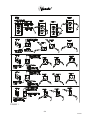
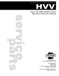
Test the outlets using the following information.
(Refer to Figure 1 on Page S-4.)
S-3
07/2003
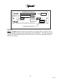
FIGURE 1
S-4
07/2003
SECTION I: VENDOR INSTALLATION (CONTINUED)
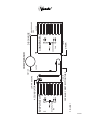
For Type 1 and Type 2 outlets, test for Grounding and Polarization as follows:
1.
With a test device (volt meter or test light), connect one probe to the receptacle’s
neutral contact and the other to the live contact. The test device should show a
reaction.
2.
Connect one probe to the receptacle’s earth contact and the other to the live
contact. The test device should show a reaction.
For Type 3 through Type 5 outlets, test for Grounding as follows:
1.
2.
With a test device (volt meter or test light), determine which of the receptacle’s
power contacts is the live contact.
A.
Connect one probe to the receptacle’s earth contact.
B.
Connect the second probe to the left (or upper) power contact. If a
reaction occurs, this is the live power contact. If a reaction does not occur,
move the second probe to the right (or lower) contact. A reaction should
occur, indicating that this is the live power contact.
Connect one probe to the receptacle’s live power contact (as determined in step
1). Connect the second probe to the other power contact (neutral). The test
device should show a reaction.
IF THE ABOVE CONDITIONS ARE NOT MET FOR THE GIVEN OUTLET
TYPE, CONTACT A LICENSED ELECTRICIAN AND HAVE THE
NECESSARY CORRECTIONS MADE.
S-5
07/2003
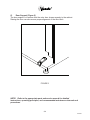
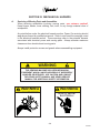
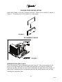
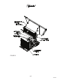
G.
Door Support (Figure 2)
The door support is to ensure that the outer door closes squarely to the cabinet.
Raising the door can also ensure proper alignment of the door latch.
FIGURE 2
NOTE: Refer to the appropriate parts and service manual for detailed
instructions, operating principles, and recommended maintenance intervals and
procedures.
S-6
07/2003
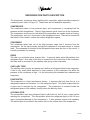
SECTION II: ELECTRICAL HAZARDS (CONTINUED)
GENERAL
Vendo vending machines are provided with the appropriate power supply setting for your
area. Some models are equipped with step-down transformers, as required. This enables
the vending machine to operate on different main voltages. Refer to Section I. E. for
information to determine the main power requirements. Refer to the appropriate service
manual for details of step-down transformer operations.
The power sources just mentioned are standard for both household and commercial
lighting and appliances. However, careless or improper handling of electrical circuits
can result in injury or death. Anyone installing, repairing, loading, opening, or otherwise
servicing a vending machine should be alerted to this point. Apply all of the normal
precautions observed in handling electrical circuits, such as:
•
•
•
•
•
•
A.
Refrigeration servicing to be performed by qualified personnel only.
Unplug the vendor or move power switch to off position before servicing or clearing
product jams.
Replace electrical cords if there is any evidence of fraying or other damage.
Keep all protective covers and ground wires in place.
Plug equipment into outlets that are properly grounded and polarized (where
applicable), and protected with fuses or circuit breakers.
All electrical connections must be dry and free of moisture before applying power.
Grounding Systems
Vendo vending machines are provided with the appropriate service cord for the
power supply in your area. The service cord will connect to the matching electrical
outlet. Always ensure that the outlet to be used is properly grounded before
plugging in the vendor. (See pages S-3 through S-5.)
WARNING
ALWAYS TEST TO VERIFY PROPER GROUNDING PRIOR TO
INSTALLATION TO REDUCE THE RISK OF ELECTRICAL
SHOCK AND FIRE
The electrical grounding system also includes the bonding of all metal components
within the vendor. This involves a system of bonding wires identified by green or green
and yellow marking. The system uses serrated head screws, lock washers, and star
washers to ensure the electrical connection between parts. Maintenance of vending
equipment may involve disassembly. Include the above items when reassembling, even
if the vending machine may appear to function normally without them. Omitting any of
these items can compromise a link in the grounding system. See the appropriate service
manual or kit instructions for components and assembly instructions.
S-7
07/2003
SECTION II: ELECTRICAL HAZARDS (CONTINUED)
B.
Servicing with “Power Off”
For maximum safety, unplug the service cord from the wall outlet before opening
the vendor door. This will remove power from the equipment and avoid electrical
and mechanical hazards. Service personnel should remain aware of possible
hazards from hot components even though electrical power is off. See the
appropriate sections of this manual for further information.
C.
Servicing with “Power On”
Some service situations may require access with the power on. Power on servicing
should be performed only by fully-qualified service technicians. Particular
caution is required in servicing assemblies that combine electrical power and
mechanical movement. Sudden movement (to escape mechanical action) can
result in contact with live circuits and vice versa. It is therefore doubly important
to maintain maximum clearances from both moving parts and live circuits when
servicing.
WARNING
“POWER ON” SERVICING SHOULD BE ACCOMPLISHED ONLY BY
FULLY-TRAINED PERSONNEL. SUCH SERVICE BY UNQUALIFIED
INDIVIDUALS CAN BE DANGEROUS.
Power to lighting and refrigeration system is shut off automatically by the electronic
controller when the outer door is opened.
NOTE:
For power-on servicing of the vendor’s lighting system, turn lighting power on by
accessing the Lights test function of the electronic controller (see programming
on inner door).
For power-on servicing of the vendor’s refrigeration system, turn refrigeration
power on by accessing the Compressor test function of the electronic controller
(see programming on inner door).
S-8
07/2003
SECTION III: MECHANICAL HAZARDS
A.
Servicing of Moving Parts and Assemblies
When servicing assemblies involving moving parts, use extreme caution!!
Keep fingers, hands, loose clothing, hair, tools, or any foreign material clear of
entrapment.
As noted before under the electrical hazards section, Power On servicing should
only be performed by qualified personnel. Refer to and heed the warnings noted
in the electrical hazards section. These warnings refer to the potential hazards
associated with electrical power and moving parts. Always maintain maximum
clearances from electrical and moving parts.
Always install protective covers and guards when reassembling equipment.
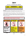
WARNING
THIS VENDING MACHINE INCLUDES MECHANICAL
EQUIPMENT WHICH CAN BE HAZARDOUS IF IMPROPERLY
HANDLED OR SERVICED. USE CAUTION AND CONSULT
THE VENDO SAFETY MANUAL AND VENDO SERVICE
MANUAL FOR ADDITIONAL SAFETY INFORMATION.
WARNING
WARNING
RISK OF ENTRAPMENT!
RISK OF SHOCK!
ELECTRICAL!
S-9
07/2003
SECTION IV: REFRIGERATION HAZARDS
GENERAL
Refrigeration systems involve both electrical power and mechanical action. These
systems may present any of the potential dangers shown in the sections on electrical
and mechanical hazards contained in this manual. See Sections II and III for further
information.
A.
Compressed Refrigerant
Refrigeration systems involve the compression and evaporation of gases. The
pressures contained represent a potential hazard if suddenly released in confined
areas. Caution is required when performing maintenance tests or repairs. All
testing of sealed refrigeration systems must be done by trained personnel who are
familiar with the systems and pressures involved.
B.
Physical Protection
The accidental release of refrigerant gases can result in physical injuries. Always
wear protective glasses and protect your hands, face, and body when working
near the refrigeration system.
WARNING
ALWAYS WEAR EYE PROTECTION AND PROTECT YOUR
HANDS, FACE, AND BODY WHEN WORKING NEAR
THE REFRIGERATION SYSTEM
SECTION V: TEMPERATURE HAZARDS
GENERAL
Maintenance personnel should be alerted to the potential hazards from hot metal
surfaces. High temperatures may be present throughout the refrigeration system even
though electrical power has been removed.
S-10
07/2003
SECTION V: SUBSTITUTIONS AND MODIFICATIONS
GENERAL
Unauthorized changes or the substitution of unauthorized parts can compromise the
equipment designs. This can result in unsafe conditions for either the service personnel
or the equipment users. Always refer to the appropriate parts and service manual for
replacement parts and maintenance instructions. If questions arise, contact the Technical
Services Department of the Vendo office in your area.
When servicing the vending machine, always reassemble all components to their original
location and position. Maintain the correct routing for tubing, electrical wiring, etc..
Replace all clamps, brackets, and guides to their original locations. Replace all tubing,
sleeving, insulating material, and protective covers to their original condition.
WARNING
VENDO EQUIPMENT HAS BEEN PROVIDED WITH APPROPRIATE PROTECTIVE
DEVICES TO PROTECT AGAINST THE POSSIBILITY OF OVERHEATING AND
FIRE AS A RESULT OF EQUIPMENT OR COMPONENT FAILURES.
SUBSTITUTION, MODIFICATION, OR BYPASSING OF SUCH PROTECTIVE
DEVICES CAN CREATE DANGEROUS CONDITIONS. PROTECTIVE CIRCUITS
SHOULD NEVER BE BYPASSED, AND FAILED PROTECTIVE DEVICES MUST
BE REPLACED ONLY WITH FACTORY-AUTHORIZED PARTS.
A.
Service Cord Replacement
Vendo vending machines are furnished with unique power supply cords. If
replacement becomes necessary, consult the appropriate parts and service
manual and order the correct replacement cord for the model of vending machine
in question. Do not use substitute replacement cords. Only authorized service
personnel with appropriate training should replace the vending machine service
cord. If a question should arise concerning which service cord to order, contact the
Technical Services Department of the Vendo office in your area.
S-11
07/2003
SECTION V: SUBSTITUTIONS AND MODIFICATIONS (CONTINUED)
WARNING
THIS APPLIANCE MUST BE EARTHED.
IMPORTANT!
The wires in the main leads are colored in accordance with the following code:
110v/120v
Green
White
Black
220v/240v
Green and Yellow............................. Earth
Blue ................................................... Neutral
Brown................................................ Live
S-12
07/2003
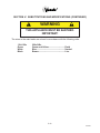
SECTION VI: CONSUMER SAFETY WARNING
WARNING
VENDOR CAN BE OVERTURNED IF SUFFICIENT FORCE IS
APPLIED AND MAY RESULT IN SERIOUS INJURY OR DEATH.
GENERAL
There have been incidents, including fatalities, when vending machines have been
vandalized by being pulled over in an attempt to obtain free product or money.
To warn of the danger involved in tipping, shaking, or rocking the vending machine, a decal
has been designed to be affixed to vending machines. (One such decal is applied on the
vending machine.) Vendo will supply sufficient decals to be placed on all machines, on
request. If you have any questions, contact the Technical Services Department of the
Vendo office in your area.
THE FOLLOWING DECAL SHOULD BE PLACED IN A POSITION
ON THE VENDOR CONTROL PANEL AT EYE LEVEL
S-13
07/2003
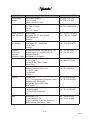
AREA
United States,
Canada
ADDRESS
The Vendo Company
7209 N. Ingram
Fresno, CA 93650 U.S.A.
Japan
Sanden International Corporation
31-7 Taito 1-Chome
Taito-ku
Tokyo 110, Japan
Europe, Mid-East Vendo GMBH
Africa, Mid-Asia
Spangerstr. 22, P.O. Box 130940
40599 Dusseldorf
Germany
Australia,
Sanden International Pty. Ltd.
New Zealand
54 Allingham St., Condell Park
N.S.W. 2200
Australia
Singapore,
Sanden International (Singapore) Pte., Ltd.
Sanden House, 25, Ang Mo Kio St. 65
Hong Kong,
Indonesia,
Singapore 569062
Phillippines, India The Republic of Singapore
Taiwan
Sanden International Taiwan Corp.
No, 21-6, Sec 1
Tun Hwa S. Rd., Taipei, Taiwan
Taiwan, ROC
Belgium
N.V. Vendo Benelux, S.A.
Industrial Research Park N.O.H.
13 Font St. Landry
1120 Brussels
Belgium
England
Vendhall, Ltd.
Unit 17, The Basingstoke Enterprise Centre
Westham Lane, Worting Rd,
Basingstoke, Hants RG22, 6NQ
Great Britain
Italy
Vendo Italy S.p.A.
Casella Postale 9
1-15033 Casale Monferrato
Italy
Spain
Vendo Iberia, S.A.
C/ Sant Ferran No. 92
Poligono Industrial la Almeda, Sector P-1
08940 Cornella, (Barcelona), Spain
S-14
PHONE NUMBERS
Tel: (559) 439-1770
Fax: (559) 439-2083
Tel: (81) 3-3835-1321
Fax: (81) 3-3833-7096
Tel: (49) 211-74-039-0
Fax: (49) 211-7488541
Tel: 61-2-9791-0999
Fax: 61-2-9791-9029
Tel:
Fax:
65-482-5500
65-482-1697
Tel: 886-2-570-6106
Fax: 886-2-577-1959
Tel: 32-2-268-2595
Fax: 32-2-268-2862
Tel: 44-1256-479309
Fax: 44-1256-844469
Tel: 39-142-335111
Fax: 39-142-5623-48
Tel: 343-474-1555
Fax: 343-474-1842
07/2003
AREA
Mexico
Central America
Chile
Brazil
South America
ADDRESS
Vendo de Mexico
Camino Real de Toluca No. 154
Col. Bellavista
01140 Mexico D.F. Mexico
The Vendo Company
7209 N. Ingram
Fresno, CA 93650 U.S.A.
Pelp Internacional, S.A.
4560 El Rosal
Huechuraba, Santiago, Chile
Cimaq Industria e Comercio de Maq, Ltda.
Estrada Uniao e Industria, 9.120 Itaipava
25730-730 Petropolis
Rio de Janeiro, Brazil
The Vendo Company
7209 N. Ingram Ave.
Fresno, CA 93650 U.S.A.
S-15
PHONE NUMBERS
Tel: (525) 515-9745
Fax: (525) 277-0111
Tel: (559) 439-1770
Fax: (559) 439-2083
Tel: (562) 243-9710
Fax: (562) 740-0504
Tel: (55242) 22-2666
Fax: (55242) 22-3244
Tel: (559) 439-1770
Fax: (559) 439-2083
07/2003
NOTES
S-16
07/2003
VA R I - PA K
GENERAL INFORMATION
SECTION
G-1
07/2003
This manual contains programming, operation, and complete parts and electrical wiring
diagrams.
The controller is a microprocessor which will permit pricing per selection from 0.00 to
99.99. This machine also has space-to-sales programming as well as energy savings
modes.
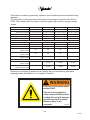
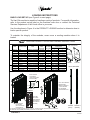
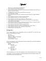
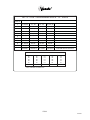
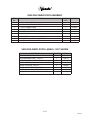
VARI-PAK MODEL NUMBER
450
453
455
457
Selections
10
10
10
10
Dimensions (HxWxD) 72” x 39.5” x 34.75” 72” x 39.5” x 34.75” 72” x 39.5” x 34.75” 72” x 39.5” x 34.75”
Medium Cassettes (330ml)
Larger Cassettes (500ml)
Shipping Weight
5
3
2
0
0
1
2
4
642 lbs
642 lbs
642 lbs
642 lbs
72
72
72
~
Capacity: Medium Cassette
12 oz. Can
102
102
102
~
325 ml Plastic Bottle
250 ml Can
66 (est)
66 (est)
66 (est)
~
330 ml Tetra Prisma®
Aseptic Carton
90
90
90
~
236 ml Tetra Prisma®
Aseptic Carton
96
96
96
~
250 ml Tetra Brik®
Aseptic Carton
132
132
132
~
500 ml Tetra Prisma®
Aseptic Carton
~
72 (est)
72 (est)
72 (est)
500 ml Tetra Prisma®
Aseptic Carton w/ Cap
~
72 (est)
72 (est)
72 (est)
Capacity: Large Cassette
Dimensions and shipping weight will vary slightly due to manufacturing tolerances,
shipping boards and whether or not coinage is installed.
WARNING
Load this unit with shelf-stable
product ONLY.
This unit is not equipped to
safely vend perishable product.
Loading this unit with improper
product may result in serious
illness or injury to the
consumer.
1125135
G-2
07/2003
INITIAL SET-UP
A. UNPACKING
Remove all plastic film, cardboard and tape from the outside of the vendor. Loosen any
shipping devices used to secure interior parts during shipment (backspacer, shims or
spacers).
To remove shipping boards from base, raise vendor on a well-stabilized lifting device.
Remove the leveling bolts which hold the boards in place and remove the boards. Replace bolts to equal heights in the threaded holes. Another method to remove shipping
boards is to split the boards apart. Using a pinch bar or a heavy screwdriver and hammer, insert tool into the slots and force the boards apart. The leveling legs shall not
raise the vendor more than 1 1/8 inch above the ground.
B. POSITIONING
IMPORTANT: PLACE THE VENDOR IN DESIRED LOCATION AT LEAST THREE
INCHES (7.6CM) AWAY FROM ANY REAR OBSTRUCTION. This is for proper air flow
through the refrigeration compartment. The refrigeration system requires rear to front air
circulation for proper operation.
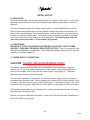
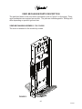
C. POWER SUPPLY CONNECTION
CAUTION: DO NOT USE AN EXTENSION CORD!
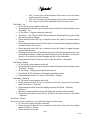
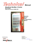
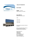
The vendor’s power requirements will vary depending upon the country it was purchased for. To verify the power requirements of the vendor, check the serial plate located on the hinged side of the outer door (see Figure 4 on page G-4). The power
requirements are listed on the serial plate.
To insure safe operation of the vendor, the vendor’s power supply must be a properly
grounded and polarized outlet. Before plugging the vendor into the outlet, test the outlet
to confirm it will meet the vendor’s power requirements. If the power supply of the outlet
is different from the power requirements of the vendor, a transformer may be necessary.
If the power requirements are not properly met, contact a licensed electrician and have
the necessary correction made.
Should you require additional information, contact the Technical Services Department of
the Vendo office in your area.
G-3
07/2003
APPROVED FOR OUTDOOR USE
MODEL
BASIC
UNIT
SERIAL NO.
CHARGE
OZ. R-134a
DESIGN PRESSURE - PSIg
LOW SIDE 90 HIGH SIDE 295
REFRIGERATED
VENDING MACHINE
239L
MFD IN U.S.A. BY THE VENDO CO., FRESNO, CA.
AMPS
105/115
50/60
1
VOLTS
CYCLE
PHASE
POWER REQUIREMENTS
FIGURE 1
NOTE: The Model number of the vending machine is located on the top, left hand corner
of the serial plate. A typical model number could read “450VPV001”. The 450 is the model
number, VPV represents the product line of the vendor, and the remaining digits tell what
options are included.
G-4
07/2003
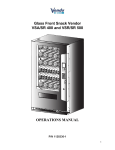
FLAVOR STRIP INSTALLATION
Insert flavor labels to the top of selection window. A rear view of window is shown in
Figure 2. The arrow points to the direction to insert labels.
FIGURE 2
ALIGNMENT CHECK
FIGURE 3
REFRIGERATION AREA CHECK:
Check the position of the condensation pan (see Figure 3). The correct position of the
pan is on the right hand side of the vendor with the ramp of the pan just outside the
right hand air dam. Be sure the drain tube is attached to the pan and is free of kinks. A
water trap is installed into the condensation pan and will prevent warm, moist air from
reaching the evaporator area.
G-5
07/2003
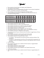
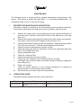
LOADING INSTRUCTIONS
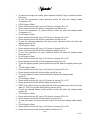
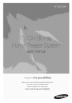
BASIC LOAD SET-UP (see Figure 4 on next page):
The Vari-Pak machine is capable of vending a variety of products. For specific information,
refer to the product set-up label on the machine inner door or contact the Technical
Services Department of the Vendo office in your area.
Use the directions in Figure 4 in the PRODUCT LOADING section to determine how to
load a specific product.
To maintain the integrity of the modules, never move a vending machine when it is
loaded.
500 mL
MODULE
300 mL
MODULE
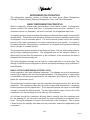
VARI-PAK PRODUCT SETUP AND LOADING INSTRUCTIONS
SIZE
DESCRIPTION
TYPE
125 mL
200mL
200 mL
200 mL
250 mL
250 mL
330 mL
12 OZ
250 mL
500 mL
16 OZ
12 OZ
12 OZ
BRIK
BRIK
BRIK SLIM
BRIK MID-SIZE
BRIK
PRISMA
PRISMA
STANDARD
STANDARD
PRISMA
STANDARD
DASANI*
AQUAFINA*
ASEPTIC CARTON
ASEPTIC CARTON
ASEPTIC CARTON
ASEPTIC CARTON
ASEPTIC CARTON
ASEPTIC CARTON
ASEPTIC CARTON
CAN
CAN
ASEPTIC CARTON
CAN
PET BOTTLE
PET BOTTLE
BACK SPACER
POSITIONS
SIDE
COLUMN
LEFT
RIGHT
SPACER SETTING
1
1
1125100
4
3
3
NONE
5
NOT USED NOT USED
1125100
4
NOT USED NOT USED
1125096�
4
NOT USED NOT USED
NONE
5
NOT USED NOT USED
1125100
4
NOT USED NOT USED
1125096�
5
NOT USED NOT USED
NONE
6
NOT USED NOT USED
1125096�
2
NOT USED NOT USED
NONE
6
NOT USED NOT USED
NONE
6
NOT USED NOT USED
NONE
6
NOT USED NOT USED
NONE
6
SIDE SPACERS
0.3"
SIDE
SPACER
1125096
0.6"
SIDE
SPACER
1125100
BACK SPACERS
* LOAD CAP END FIRST
BACK SPACER
LOCATIONS
(TWO LOCATIONS
PER COLUMN)
4 3 2 1
1. PULL OUT MODULE.
2. OPEN DOOR.
3. INSERT PRODUCT
INTO COLUMN.
4. CLOSE DOOR.
5. PUSH MODULE IN.
1
COLUMN
SETTINGS
5
10
9
8
7
6
5
4
3
COLUMN
SETTINGS
ARE MARKED
ON MODULE
(SETTING #3
SHOWN)
3
2
2
SIDE SPACER
1
LOCATIONS
(SIX LOCATIONS
4
PER MODULE)
For questions regarding product settings not shown, contact the Vendo Technical Services Department
at 1-800-344-7216 ext.3368 (US/Canada) or 559-439-1770 ext.3368.
FIGURE 4
G-6
1125299
(LEFT)
1125299-1
(RIGHT)
07/2003
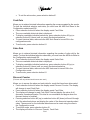
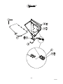
VEND MECHANISM PARTS DESCRIPTION
The part listed below is the vend motor mechanism (refer to Figure 5 on this page). Three
vend mechanisms are required per module. The parts are interchangeable. Settings will
differ depending on product type and size.
VEND MECHANISM ASSEMBLY: P/N 1124288
The motor is attached to the module by screws.
FIGURE 5
G-7
07/2003
NOTES
G-8
07/2003
VA R I - PA K
CLEANING INFORMATION
SECTION
CL-1
07/2003
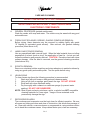
CARE AND CLEANING
DO NOT USE WATER JET FOR CLEANING.
AVOID USING WATER OR ANY OTHER LIQUIDS NEAR
ELECTRONIC COMPONENTS
A.
GENERAL PROCEDURE (painted metal areas)
Wash the vendor with soap and water. The exterior may be waxed with any good
automobile wax.
B.
FRESH PAINT SPLASHES, GREASE, GLAZING COMPOUND REMOVAL
Before drying, these elements may be removed by rubbing lightly with grade
“A” Naptha (or equivalent grade solvent). After removal, use general cleaning
procedure (listed above in A).
C.
LABELS AND STICKER REMOVAL
Use any specialized label removal liquid. When the label material does not allow
penetration of solvent (such as vinyl), the application of heat (ie – hot air gun) will
soften the adhesive and promote removal. CAUTION: Excessive heat can cause
surface damage. After the label is removed, use the general cleaning procedure
(listed above in A).
D.
SCRATCH REMOVAL
Remove or minimize hairline scratches and minor abrasions in painted surfaces by
using any good quality automobile polish. Test the polish before using.
E.
LEXAN SIGNS
To clean Lexan sign faces the following procedure is recommended.
1.
Wash sign with mild soap or detergent and lukewarm water.
2.
Using a soft cloth or sponge, gently wash the sign. DO NOT SCRUB!
3.
Rinse well with clean lukewarm water.
4.
Dry thoroughly with a chamois or cellulose sponge (to prevent water
spotting). DO NOT USE SQUEEGEE!
NOTE: Most organic solvents, petroleum, spirits, or alcohol are NOT compatible
cleaning materials for Lexan signs. Usage of those materials could
permanently damage the sign.
F.
REFRIGERATION AREA
The condenser and evaporator must be kept clean for efficient operation. Be sure
all vanes and tubing are clean and clear of obstruction; this allows free passage of
air. Clean with a brush, a vacuum cleaner or compressed air, using extreme caution
not to bend the condenser vanes. Keep cabinet drain open; clean as necessary.
CL-2
07/2003
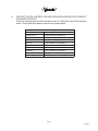
G.
PRODUCT CHUTE, HOPPER, & OTHER INTERIOR SURFACES THAT CONTACT
PACKAGED PRODUCT
Wash the surfaces with a mild food safe soap (i.e. Palmolive Liquid Dish Soap) &
water. Rinse with plain water to remove any soap residue.
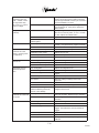
Recommended Cleaning Schedule
Vendor Area
Frequency
Product Chute
Monthly and when spills occur
Hopper/Delivery Port
Weekly and when spills occur
Exterior Cabinet/Door
Every 6 months or as needed
Sign Face
Every 6 months or as needed
Cabinet Interior
Every 6 months or as needed
Door Interior
Every 6 months or as needed
Condenser
Every 3 months or as needed
Evaporator
As required
Modules
Every 6 months and when spills occur
CL-3
07/2003
NOTES
CL-4
07/2003
VA R I - PA K
14.1 PROGRAMMING
SECTION
PG-1
07/2003
VEC 14.1 CONTROL BOARD OPERATION
The VEC 14.1 controller operates via a 4-button programming system:
Selection Button #1 – Return
Selection Button #2 – Increase/Move Forward
Selection Button #3 – Decrease/Move Backward
Selection Button #4 - Enter
In order to access the mode functions, open the inner door. Locate the mode button.
Press the mode button one time. Selection Button #2 will take you through the modes.
The available modes are:
Diagnostics
Coin Payout
Tube Fill
Test Mode
Cash Data
Sales Data
Discount Counter
Free Counter
Set Price
Configuration
Space to Sales
Door Closed Password
Set Language
Set Clock *
Lighting *
Refrigeration**
Sales Block 1 *
Sales Block 2 *
Discount *
Override **
Custom Message
Return
* These modes will only appear when the Timing Features in Configuration are turned
ON.
** Limited options will appear in these modes depending on whether the Timing Features
are ON/OFF.
PG-2
07/2003
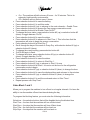
Diagnostics
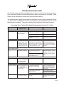
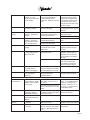
See attached error code chart on page PG-22 for errors and how to clear them.
When you enter into the Diagnostics mode with selection button #4, the first one of the
summary error codes will be displayed. If no errors have occurred since the last error reset,
the display will show an Error None message. Pressing selection button #2 (up) or selection
button #3 (down) will cycle through all of the summary error codes. Pressing selection button
#4 will allow access into the detailed error code, while pressing selection button #1 returns to
the Diagnostics display.
Coin Payout
Allows you to payout coin tubes.
• Press selection button #4 to enter into Coin Payout mode.
• Press selection button #2 (up) or selection button #3 (down) to choose denomination.
• Press selection button #4 to dispense displayed denomination.
• Press selection button #1 to exit mode.
Tube Fill
Allows you to fill coin tubes via external coin insert. This is the recommended way to fill the
coin tubes because the control board is able to keep an accurate count of the coins.
• Press selection button #4 to enter into Tube Fill mode.
• Insert coins into coin insert slot and the controller will “count” the number of coins going
into the coin mechanism.
• Press selection button #1 to exit mode.
Test Mode
Allows you to test vend a column, selection switches, display, refrigeration relay, light relay,
heater relay and evaporator fan relay.
Test Mode - Vending
• At Test mode, press selection button #4.
• Display will read Test Mode – Vending.
• Press selection button #4.
• Display will read Test Mode – Vending; Column A1.
• Press selection button #2 (up) or selection button #3 (down) to choose desired
column.
• Press selection button #4 to vend the displayed column.
§ If motor vends OK, display will read “Motor OK”
§ If motor does not test OK
§ Fail - Motor not Found will be displayed
PG-3
07/2003
§
§
§
Fail – Column Jam will be displayed if the motor is not in the home
position and will not move.
Fail – No Connection will be displayed if the motor is disconnected.
Fail – High Current will be displayed if the motor has a short.
Test Mode - Jog
• At Test mode, press selection button #4
• Press selection button #2 (up) or selection button #3 (down) until the display reads
Test Mode - Jog
• At Test Mode – Jog press selection button #4
• Test Mode – Jog; Column A1&A2 will be displayed indicating that a jog test of the
first column may be initiated.
• Press selection button #2 (up) or selection button #3 (down) to choose desired
column.
• Press selection button #4 and Column nn&nn Forward will be displayed indicating
a forward motion of the motor.
• Press selection button #2 (up) or selection button #3 (down) to toggle between
Forward and Reverse.
• Pressing selection button #4 will initiate a jog test of the last displayed motor in the
last displayed direction. Please note that the jog will not be allowed to continue to
a point, or in a direction, that will damage any part of the mechanism.
• Press selection button #1 twice to return to the Test Mode – Jog display.
Test Mode - Display
• At Test mode, press selection button #4.
• Press selection button #2 (up) or selection button #3 (down) until the display reads
Test Mode – Display.
• At Test mode – Display, press selection button #4
• If functional, all 20 characters of the display should illuminate.
• Press selection switch #1 to return to Test Mode – Display.
Test Mode - Switches
• At Test mode, press selection button #4.
• Press selection button #2 (up) or selection button #3 (down) until the display
reads Test Mode – Switches.
• Press selection button #4 and the display will read Test Mode – Switches;
Selection ?
• Activation of each selection button will display the selection switch number.
• Press and hold selection button #1 for at least 2 seconds to return to Test Mode
– Switches.
Test Mode - Relays
Allows you to test compressor, fan, lights and heater via the relays.
• At Test mode, press selection button #4.
• Press selection button #2 (up) or selection button #3 (down) until the display
reads Test Mode - Relays
• Press selection button #4.
PG-4
07/2003
•
•
•
•
•
•
•
•
•
•
•
•
•
•
•
•
•
•
•
•
•
•
•
•
•
•
•
•
•
•
•
•
•
•
To advance through sub-modes, press selection button #2 (up) or selection button
#3 (down).
To test the compressor, press selection button #4 when the display reads
Compressor Off.
Off will begin to flash.
Press selection button #2 (up) or #3 (down) to change Off to On.
Press selection button #4 and the compressor should turn on.
To turn the compressor off, press selection button #4 when the display reads
Compressor On.
On will begin to flash.
Press selection button #2 (up) or #3 (down) to change On to Off.
Press selection button #4 and the compressor should turn off.
To test the optional evaporator fan relay, press selection button #4 when the
display reads Fan Off.
Off will begin to flash.
Press selection button #2 (up) or #3 (down) to change Off to On.
Press selection button #4 and the evaporator should turn on.
To turn the evaporator off, press selection button #4 when the display reads
Evaporator On.
On will begin to flash.
Press selection button #2 (up) or #3 (down) to change On to Off.
Press selection button #4 and the evaporator should turn off.
To test the lighting system, press selection button #4 when the display reads Light
Off.
Off will begin to flash.
Press selection button #2 (up) or #3 (down) to change Off to On.
Press selection button #4 and the lights should turn on.
To turn the lights off, press selection button #4 when the display reads
Lights On.
On will begin to flash.
Press selection button #2 (up) or #3 (down) to change On to Off.
Press selection button #4 and the lights should turn off.
NOTE: The lights will stay on during the rest of the programming if you do not turn
them off. This is to provide lighting during service work.
To test the optional heater, press selection button #4 when the display reads
Heater Off.
Off will begin to flash.
Press selection button #2 (up) or #3 (down) to change Off to On.
Press selection button #4 and the heater should turn on.
To turn the heater off, press selection button #4 when the display reads Heater
On.
On will begin to flash.
Press selection button #2 (up) or #3 (down) to change On to Off.
Press selection button #4 and the heater should turn off.
PG-5
07/2003
•
To exit the sub-modes, press selection button#1.
Cash Data
Allows you to retrieve historical information regarding the money accepted by the vendor.
To clear the individual selection cash data, you must have the MIS Auto Reset in the
Configuration mode turned ON.
• Press selection button #4 when the display reads Cash Data.
• The non-resettable historical data is displayed.
• To display resettable individual selections, press selection button #2 (up) or
selection button #3 (down) until you reach the desired selection.
• To reset historical data, make sure the MIS Auto Reset is turned ON in the
configuration mode.
• To exit mode, press selection button #1.
Sales Data
Allows you to retrieve historical information regarding the number of units sold by the
vendor. To clear the individual selection sales data, you must have the MIS Auto Reset in
the Configuration mode turned ON.
• Press selection button #4 when the display reads Sales Data.
• The non-resettable historical data is displayed.
• To display resettable individual selections, press selection button #2 (up) or
selection button #3 (down) until you reach the desired selection.
• To reset historical data, make sure the MIS data reset is turned ON in the
Configuration mode.
• To exit mode, press selection button #1.
Discount Counter
(This item will only show when discounts are used.)
Allows you to access the sales and cash data for vends that have been discounted.
• Press selection button #4 when the display reads Discount Counter. The display
will change to read Cash Data.
• Press selection button #4 when the display reads Cash Data.
• The display will change to read Cash Data Total and display the value of all
discounts towards paid sales. This total is non-resettable and begins when the
discount feature is enabled.
• Pressing selection button #2 (up) or selection button #3 (down) will scroll through
all of the selection buttons and display the value of the discounts toward product
sales. The amounts for the individual selections can be reset using the rules in
the Configuration mode.
• To exit this mode, press selection button #1.
• The display will return to Discount Counter, Cash Data.
PG-6
07/2003
• To advance to the sales information, press selection button #2 when the display
reads Discount Counter, Cash Data.
• The display will change to Discount Counter, Sales Data. Press selection button
#4 to access (enter) this information. The total number of discounted sales will
be displayed. This total is non-resettable and begins when the discount feature is
enabled.
• Pressing selection button #2 (up) or selection button #3 (down) will scroll through
all of the selection buttons and display each selection’s number of discounted sales.
The amounts for the individual selections can be reset using the rules in the
Configuration mode.
Free Counter
(This item will only show if free vends during closed-door sales mode have been made.)
Allows you to access the sales and cash data (loss) for vends that have been free.
• Press selection button #4 when the display reads Free Counter. The display will
change to read Cash Data Total XX.XX. It will display the value of all lost money
based on the price value setting. This total is non-resettable and begins when the
free vend override feature is enabled.
• Pressing selection button #2 (up) or selection button #3 (down) will change to the
second screen. The display will change to read Sales Data Total X. It will display the
total number of free vends that have occurred. This total is non-resettable and
begins when the free vend override feature is enabled. Press selection button #1 to
exit the mode.
Set Price
Allows you to set the vend price of each selection. In this mode, you have the option of pricing
each selection button at the same vend price or price each selection button independently.
• Press selection button #4 when the display reads Set Price.
• Press selection button #2 (up) or selection button #3 (down) to toggle between all
of the selections.
• Press selection button #4 to start the current vend price flashing.
• Press selection button #2 to increase the price.
• Press selection button #3 to decrease the price.
• Press selection button #1 to exit the mode.
PG-7
07/2003
Configuration
There are various options in the configuration mode that you can turn ON/OFF. The
options are:
Multi-Price
ON = All selections can be programmed individually. Single price operation is
disabled.
OFF = All selections will be set to the same price as selection 1. Single price operation
is enabled.
Timing Features*
ON = Gives you access to the Clock settings and its associated modes.
OFF = Clock settings and its associated modes are hidden.
Door Summary
ON = Sales, cash data and error status are displayed as soon as the outer door is
opened or by activating the door switch.
OFF = Sales and cash data are not displayed when the door is opened, but the error
summary will be displayed.
MIS Auto Reset
ON = After you check the sales and cash data, press the door switch and the individual
selection data will be reset back to zero.
OFF = Sales and cash data will not be reset by activating the door switch.
Customer Overpay
ON = A dollar bill will be accepted even if the correct change light is on and there is
insufficient change in the coin tubes.
OFF = A vend will not be allowed when the correct change light is on and the consumer
attempts to use the dollar bill validator.
Save Credit Tmr
ON = Credit that is established will be displayed for five minutes unless someone
either makes a vend or presses the coin return button – whichever comes first.
OFF = Credit that is established will remain indefinitely unless someone either makes
a vend or presses the coin return button.
Force Vend
ON = The consumer will not be able to insert a dollar into the validator, hit the coin return
and receive change without first attempting a vend. Change machine is disabled.
OFF = The consumer can insert a bill into the validator, press the coin return button
and immediately receive change. Change machine is enabled.
PG-8
07/2003
Multi-Vend
ON = The consumer may insert enough credit to make multiple vends. The credit will remain
on the display until an additional vend is made or the coin return button is pressed.
OFF = The consumer is only allowed to make a single vend and the credit (if applicable),
will be returned after the completion of the vend.
Deny Escrow
ON = The validator will stack all bills received.
OFF = The validator will not stack the bills, rather it will hold them in escrow until a vend
is complete.
SO Indicator
ON = A small symbol will appear in the lower right hand corner of the display when at least
one column is sold out or the machine detects an error.
OFF = The symbol will not appear.
Count by Selection/Price
COUNT BY SELECTION = Individual sales and cash data will be reported in unit sales.
COUNT BY PRICE = Individual sales and cash data will be reported by vend price.
MIS Reset with DEX
ON = The resettable MIS data will be reset when a DEX read has been completed.
OFF = The resettable MIS data will not be reset when a DEX read has been completed.
*When the Timing Features are turned ON, you will have access to additional modes in
the programming relating to the internal timing and blocking functions.
• To adjust any of the settings, press selection button #4 at Configuration mode.
• Press selection button #2 (up) or selection button #3 (down) to scroll through the
various sub-modes.
• Press selection button #4 to change the status of the mode. The current setting will
begin to flash.
• Press selection button #2 (up) or selection button #3 (down) to change the current
setting.
• Press selection button #1 to exit the mode.
Space to Sales
Allows you to program which column will vend when you choose a desired selection
button. There are 6 preset configurations (See Page PG-23). You also have the option
of customizing the space to sales. To change current setting:
• Press selection button #4 at the Space to Sales prompt.
• The current space to sales setting will be displayed.
• Press selection button #4 to change the current setting.
• Press selection button #2 (up) or selection button #3 (down) to toggle through the
PG-9
07/2003
•
•
•
available settings.
Press selection button #4 to save the desired setting.
NOTE: Pressing selection button #1 before saving, will exit you from the Space
to Sales mode without changing the current setting.
Press selection button #1 to exit mode.
Custom Space to Sales Setting
• Press selection button #4 at the Space to Sales prompt.
• The current space to sales setting will be displayed.
• Press selection button #4 to change the current setting.
• Press selection button #2 (up) or selection button #3 (down) to toggle through the
available settings until you reach Custom.
• Press selection button #4 and the display will read Clear Setting?
• Press selection button #4 to clear previous space to sales settings and unassign all
columns and selection buttons – OR • Pressing selection button #2 (up) or selection button #3 (down) to cycle through all the
selections and Save Setting?.
• Pressing selection button #4 at the desired selection will activate the change status.
The display will show Sel n - XX where the X is blinking if the column is currently
assigned to the selection n.
• Using selection button #2 (up) or selection button #3 (down) will cycle through all
available columns.
• Press selection button #4 to change the status. If XX is blinking, the column is assigned
to the displayed selection. If XX is steady/not blinking, the column is not assigned to
the displayed selection.
• NOTE: Pressing selection button #1 will exit you from the custom space to sales mode
and display Save Setting? Be sure to press selection button #4 at Save Setting? if you
would like the changes to be made.
• The display will return to Custom once selection button #4 is pressed.
• Press selection button #1 to exit the mode and return to the Space to Sales prompt.
Door Closed Password
Allows you to set a password to access sales data only when the door is closed. Please
note that this function will not work if the vend price is set at 0.00.
•
•
•
•
•
Press selection button #4 at Door Closed Password mode.
The current password will be displayed with the first digit flashing indicating that it
is ready to be edited.
Pressing selection button #2 (up) or selection button #3 (down) will allow you to
change the digits. NOTE: Valid digits are 0 through 6. Any password with 0 will
disable this feature.
Press selection button #4 to advance to the next digit.
Press selection button #4 after the 4th digit to exit the mode.
PG-10
07/2003
Set Language
Allows you to program different languages on the controller. The current languages available
are English, Spanish and French.
• Press selection button #4 at the Set Language mode.
• The current language will be displayed.
• To change current language, press selection button #4 to start the language flashing.
• Press selection button #2 (up) or selection button #3(down) to choose a language.
• Press selection button #4 to save the language change.
• Press selection button #1 to exit mode.
Set Clock
If the Timing Features in the Configuration mode are turned ON, you will have access to this
mode. This mode allows you to set the current month, day, year, hour and minute.
To set the clock:
• Press selection button #4 at the Set Clock prompt. You will be able to scroll through
the following options by pressing selection button #2 (up) or selection button #3
(down).
• Enable ON/OFF - This will turn the clock timer on or off.
• MM/DD/YYYY HH:MM - This is the current time & date.
• Daylight Savings – OFF, North American, Europe or Australia
• To change current setting, press selection button #4.
• The current setting will begin to flash.
• Press selection button #2 (up) or selection button #3 (down) to change current
setting
• Press selection button #4 to save the current setting.
• Press selection button #1 to exit the mode.
Lighting
If the Timing Features in the Configuration mode are turned ON, you will have access to
this mode. This mode allows you to turn the lights on/off with the internal timer for energy
conservation. You have the ability to turn the lights off at two different intervals during the
day.
•
•
•
•
•
Press selection button #4 when the display reads Lighting
Press selection button #4 at Enable On/Off.
To change the status of the lights, press selection button #2 (up) or selection button
#3 (down) to toggle between On/Off.
Press selection button #4 to change the status.
Press selection button #2 to advance to Start Time 1. This is the time that the lights
PG-11
07/2003
•
•
•
•
•
•
•
•
•
•
•
•
•
•
•
will turn off or begin the light conservation.
Press selection button #4 at Start Day 1.
Scroll through the days of the week or Every Day with selection button #2 (up) or
selection button #3 (down).
To change the current setting, press selection button #4.
On/Off will begin to flash.
Press selection button #2 (up) or selection button #3 (down) to toggle between
On/Off.
Press selection button #4 to save the current setting.
Press selection button #1 to return to Start Day 1.
Press selection button #2 (up) to advance to Start1 hh:mm.
Press selection button #4 at Start1 hh.mm to set the time for the light energy
conservation mode to begin.
Press selection button #2 (up) or selection button #3 (down) to change the hour.
Press selection button #4 to advance to the minutes.
Press selection button #4 to save the displayed time.
Press selection button #1 to exit the mode and return to Start Time 1.
Press selection button #2 (up) to advance to Stop Time 1.
Repeat process with Stop Time 1.
Refrigeration
If the Timing Features in the Configuration mode are turned OFF, you will only have
access to the following two modes:
Set Point
Sensor Reading
Degree X – Celsius or Fahrenheit
Fan Disable/Enable
Periodic Defrost – On/Off
If the Timing Features in the Configuration mode are turned ON, you will have additional
access to the following modes:
Enable
Start Time 1 & 2
Start Day 1 & 2
Start 00:00
Stop Time 1 & 2
Stop Day 1 & 2
Stop 00:00
This mode allows you to turn the refrigeration on/off with the internal timer for energy
conservation. You have the ability to raise the temperature of the refrigeration system 18°F
at two different intervals during the day.
PG-12
07/2003
•
•
•
•
•
Press selection button #4 when the display reads Refrigeration.
The display will read Setpoint.
Press selection button #4 and the display will read the current setpoint temperature.
NOTE: The machine is set at 36°F from the factory.
Press selection button #4 and the temperature will begin to flash.
Pressing selection button #2 (up) or selection button #3 (down) will cycle you
through the following settings:
Cut-in Temperature (F)
Cut-out Temperature (F)
34
30
35
31
36
32
37
33
38
34
39
35
40
36
41
37
42
38
Nominal Temperature (F)
Nominal Temperature (C)
32
0
33
0.5
34
1.0
35
1.5
36
2.0
37
2.5
38
3.0
39
3.5
40
4.0
•
•
•
•
•
•
•
•
•
•
•
•
•
•
•
•
•
•
•
Press selection button #4 to save the setting.
Press selection button #1 to return to the Setpoint mode.
Press selection button #2 (up) to advance to the next submode.
Press selection button #4 to access the temperature reading.
Press selection button #1 to exit this mode.
Press selection button #2 (up) to advance to the next submode.
The display will show the current degree scale F or C (Fahrenheit or Celsius).
Press selection button #4 to change the current setting.
Use selection button #2 (up) or selection button #3 (down) to toggle between Celsius
or Fahrenheit.
Press selection button #4 to save the setting and exit the mode.
Press selection button #2 (up) to advance to the next submode.
Press selection button #4 to access the Fan X mode.
• Fan Disable = The evaporator fan will be turned off/on with the activation of the
compressor.
• Fan Mode 1 = The evaporator fan will turn off 5 minutes after the compressor fan
is turned off. When the compressor is turned on, the evaporator will turn on at the
same time.
X will be flashing.
Press selection button #2 (up) or selection button #3 (down) to toggle between
Disable/Mode 1/Mode 2.
Press selection button #4 to save the setting.
Press selection button #1 to exit this mode.
Press selection button #2 (up) to advance to the Periodic Defrost mode.
On/Off will be flashing.
Press selection button #2 (up) or selection button #3 (down) to toggle between On/
Off.
PG-13
07/2003
On = The machine will defrost every 6 hours – for 30 minutes. This is for
extremely high humidity environments.
• Off = Machine will not defrost every 6 hours.
Press selection button #4 to save the setting.
Press selection button #1 to exit this mode.
Press selection button #2 (up) to advance to the next submode – Enable Timer.
Press selection button #4 to access the Fan energy conservation mode.
Press selection button #4 at Enable Timer On/Off.
To change the timer status, press selection button #2 (up) or selection button #3
(down) to toggle between On/Off.
Press selection button #4 to save the status.
Press selection button #2 to advance to Start Time 1. This is the time that the
temperature will raise to begin the energy conservation.
Press selection button #4 at Start Day 1.
Scroll through the days of the week or Every Day with selection button #2 (up) or
selection button #3 (down).
To change the current setting, press selection button #4.
On/Off will begin to flash.
To change the status, press selection button #2 (up) or selection button #3
(down) to toggle between On/Off.
Press selection button #4 to save the status.
Press selection button #1 to return to Start Day 1.
Press selection button #2 (up) to advance to Start 1 hh:mm.
Press selection button #4 at Start 1 hh.mm to set the time for the refrigeration
conservation mode to begin.
Press selection button #2 (up) or selection button #3 (down) to change the hour.
Press selection button #4 to save the displayed hour and advance to the minutes.
Press selection button #2 (up) or selection button #3 (down) to change the
minutes.
Press selection button #1 to exit the mode and return to Start Time 1.
Repeat process with Stop Time1.
•
•
•
•
•
•
•
•
•
•
•
•
•
•
•
•
•
•
•
•
•
•
•
Sales Block 1 and 2
Allows you to program the machine to turn off and on at regular intervals. You have the
ability to turn the machine off/on at two intervals during the day.
To program the blocking feature, you must enter the following information:
Selections – the selection buttons that will be disabled during the blocked time
Start Time – the time that the machine will turn off/shut down
Start Days – the days that the machine will turn off/shut down
Stop Time – the time that the machine will turn back on
Stop Days – the days that the machine will turn back on
PG-14
07/2003
To choose the selections:
• Press selection button #4 when the display reads Sales Block 1 or 2.
• The display will read Enable X
• Enable Off = The block function is off/disabled/inactive
• Enable On = The block function is on/enabled/active
• Enable Light = The block function is on and the lights are off when blocking occurs.
• To change the Enable status, press selection button #4.
• Use selection button #2 (up) or selection button #3 (down) to cycle through the available
options.
• Press selection button #4 to save the status change and return to the Enable submode.
• Press selection button #2 (up) to advance to Selections.
• Press selection button #4 to change the status of the selection buttons during the blocking
mode.
• Press selection button #2 (up) or selection button #3 (down) to cycle through the available
selections or All Selections.
• Press selection button #4 to change the status of the selections. If the status is On, the
selections will be disabled during the blocked time(s). If the status is Off, the selections will
remain enabled during the blocked time(s).
• Press selection button #2 (up) or selection button #3 (down) to toggle between On/Off.
• Press selection button #4 to save the setting.
• Press selection button #1 to return to Selections.
To set the start time
• Press selection button #2 (up) when the display reads Selections.
• Press selection button #4 when the display reads Start Time.
• Press selection button #4 when the display reads Start Day.
• Press selection button #2 (up) or selection button #3 (down) to cycle through the days or
Every Day.
• Press selection button #4 to change the status of the days. If the status is On, the days will
be disabled during the blocked time(s). If the status is Off, the days will remain enabled
during the blocked time(s).
• Press selection button #2 (up) or selection button #3 (down) to toggle between On/Off.
• Press selection button #4 to save the setting.
• Press selection button #1 to return to Start Day.
• Press selection button #2 (up) to advance to Start hh:mm.
• Press selection button #4 and the hour setting will begin to blink indicating that it is ready
to be edited.
• Press selection button #2 (up) or selection button #3 (down) to choose the desired start
hour. The time is in a 24-hour format.
• Press selection button #4 and the minutes will begin to flash.
• Press selection button #2 (up) or selection button #3 (down) to choose the desired start
minutes.
• Press selection button #4 to save your settings.
• Press selection button #1 to return to Start Time.
PG-15
07/2003
To set the stop time
• Press selection button #2 (up) when the display reads Start Time.
• Press selection button #4 when the display reads Stop Time.
• Press selection button #4 when the display reads Stop Day.
• Press selection button #2 (up) or selection button #3 (down) to cycle through the days
or Every Day.
• Press selection button #4 to change the status of the days. If the status is On, the days
will be disabled during the blocked time(s). If the status is Off, the days will remain
enabled during the blocked time(s).
• Press selection button #2 (up) or selection button #3 (down) to toggle between On/
Off.
• Press selection button #4 to save the setting and exit the submode.
• Press selection button #2 (up) to advance to Stop hh:mm.
• Press selection button #4 and the hour setting will begin to blink indicating that it is
ready to be edited.
• Press selection button #2 (up) or selection button #3 (down) to choose the desired
stop hour. The time is in a 24-hour format.
• Press selection button #4 and the minutes will begin to flash.
• Press selection button #2 (up) or selection button #3 (down) to choose the desired
stop minutes.
• Pressing selection button #4 will save your settings.
• Press selection button #1 to return to Stop Time.
• Pressing selection button #1 again, will return you to the Sales Block 1 or 2 mode.
Discount
Allows you to program the machine to discount beverages at regular intervals.
To program the Discount feature, you must enter the following information:
Discounted Selection – The selections to be offered at a discounted price.
Start Time – The time that the discount begins.
Start Day – The days that the discount is offered.
Stop Time – The time that the discount ends.
Stop Day – The days that the discount ends.
Amount - The amount subtracted/discounted from the original vend price.
To set the discounted selections
• Press selection button #4 when the display reads Discount.
• The display will read Enable X
• Enable Off = The discount function is off/disabled/inactive
• Enable On = The discount function is on/enabled/active
• To change the Enable status, press selection button #4.
• Use selection button #2 (up) or selection button #3 (down) to cycle through the
available options.
PG-16
07/2003
•
•
•
•
•
•
•
•
Press selection button #4 to save the status change and return to the Enable submode.
Press selection button #2 (up) to advance to Discounted Selection.
Press selection button #4 to change the status of the selection buttons during the discount
mode.
Press selection button #2 (up) or selection button #3 (down) to cycle through the available
selections or All Selections.
Press selection button #4 to change the status of the selections. If the status is On, the
selections will be discounted during the established time. If the status is Off, the selections
will not be discounted during the established time.
Press selection button #2 (up) or selection button #3 (down) to toggle between On/Off.
Press selection button #4 to save the setting.
Press selection button #1 to return to Discounted Selection.
To set the start time
• Press selection button #2 (up) when the display reads Discounted Selection.
• Press selection button #4 when the display reads Start Time.
• Press selection button #4 when the display reads Start Day.
• Press selection button #2 (up) or selection button #3 (down) to cycle through the days or
Every Day.
• Press selection button #4 to change the status of the days. If the status is On, the days will
be enabled during the discount time. If the status is Off, the days will be disabled during
the discount time.
• Press selection button #2 (up) or selection button #3 (down) to toggle between On/Off.
• Press selection button #4 to save the setting.
• Press selection button #1 to return to Start Day.
• Press selection button #2 (up) to advance to Start hh:mm.
• Press selection button #4 and the hour setting will begin to blink indicating that it is ready
to be edited.
• Press selection button #2 (up) or selection button #3 (down) to choose the desired start
hour. The time is in a 24-hour format.
• Press selection button #4 and the minutes will begin to flash.
• Press selection button #2 (up) or selection button #3 (down) to choose the desired start
minutes.
• Pressing selection button #4 will save your settings.
• Press selection button #1 to return to Start Time.
To set the stop time
• Press selection button #2 (up) when the display reads Start Time.
• Press selection button #4 when the display reads Stop Time.
• Press selection button #4 when the display reads Stop Day.
• Press selection button #2 (up) or selection button #3 (down) to cycle through the days or
Every Day.
• Press selection button #4 to change the status of the days. If the status is On, the days will
be enabled during the discount time. If the status is Off, the days will be disabled during
PG-17
07/2003
•
•
•
•
•
•
•
•
•
•
the discount time.
Press selection button #2 (up) or selection button #3 (down) to toggle between On/
Off.
Press selection button #4 to save the setting.
Press selection button #1 to return to Stop Day.
Press selection button #2 (up) to advance to Stop hh:mm.
Press selection button #4 and the hour setting will begin to blink indicating that it is
ready to be edited.
Press selection button #2 (up) or selection button #3 (down) to choose the desired
stop hour. The time is in a 24-hour format.
Press selection button #4 and the minutes will begin to flash.
Press selection button #2 (up) or selection button #3 (down) to choose the desired
stop minutes.
Pressing selection button #4 will save the settings.
Press selection button #1 to return to Stop Time.
To set the discount
• Press selection button #2 (up) when the display reads Stop hh:mm.
• Press selection button #4 when the display reads Amount $.
• Use selection button #2 (up) or selection button #3 (down) to change the discounted
amount.
• Press selection button #4 to save the amount.
• Pressing selection button #1 will return you to the Discount mode.
Override
This feature is used in conjunction with an optional override key switch and harness.
You must program a Start Time and a Start Time in the desired mode in order for
the key switch to operate. The key switch will only be active during the programmed
times. The following features can be activated/deactivated with the key switch:
Free Vend, Sales Blocking, Discount, Light Timing and Refrigeration.
To activate the override features
• Press selection button #4 when the display reads Override.
• Press selection button #2 (up) or selection button #3 (down) to cycle through the
available submodes.
• Press selection button #4 to change the status – On/Off – of the submodes.
• On = key switch will override pricing, blocking, discounting, lighting or
refrigeration.
• Off = No change in pricing, blocking, discounting, lighting or refrigeration.
• Press selection button #2 (up) or selection button #3 (down) to alternate between
On/Off.
• Press selection button #4 to save the setting.
• Press selection button #1 to return to Override.
PG-18
07/2003
Custom Message
This feature provides the customer the ability to customize their welcome message on the
vending machine. The display has a 20-character capacity on two lines for a total of 40
characters. The message will not be shown if the feature is disabled.
To set the custom message
• Press selection button #4 when the display reads Custom Message.
• The display will read Enable X.
• Enable On = Custom message will be displayed.
• Enable Off = Custom message will not be displayed.
• To change the status, press selection button #4.
• Press selection button #2 (up) or selection button #3 (down) to toggle between On/Off.
• Press selection button #4 to save the change.
• Press selection button #2 at Enable X and the current message will be displayed.
• Press selection button #4 to change the current message. “a
“ will be displayed if no
previous message had been set.
• Press selection button #2 (up) or selection button #3 (down) to cycle through the available
characters.
• Press selection button #4 to save the character and advance to the next character. By
default, every other position will change to “a” during the programming. This is because
the lower case “a” is located in a central location between all usable characters.
• Usable characters – “!”#$%&’()*+,-./0123456789:;<=>?@ABCDEFGHIJKLMN
OPQRSTUVWXYZ[\]^_`abcdefghjklmnopqrstuvwxyz{|}~”
• Selection button #1 will be used as a space bar unless it is pressed and held for 2 seconds.
After the 2 seconds, the unwanted space will go back to the value that was there and the
message will be saved.
• Pressing selection button #1 will also return to Custom Message.
Return
Exits the programming mode and returns the machine to stand-by.
•
Press selection button #4 when the display reads Return. The control board will be in an
open door standby mode until the door switch is activated
PG-19
07/2003
VEC 14.1 WIRING DIAGRAM
MODULE D
MODULE C
MODULE B
10 9 8 7 6 5 4 3 2 1
10 9 8 7 6 5 4 3 2 1
10 9 8 7 6 5 4 3 2 1
10 9 8 7 6 5 4 3 2 1
10 9 8 7 6 5 4 3 2 1
10 9 8 7 6 5 4 3 2 1
10 9 8 7 6 5 4 3 2 1
10 9 8 7 6 5 4 3 2 1
BLU
WHT
VIO
BRN
YEL
BLK/WHT
BLK
RED
GRY
ORN
RED/WHT
ORN/WHT
G G G V R B Y Y Y
R R R I E L E E E
N N N O D K L L L
10 9 8 7 6 5 4 3 2 1
10 9 8 7 6 5 4 3 2 1
B T P
L A N
K N K
/
W
H
T
V W B
I H L
O T U
2
2
R� Y
E� E
D L
2
B
R
N
2
V
I
O
1
1
DISPLAY
GRN
RED
Y V G R
E I R E
L O Y D
/
W
H
T
B B B O R O B W
L L R R E R L H
K U N N D N K T
/
/
W
W
H
H
T
T
SEL. # 1
NO
COM
PNK
YEL
SEL. # 2
PNK
BRN
SEL. # 3
PNK
VIO
SEL. # 4
PNK
ORN
YEL
VIO
GRY
PNK
WHT
BRN
ORN
RED
BLU
ORN/WHT
BLK
WHT
BRN
ORN
BLU
5
6
7
8
O G
R R
N Y
J9 14 13 12 11 10 9 8
7 6 5 4 3 2 1
J2
GRN
BLK
WHT
RED
J3
11 1
12 2
13 3
14 4
15 5
16 6
17 7
18 8
19 9
20 10
YEL
VIO
GRY
PNK
RED/WHT
BLK/WHT
BLU
7
8
9
10
WHT
11
12
WHT
SEL. # 6
BLU
YEL
1
2
3 J10
4
5
6
BLU
BRN
DOOR
SWITCH
COM
NC
9
10
11
12
13
14
15
16
WHT/CS
BRN/TS1
BRN/TS1
WHT/VS1S
SHIELD/VS1R
WHT/VS2S
SHIELD/VS2R
TAN/TS2
TAN/TS2
10
11
12
13
14
15
16
17
18
J7
1
2
3
4
5
6
7
8
9
BLU1 A1-A2
BRN1 A3-A4
YEL1 A5-A6
PINK B1-B2
TAN B3-B4
BLK/WHT B5-B6
GRY C1-C2
ORN C3-C4
24V/GRY
HEATER/VIO
COMP/BLU
FAN/YEL
LIGHTS/PNK
CS/WHT
J1A
G O Y
R R E
N N L
J9
NO
DS/WHT
SEL. # 8
J6
1
2
3
4
5
6
7
8
VIO1 C5-C6
BRN2 D1-D2
YEL2 D3-D4
RED D5-D6
BLU2 E1-E2
WHT E3-E4
VIO2 E5-E6
BLK/MCOM
MODE SWITCH
DS/WHT
SEL. # 7
GRN
4 3
1 2 GRN
VEC 14.1
CONTROL
BOARD
SEL. # 5
PNK
ORN
ORN
J5
1
2
3
4
1
2 J11
3
GRY
B B
R L
N� U�
1 1
JUNCTION LOCATED
IN WARM CABINET
WHT
BLK
4
GRN (SHIELD)
1 1
2 2
3 3
4 4
5 5
6 6
7 7
8 8
9 9
10 10
11 11
12 12
13 13
14 14
15 15
16 16
17 17
18 18
19 19
20 20
Y
E
L
1
CABINET COLD
DOOR
1 2 3 4 5 6 7 8 9 10 11 12
1 2 3 4 5 6 7 8 9 10 11 12
SELECTION SWITCHES
MODULE A
MODULE E
6 5 4
3 2 1
B B
R L
N K
DEX
SOCKET
J8
10 9 8 7 6
5 4 3 2 1
BLU
VIO
SEL. # 9
BLU
ORN
B B
L R
1 K N
Y O G
E R R
L N N 6
MDB SOCKET
SEL. # 10
BLU
GRY
LIGHTING SYSTEM:
SEE BALLAST FOR
WIRING DIAGRAM
PG-20
07/2003
VEC 14.1 WIRING DIAGRAM (CONTINUED)
8 7 6 5 4 3 2 1
G B Y
R L E
N K L
8 7 6 5 4 3 2 1
R V
E I
D O
G B Y
R L E
N K L
FRONT
MOTOR
E6
D6
C6
B6
A6
BACK
MOTOR
BACK
MOTOR
BACK
MOTOR
BACK
MOTOR
BACK
MOTOR
E5
D5
C5
B5
A5
E4
D4
C4
B4
A4
MIDDLE
MOTOR
MIDDLE
MOTOR
MIDDLE
MOTOR
MIDDLE
MOTOR
MIDDLE
MOTOR
E3
D3
C3
B3
A3
E2
D2
C2
B2
A2
FRONT
MOTOR
FRONT
MOTOR
FRONT
MOTOR
FRONT
MOTOR
FRONT
MOTOR
E1
D1
C1
B1
A1
MODULE
E
MODULE
D
MODULE
C
MODULE
B
MODULE
A
8 7 6 5 4 3 2 1
R V
E I
D O
G B Y
R L E
N K L
MIDDLE
MOTOR
R V
E I
D O
BACK
MOTOR
(TYPICAL FOR EACH MODULE)
MODULE & COLUMN CONFIGURATION
JUNCTION LOCATED
IN WARM CABINET
CABINET COLD
1
2
3
4
1
2
3
4
5
6
BLK
1
2
3
4
5
6
VS1
WHT/VS1S
SHIELD/VS1R
WHT/VS2S
SHIELD/VS2R
VEND
SENSORS
EVAP. FAN
MOTOR
VS2
CS/WHT
NO
CS/WHT
(REFRIG.)
1
2
3
4
CABINET COLD
CABINET WARM
1
2
3
4
PLAIN
2 1
2 1
TEMP
SENSOR 1
1
2
3
4
M
RIBBED
NC
CABINET
SWITCH
COM
3 4
1 2
WHT
BLK
GRY
POWER DIST. BOX
3
1
1
3
4
2
2
4
24
VAC
GRY (1)
GRY
1
2
3
4
1
2
3
4
BLK
BLU (3)
GRY (1)
PNK (6)
BLK
WHT
24 VAC
1 1
2 2
BLK
WHT
PRIMARY
24
VAC
POWER
CORD
L
N
G
COND. FAN
MOTOR
RIBBED
GRN
LIGHT
RELAY
BLK
C
AW
B A
I R
NM
E
T
TRANSFORMER
GRY
BLU
24
VAC
GRY
PNK
ORN (7)
BLK
WHT
1
2
3
4
VIO (2)
5
6
7
8
ORN (5)
D
O
O
R
1
2
3
4
VIO
WHT
YEL (4)
5
6
7
8
OPTIONAL
FAN
RELAY
YEL (2)
YEL
GRN
WHT
BLK
GRN
CABINET COLD
CABINET WARM
3 4
1 2
PLAIN
COMP
RELAY
BLK
BLK
FUSE
0.8 AMP
SLOW BLOW
BLK
M
OVERLOAD
BLK
BLK
WHT
PLAIN
L
N
START
RELAY
RIBBED
BRN
BRN
TAN
TAN
BLU1
BRN1
YEL1
PNK
TAN
BLK/WHT
GRY
ORN
VIO1
BRN2
YEL2
RED
BLU2
WHT
VIO2
WHT
WHT
BLK
WHT/VS1
SHIELD/VS1
WHT/VS2
SHIELD/VS2
BLK
1 1
2 2
3 3
4 4
5 5
6 6
7 7
8 8
9 9
10 10
11 11
12 12
13 13
14 14
15 15
16 16
17 17
18 18
19 19
20 20
21 21
22 22
WHT
DOOR
COMP.
PLUG
CAPACITOR
(110 VOLT
UNITS ONLY)
REFRIGERATION
SYSTEM
WHT
PG-21
07/2003
VEC 14.1 Diagnostics Error Codes
Error Codes
(sub-codes indented)
None
Vend Mech Error
Column Jam XX
Vend Sensor Error
Error codes are cleared by pressing
selection button # 4 for 2 sec. when displayed,
or automatically by the following activities:
Description
No error exist
Vend mechanism summary error
Column jam in column XX
Complete a test vend cycle for column XX
Vend mechanism summary error
Vend Sensor 1
Vend Sensor Error
Check or replace vend sensor assembly
Vend Sensor 2
Vend Sensor Error
Check or replace vend sensor assembly
System Error
Cabinet Switch
Door Switch
RAM
A/C Low
Control system summary error
Cabinet switch open for more than 1 hour
Cabinet switch closure detected
Door switch open for more than 1 hour
Door switch closure detected
RAM check sum of service mode settings
Change any service mode setting
A/C supply low
Escrow Return Mech.
Escrow return mech. error
Check or replace escrow return mech assembly
Scaling Factor
Scale factor incompatibility
Scale factor corrected
Inlet Sensor
Vendor inlet coin chute sensor is blocked
Blockage removed
Inlet Blocked
Vendor inlet coin chute is blocked
Coin detected by changer
Select Switch Error
Selection XX
Space to Sales Column Error
Unassigned Column XX
Space to Sales Selection Error
Unassigned Selection XX
Changer Error
No Communication
Tube Sensor
Selection switch summary error
Selection switch error in switch XX
Selection switch opens
Space to sales summary error
Unassigned column
Column is assigned
Space to sales summary error
Unassigned selection
Selection is assigned
Changer summary error
No changer communication
Proper communication received
Tube sense error
Changer corrected
Changer inlet chute blocked
A coin is sensed
Tube XX Jammed
Tube payout jam in coin type XX
Changer corrected
Checksum
Changer ROM check sum error
Changer corrected
Excessive escrow attempts
A valid coin is sensed
Coin Inlet
Excessive Escrows
Coin jam
A coin is sensed
Acceptance rate below 80%
Acceptance rate above 80%
Disconnected
Disconnected acceptor
Acceptor properly connected
Coin Routing
Coin routing error
Coin is routed properly
Coin Jam
Low Acceptance
Bill Validator Error
No Communication
Bill validator summary error
No bill validator communication
Proper communication received
Stacker Full
Bill validator stacker full
Receive stacker command
Motor Error
Defective bill validator motor
Validator becomes enabled
Jammed
Checksum
Stacker Open
Sensor
Card Reader Error
Bill validator jammed
Validator becomes enabled
Bill validator ROM check sum error
Validator becomes enabled
Bill validator stacker is open or out of position
Validator becomes enabled
Bill validator sensor error
Validator becomes enabled
Card reader summary error
No card reader communication
Proper communication received
Code XY
Card reader non-transient error; code X, subcode Y
Error stops being reported
Refrigeration Error
Refrigeration summary error
No Communication
Temperature sensor defective or unplugged
Sensor detected
Too Cold
Cabinet temperature 3°F below low limit
Temperature rises above low limit
Too Hot
Cabinet temperature 3°F above high limit
Temperature falls below high limit
Sensor
Not Cooling
Cooling system not cooling
System cools 1°F per hour
Not Heating
Heating system not heating
System heats 1°F per hour
PG-22
07/2003
VEC 14.1 PRE - PROGRAMMED SPACE - TO - SALES
SEL #
1
A1, A2, A3
A1 - A6
A1 - A6
A1, A2, A3
2
A4, A5, A6
B1 - B6
B1, B2, B3
A4, A5, A6
3
B1, B2, B3
C1, C2, C3
B4, B5, B6
B1, B2, B3
4
B4, B5, B6
C4, C5, C6
C1, C2, C3
B4, B5, B6
5
C1, C2, C3
D1, D2
C4, C5, C6
C1, C2
6
C4, C5, C6
D3, D4
D1, D2, D3
C3, C4
7
D1, D2, D3
D5, D6
D4, D5, D6
C5, C6
8
9
D4, D5, D6
E1, E2
E1, E2
D1, D2
E1, E2, E3
E3, E4
E3, E4
D3, D4
10
E4, E5, E6
E5, E6
E5, E6
D5, D6
OPTION 1
OPTION 2
OPTION 3
OPTION 4
CUSTOM SPACE TO SALES
MODULE CONFIGURATION
E6
E5
E4
E3
E2
E1
D6
D5
D4
D3
D2
D1
C6
C5
C4
C3
C2
C1
B6
B5
B4
B3
B2
B1
A6
A5
A4
A3
A2
A1
*MODULE E
MODULE D
MODULE C
MODULE B
MODULE A
*ONLY PRESENT ON MODEL 450
PG-23
07/2003
NOTES
1. If the outer door is left open for over an hour, the lights and compressor will
become active. In order to over-ride this option, press the door switch one time.
PG-24
07/2003
VA R I - PA K
CABINET PARTS
SECTION
C-1
07/2003
READING A PARTS LIST
I
ITEM NUMBER is found in two locations:
A.
It is on the drawing plate, and identifies the part and its location;
B.
The same number is in the parts lists and ties the two together.
II
PART NUMBER is the part number that has been assigned to a specific part by
Vendo, for easier identification.
III
QUANTITY REQUIRED relates to the amount required of a part, or will be
indicated by “A/R” (as required) to attach it to another part.
IV
PART NAME AND DESCRIPTION is the general description for the part, for
easier identification when ordering a like part.
V
HARDWARE is identified by a letter in a hexagon. Refer to hardware list section
or description and part numbers. See pages C-4 and C-5.
The example below will show how the parts are listed in the parts lists:
1.
TEMPERATURE SENSOR ASSEMBLY: This is the main assembly name, and
any replaceable parts will be indented below the assembly.
2.
TEMPERATURE SENSOR: This is an individual part, and will be indented.
These indented parts can be ordered separately, so you do not need to order the
entire assembly.
3.
Whenever an assembly is ordered, all the parts that are indented will be included
in the assembly. Any hardware will be listed next to their corresponding parts.
4.
Any parts that may be ordered separately will not have any indented parts listed
below them.
ITEM
NO
1
DESCRIPTION
TEMPERATURE SENSOR ASSEMBLY
QTY
REQ
PART NO.
1
1124254
2
TEMPERATURE SENSOR
1
1122924
3
TEMPERATURE SENSOR BRACKET
1
1124156
If an asterisk is listed below the parts list, it is an indication that special information is
noted. There may be more than one asterisk (*) (**) (***) denoting special notes.
C-2
07/2003
HARDWARE LIST
C-3
07/2003
C-4
07/2003
C-5
07/2003
C-6
07/2003
VARI-PAK CABINET ASSEMBLY
ITEM NO.
DESCRIPTION
QTY REQ
PART NO.
1
*
A/R
**
INNER DOOR HINGE
2
1123502
4
LATCH BRACKET
3
1125755
5
PRODUCT CHUTE ASSEMBLY (SEE PAGES C8-C9)
1
~
1
CABINET ASSEMBLY - FOAMED
2
SIDE DECAL
3
6
FRONT STRAP ASSEMBLY
1
1125843
7
MODULE GUIDE BEARING
***
1016237
8
PRODUCT DEFLECTOR
1
1124928
9
POWER BOX ASSEMBLY (SEE PAGES C10-C11)
1
~
10
AIR DAM / KICK PLATE
1
1123440
11
LEVELING LEG
1
1059902
12
FIBERGLASS EVAPORATOR BOARD
1
1122728
13
CONDENSATE PAN
1
1122475
14
DRAIN TUBE
1
1088449-1
15
DRAIN TUBE NUT
1
387925
16
DRAIN TUBE GASKET
1
387837
17
DRAIN TUBE FUNNEL
1
1068678
18
BRACKET - REFRIGERATION
2
1123527
19
SAFETY SCREEN
1
1122568
20
CABINET GUARD
1
1124060-2
21
RAMP
1
1120387
22
COUNTERWEIGHT ASSEMBLY
1
1121812
23
SHROUD EXTENSION
1
1125099
24
CABINET HARNESS (NOT SHOWN)
1
1124401
25
GUIDE, MODULE STOP
1
1124177
26
MODULE STOP (MODEL 450 ONLY)
MODULE STOP (ALL OTHER MODELS)
4
3
1076317
1125271
27
DEADBOLT HASP
2
1125769
* NOTE: WHEN ORDERING CABINET ASSEMBLY, PLEASE PROVIDE 9-CODE OR 11-CODE AND
MANUFACTURER’S DATE CODE.
** NOTE: WHEN ORDERING DECALS, PLEASE PROVIDE STYLE.
***NOTE: QUANTITY OF MODULE GUIDE BEARINGS IS EQUAL TO THE NUMBER OF
MODULES IN YOUR STACK.
C-7
07/2003
C-8
07/2003
VARI-PAK PRODUCT CHUTE ASSEMBLY
ITEM NO.
DESCRIPTION
QTY REQ
PART NO.
1
PRODUCT CHUTE ASSEMBLY
~
1125729
2
VEND SENSOR ASSEMBLY
1
1122923
3
FOAM PAD
2
1123654
4
MOUNTING BRACKET, VEND SENSOR
1
1123601
5
PRODUCT CHUTE
1
1125733
6
BRACKET, PRODUCT CHUTE
1
1125098-1
7
LINER, PRODUCT CHUTE
1
1125731
8
SPLASH GUARD, PRODUCT CHUTE
1
1125732
C-9
07/2003
C-10
07/2003
VARI-PAK POWER BOX ASSEMBLY
ITEM NO.
QTY REQ
PART NO.
1
POWER BOX HOUSING ASSEMBLY, U.S.
POWER BOX HOUSING ASSEMBLY, INTERNATIONAL
DESCRIPTION
1
1
1123448
1125815
2
RELAY
2
1124284
3
CLAMP
1
324099-3
4
CORDSET, U.S. 110V
CORDSET, DENMARK
CORDSET, SWITZERLAND
CORDSET, ITALY
CORDSET, AUSTRALIA
CORDSET, UK
CORDSET, CONTINENTAL EUROPE
1
1
1
1
1
1
1
1124281
1121646
1121645
1121644
1121643
1121642
1121641
5
TRANSFORMER, U.S. 110V
TRANSFORMER, INTERNATIONAL, CE
1
1
1111201
1121932
6
FUSEHOLDER
1
387966
7
0.8 AMP FUSE (NOT SHOWN)
1
1053864
8
FUSE LABEL
1
1089546
9
POWER HARNESS (NOT SHOWN)
1
1123444
C-11
07/2003
C-12
07/2003
VARI-PAK LEFT MODULE ASSEMBLY
ITEM
NO.
DESCRIPTION
QTY
REQ
PART NO.
330mL
PART NO.
500mL
1
MODULE HANGER
1
1124055
1124055
2
OUTER / MIDDLE SLIDE
2
1124181-1
1124181-1
3
HARNESS GUIDE ASSEMBLY
1
1124852
1124852
4
INNER MEMBER, SLIDE
2
1124181-2
1124181-2
5
FRONT COVER - MODULE
1
1124180
1124180
6
MODULE TOP
1
1125254
1125253
7
MODULE LABEL
1
1124922
1124922-1
8
HANDLE
1
1124168
1124168
9
MODULE GUIDE
1
1125252
1125252
10
MODULE BODY
3
1125291
1124262
11
HOUSING - VEND MECHANISM
3
1125292
1124263
12
SUPPORT BRACKET - VEND MECHANISM
3
1124753
1124753-1
13
VEND MECHANISM
3
1124288
1124288
14
FRONT STRAP
1
1124044
1124044
15
DOOR ASSEMBLY - RIGHT
3
1125160
1125160
16
DOOR ASSEMBLY - LEFT
3
1125160-1
1125160-1
17
MODULE TOP BRACKET (500mL ONLY)
1
~
1124265
18
BUMPER (MODULE CLOSEST TO HINGE ONLY)
2
1036912
1039612
19
MODULE HARNESS (NOT SHOWN)
1
1124289
1124289
C-13
07/2003
C-14
07/2003
VARI-PAK RIGHT MODULE ASSEMBLY
ITEM
NO.
DESCRIPTION
QTY
REQ
PART NO.
330mL
PART NO.
500mL
1
MODULE HANGER
1
1124055
1124055
2
OUTER / MIDDLE SLIDE
2
1124181-1
1124181-1
3
HARNESS GUIDE ASSEMBLY
1
1124852-1
1124852-1
4
INNER MEMBER, SLIDE
2
1124181-2
1124181-2
5
FRONT COVER - MODULE
1
1124180
1124180
6
MODULE TOP
1
1125254
1125253
7
MODULE LABEL
1
1124922
1124922-1
8
HANDLE
1
1124168
1124168
9
MODULE GUIDE
1
1125252
1125252
10
MODULE BODY
3
1125291
1124262
11
HOUSING - VEND MECHANISM
3
1125292
1124263
12
SUPPORT BRACKET - VEND MECHANISM
3
1124753
1124753-1
13
VEND MECHANISM
3
1124288
1124288
14
FRONT STRAP
1
1124044
1124044
15
DOOR ASSEMBLY - RIGHT
3
1125160
1125160
16
DOOR ASSEMBLY - LEFT
3
1125160-1
1125160-1
17
MODULE TOP BRACKET (500mL ONLY)
1
~
1124265
18
MODULE HARNESS (NOT SHOWN)
1
1124289
1124289
C-15
07/2003
C-16
07/2003
VARI-PAK REFRIGERATION ASSEMBLY
ITEM
NO.
DESCRIPTION
QTY
REQ
PART NO.
U.S. 110V
PART NO.
220V / 50Hz
1
REFRIGERATION ASSEMBLY S 1/3 R134a
~
1123589
1123589-1
2
ORIFICE PLATE, SINGLE FAN
1
390228
390228
3
TEMPERATURE SENSOR ASSEMBLY
1
1124254
1124254
4
TEMPERATURE SENSOR
1
1122924
1122924
5
TEMPERATURE SENSOR BRACKET
1
1124156
1124156
6
CLAMP, 1/4”
1
324099-2
324099-2
7
PUSH MOUNT CLAMP
1
384692
384692
8
EVAPORATOR FAN BLADE
1
1113562
1113562
9
FAN MOTOR - EVAPORATOR
1
42321-17
42321-43
10
BRACKET - FAN MOTORS
6
1117996
1117996
11
RIGHT AIR BAFFLE - EVAPORATOR
1
1123564
1123564
12
SMALL AIR DUCT - EVAPORATOR
1
1124097
1124097
13
FOAM TAPE, 29”
1
1124421-1
1124421-1
14
CONDENSER DUCT
1
1122413
1122413
15
FAN MOTOR - CONDENSER, 115V
1
1121770
1121791
16
FAN MOTOR CLIP - CONDENSER
1
V42323
V42323
17
BASE - REFRIGERATION
1
1122470
1122470
18
START RELAY ASSY
1
513506066
513506368
19
START RELAY (NOT SOLD SEPARATELY)
1
--
--
20
OVERLOAD PROTECTOR (NOT SOLD SEPARATELY)
1
--
--
21
COVER - OVERLOAD (NOT SOLD SEPARATELY)
1
--
--
343874
343874
22
CLIP - COMPRESSOR MOUNT
2
23
STUD - COMPRESSOR MOUNT
2
390102
390102
24
CLAMP, 5/16”
1
324099-3
324099-3
25
CAPACITOR ASSEMBLY, 110V
1
1124549
--
26
BRACKET - CAPACITOR
1
1112848
--
27
CAPACITOR-START/END, 110V
1
1122999
--
28
CAPACITOR CLIP
1
1076481
--
29
EDGE TRIM - SHORT
3
388304-1
388304-1
30
EDGE TRIM - LONG
1
388304-3
388304-3
31
COMPRESSOR POWER HARNESS
1
1121019-1
1121019-1
32
EVAPORATOR FAN HARNESS
1
1122193
1122193
33
EVAPORATOR POWER HARNESS
1
1124185
1124185
34
EVAPORATOR
1
1122235
1122235
35
EVAPORATOR COVER
1
1124099
1124099
36
CONDENSER FAN BLADE
1
389614
389614
C-17
07/2003
VARI-PAK HARNESS QUICK REFERENCE GUIDE
PART NO.
DESCRIPTION
PURPOSE
1124402
Door Harness
Connects vend mechanism, temp. sensor, transformer, drop
sensors and relays to the control board.
1111287
Selection Harness
Connects selection buttons to the control board.
1124570
MDB Harness
Connects the control board to the payment systems.
1124782
Door Switch Harness
Connects the door switch to the control board.
1124876
Display Harness
Connects the display to the control board.
1124401
Cabinet Harness
Connects the vend mechanisms to the door harness.
1124289
Module Harness
Connects each vend mechanism to the cabinet harness.
1122193
Evaporator Fan Harness
Connects the evaporator fans to the evaporator power
harness.
1124185
Evaporator Power Harness
Connects the evaporator fan harness to the power
distribution box.
1121019-1 Compressor Power Harness Connects the compressor to the power distribution box.
1123444
Power Distribution Harness
Input for 110v service cord and output to compressor,
evaporator, fans, control board, and transformer.
C-18
07/2003
NOTES
C-19
07/2003
VA R I - PA K
DOOR PARTS
SECTION
D-1
07/2003
D-2
07/2003
VARI-PAK DOOR ASSEMBLY
ITEM
NO.
DESCRIPTION
QTY
REQ
PART NO.
1
OUTER DOOR ASSEMBLY
1
*
2
SIGN CAP - UPPER
1
1119694
3
SIGN CAP - LOWER
1
1119694-1
4
SIGN TRIM - LEFT & RIGHT
2
1125702
5
SIGN FACE
1
**
6
SELECTION ASSEMBLY (SEE PAGES D8-D9)
1
~
7
POS LABEL, UPPER (OPTIONAL)
A/R
**
8
POS LABEL, LOWER (OPTIONAL)
A/R
**
* NOTE: WHEN ORDERING OUTER DOOR ASSEMBLY, PLEASE PROVIDE 9-CODE OR 11-CODE
AND MANUFACTURER’S DATE CODE.
**NOTE: WHEN ORDERING, PLEASE PROVIDE FRANCHISE AND STYLE.
D-3
07/2003
D-4
07/2003
VARI-PAK DOOR ASSEMBLY (CONTINUED)
ITEM NO.
QTY REQ
PART NO.
1
LAMP BRACKET
DESCRIPTION
4
1122305
2
LAMPHOLDER PLUNGER
2
388532
3
LAMP - FO40W T-8 (U.S.)
LAMP - L58W/21-840 T-8 (INTERNATIONAL)
2
2
1125858
1121030
4
BALLAST 115V (U.S.)
BALLAST 220/240V (INTERNATIONAL)
1
1
1122380
1120450
5
LAMPHOLDER FIXED
2
388531
6
HINGE
3
1122888
7
HINGE PIN
3
1123501
8
HINGE BEARING
6
1125122
9
HINGE GUARD
3
1124146
10
HINGE PIN GUARD
3
1124145
11
BALLAST MOUNTING BRACKET (U.S.)
BALLAST MOUNTING BRACKET (INTERNATIONAL)
1
1
1125282
1125282-1
12
CAUTION, T-8 LAMP LABEL (NOT SHOWN)
1
1122973
13
58W LAMPS LABEL (INTERNATIONAL) (NOT SHOWN)
1
1122353
14
RAIN CURTAIN, T-8 BULB (NOT SHOWN)
2
1121838-1
15
RAIN CURTAIN, BALLAST (NOT SHOWN)
1
1121837
D-5
07/2003
D-6
07/2003
VARI-PAK DOOR ASSEMBLY (CONTINUED)
ITEM NO.
QTY REQ
PART NO.
1
DOOR WELD - BLACK
DESCRIPTION
1
1125790
2
UPPER SHEAR PANEL
1
1124144-1
3
LOWER SHEAR PANEL
1
1124144
4
COIN BOX ASSEMBLY
1
1124850
5
SHELF - COIN BOX
1
1125298
6
ROLLER - DOOR
1
1120388
7
ROLLER BRACKET
1
1125280
8
DOOR GUARD - BLACK
1
1125717
9
LOCKING ASSEMBLY (SEE PAGES D10-D11)
1
~
10
MOUNTING BRACKET - CONTROL BOARD
1
1077716
11
CONTROL BOARD
1
1124555-12.1
12
COVER - CONTROL BOARD
1
1123049
13
BRACKET - DOOR SWITCH
1
1124623
14
DOOR SWITCH
1
323007
15
COINAGE DOOR ASSEMBLY (SEE PAGES D12-D13)
1
~
16
CHUTE ASSEMBLY - COIN BOX
1
1124780
17
COIN CUP ASSEMBLY
1
1079546
18
HOPPER TRIM
1
1124761
19
HOPPER ASSEMBLY
1
133574-14
20
SPRING
1
387849
21
SELECTION ASSEMBLY (SEE PAGES D8-D9)
1
~
22
DOOR SWITCH HARNESS (NOT SHOWN)
1
1124782
23
DOOR HARNESS (NOT SHOWN)
1
1124402
24
MDB HARNESS (NOT SHOWN)
1
1124570
D-7
07/2003
D-8
07/2003
VARI-PAK SELECTION ASSEMBLY
ITEM
NO.
DESCRIPTION
QTY
REQ
PART NO.
1
CONTROL PANEL
1
*
2
COVER PLATE - COIN INSERT, PRINTED
1
1124556
3
COIN INSERT PLATE
1
1124746
4
DISPLAY WINDOW
1
1124108
5
BRACKET - DISPLAY
1
1125390
6
DISPLAY - 2 X 20
1
1121184
7
COIN RETURN BUTTON
1
1050473
8
COIN INSERT GUIDE
1
1123820
9
COIN RETURN LEVER
1
1124467
10
COIN RETURN BRACKET
1
1124738
11
NYLON SHOULDER WASHER
1
1122715
12
COIN INSERT CHUTE
1
1121066
13
GASKET - DBV PLUG
2
1086759
14
DBV FILLER PLATE (WHEN USED)
2
2000856
15
WATER DIVERTER - DBV
1
1125616
16
CIRCUIT BOARD SUPPORT
1
1125500
17
BUTTON PANEL
1
*
18
SELECTION WINDOW ASSEMBLY
10
133431
19
SELECTION WINDOW
1
388223
20
SELECTION WINDOW BACK
1
388116
21
SELECTION BUTTON ASSEMBLY
10
1017128-1
1
1006932
22
BUTTON HOUSING
23
SELECTION BUTTON - GRAY
1
1116775
24
SELECTION SPRING
1
388858
25
SOLD OUT PLUG
1
1006975-1
26
SELECTION SWITCH
1
368299
1
1124737
27
CONTROL PANEL STIFFENER
28
SELECTION HARNESS (NOT SHOWN)
29
FLAVOR STRIP (NOT SHOWN)
1
1111287
A/R
**
30
RAIN CURTAIN - DISPLAY (NOT SHOWN)
1
1124742
31
DISPLAY HARNESS (NOT SHOWN)
1
1124876
* NOTE: WHEN ORDERING CONTROL PANEL & SELECTION PANEL, PLEASE PROVIDE 9-CODE
OR 11-CODE AND MANUFACTURER’S DATE CODE.
**NOTE: WHEN ORDERING FLAVOR LABELS, PLEASE PROVIDE FRANCHISE AND STYLE.
D-9
07/2003
D-10
07/2003
VARI-PAK LOCKING ASSEMBLY
ITEM
NO.
DESCRIPTION
QTY
REQ
PART NO.
1
T-HANDLE LOCK ASSEMBLY
1
1124561
2
SLIDER BAR ASSEMBLY
1
1125797
3
LOCK CAM
1
1124526
4
BUSHING
1
1124527
D-11
07/2003
D-12
07/2003
VARI-PAK COINAGE DOOR ASSEMBLY
ITEM
NO.
1
DESCRIPTION
COINAGE DOOR ASSEMBLY
QTY
REQ
PART NO.
1
1125865
2
COINAGE DOOR
1
1125697
3
EDGE TRIM
1
388304-1
4
COINAGE DOOR LATCH
1
1085546
5
CHUTE ASSEMBLY - COIN RETURN
1
1125022
6
COIN CHUTE - COIN BOX
1
1069554
7
HINGE
2
388124
D-13
07/2003
D-14
07/2003
VARI-PAK INNER DOOR ASSEMBLY
ITEM
NO.
1
DESCRIPTION
INNER DOOR ASSEMBLY
QTY
REQ
PART NO.
1
134302-111
2
LATCH BRACKET - INNER DOOR
1
1125303
3
LATCH - INNER DOOR
1
1125301
4
LATCH PLATE - INNER DOOR
1
1125304
5
INNER DOOR HINGE
2
1123502
6
VEND FLAP
1
1013076
7
HINGE PIN
1
389985
8
EDGE TRIM - INNER DOOR EYELET
1
1125181
9
SWITCH ACTUATOR PLATE
1
1125794
VARI-PAK INNER DOOR LABELS - NOT SHOWN
DESCRIPTION
QTY REQ
PART NO
ERROR CODE LABEL, VEC 14.1
1
1125180
PROGRAMMING LABEL, VEC 14.1
1
1124731
WIRING DIAGRAM LABEL, VEC 14.1
1
1125804
PRODUCT SET UP AND LOADING, VARI-PAK
1
1125656
SPACE TO SALES, VEC 14.1
1
1125822
INNER DOOR LABEL, DOMESTIC
1
1125783-1
INNER DOOR LABEL, INTERNATIONAL
1
1125783
SHELF STABLE PRODUCTS ONLY LABEL
1
1125135
D-15
07/2003
NOTES
D-16
07/2003
VA R I - PA K
MAINTENANCE
SECTION
M-1
07/2003
MAINTENANCE
The following section is a basic guide for general maintenance and servicing of the
vendor. This section is divided into three parts: (I) Preventative Maintenance, (II)
Lubrication Guide, and (III) Care and Cleaning.
I.
PREVENTATIVE MAINTENANCE SUGGESTIONS:
Whenever a vendor is visited on its site, the following service should be performed.
Preventative maintenance will help prevent future problems with the vendor.
A.
B.
C.
D.
E.
F.
G.
H.
I.
J.
K.
L.
M.
II.
Observe the vendor and its surrounding area for any unusual indications of
problems (rear of cabinet, obstructions of the air flow, dark spots on the sign
face, etc.).
Open the door and visually check the inside of the vendor (water accumulation,
rust marks, moisture around the edges of the inner door, etc.).
Check the fluorescent lamps, replace as necessary. Replace all lamps within
24 to 48 hours of burnout. This will prevent damage to the ballast.
Check the product temperature for proper cooling.
Check the evaporator drain for obstruction; water in the evaporator area must
drain to the condensation pan.
Empty condensation pan.
Clean the condenser filter.
Check that evaporator fan runs normally.
Check that the compressor and condenser fan run normally.
Investigate any unusual sounds (fan blades hitting something, refrigeration
lines rattling, etc.).
Clean coin acceptor.
Check for proper operation of the coinage mechanism by inserting all
denominations of coins accepted by the vendor.
Test the vendor and make a report on the problems.
LUBRICATION GUIDE:
Lubricate indicated areas as directed on the chart below.
INTERVALS
Every six months
PARTS
LUBRICANT
Door latch slide mechanism & T-handle Grade two, high low temperature grease
assembly
M-2
07/2003
REFRIGERATION OPERATION
The refrigeration operation section is divided into three areas: Basic Refrigeration
Principle, Detailed Vending Machine Refrigeration Cycle, and Parts Description.
BASIC REFRIGERATION PRINCIPLE
What a refrigeration system really accomplishes is the transfer of heat. A refrigeration
system removes the excess heat from a refrigerated area and then transfers it to a
condenser where it is dissipated. As heat is removed, the refrigerated area cools.
In vending machines, large quantities of the heat must be transferred rapidly, economically
and efficiently. This process must be able to withstand continuous repetition, without loss
of refrigerant, over an extended period. The most common system used in the vending
industry is the vapor compression (or simple compression) cycle system. It consists of
four basic elements: An evaporator, a compressor, a condenser, and a pressure-reducing
device (all part of a sealed system).
The compression system operates at two pressure levels: The low evaporating pressure
and the high condensing pressure. The refrigerant acts as the transport medium, in
which heat is moved from the evaporator to the condenser; at the condenser, the heat is
dissipated into the surrounding air.
The liquid refrigerant changes from a liquid to a vapor and back to a liquid again. This
change of state allows the refrigerant to absorb, and rapidly discharge, large quantities of
heat efficiently.
BASIC VAPOR COMPRESSION SYSTEM CYCLE:
In the evaporator, the liquid refrigerant vaporizes. This change occurs at a temperature
low enough to absorb heat from the refrigerated space. The temperature of vaporization
is controlled by the pressure maintained in the evaporator (the higher the pressure, the
higher the vaporization point).
The compressor pumps the vapor from the evaporator, through the suction line, and to the
condenser. The compressor takes the low pressure vapor and compresses it, increasing
both the pressure and the temperature. The compressor pumps the vapor at a rate rapid
enough to maintain the ideal pressure. The hot, high pressure vapor is forced out of the
compressor, into the discharge line and then into the condenser.
Air is blown through the condenser, allowing heat to transfer from the condenser and
into the passing air. As the heat is removed, the stored refrigerant is condensed into a
liquid. The liquid refrigerant is stored in the lower tube of the condenser. This is where
it flows through the capillary tube back into the evaporator, where the refrigeration cycle
is repeated.
M-3
07/2003
DETAILED REFRIGERATION CYCLE
The following is a detailed refrigeration cycle as it applies to the refrigeration system
installed in Vendo equipment. (Refer to the flow chart in Figure 1.)
As the air temperature in the cabinet rises, the electronic temperature sensor reports
the air temperature to the electronic controller. The electronic controller actuates the
refrigeration control relay, which turns on both the compressor and condenser fan motor.
The evaporator fan pulls air from the front of the refrigerated space of the cabinet. It pulls
the air through the evaporator, and blows it up the rear of the vend stack. (The evaporator
fan runs continuously.) As the air passes through the evaporator, heat is drawn from the
air and transferred to the liquid refrigerant. As the cooled air circulates through the vend
stack, heat is drawn from the product and transferred to the circulating air. The heated air
is again drawn through the evaporator where the heat is removed.
In the evaporator, the liquid refrigerant draws heat from the circulating air. As refrigerant
receives heat, it vaporizes.
The compressor pumps the vapor from the evaporator and compresses it, increasing both
pressure and temperature. The compressor forces the compressed vapor out, through
the discharge line and into the condenser.
The condenser fan pulls air through the condenser. As the hot refrigerant vapor passes
through the condenser tubes, heat is drawn from the vapor. This heat is dissipated into
the passing air. The air then exits out the back of the vendor. As the refrigerant vapor in
the condenser lines is cooled, it returns to a liquid state.
From the condenser the liquid flows to the drier. The drier removes any water and solid
particles from the liquid refrigerant.
The cooled liquid refrigerant continues from the drier, through the capillary tube, to the
evaporator. The capillary tube steadies the flow rate of the refrigerant. Its small inside
diameter allows the pressure in the evaporator to remain low while the pressure in the
condenser is high.
The cool refrigerant in the evaporator draws heat from the circulating air in the cabinet.
As the temperature in the cabinet drops, the electronic temperature sensor reports the
air temperature to the electronic controller. The electronic controller deactivates the
refrigeration control relay, which turns off the compressor and condenser fan motor.
When the air temperature in the cabinet rises above the electronic controller’s cut in
setting, the compressor and the condenser fan engage again.
M-4
07/2003
FIGURE 1
EVAPORATOR
FAN
COMPRESSOR
CAPILLARY RESTRICTION TUBE
VAPOR
SUCTION
LIQUID
50°
110°
LOW PRESSURE
ACCUMULATOR
EVAPORATOR
M-5
07/2003
LIQUID
DRIER
FAN
CONDENSER
CONDENSER
VAPOR
HIGH PRESSURE
SIDE
DISCHARGE
REFRIGERATION PARTS DESCRIPTION
The compressor, condenser, drier, capillary tube, evaporator, and accumulator are part of
a sealed system (refer to Figure 2). These items are not available separately.
COMPRESSOR
The compressor takes in low pressure vapor and compresses it, increasing both the
pressure and the temperature. The hot, high pressure gas is forced out to the condenser.
The compressor and the motor that drives the compressor are sealed inside a housing.
The compressor, as a unit, is mounted on the refrigeration base. The base is mounted in
the bottom of the vendor, outside the sealed refrigeration space.
CONDENSER
The condenser takes heat out of the high pressure vapor that it receives from the
compressor. As the vapor passes through the condenser it cools and returns to a liquid
state. The condenser is mounted to the refrigeration base near the front of the vendor. It
is easily accessible for cleaning.
DRIER
The drier is a molecular sieve strainer drier. It removes water and solid particles from
refrigerant liquid. One side of the drier is connected to the outlet line of the condenser;
the other side is connected to the capillary tube going to the evaporator.
CAPILLARY TUBE
The capillary tube controls, at a steady rate, the flow of refrigerant liquid to the evaporator.
It has a very small inside diameter to keep pressure in the evaporator low while the
pressure in the condenser is high. It is the connecting link between the condenser and
evaporator.
EVAPORATOR
The evaporator is a heat transference device. It removes the heat from the air in a
refrigerated space and transfers it to the refrigerant liquid. This liquid evaporates into
a vapor and is removed by the compressor. The evaporator is mounted inside the
refrigerated space of the cabinet, directly below the delivery chute.
ACCUMULATOR
The accumulator traps any refrigerant liquid, which did not boil off into a vapor before
reaching the compressor. The accumulator allows the refrigerant liquid to boil off as a
vapor (preventing damage to the compressor). It also prevents suction line sweating.
The accumulator is mounted in the suction line on the outline side of the evaporator.
M-6
07/2003
FIGURE 2
M-7
07/2003
The parts listed below are not part of the sealed refrigeration system and are available
separately.
START CAPACITOR - P/N: 1124549
The start capacitor is used to increase power during the start. This additional power
will help get the compressor running in case there is any back pressure.
STARTING RELAY – INCLUDED IN ASSEMBLY P/N 513506066
The starting relay is mounted in the terminal box on the outside of the compressor
under the housing. When the compressor first starts up, the starting relay closes
and completes a starting circuit. When the compressor motor reaches operating
speed, the starting relay opens and breaks the starting circuit.
THERMAL OVERLOAD SWITCH – INCLUDED IN ASSEMBLY P/N 513506066
The thermal overload switch is mounted in the terminal box on the outside of the
compressor under the housing. If the compressor motor gets hot or draws too much
current, the thermal overload opens and breaks the starting and running circuit of
the motor. As the motor cools, the thermal overload closes, allowing the compressor
to restart.
TEMPERATURE SENSOR – P/N 1122924
The temperature sensor is mounted in the inlet airflow of the evaporator. This
monitors the air temperature and reports it to the electronic controller so that the
controller can operate the refrigeration system via the power box.
M-8
07/2003
NOTES
M-9
07/2003
VA R I - PA K
TROUBLESHOOTING
SECTION
T-1
07/2003
THE VENDO COMPANY
NEW EQUIPMENT WARRANTY
VARI-PAK VENDING MACHINES
Distributor North America/ Canada
I. This warranty benefits each current owner of a Vari-Pak vending machine, whether that owner is the original
purchaser or a transferee.
II. The Vendo Company warrants each part of each new vending machine for a period of fifteen (15) months from
the date of shipment, to be free from defects in material and workmanship. This includes electronic control boards,
LED displays and vend mechanisms. This Warranty DOES NOT include light bulbs, fluorescent tubes, fuses, finish or
operating supplies.
III. The hermetically-sealed refrigeration system used in machines designed to vend bottles, cans, and aseptic cartons
is warranted to be free from defects in materials and workmanship for six (6) years, provided the hermetically-sealed
portion of the system has not been opened or damaged. This six (6) year warranty DOES NOT include fan motors,
temperature controls, capacitors, overload switches or starting relays.
IV. Return authorization is required to qualify for warranty replacement. All requests for returns must be in writing or
via phone, within the warranty period, and accompanied by a record of the cabinet model and serial number of the
machine. Freight carrier return tickets will only be issued to the machine owner for refrigeration system returns. This
warranty is voided when the serial number of a machine is missing. If a return is found to be inoperative due to defects
in material and/or workmanship, we will, at our option, make necessary repairs or furnish a reconditioned or new
replacement part or refrigeration system at no charge.
V. “Return Material Tags” indicating cabinet model, machine serial number and explanation of defect must accompany
all returned parts or machines. “Return Material Tags” will be furnished upon request. On-site inspection of defective
parts, at The Vendo Company’s option, may be used to facilitate credit approval or the replacement of parts.
VI. The Vendo Company will pay normal transportation charges on refrigeration systems and parts replaced under this
warranty. If special handling or premium transportation is requested, those charges will be assumed by the machine
owner.
VII. Any parts and/or refrigeration systems replaced during the warranty period are warranted for the remaining time
on the original warranty
VIII. This warranty DOES NOT apply to machines located outside the United States and Canada, reconditioned
equipment, equipment sold “as is”, or components designed to work on electric currents other than 110v/120hz 60 cycle
or 208v/220hz 50 cycle, as specified on the serial tag.
IX. Title and risk of loss pass to the machine owner on delivery of the vending machine, replacement parts and/or
refrigeration system to the common carrier. All loss and damage claims are the responsibility of the machine owner and
must be filed with the delivering carrier.
X. This warranty DOES NOT include any service guarantee, either explicit or implied, nor will it extend to cover
incidental or consequential damages resulting from purchaser or third party negligence, accident, vandalism, or an act
of God.
XI. The Vendo Company reserves the right to make design changes, additions to, and improvements upon any of our
product without incurring any obligation to incorporate same on any product previously manufactured.
XII. This warranty is in lieu of all other express warranties or other obligations or liabilities on our part, and we
neither assume nor authorize any person to assume for us, any other obligation for liability in connection with the sale
of said machines or parts thereof. EXCEPT AS SPECIFICALLY PROVIDED HEREIN, THERE ARE NO WARRANTIES
GIVEN, EITHER EXPRESS OR IMPLIED, AND ALL OTHER WARRANTIES, INCLUDING SPECIFICALLY BUT
WITHOUT LIMITATION WARRANTIES OF MERCHANTABILITY AND FITNESS FOR PARTICULAR PURPOSE, ARE
HEREBY EXPRESSLY DISCLAIMED.
T-2
07/2003
PARTS RETURN PROCEDURES
1.
All parts returned must be accompanied by a material return tags (P/N 1122825) Tag must clearly
state the reason for the return and the Return Goods Authorization Number received from your Vendo
Customer Service Rep at 1-800-344-7216. (Return tags are available from our parts department upon
request).
2.
All parts should be properly wrapped and packed securely to avoid further damage.
3.
To replace an inoperative part, please use the following instructions
4.
Complete the return tag making sure to fill in ALL requested information to ensure prompt processing.
Keep top (white) copy for your records. Attach tag to inoperative part and send it by the most
inexpensive method of transportation (Federal Express Ground or Overnight Transportation) To: THE
VENDO COMPANY, 4015 EAST RAINES ROAD, MEMPHIS, TENNESSEE 38118.
5.
Be sure to check (R) the box marked “credit” and to fill in the invoice number covering the part sent to
you or check the box marked “replace with like part”.
6.
If the box is marked for replace with like part, a like part will be shipped at no charge if our inspection
shows that the inoperative part became defective during the warranty period.
7.
If the box is marked for credit, a credit will be issued to cancel the invoice on which the replacement part
was shipped. This credit will include any applicable prepaid transportation charges. To receive credit the
inoperative part must be returned within 30 days from the date the replacement was shipped.
8.
Vendo does not issue cash credit for the return of any part or accessory.
REFRIGERATION UNIT RETURN PROCEDURE
1.
All refrigeration units returned must be accompanied by a material return tag (P/N 1122826). Tag must
clearly state the reason for the return and the Return Goods Authorization Number received from your
Vendo Customer Service Rep at 1-800-344-7216. (Return tags are available from our parts department
upon request).
2.
All refrigeration units should be properly wrapped and packed securely to avoid further damage.
3.
To replace an inoperative part, please use the following instructions.
4.
Complete the return tag making sure to fill in ALL requested information to ensure prompt processing.
Keep top (white) copy for your records. Attach tag to inoperative part and send it by the most inexpensive
method of transportation (Federal Express Ground or Overnight Transportation) To: THE VENDO
COMPANY 7209 N. INGRAM AVE. FRESNO, CA. 93650
5.
Be sure to check (R) the box marked “credit” and to fill in the invoice number covering the part sent to
you or check the box marked “replace with like part”.
6.
If the box is marked for replace with like part, a like part will be shipped at no charge if our inspection
shows that the inoperative part became defective during the warranty period.
7.
If the box is marked for credit, a credit will be issued to cancel the invoice on which the replacement part
was shipped. This credit will include any applicable prepaid transportation charges. To receive credit the
inoperative part must be returned within 30 days from the date the replacement was shipped.
8.
Vendo does not issue cash credit for the return of any refrigeration unit.
*Canadian and International customers please contact your Customer Service Representative
for return instructions
T-3
07/2003
TROUBLESHOOTING GUIDE
The Vari-Pak vendor provides self-diagnostics to aid you in the trouble shooting process.
Error codes are stored in the controller’s memory when a system error is sensed. These
codes can be accessed by following the procedure listed below.
The trouble shooting guide below contains information on how to solve problems with the
1) Vend system; 2) Selection switches; 3) Peripherals; 4) Refrigeration system; and 5)
Miscellaneous problems. The guide is divided into subsections with these headings
Accessing Error Codes with 4-button Programming (version 14.1 only)
ERROR
DESCRIPTION OF
ERROR CODE
CHECKING METHOD
CORRECTIVE ACTION
Column jam - vend cycle
for column “nn” did not
start or complete.
Look in column to see if product
is jammed in mechanism.
Clear jam, complete a test
vend cycle.
Insure correct side spacer is
used (see setup diagram).
Install correct side spacer and
complete a test vend cycle.
Insure product is loaded
correctly.
Load product correctly.
Check the selection switch
number shown in the detailed
error code “nn” to see if: 1) the
button is sticking; 2) the switch
is sticking/defective; 3) the
harness is wired wrong/shorted.
Try to correct the problem
if one of the three items is
found. If you can’t correct it,
then replace the component in
question.
Access space-to-sales mode
and go to custom space-tosales.
Change space-to-sales
setting as required. In some
situations, it may be quicker to
completely reset all space-tosales.
Vending Mechanism
Column Jam #nn
Selection Switches
Stuck Sel SW #nn
Bad Selection Switch
- Selection switch nn is
actuated for more than
15 seconds while in the
Customer Mode or Door
Open Sales Test Mode.
Space to Sales Column
Unassigned Column
#nn
Column nn is not
assigned to a selection.
Check all selections for the
column shown in the detailed
error description (nn).
Space to Sales Selection
Unassigned Sel SW
#nn
Selection switch skipped
- switch nn unassigned
and a higher number
switch is assigned.
Switch is assigned.
Coin Changer
Coin Communication Changer communication
error - no changer
communication for more
than 2 seconds.
Tube Sensor
Tube sensor is defective
-- reported by changer .
1) Check that red light is
flashing on control board.
If light is not flashing, there
is no power to board. Check
and replug any unplugged
connections.
2) Check fuse on the power
distribution panel.
If fuse is blown replace it.
3) Defective acceptor.
Replace acceptor.
Check changer tubes for
blockage.
Clear tube blockage. If no
blockage is found, replace
changer.
T-4
Replace transformer.
07/2003
Coin Inlet
Changer inlet chute
blocked - no coins
sensed for over 96 hours
by the changer.
Check inlet chute for blockage.
Drop coins in Sales Mode
or Tube Fill Mode to test
acceptance. Manually clear the
error.
Clear inlet chute blockage. If
no blockage found, replace
changer. If acceptance rate
is acceptable, system is OK.
If acceptance rate is low or
changer will not accept coins,
replace changer.
Tube Jam
Tube pay out jam -reported by changer.
Check changer tubes and
payout for blockage.
Clear blockage, if found. If
no blockage is found, replace
changer.
Coin Read Only
Memory
Changer check sum
incorrect -- reported by
changer.
Unplug machine, wait at least
five seconds, replug machine.
Manually clear the error.
If error does not clear, replace
changer/acceptor.
Excessive escrow
requests -- more than
255 requests since the
last coin was sensed.
Check escrow lever and
associated mechanisms.
Manually clear the lever and
error.
Close door then reopen. Check
to see if error still occurs.
Replace changer/acceptor.
Coin Jam
Coin jam - reported by
changer.
Check changer/acceptor
for jammed coins or other
obstructions.
If no obstructions are
apparent, replace changer/
acceptor.
Low Acceptance
Low acceptance rate
-- coin acceptance has
fallen below 80%.
Check changer/acceptor for
obstructions or dirt.
If no obstructions are
apparent, and acceptance
appears to be OK, this may
be an indication of cheating
attempts.
Drop coins test acceptance.
If no obstructions are apparent
and coins do not accept,
or acceptance rate is poor,
replace changer/acceptor.
Excessive Escrow
Replace acceptor.
Accept Disconnect
Disconnected acceptor
-- indicates that an
acceptor is unplugged.
Check coin mechanism plugs.
Check for faulty harness wiring
(see wiring diagram for circuit).
Correct connections.
Routing
Coin routing - indicates
a coin was routed
incorrectly.
Verify acceptor set-up
using manufacturer’s
recommendations.
If acceptor was set up
correctly, replace acceptor.
Bill validator
communications - No bill
validator communication
for 5 seconds.
If changer or card reader is
being used, check for “CC” or
“rC” errors.
If there are no “CC” or “rC”
errors: 1) Check bill acceptor
harness; 2) Replace bill
acceptor. If there is a “C” or
“rC” error: 1) Check control
board MDB harness.
Bill Validator Full
Bill validator full reported by validator
(STACKER command).
Insure bill cashbox is empty
and that the cashbox is properly
closed and in place.
If cashbox appears to be OK,
replace bill acceptor.
Bill Validator Motor
Bill validator motor is
reported as defective by
validator.
No test available.
Replace bill acceptor.
Bill Validator
Jammed
Bill jammed -- reported
by validator.
Check bill validator for
obstructions or dirt.
If no obstructions are
apparent, replace bill validator.
Bill Validator ROM
Bill validator check sum
is incorrect.
Turn power switch off. Wait at
least five seconds. Turn power
switch on. Manually clear the
error.
If error does not clear, replace
bill acceptor.
Dollar Bill Validator
Bill Validator
Communication
Turn off door switch and wait at
least five seconds. Turn on door
switch.
T-5
07/2003
Bill Validator Open
Bill validator is open.
Check that bill cashbox is closed If cashbox appears to be OK,
and in correct position.
replace bill acceptor.
Bill Validator Sensor
Bill validator sensor is
not functioning.
Check bill validator for
obstructions or dirt.
If no obstructions are
apparent, replace bill validator.
There is no card reader
communication for 5
seconds.
If card reader/bill acceptor is
being used, check for “rC’ or
“bC” errors.
If there is no “rC” or “bC” error:
1) Check changer harness.
2) Replace changer.
Turn power switch off. Wait at
least five seconds. Turn power
switch on.
If there is a “rC” or “bC” error:
3) Check control board MdB
harness.
Most recent “nontransient error” from the
card reader.
No test available.
Refer to card reader manual
for corrective action.
The temperature
sensor is defective or
unplugged.
Check to see that temperature
sensor harness is plugged into
door harness at air dam area.
If the sensor is unplugged,
replug it.
Card Reader
Card Reader
Communication
Card Reader
Refrigeration
Temp Sensor
Check for temperature sensor
connection J7 on control board
is plugged in.
Compressor
Heater
System has failed to
decrease temperature
1° per hour while the
compressor is running.
Heater system has failed
to increase temperature
1° per hour while heater
is on.
Access relay mode (refer to
programming manual).
Check to see that the
refrigeration harness is
connected to the power
distribution panel. If they
are, refer to the refrigeration
troubleshooting flow chart on
the following pages.
Check refrigeration settings
(refer to refrigeration section of
programming manual).
Change settings as required.
Heater circuit not properly wired.
Check electrical connections.
Bad sensor on heater circuit.
Replace sensor.
Defective heating element.
Replace heating element.
Miscellaneous Problems
Door Switch
Outer door has been
open for more than one
hour.
Check the vendor’s door switch
to see if it’s sticking or miswired.
Replace the door switch, if
defective.
Ram Error
Ram check sum for
service mode settings
stored in non-volatile
memory has been
corrupted.
No test available.
If error shows up frequently,
replace the control board.
AC Low
AC voltage to the
controller is less than
20Vrms for more than 30
seconds.
Check for low voltage at the wall
outlet at unit start-up.
Contact a qualified electrician.
Scale
Scaling Factor error - one
of the credit peripherals
has introduced a
scaling factor that is
not compatible with the
current configuration.
Check the connections of
changer harness; make sure
changer is plugged in and
working.
Make corrections to harness
or replace the changer if
necessary.
T-6
07/2003
Inlet Sensor
Machine’s coin inlet
sensor is blocked for
more than 1 minute.
Check changer harnessing for
cut, pinched or crimped wires.
Replace harnesses or
changer.
Escrow Return
Mech.
3 successive coins are
detected at the inlet but
do not make it into the
changer in 10 seconds.
Check inlet for blockage. If
nothing is found, check changer
harnessing for cut, pinched or
crimped wires.
Clear blockage or replace
harness or changer.
Cabinet Switch
Cabinet (inner) door has
been open for more than
one hour.
Check the cabinet switch to see
if it’s sticking or miswired.
Replace the cabinet switch, if
defective.
ERROR
PROBABLE CAUSE
CORRECTIVE ACTION
Coin Acceptance/Payout (Record all errors for reference if Vendo Technical Service is required)
Coin mechanism will not
accept coins.
No power to control board.
Check to make sure the red LED on the control
board is flashing red. If flashing, check MDB
harness connections. If connections are good,
replace changer.
Harness from coin mech to board is Use a meter and check each wire for continuity
cut or disconnected.
and ground.
No acceptance or rejects
a percentage of good
coins.
Short in coin mechanism.
Replace coin changer/acceptor.
Acceptor is dirty or other problem
may exist (not tuned).
Clean acceptor or contact your local coin mech
dealer.
Defective control board.
Replace control board.
Coin return lever pressing down on
acceptor’s coin plunger.
Make sure changer is mounted correctly and the
coin return lever is in the proper position.
Acceptor is dirty or foreign matter is
in the path.
Clean acceptor or contact dealer.
Coin changer is improperly tuned (if Contact manufacturer for tuning.
tunable).
Always accepts coins but
gives erratic/no credit.
Defective controller board.
Replace/test controller.
If NO CREDIT: Defective harness
between coin mech and control
board (will have “CC” error).
Check harness for cut wires or wrong/bad
connections. Test each wire for continuity or test
to ground. If found to be defective, replace.
If ERRATIC OR NO CREDIT:
Acceptor or coin mech.
Replace coin mech and test.
If NO CREDIT: Defective controller. Replace/test controller.
Changer will not payout
coins.
Defective harness between coin
mech and control board.
Test vendor’s manual coin payout. If vendor
won’t pay out using the Coin Payout mode
or during sales, check harness for cuts, bad
continuity or wrong connections. If defective,
replace and test.
Defective coin mech.
Replace coin mech and test.
Defective controller board.
If coin mech won’t payout coins manually in the
Coin Payout mode or during the Sales Mode and
the above two procedures have failed, replace
the control board and test payout both in the Coin
Payout mode and during a sale.
Changer payout buttons are
disabled while door is closed or
while in Open-Door Sales Mode.
Enter the Service Mode or access the Coin
Payout Mode.
T-7
07/2003
BILL ACCEPTANCE
Bill Acceptor will not pull
bill in.
No power to validator.
Unplug power. Wait for 10 seconds. Reconnect
power and see if bill acceptor cycles. If not,
check acceptor harnessing or replace the bill
acceptor.
Acceptance disabled by coin mech
(if present), or bad harnessing.
Make sure that the coin mech is plugged in
(accepts coins) and that the coin tubes have
enough coins to enable bill acceptance.
Coin mech is not operative.
Make sure that the changer harnessing is
correctly connected and has continuity. Repair or
replace if necessary.
Replace acceptor and test.
If acceptor accepts, bill acceptor was defective.
Defective acceptor harness (credit
not getting from acceptor to control
board through the harness).
Make sure that the acceptor and harnessing is
correct for your style of acceptor and it is plugged
in and wired properly.
Defective acceptor.
Replace/test acceptor.
Defective controller.
Replace/test controller.
Defective bill acceptor.
Replace acceptor and test acceptance and
erasure of credit.
Defective controller.
Replace/test controller for erasure of credit.
Both vend sensors are defective
Replace vend sensor.
Controllers configurations not set
properly.
Access vendor configuration mode and check the
“Forced Vend” setting.
If multiple vending from all
selections, sold out sensor may
be cut, inproperly grounded, or
defective.
Replace sensors and test.
NOTE: If both sensors are not
present or is defective, the Vari-Pak
will allow up to one product from
each column to vended before the
column is determined to be sold
out.
Replace sensors and test.
Multiple vending (credit
cancelled)
Wrong or no product spacer
installed.
Install correct product spacer and test.
Wrong product vending
upon selection.
Misload by vendor loader.
Ensure that all product within each column is the
same.
Space-to sales not set properly.
Look for StS error. Check or use preset spaceto-sales.
Miswired selection.
Check the wiring from the controller to the
selection switches. Test selection switches
Bill acceptor takes a bill
but does not establish
credit.
Bill acceptor takes a
bill and credits but not
erasing credit.
Acceptor takes a bill and
allows payback of coins
without a selection.
VENDING PROBLEMS
Multiple vending (not
canceling credit) after
vend.
No vend upon selection.
Dry Vend (No refund).
Delivery sensor is malfunctioning or Check to see if the delivery sold-out sensor LED
a column is jammed or sold out.
is constantly on. If so, replace sold-out sensor.
Defective controller board.
Unplug the sensors connection from the control
board. Watch LED. IF the sensor LED stays on,
replace the defective controller.
Premature vend detection.
Tap on chute and check for a green flashing light
on the control board. If no light is flashing or light
is on constantly on, replace sensors.
T-8
07/2003
Completely sold out
Check to see if blocking is enabled.
while product is still in the
Check if sold-out sensor is
column.
unplugged.
Space to sales has been cleared.
Change time or turn off blocking.
Plug back in.
Reinitiate space to sales.
MISCELLANEOUS PROBLEMS
Display shows sold
out immediately upon
pressing selection button
of full column (sold out
not clearing).
Cabinet switch wired incorrectly or
cut/pinched.
Manually press cabinet switch. If still not vending,
check wiring or replace cabinet switch.
Defective control board.
If cabinet switch is replaced and still reading sold
out, replace control board.
Vendor appears dead;
no digital display and no
lights.
Defective main harness.
If red light on control board is off, check fuse and
transformer.
No digital display; vendor
lights on.
Defective display or display
harness.
Check display and display harness. Replace if
necessary.
Check for a flashing red light on
control board.
If no light, replace control board.
Vendor scrolls message
on display but does not
accept money.
Changer out of tune.
See “Tuning Changer”.
Defective changer.
Replace changer.
Defective controller board.
Replace control board.
Vendor accepts money
but does not display
credit.
Defective changer.
Replace changer.
Defective controller board.
Replace board.
Vendor accepts and
credits money but does
not vend (does not
indicate a sold-out).
Defective selection switch.
Replace switch.
Defective selection switch harness.
Repair or replace harness.
Defective controller board.
Replace board.
Vendor delivers wrong
product.
Vendor loaded wrong.
Correct loading.
Vendor space-to-sales set wrong.
See “Space to Sales”.
Defective control board.
Replace board.
Refrigeration unit will not
run.
Defective temperature sensor.
1. Check connection.
Defective control board.
Replace board.
Refrigeration unit will not
run at all.
No power to vendor.
Check power supply, also check service cord
connections.
Unit will only run in the
compressor relay test
mode. (Located under
Test Mode)
Defective cabinet switch.
Open and close the door to make sure lights
and fan come on. If not, then check the cabinet
switch.
Defective temperature sensor.
Follow the same steps detailed above about the
temperature sensor.
Wait the 3 minute delay once the
cabinet door is closed.
Wait to see if unit comes on.
Defective control board.
If unit still does not come on, then replace the
control board.
Refrigeration
2. Replace temperature sensor.
T-9
07/2003
Unit will not run in the
compressor relay test
mode. **NOTE: Leave
the compressor relay
test mode on, in order to
check for voltage.
Defective control board.
Unplug unit at power distibution panel. Remove
air dam. Reconnect power. Enable compressor
relay through Test Mode. Check 2-pin connection
on power distribution for 110V.
Defective relay.
Upon opening the cabinet door, the lights and
fans should shut off. If they don’t, replace the
cabinet switch.
Refrigeration unit runs
constantly.
Defective cabinet switch.
Upon opening the door, the display should read
either errors, summary sales, or none. If it does
not, then replace the cabinet switch.
Defective control board.
Replace control board.
Defective relay - contacts are
welded together.
Replace relay.
Compressor will not start. Overload protector inoperative.
Defective cabinet switch.
Check overload (apply insulated jumper across
terminal, if compressor starts, replace overload).
Check for error codes. Replace cabinet switch.
Compressor will not start, Defective over load relay
condenser fan motor
Compressor motor rocked
running - unit hot (power
Defective capacitor
to compressor).
Defective PTC relay
Replace the over load relay.
Compressor starts but
does not run.
Loss of refrigerant
Replace the refrigeration unit.
Smashed tubings and capillary
Replace the refrigeration unit.
Defective over load relay
Replace the over load relay.
Loss of refrigerant
Replace the refrigeration unit.
Smashed tubings
Replace the refrigeration unit.
Defective drainage
Make sure the drain hose is not kinked or
clogged.
Defective temperature sensor
Replace the temperature sensor.
Poor air flow
Make sure nothing is sitting in front of the
evaporator.
Defective control board
Replace the control board.
Defective door seal
Make sure the vend flap and gasket are not open.
Defective heat exchange on
condenser/ Blocking air flow by
dust, lint or fins damage
Clean the surface of the condenser fins or
straighten the bent fins.
Compressor runs but
cabinet temperature
warm.
Replace the refer unit.
Replace the capacitor.
Replace the PTC relay.
Both compressor and
Bad refrigeration control relay.
condenser fan motors will
not operate.
Bad connection at power board.
Test relay using relay test function of the
electronic controller. Replace relay if necessary.
Evaporator frosted over.
Loss of refrigerant
Replace the refrigeration unit.
Smashed tubings
Replace the refer unit.
Defective drainage
Make sure the drain hose is not kinked or
clogged. Re-install hose correctly if kinked or
clogged.
Defective temperature sensor
Replace the temperature sensor.
Defective control board
Replace the board.
Poor sealing
Check gasket, vend flap, and permagum on the
bulkhead.
T-10
Check wiring connections. Make corrections if
necessary.
07/2003
Product freezing up (too
cold).
Temperature setting too low.
Adjust set point in control board.
Defective temperature sensor
Replace the temperature sensor.
Defective control board
Replace the control board.
Excessive noise.
Fan blade hitting shroud or
transformation or loose fitting
Replace the fan blade or re-install correctly.
From the inside of fan motor or
loose fitting
Re-install or replace the motor.
From the inside of compressor or
loose fitting
Replace the refrigeration unit.
T-11
07/2003
NOTES
T-12
07/2003
THE VENDO COMPANY
NEW EQUIPMENT WARRANTY
VARI-PAK VENDING MACHINES
Distributor North America/ Canada
I. This warranty benefits each current owner of a Vari-Pak vending machine, whether that owner is the original
purchaser or a transferee.
II. The Vendo Company warrants each part of each new vending machine for a period of fifteen (15) months from
the date of shipment, to be free from defects in material and workmanship. This includes electronic control boards,
LED displays and vend mechanisms. This Warranty DOES NOT include light bulbs, fluorescent tubes, fuses, finish or
operating supplies.
III. The hermetically-sealed refrigeration system used in machines designed to vend bottles, cans, and aseptic cartons
is warranted to be free from defects in materials and workmanship for six (6) years, provided the hermetically-sealed
portion of the system has not been opened or damaged. This six (6) year warranty DOES NOT include fan motors,
temperature controls, capacitors, overload switches or starting relays.
IV. Return authorization is required to qualify for warranty replacement. All requests for returns must be in writing or
via phone, within the warranty period, and accompanied by a record of the cabinet model and serial number of the
machine. Freight carrier return tickets will only be issued to the machine owner for refrigeration system returns. This
warranty is voided when the serial number of a machine is missing. If a return is found to be inoperative due to defects
in material and/or workmanship, we will, at our option, make necessary repairs or furnish a reconditioned or new
replacement part or refrigeration system at no charge.
V. “Return Material Tags” indicating cabinet model, machine serial number and explanation of defect must accompany
all returned parts or machines. “Return Material Tags” will be furnished upon request. On-site inspection of defective
parts, at The Vendo Company’s option, may be used to facilitate credit approval or the replacement of parts.
VI. The Vendo Company will pay normal transportation charges on refrigeration systems and parts replaced under this
warranty. If special handling or premium transportation is requested, those charges will be assumed by the machine
owner.
VII. Any parts and/or refrigeration systems replaced during the warranty period are warranted for the remaining time
on the original warranty
VIII. This warranty DOES NOT apply to machines located outside the United States and Canada, reconditioned
equipment, equipment sold “as is”, or components designed to work on electric currents other than 110v/120hz 60 cycle
or 208v/220hz 50 cycle, as specified on the serial tag.
IX. Title and risk of loss pass to the machine owner on delivery of the vending machine, replacement parts and/or
refrigeration system to the common carrier. All loss and damage claims are the responsibility of the machine owner and
must be filed with the delivering carrier.
X. This warranty DOES NOT include any service guarantee, either explicit or implied, nor will it extend to cover
incidental or consequential damages resulting from purchaser or third party negligence, accident, vandalism, or an act
of God.
XI. The Vendo Company reserves the right to make design changes, additions to, and improvements upon any of our
product without incurring any obligation to incorporate same on any product previously manufactured.
XII. This warranty is in lieu of all other express warranties or other obligations or liabilities on our part, and we
neither assume nor authorize any person to assume for us, any other obligation for liability in connection with the sale
of said machines or parts thereof. EXCEPT AS SPECIFICALLY PROVIDED HEREIN, THERE ARE NO WARRANTIES
GIVEN, EITHER EXPRESS OR IMPLIED, AND ALL OTHER WARRANTIES, INCLUDING SPECIFICALLY BUT
WITHOUT LIMITATION WARRANTIES OF MERCHANTABILITY AND FITNESS FOR PARTICULAR PURPOSE, ARE
HEREBY EXPRESSLY DISCLAIMED.
07/2003