1
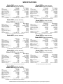
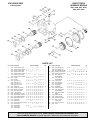
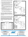
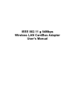
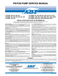
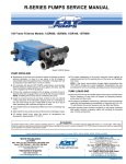
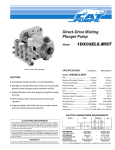
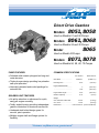
®
Direct Drive Gearbox
Models
8051, 8058
Used on Models 51 and 58 Pumps
Models
8061, 8068
Used on Models 34 and 35 Pumps
8065
Model
Used on Model 45 Pumps
Models
8071, 8078
Used on Models 56, 59, 60, 70 Pumps
PUMP FEATURES
●
COMMON SPECIFICATIONS
Polished solid ceramic plungers last long and
resist abrasion.
●
Triplex plunger design providing low pulsation
and quiet operation.
●
Internally lubricated and cooled packings for
extended life.
GEARBOX UNIT FEATURES
●
No pulley selection or adjustment for quick,
easy gas engine mounting.
●
Totally sealed housing providing independent
gearbox lubrication for maximum service life.
●
Hardened steel helical design gears for
smooth, quiet operation.
●
Multiple engine shaft and flange options for
flexibility.
U.S. Measure
Metric Measure
Gear Ratio ..............................
2.0384 to 1
(2.0384 to 1)
Mounting Face........................
6-1/2"
(165 mm)
Engine Shaft Diameter
...............................................
...............................................
1"
1-1/8"
(25.4 mm)
( 28.5 mm)
Engine Shaft Length...............
3-1/4"
(82.6 mm)
Gearbox Capacity...................
10 oz.
(0.30 L)
4.2 lbs.
7.5 lbs.
(1.90 kg)
(3.40 kg)
Weight
8051, 8058, 8061, 8065, 8068 ....
8071, 8078 ..............................
Dimensions............................. 6.42 x 4.53 x8.19" (163x115x208 mm)
“Customer confidence is our greatest asset”
SPECIFICATIONS
Model 34G1 [34 Pump, 8061 G.B.]
Model 34G118 [34 Pump, 8068 G.B.]
U.S. Measure
Metric Measure
Flow ........................................
4.0 GPM
(15 L/M)
Pressure Range .....................
100 to 2000 PSI
(7 to 140 BAR)
Inlet Pressure Range..............
Flooded to 60 PSI
(Flooded to 4 BAR)
Maximum Pump RPM.............
1725 RPM
(1725 RPM)
Maximum Engine RPM...........
3515 RPM
(3515 RPM)
Bore ........................................
0.787"
(20 mm)
★ Horsepower-Electric ...............
5.5 HP
(5.5 HP)
Stroke .....................................
0.394"
(10 mm)
Pump Crankcase Capacity .....
18 oz.
(0.55 L)
Weight ....................................
24.3 Ibs.
(11.0 kg)
Dimensions with G.B. .............
11.5 x 10.98 x 8.19"
(292 x 279 x 208 mm)
See Models 30, 31, 34, 35 data sheet for pump information.
Model 35G1 [35 Pump, 8061 G.B.]
Model 35G118 [35 Pump, 8068 G.B.]
U.S. Measure
Metric Measure
Flow ........................................
5.0 GPM
(19 L/M)
Pressure Range .....................
100 to 1500 PSI
(7 to 105 BAR)
Inlet Pressure Range..............
Flooded to 60 PSI
(Flooded to 4 BAR)
Maximum Pump RPM.............
1725 RPM
(1725 RPM)
Maximum Engine RPM...........
3515 RPM
(3515 RPM)
Bore ........................................
0.787"
(20 mm)
★Horsepower-Electric ...............
5.1 HP
(5.1 HP)
Stroke .....................................
0.472"
(12 mm)
Pump Crankcase Capacity .....
18 oz.
(0.55 L)
Weight ....................................
24.3 lbs.
(11.0 kg)
Dimensions with G.B. .............
11.5 x 10.98 x 8.19"
(292 x 279 x 208 mm)
See Models 30, 31, 34, 35 data sheet for pump information.
Model 45G1 [45 Pump, 8065 G.B.]
U.S. Measure
Metric Measure
Flow ........................................
4.5 GPM
(17 L/M)
Pressure Range .....................
100 to 3500 PSI
(7 to 245 BAR)
Inlet Pressure Range..............
Flooded to 60 PSI
(Flooded to 4 BAR)
Maximum Pump RPM.............
1645 RPM
(1645 RPM)
Maximum Engine RPM...........
3353 RPM
(3353 RPM)
Bore ........................................
0.630"
(16 mm)
★Horsepower-Electric ...............
10.8 HP
(10.8 HP)
Stroke .....................................
0.708"
(18 mm)
Pump Crankcase Capacity .....
18 oz.
(0.55 L)
Weight ....................................
25.3 lbs.
(11.5 kg)
Dimensions with G.B. .............
12.0 x 10.98 x 5.5"
(345 x 279 139 mm)
See Model 45 data sheet for pump information.
Model 51G1 [51 Pump, 8051 G.B.]
Model 51G118 [51 Pump, 8058 G.B.]
U.S. Measure
Metric Measure
Flow ........................................
4.8 GPM
(18 L/M)
Pressure Range .....................
100 to 3000 PSI
(7 to 210 BAR)
Inlet Pressure Range..............
Flooded to 60 PSI
(Flooded to 4 BAR)
Maximum Pump RPM.............
1765 RPM
(1765 RPM)
Maximum Engine RPM...........
3600 RPM
(3600 RPM)
Bore ........................................
0.630"
(16 mm)
★ Horsepower-Electric ...............
9.8 HP
(9.8 HP)
Stroke .....................................
0.728"
(18.5 mm)
Pump Crankcase Capacity .....
25 oz.
(0.75 L)
Weight ....................................
30.7 lbs.
(13.9 kg)
Dimensions with G.B. .............
13.58 x 10.75 x 8.19"
(345 x 273 x 208 mm)
See Models 53, 58, 55, 51 data sheet for pump information.
Model 58G1 [58 Pump, 8051 G.B.]
Model 58G118 [58 Pump, 8058 G.B.]
U.S. Measure
Metric Measure
Flow ........................................
5.0 GPM
(19 L/M)
Pressure Range .....................
100 to 2500 PSI
(7 to 175 BAR)
Inlet Pressure Range..............
Flooded to 60 PSI
(Flooded to 4 BAR)
Maximum Pump RPM.............
1570 RPM
(1570 RPM)
Maximum Engine RPM...........
3200 RPM
(3200 RPM)
Bore ........................................
0.708"
(18 mm)
★ Horsepower-Electric ...............
8.6 HP
(8.6 HP)
Stroke .....................................
0.669"
(17 mm)
Pump Crankcase Capacity .....
25 oz.
(0.75 L)
Weight ....................................
30.7 lbs.
(13.9 kg)
Dimensions with .B. ................
13.58 x 10.75 x 8.19"
(345 x 273 x 208 mm)
See Models 53, 58, 55, 51 data sheet for pump information.
Model 59G1 [59 Pump, 8071 G.B.]
Model 59G118 [59 Pump, 8078 G.B.]
U.S. Measure
Metric Measure
Flow ........................................
5.5 GPM
(21 L/M)
Pressure Range .....................
100 to 3500 PSI
(7 to 245 BAR)
Inlet Pressure Range..............
Flooded to 60 PSI
(Flooded to 4 BAR)
Maximum Pump RPM.............
1570 RPM
(1570 RPM)
Maximum Engine RPM...........
3200 RPM
(3200 RPM)
Bore ........................................
0.708"
(18 mm)
★Horsepower-Electric ...............
13.2 HP
(13.2 HP)
Stroke .....................................
0.728"
(18.5 mm)
Pump Crankcase Capacity .....
25 oz.
(0.75 L)
Weight ....................................
36.8 lbs.
(16.7 kg)
Dimensions with G.B. .............
13.9 x 10.75 x 8.19"
(353 x 273 x 208 mm)
See Models 56, 57, 59, 60 data sheet for information.
Model 60G1 [60 Pump, 8071 G.B.]
Model 60G118 [60 Pump, 8078 G.B.]
U.S. Measure
Metric Measure
Flow ........................................
4.5 GPM
(17 L/M)
Pressure Range .....................
100 to 4000 PSI
(7 to 275 BAR)
Inlet Pressure Range..............
Flooded to 60 PSI
(Flooded to 4 BAR)
Maximum Pump RPM.............
1570 RPM
(1570 RPM)
Maximum Engine RPM...........
3200 RPM
(3200 RPM)
Bore ........................................
0.708"
(18 mm)
★Horsepower-Electric ...............
12.3 HP
(12.3 HP)
Stroke .....................................
0.591"
(15 mm)
Pump Crankcase Capacity .....
25 oz.
(0.75 L)
Weight ....................................
36.8 lbs.
(16.7 kg)
Dimensions with G.B. .............
13.9 x 10.75 x 8.19"
(353 x 273 x 208 mm)
See Models 56, 57, 59, 60 data sheet for pump information.
Model 70G1 [70 Pump, 8071 G.B.]
Model 70G118 [70 Pump, 8078 G.B.]
U.S. Measure
Metric Measure
Flow ........................................
4.5 GPM
(17 L/M)
Pressure Range .....................
100 to 5000 PSI
(7 to 345 BAR)
Inlet Pressure Range..............
Flooded to 60 PSI
(Flooded to 4 BAR)
Maximum Pump RPM.............
1700 RPM
(1700 RPM)
Maximum Engine RPM...........
3465 RPM
(3465 RPM)
Bore ........................................
0.551"
(14 mm)
★Horsepower-Electric ...............
15.4 HP
(15.4 HP)
Stroke .....................................
0.945"
(24 mm)
Pump Crankcase Capacity .....
25 oz.
(0.75 L)
Weight ....................................
43.6 lbs.
(19.8 kg)
Dimensions with G.B. .............
14.02 x 10.75 x 8.19"
(356 x 273 x 208 mm)
See Model 70 data sheet for pump information.
Model 56G1 [56 Pump, 8071 G.B.]
Model 56G118 [56 Pump, 8078 G.B.]
U.S. Measure
Metric Measure
Flow ........................................
8.0 GPM
(30 L/M)
Pressure Range .....................
100 to 1800 PSI
(7 to 125 BAR)
Inlet Pressure Range..............
Flooded to 60 PSI
(Flooded to 4 BAR)
Maximum Pump RPM.............
1760 RPM
(1760 RPM)
Maximum Engine RPM...........
3600 RPM
(3600 RPM)
Bore ........................................
0.708"
(18 mm)
★ Horsepower-Electric ...............
9.9 HP
(9.9 HP)
Stroke .....................................
0.945"
(24 mm)
Pump Crankcase Capacity .....
25 oz.
(0.75 L)
Weight ....................................
36.8 lbs.
(16.7 kg)
Dimensions with G.B. .............
13.9 x 10.75 x 18.9"
(353 x 273 x 208 mm)
See Models 56, 57, 59, 60 data sheet for pump information.
★Standard Electric Brake Horsepower Requirement provided. Consult Gas Engine Mfr. for gas horsepower equivalent.
EXPLODED VIEW
DIRECT DRIVE
GEARBOX MODELS
February 2005
8051, 8058, 8061, 8065,
8068, 8071, 8078
PARTS LIST
Item
—
—
—
—
—
—
—
502
503
504
505
506
507
508
509
510
511
512
513
514
515
516
Part No. Description
8051
8058
8061
8065
8068
8071
8078
44673
45351
44675
45352
44690
45358
56110
55459
146423
44676
23170
25625
44428
92241
103685
44374
20129
44679
45744
45745
45759
46121
Gearbox, Helical (1" Shaft)
Gearbox, Helical (1-1/8" Shaft)
Gearbox, Helical (1" Shaft)
Gearbox, Helical (1" Shaft)
Gearbox, Helical (1-1/8" Shaft)
Gearbox, Helical (1" Shaft)
Gearbox, Helical (1-1/8" Shaft)
Housing
Housing
Gear, Pinion (1")
Gear, Pinion (1")
Gear, Pinion (1-1/8")
Gear, Pinion (1-1/8")
Bearing, Ball
Retainer, Ring (External)
Retainer, Ring (Internal)
Seal, Oil Case, Pinion
O-Ring, Drain Plug
Plug, Oil Drain (1/4"-19 BSP)
Gasket, Flat Flex, Oil Gauge
Gauge, Bubble Oil w/Gasket
Gasket, Flat Flex, Oil Cap
Cap, Oil Filler
Washer (M20)
Seal, Oil, Bearing Cover Flange
Gasket, Flange
Gasket, Flange
Gasket, Flange
Gasket, Flange
Gearbox Pump Model
—
—
34
—
34
—
—
34
—
34
—
34
—
34
34
34
34
34
34
34
34
34
34
—
34
—
34
—
—
—
—
35
—
35
—
—
35
—
35
—
35
—
35
35
35
35
35
35
35
35
35
35
—
35
—
35
—
—
—
—
—
45
—
—
—
45
—
45
—
—
—
45
45
45
45
45
45
45
45
45
45
45
45
—
—
—
45
51
51
—
—
—
—
—
51
—
51
—
51
—
51
51
51
51
51
51
51
51
51
51
—
51
51
—
—
—
—
—
—
—
—
56
56
—
56
—
56
—
56
56
56
56
56
56
56
56
56
56
56
—
56
—
—
56
—
58
58
—
—
—
—
—
58
—
58
—
58
—
58
58
58
58
58
58
58
58
58
58
—
58
58
—
—
—
—
—
—
—
—
59
59
—
59
—
59
—
59
59
59
59
59
59
59
59
59
59
59
—
59
—
—
59
—
—
—
—
—
—
60
60
—
60
—
60
—
60
60
60
60
60
60
60
60
60
60
60
—
60
—
—
60
—
—
—
—
—
—
70
70
—
70
—
70
—
70
70
70
70
70
70
70
70
70
70
70
—
70
—
—
70
—
Qty.
Item
1
1
1
1
1
1
1
1
1
1
1
1
1
1/2
1
1
1
1
1
1
1
1
1
1
1
1
1
1
1
517
518
519
Part No. Description
45933
45934
46122
210619
46123
45763
46124
520
521
523
524
14045
44680
44711
44459
101814
26118
92521
525
92530
526
528
529
530
12489
12490
12503
34100
531
532
44455
34042
522
Flange, Bearing Cover
Flange, Bearing Cover
Flange, Bearing Cover (M8)
Lockwasher, Conical (M6)
Lockwasher, Conical (M8)
Screw, Hex Socket
Flat Head (M6x16)
Screw, Hex Socket
Flat Head (M8x16)
O-Ring, Flange
Gear, Helical Drive
Gear, Helical Drive
Key (M8x7x24)
Key (M6x6x27)
Washer, Flat Holding
Screw, Sems Hex Head
Retaining (M8x20)
Screw, Sems Hex Head
(M8x25)
Washer, Flat (M8)
Washer, Flat (M10)
Lockwasher, Split (M10)
Screw, Hex Head
(3/8-16x1-3/8")
Key (1/4"x1/4"x2-5/32")
Spacer
Gearbox Pump Model
Qty.
34
—
—
34
—
34
35
—
—
35
—
35
—
—
45
—
45
—
1
1
1
4/8
4
4/8
—
—
45 —
—
—
—
4
34
—
34
—
34
34
34
35
—
35
—
35
35
35
45
—
45
—
45
45
45
51
51
—
51
—
51
51
56
56
—
56
—
56
56
58 59 60 70
58 59 60 70
— — — —
58 59 60 70
— — — —
58 59 60 70
58 59 60 70
1
1
1
1
1
1
1
34
35
45 51
56
58
59 60
70
4
34
34
34
34
35
35
35
35
45
45
45
45
51
51
51
51
56
56
56
56
58
58
58
58
59
59
59
59
60
60
60
60
70
70
70
70
4
4
4
4
34
34
35
35
45 51
45 51
56
56
58
58
59 60
59 60
70
70
1
4
— — — — — —
51 — 58 59 60 70
— — — — — —
51 56 58 59 60 70
— — — — — —
51 56 58 59 60 70
Before you begin servicing your pump, Please carefully read OPERATOR’S MANUAL and
separate SERVICE MANUAL for special lubrication, disassembly and reassembly information.
—
—
SERVICING THE GEARBOX
DISASSEMBLY
1. Completely drain lube from gearbox housing.
2. Remove the four HHC screws which fasten the gearbox
to the engine and separate gearbox and pump from
engine.
3. Remove the four HHC screws which fasten the gearbox
to the bearing cover flange and separate gearbox housing from pump.
4. Place gearbox housing on work surface with seal
facing up.
5. Remove pinion oil seal by inserting screwdriver between
pinion gear and inner lip of seal and pry out. Seal will be
damaged and must be replaced.
6. Remove large retaining ring in groove below the pinion oil
seal using retaining ring pliers and set aside for re-use.
7. Remove the pinion gear and bearing. Turn gearbox
housing over onto engine mount flange surface.
Bearing is pressed into position so it is necessary to
press pinion and bearing out from rear. Set gearbox
housing aside.
8. Remove bearing from pinion gear. Using reverse pliers
remove retaining ring from groove on pinion gear and
press bearing from pinion. Set aside pinion, bearing and
retaining ring.
9. Remove hex machined retaining screw, lockwasher and
flat holding washer from center of helical drive gear on
pump shaft.
10. Slip helical drive gear from crankshaft.
11. Remove key from keyway in pump crankshaft.
At this point the gearbox has been disassembled. Now
begin examination of the gearbox parts for wear and
reassembly.
While the gearbox is in this state of disassembly, it
is advisable to examine your pump for any indication
of drive-end wear.
If any of the following conditions are present, removal
of the bearing cover flange is necessary. Only
trained technicians should service drive end.
●
●
●
Leakage between bearing cover flange and pump
crankcase.
Evidence of water in pump crankcase.
Evidence of water in gearbox crankcase.
NOTE: If removal of bearing cover flange is necessary,
completely drain oil from crankcase of pump.
REMOVING BEARING COVER FLANGE
1. Remove the HSH screws, lockwashers and washers
from bearing cover flange.
2. Tap flange with soft mallet to separate from pump
crankcase.
3. Examine pump bearing and replace if worn.
4. Examine oil seal in bearing cover flange and replace if
worn.
5. Examine gasket on outside of bearing cover flange and
replace if cut or cracked.
6. Examine o-ring on inside outer groove of bearing cover
flange and replace if cut or worn.
If further pump servicing is needed, refer to your pump
service manual, and Tech Bulletin 035 on “Servicing
Crankcase Section”.
REPLACING BEARING COVER FLANGE
1. Line up the four holes and mount gasket on outside of
bearing cover flange. Note: Models 56, 59, 60 and 70
have dual bearings and eight screws.
2. Press new seal into bearing cover flange after exercising
caution not to cut seal on keyway edge.
3. Line up the inside mounting holes on bearing cover
flange with the holes on the pump. Keep the two outer
“flanged” mounting holes to the top rear and lower
front.
4. Apply Loctite-242 to the threaded area of screws before
replacing. Torque per chart.
REASSEMBLY
1. Insert key into pump crankshaft keyway until flush with
end of shaft.
2. Examine helical drive gear teeth for wear and replace if
necessary. Line up keyway on gear with pump shaft keyway and key and slide onto shaft.
3. Install flat holding washer, lockwasher and retaining
screw onto shaft and torque per chart.
4. Examine gearbox oil gauge and oil drain plug for any
evidence of leaking and replace o-ring and gasket if
necessary.
5. Examine pinion bearing for wear and replace if necessary.
6. Examine pinion gear teeth for wear and replace if
necessary.
7. Press bearing over pinion gear until seated on shoulder.
(Models with dual bearings; press first bearing on until
seated; then second bearing until seated up to first
bearing.)
8. Install retaining ring on pinion gear and snap into
groove.
9. Insert pinion and gear assembly into gearbox housing
and press into position until seated on shoulder. Groove
for large retaining ring must be visible.
10. Insert large retaining ring into pinion bearing housing and
snap into groove.
11. Lubricate I.D. and O.D. of new pinion oil seal. Place oil
seal at mouth of pinion bearing housing with garter
spring facing down. Carefully press seal into position
until seated on retaining ring. Keep seal square in position to avoid inner lip hanging up on pinion gear edge.
12. Rotate pinion gear so keyway is up. Mount assembled
gearbox housing onto pump shaft with helical drive gear.
NOTE: Carefully match gear teeth and line up mounting
holes. Place engine mounting flange in forward
position.
13. Install the screws to fasten gearbox to bearing cover
flange. Torque per chart.
MOUNTING PUMP WITH GEARBOX ONTO ENGINE
DIMENSIONAL
1. Rotate crankshaft of engine until keyway is at top.
2. Insert key into keyway and generously apply Loctite
76764 antiseize lubricant to engine shaft.
3. Line up keyway of pinion gear and engine shaft and
carefully slip gearbox onto engine shaft until flush with
engine face. Install four hex machined screws. Torque
per chart.
NOTE: Due to varying engine shaft lengths it may be
necessary to install a small spacer on each of the four
(4) hex machined screws between gearbox flange
and engine face.
4. Before starting operation, fill gearbox housing to oil
gauge dot with 80-90 weight gear lube and fill
crankcase of pump to oil gauge dot with CAT PUMPS
Special Premium Grade Non-detergent Oil.
FIELD CONVERSION FROM STANDARD PUMP
To convert from a standard pump to a gearbox pump,
remove the existing bearing cover, gasket and four combination head screws. Replace with new gearbox bearing
cover flange, gasket, four lockwashers and new hex socket
flat head screws.
Models
34G1, 34G118,
35G1, 35G118
45G1
DIMENSIONAL
The bearing for the 51, 56, 58, 59 and 60 pumps is a tapered
roller bearing with outer race. Remove the standard bearing
cover from the pump. Remove outer race from bearing cover
by gently pounding on work surface to unseat. Then use a
bearing puller tool to pull race from bearing cover. Next
press outer race into gearbox bearing cover flange. Be
certain race is completely seated in flange before mounting
onto pump.
TORQUE CHART
Description
Gearbox Housing to
Bearing Cover Flange
Thread
M8
Tool
13 mm
Torque
70 in. lbs.
(8 Nm)
Bearing Cover Flange to
Pump (M6)
M6
4 mm
70 in. lbs.
(8 Nm)
Bearing Cover Flange to
Pump (M8)
M8
5 mm
125 in. lbs.
(15 Nm)
Drive Gear
Retaining Screw
M8
13 mm
110 in. lbs.
(12 Nm)
Engine Mounting
Screw
3/8-16
14 mm
110 in. lbs.
(12 Nm)
Models
51G1, 51G118
56G1, 56G118
58G1, 58G118
59G1, 59G118
60G1, 60G118
70G1, 70G118
CAT PUMPS (U.K.) LTD.
World Headquarters
CAT PUMPS
1681 - 94th Lane N.E. Minneapolis, MN 55449 - 4324
Phone (763) 780-5440 — FAX (763) 780-2958
e-mail: [email protected]
www.catpumps.com
International Inquiries
FAX (763) 785-4329
e-mail: [email protected]
1 Fleet Business Park, Sandy Lane, Church Crookham, Fleet
Hampshire GU52 8BF, England
Phone Fleet 44 1252-622031 — Fax 44 1252-626655
e-mail: [email protected]
The Pumps with Nine Lives
N.V. CAT PUMPS INTERNATIONAL S. A.
Heiveldekens 6A, 2550 Kontich, Belgium
Phone 32- 3- 450.71.50 — Fax 32-3- 450.71.51
e-mail: [email protected] www.catpumps.be
CAT PUMPS DEUTSCHLAND GmbH
Buchwiese 2, D-65510 Idstein, Germany
Phone 49 6126-9303 0 — Fax 49 6126-9303 33
e-mail: [email protected] www.catpumps.de
PN 993152 Rev A 1517