1
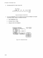
HP 16510A
LOGIC ANALYSIS MODULE
Service Manual
Flin-
HEWLETT
~~ PACKARD
r/inHEWLETT
~e..I PACKARD
SERVICE MANUAL
HP 16510A 25 MHz State/
1 00 MHz Timing Card
© COPYRIGHT I1EWLETT-PACKARD COMPANY/COLORADO DIVISION 1987
1900 GARDEN OF THE GODS ROAD, COLORADO SPRINGS, COLORADO U.S.A.
ALL RIGHTS RESERVED
Manual Part No. 16510-90901
Microfiche Part No. 16510-90801
PRINTED: SEPTEMBER 1987
CERTIFICATION
Hewlett-Packard Company certifies that this product met its published specifications at the time of
shipment from the factory. Hewlett-Packard further certifies that its calibration measurements are
traceable to the United States National Bureau of Standards, to the extent aI/owed by the Bureau's
calibration facility, and to the calibration facilities of other International Standards Organization
members.
WARRANTY
This Hewlett-Packard product is warranted against defects in material and workmanship for a
period of one year from date of shipment. During the warranty period, Hewlett-Packard Company
will, at its option, either repair or replace products which prove to be defective.
For warranty service or repair, this product must be returned to a service facility designated by HP.
Buyer shall prepay shipping charges to HP and HP shall pay shipping charges to return the
product to Buyer. However, Buyer shall pay all shipping charges, duties, and taxes for products
returned to HP from another country.
HP warrants that its software and firr:nware deSignated by HP for use with an instrument will
execute its programming instructions when properly installed on that instrument. HP does not
warrant that the operation of the instrument or software, or firmware will be uninterrupted or error
free.
LIMITATION OF WARRANTY
The foregoing warranty shall not apply to defects resulting from improper or inadequate
maintenance by Buyer, buyer··supplied software or interfacing, unauthorized modification or
misuse, operation outside the environmental specifications for the product, or improper site
preparation or maintenance.
NO OTHER WARRANTY IS EXPRESSED OR IMPLIED. HP SPECIFICALLY DISCLAIMS THE
IMPLIED WARRANTIES OF MERCHANTABILITY AND FITNESS FOR A PARTICULAR PURPOSE.
EXCLUSIVE REMEDIES
THE REMEDIES PROVIDED HEREIN ARE BUYER'S SOLE AND EXCLUSIVE REMEDIES. HP
SHALL NOT BE LIABLE FOR ANY DIRECT, INDIRECT, SPECIAL, INCIDENTAL, OR
CONSEQUENTIAL DAMAGES, WHETHER BASED ON CONTRACT, TORT, OR ANY OTHER LEGAL
THEORY.
ASSISTANCE
Product maintenance agreements and other customer assistance agreements are available for
Hewlett-Packard products.
For any assistance, contact your nearest Hewlett-Packard Sales and Service Office. Addresses are
provided at the back of tllis manual.
CWA584
SAFETY CONSIDERATIONS
GENERAL • This Is a Safety Class I Instrument (provided
o Do not Install substitute parts or perform any unauthorized
with terminal for protective earthing).
modification to the Instrument.
OPERATION· BEFORE APPLYING POWER verify that the
o Adjustments described In the manual are performed with
power transformer primary Is matched to the available line
voltage, the correct fuse Is Installed, and Safety Precautions
are taken (see the following warnings)., In addition, note the
power supplied ~o the Instrument while protective covers
are removed. Energy available at many pOints may, If
contacted, result In personal injury.
instrument's external markings which are described under
"Safety Symbols."
o Any adjustment, maintenance, and repair of the opened
Instrument under voltage should be avoided as much as
I
WARNING
I
possible, and when inevitable, should be carried out only by
a skilled person who Is aware of the hazard Involved.
o Servicing Instructions are for use by service-trained
personnel. To avoid dangerous electric shock, do not
o Capacitors Inside the Instrument may stili be charged even
If the Instrument has been disconnected from Its source of
perform any servicing unless qualified to do so.
o BEFORE
SWITCHING
ON
THE
supply.
INSTRUMENT,
the
protective earth terminal of the Instrument must be
connected to the protective conductor of the (mains)
powercord.
SAFETY SYMBOLS
The mains plug shall only be Inserted In a
&
socket outlet provided with a protective earth contact. The
protective action must not be negated by the use of an
extension
cord
(power
cable)
without
a
protective
conductor (grounding). Grounding one conductor of a two-
Instruction manual symbol. The product will be
marked with this symbol when It Is necessary for
the user to refer to the Instruction manual In order
to protect against damage to the product.
conductor outlet Is not sufficient protection.
o If
this
Instrument
Is
to
be
energized
via
an
Indicates hazardous voltages.
auto-transformer (for voltage reduction) make sure the
common terminal Is connected to the earth terminal of the
-L
power source.
o Any Interruption of the protective (grounding) conductor
Earth terminal (sometimes used In manual to
Indicate circuit common connected to grounded
chassis).
(Inside or outside the Instrument) or disconnecting the
protective earth terminal will cause a potential shock
hazard that could result In personal InJury.
o Whenever It Is likely that the protection has been Impaired,
the Instrument must be made inoperative and be secured
against any unintended operation.
I
WARNING
I
The WARNING sign denotes a hazard. It
calls attention to a procedure, practice,
or the like, which, If not correctly
performed or adhered to, could result In personal Injury. Do
not proceed beyond a WARNING sign until the Indicated
conditions are fully understood and met.
o Only fuses with the required rated current, voltage, and
speCified type (normal blow, time delay, etc.) should be
used.
Do not use repaired fuses or short circuited
fuseholders. To do so could cause a shock or fire hazard.
'~
The CAUTION sign denotes a hazard. It
calls attention to an operating procedure,
practice,
or
the
like,
which,
If
not
correctly performed or adhered to, could result In damage to
o Do not operate the Instrument In th~ presence of flammable
gasses or fumes. Operation of any electrical Instrument in
such an environment constitutes a definite safety hazard.
or destruction of part or all of the product. Do not proceed
beyond a CAUTION sign until the Indicated conditions are
fully understood or met.
SC10984
HP 1651 OA - Table of Contents
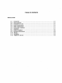
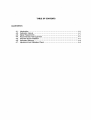
TABLE OF CONTENTS
SECTION
PAGE
I. GENERAL INFORMATION ........................................................................ 1-1
1-1.
1-2.
1-3.
1-4.
1-5.
1-6.
1-7.
1-8.
1-9.
Introduction .......•..............................................................•....
Modules Covered By Manual .........................................................
Safety Requirements •.................................................................
Product Description ..............................................................•....
Accessories Supplied .................................................................
Accessories Available ..............•..•....•..........•..............................•
Specifications .....................................................................•...
Operating Characteristics .............................................................
Recommended Test Equipment ......................................................
1-1
1-1
1-1
1-2
1-2
1-2
1-2
1-2
1-2
II. INSTALLATION .................................................•................................. 2-1
2-1.
2-2.
2-3.
2-4.
2-5.
2-6.
2-7.
Introduction ........................................................................... 2-1
Initial Inspection .....................................................................•. 2-1
Preparation For Use .................................................................. 2-1
Power Requirements ................................................................. 2-1
Safety Requirements .................................................................. 2-1
Probe Cable Installation .............................................................. 2-1
Installation ............................................................................. 2-1
2-8. Module Installation .................................................................... 2-2
2-9. Operating Environment ............................................................... 2-4
2-10. Storage ...•........................................................................... 2-4
2-11. Packaging ............................................................................ 2-4
2-12. Tagging For Service .................................................................. 2-4
III. PERFORMANCE TESTS ......................................................................... 3-1
3-1.
3-2.
3-3.
3-4.
3-5.
3-6.
3-7.
3-8.
3-9.
3-10.
3-11.
3-12.
3-13.
3-14.
3-15.
3-16.
3-17.
iv
Introduction ........................................................................... 3-1
Recommended Test Equipment ...................................................... 3-1
Test Record ........................................................................... 3-1
Performance Test Interval ............................................................ 3-1
Performance Test Procedures ........................................................ 3-1
Test Connector ........................................................................ 3-1
Clock, Qualifier, and Data Input Tests ................................................ 3-2
Clock, Qualifier, and Data Input Tests 1 ............................................. 3-2
Clock, Qualifier, and Data Input Tests 2 ............................................. 3-6
Clock, Qualifier, and Data Input Tests 3 ............................................. 3-9
Clock, Qualifier, and Data Input Tests 4 ........................................... 3-12
Clock, Qualifier, and Data Input Tests 5 ........................................... 3-16
Clock, Qualifier, and Data Input Tests 6 ........................................... 3-19
Clocl<, Qualifier, and Data Input Tests 7 ........................................... 3-22
Glitch Test ........................................................................... 3-25
Threshold Accuracy Test ........................................................... 3-30
Dynamic Range Test ............................................................... 3-37
HP 16510A - Table of Contents
TABLE OF CONTENTS
SECTION
PAGE
IV. ADJUSTMENTS .................................................................................. 4-1
4-1.
4-2.
4-3.
4-4.
4-5.
4-6.
4-7.
Introduction ........................................................................... 4-1
Calibration Interval .................................................................... 4-1
Safety Requirements .................................................................. 4-1
Recommended Test Equipment ...................................................... 4-1
Extender Board Installation ........................................................... 4-1
Instrument Warmup ................................................................... 4-4
Adjustment And Calibration Check ................................................... 4-4
V. REPLACEABLE PARTS .......................................................................... 5-1
5-1.
5-2.
5-3.
5-4.
5-5.
5-6.
Introduction ............................................................................
Abbreviations ..........................................................................
Replaceable Parts List ................................................................
Ordering Information ........•.........................................................
Exchange Assemblies ................................................................
Direct Mail order System .............................................................
5-1
5-1
5-1
5-1
5,::1
5:-2
VI. SERViCE .......................................................................................... 6-1
6-1.
6-2.
6-3.
6-4.
6-5.
6-6.
6-7.
6-8.
Introduction ........................................................................... 6~1
Safety Requirements .................................................................. 6,'71
Recommended Test Equipment ...................................................... 6~ 1
Module Block Diagram and Theory Of Operation ................................... 6-1
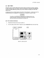
Self Tests .............................................................................. 6-3
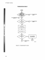
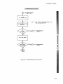
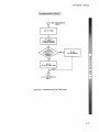
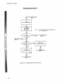
Troubleshooting ....................................................................... 6-7
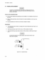
Module Replacement ............................................................... 6-14
Probe Cable Replacement .......................................................... 6-17
v
HP 16510A - Table of Contents
LIST OF TABLES
TABLE
PAGE
TITLE
1-1. HP 1651 OA Specifications .................................................................... 1-3
1-2. HP 1651 OA Operating Characteristics ........................................................ 1-4
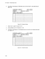
1-3. Recommended Test Equipment .............................................................. 1-12
3-1. Performance Test Record ........................................................•...•...•... 3-42
5-1. Reference Designators and Abbreviations .................................................... 5-3
5-2. Replaceable Parts ... . . . . . . . . . . . . . . . . . . . . . . . . . . . . . . . . . . . . . . . . . . . . . . . . . . . . . . . . . . . . . . . . . . . . . . . . .. 5-4
LIST OF ILLUSTRATIONS
FIGURE
TITLE
PAGE
2-1 . Endplate Overlap .............................................................................. 2-2
2-2. Cable Position ................................................................................. 2-3
2-3. Endplate Overlap .............................................................................. 2-3
3-1.
3-2.
3-3.
3-4.
3-5.
3-6.
3-7.
3-8.
3-9.
3-10.
3-11.
3-12.
3-13.
3-14.
3-15.
3-16.
3-17.
3-18.
3-19.
3-20.
3-21.
3-22.
3-23.
3-24.
3-25.
3-26.
3-27.
3-28.
3-29.
3-30.
vi
Test Connector ................................................................................ 3-1
Setup for Clock, Qualifier, and Data Inputs Test 1 ........................................... 3-2
Waveform for Clock, Qualifier, and Data Inputs Test 1 ...................................... 3-3
Configuration Screen ......................................................................... 3-3
Format Screen ................................................................................ 3-4
Trace Screen ......................................................... : ........................ 3-4
Listing Screen ................................................................................. 3-5
Setup for Clock, Qualifier, and Data Inputs Test 2 ........................................... 3-6
Waveform for Clock, Qualifier, and Data Inputs Test 2 ...................................... 3-7
Trace Screen ................................................................................. 3-7
Listing Screen ................................................................................ 3-8
Setup for Clock, Qualifier, and Data Inputs Test 3 .......................................... 3-9
Waveforms for Clock, Qualifier, and Data Inputs Test 3 ................................... 3-10
Listing Screen ............................................................................... 3-10
Setup for Clock, Qualifier, and Data Inputs Test 4 ......................................... 3-12
Waveforms for Clock, Qualifier, and Data Inputs Test 4 ................................... 3-13
Configuration Screen ........................................................................ 3-13
Format Screen ............................................................................... 3-14
Trace Screen ............. -................................................................... 3-14
Listing Screen ............................................................................... 3-15
Setup for Clock, Qualifier, and Data Inputs Test 5 ......................................... 3-16
Waveforms for Clock, Qualifier, and Data Inputs Test 5 ................................... 3-17
Listing Screen ............................................................................... 3-17
Setup for Clock, Qualifier, and Data Inputs Test 6 ......................................... 3-19
Waveforms for Clock, Qualifier, and Data Inputs Test 6 ................................... 3-20
Format Screen ............................................................................... 3-20
Listing Screen ............................................................................... 3-21
Setup for Clock, Qualifier, and Data Inputs Test 7 ......................................... 3-22
Waveforms for Clock, Qualifier, and Data Inputs Test 7 ................................... 2-23
Format Screen ............................................................................... 3-23
HP 16510A - Table of Contents
LIST OF ILLUSTRATIONS
FIGURE
3-31.
3-32.
3-33.
3-34.
3-35.
3-36.
3-37.
3-38.
3-39.
3-40~
3-41.
3-42.
3-43.
3-44.
3-45.
3-46.
3-47.
3-48.
3-49.
3-50.
3-51.
PAGE
TITLE
Listing Screen ............................................................................... 3-24
Setup for Glitch Test ........................................................................ 3-25
Waveform for Glitch Test .................................................................... 3-26
Configuration Screen ........................................................................ 3-26
Format Screen ............................................................................... 3-27
Trace Screen .................•.............................................................. 3-28
Timing Screen ............................................................................... 3-29
Setup for Threshold Accuracy Test ......................................................... 3-30
Configuration Screen ........................................................................ 3-31
Format Screen ............................................................................... 3-32
Trace Screen ................................................................................ 3-33
Waveform Screen .............•.............................
3-34
Waveform Screen ..
3-34
3-35
Format Screen .....
Format Screen ..........................
3-36
Setup for Dynamic Range Test ............................................................. 3-37
3-38
Configuration Screen ......
Format Screen ......
3-38
3-39
Trace Screen
3-40
Waveform Screen ............
3-40
Waveform Screen .........
0
0.
0
0
0
••••••••••
••••••••
0
•
0
0
•••••••••••••••••••••••
••••••••••••••••••••••••••
0
0
0
•••••
0
0
••••
0
••••••
0
••••••
0
0
•••••••••••
•••••••••••
0
•
0
0
•••
0
••
0
••••••••••••••••••••••
••••••••
0
0
0
•••••
0
•••••••
0
•••••
••••••••••••••••
••••••••••••••••••••
0
•••••••••••••••••••••••••••••••••••
0
•••••
0
•••••
0
0
••••
•
0
•
0
•••••••••
0
••••••••
•••••••••••••••••
0
0
•••••••••••••••
0
•••
0
0
•
0
0
••••••••••
0
0
0
•••
••••
0
0
0
•••••
•
0
.00
••••
0
•
••••••••••••••••••••••••
•••••••••••••••••••
0
0
••••••••••••
0
0
••••••••••
•••••••••••
00
0
0
0"
0
••
0
.0.
••••••••••••••••
00
:
•••
•••••••
•
••
0
0
•••••••••••••••••
0
•
0
••
0
0
•••
0
•••
0
0
••
•••
•••••••••••
•••••••••••••••••
4-1. Endplate Overlap .....................................
4-1. _Extended Board and Module .................................................................
4-3. Adjustment Pot Location ......................................................................
4-4. Startup Screen ......
4-5. Pod Threshold Field .................................... . . . . . . . . . . . . . . . . . . . . . . . . . . . . . . . . . . . . ..
0
6-1.
6-2.
6-3.
6-4.
6-5.
6-6.
6-7.
6-8.
6-9.
6-10.
6-11.
6-12.
6-13.
6-14.
6-15.
6-16.
•
•
•
•
•
•
•
•
•
•
•
•
•
•
•
•
•
•
•
•
•
•
•
•
•
•
•
•
•
•
•
•
0
••••••••••••••••••
0
•
•
•
•
•
•
•
•
•
•
•
•
•
•
•
•
•
•
•
••
•
•
•
•
•
•
•
•
•
•
•
•
•
•
•
•
•
•
•
•
•
•
••
•
•
•
•
•
•
•
•
•
•
•
•
•
•
•
•
•
4-2
4-3
4-'4
4''::5
4':'5
HP 16510A State/Timing Analyzer Block Diagram ........................................... 6-1
Startup Screen ......
6-3
Load Test System ...
6-4
Test System Screen ........................................................................... 6-4
~
6-5
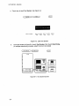
Main Test menu .....
Chip 1 Tests Run Screen ................................................ '.' ................... 6-5
stop Field ............. ~ . . . . . . . . . . . . . . . . . . . . . . . . . . . . . . . . . . . . . . . . . . . . . . . . . . . . . . . . . . . . . . . . . . . . . .. 6-6
Exit Test System .............................................................................. 6-6
Troubleshooting Flow Chart .................................................................. 6-8
Endplate Overhang .............................................................. ; ........... 6-14
Cable Position ............................................................................... 6-1 5
Endplate Overhang .......................................................................... 6-16
Endplate Overhang .......................................................................... 6-17
Card On Antistatic Mat ...................................................................... 6-18
Retainer And Screws ........................................................................ 6-18
Card Connectors .............................................................
6-19
0
•
0
•••••••••••••••••••••••••••••••••••••••••••••••••••••••••••••••••••••••••
•
•
•
•
•
•
•
•
•
•
•
•
•
•
•
•
•
•
•
•
•
•
•
•
•
•
•
•
•
•
•
•
•
•
•
•
•
•
•
•
•
•
•
•
•
•
•
•
•
•
•
•
•
•
•
•
0
•••••••••••••••••••••••••••••••••••••••••••••••••••••••
•
•
•
•
•
•
•
•
•
•
•
•
•
•
•
•
•
•
•
•
•
•
•
•
•
•
•
•
•
••
••
o ••••••••••••••
vii
TABLE OF CONTENTS
GENERAL INFORMATION
1.1.
1-2.
1-3.
1-4.
1-5.
1-6.
1-7.
1-8.
1-9.
Introduction ............................................................................
Modules Covered By Manual .......... a. • • • • • • • •• • • • • • • • • • • • • • • • • • • • • • • • • • • • • • • • • • • • ••
Safety Requirements ...................................................................
Product Description ....................................................................
Accessories Supplied ..................................................................
Accessories Available ..................................................................
Specifications ..........................................................................
Operating Characteristics ..............................................................
Recommended Test Equipment .......................................................
1-1
1-1
1-1
1-2
1-2
1-2
1-2
1-2
1-2
HP 16510A - General Information
SECTION I
GENERAL INFORMATION
1-1. INTRODUCTION
This service manual contains information for
testing, adjusting, and servicing the HP
16510A State/Timing Module. Also included
are installation procedures and a list of
recommended test equipment. This manual is
divided into six sections as follows:
To complete the service documentation for
your system, place this service manual in the
3-ring binder with your Logic Analysis System
Service Manual.
1-2.
MODULES COVERED BY THIS
MANUAL
- General Information
II
- Installation
III
- Performance Tests
IV
- Adjustments
V
- Replaceable Parts
VI
- Service
Information for operating, programming, and
interfacing the HP 16510A State/Timing
Module is contained in the HP 1651 OA
State/Timing Operating and Programming
Manual supplied with each module.
The information covered in this manual is for
the HP 16510A State/Timing Module. If the
card has changed, a new card number will be
assigned and the manual will be accompanied
by a Manual Changes Supplement. This supplement explains the changes and how to
adapt the manual to the newer card.
In addition to the change information, the supplement may contain information for correcting errors in the manual. To keep this manual
as current and accurate as possible,
Hewlett-Packard recommends that you
periodically request the latest Manual Changes
Supplement.
1-3. SAFETY REQUIREMENTS
The General Information Section includes
safety requirements, a product description,
and a list of accessories supplied and of accessories available. Also included are tables
listing specifications and operating characteristics, and a list of recommended test
equipment.
Listed on the title page of this manual is a
Microfiche part number. This number can be
used to order 4 X 6 inch microfilm transparencies of the manual. Each microfiche contains
up to 96 photo-duplicates of the manual
pages. The microfiche package also includes
the latest Manual Changes supplement as well
as pertinent Service Notes.
Specific warnings, cautions, and instructions
are placed wherever applicable throughout the
manual. These must be observed during all
phases of operation, service, and repair of the
module. Failure to comply with them violates
safety standards of design, manufacture, and
intended use of this module. Hewlett-Packard
assumes no liability for the failure of the customer to comply with these safety
requirements.
1-1
HP 1651 OA - General Information
1-4. PRODUCT DESCRIPTION
The HP 16510A State/Timing Module is an 80
channel, 25 MHz state, 100 MHz timing logic
analyzer. It can be configured as two independent state analyzers or one state and one
timing analyzer. Some of the main features
are:
•
16 Channel Probe Cable
(HP 16510-61603) Qty 3
•
Grabbers (Set of 20)
(HP 5959-0288) Qty 5
1-6. ACCESSORIES AVAILABLE
•
•
•
Simultaneous state/state, or simultaneous state/timing analysis.
Time interval; number of states; pattern search; minimum, maximum, and
average time interval statistics.
Uses transitional timing to store data
only when there is a transition.
•
5 clock inputs, 4 clock qualifiers,
storage qualification, time and number of state tagging, and prestore.
•
Small lightweight probing.
•
Termination adapter
(HP 01650-63201)
•
Service Data Supplement
(16510-90903)
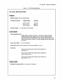
1-7. SPECIFICATIONS
. Module specifications are listed in Table 1-1.
These specifications are the performance
standards against which the module is tested.
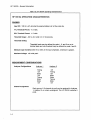
1-8. OPERATING CHARACTERISTICS
1-5. ACCESSORIES SUPPLIED
The following accessories are supplied with
the HP 16510A State/Timing module. Quantity
one unless shown otherwise.
•
Table 1-2 is a listing of the module operating
characteristics. The operating characteristics
are not specifications, but are typical operating
characteristics included as additional information for the user.
Operating manual set
1-9.
1-2
•
Service manual
•
16 Channel Lead Sets, grey tip
(HP 01650-61608) Qty 5
•
16 Channel Probe Cable
(HP 16510-61602) Qty 2
RECOMMENDED TEST
EQUIPMENT
Equipment required to test and maintain the
HP 1651 OA State/Timing Module is listed in
table 1-3. Other equipment may be substituted
if it meets or exceeds the critical specifications
listed in the table.
HP 1651 OA - General Information
Table 1-1. HP 16510A Specifications
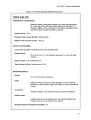
HP 16510A SPECIFICATIONS
PROBES
Minimum Swing: 600 mV
pea~-to-peak.
Threshold Accuracy:
Voltage Range
Accuracy
-2.0V to +2.0V
-9.9V to -2.1 V
+2.1V to +9.9V
±150 mV
±300 mV
±300 mV
Dynamic Range: ± 10 volts about the threshold.
STATE MODE
Clock Repetition Rate:
Single phase is 25 MHz maximum. With time or state counting,
minimum time between states is 60 ns. 80th mixed and demultiplexed clocking use master-slave clocl< timing; master clock must
follow slave clock by at least 10 ns and precede the next slave clock.
by >50 ns.
Clock Pulse Width:
~1 0
ns at threshold.
Setup Time: Data must be present prior to clock transition,
~
10 ns.
Hold Time:
Data must be present after rising clock transition on
all pods; 0 ns.
Data must be present after falling clock transition on
pods 1,3 and 5; 0 ns.
Data must be present after falling clock transition on
pods 2 and 4; 1 ns.
TIMING MODE
Minimum Detectable Glitch: 5 ns wide at the threshold.
1-3
HP 16510A - General Information
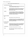
Table 1-2. HP 16510A Operating Characteristics
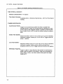
HP 16510A OPERATING CHARACTERISTICS
PROBES
Input RC: 100 Kn ±2% shunted by approximately 8 pF at the probe tip.
TTL Threshold Preset: +1.6 volts.
ECl Threshold Preset: -1.3 volts.
Threshold Range: -9.9 to +9.9 volts in 0.1 V increments.
Threshold Setting:
Threshold levels may be defined for pods 1, 2, and 3 on an individual basis and one threshold may be defined for pods 4 and 5.
Minimum Input Overdrive: 250 mV or 30% of the input amplitude, whichever is greater.
Maximum Voltage: ±40 volts peak.
MEASURMENT CONFIGURATIONS
Analyzer Configurations:
Analyzer 1
Timing
Off
state
Off
Timing
state
state
Off
Analyzer 2
Off
Timing
Off
State
State
Timing
State
Off
Channel Assignment:
Each group of 16 channels (a pod) can be assigned to Analyzer
1, Analyzer 2, or remain unassigned. The HP 16510A contains 5
pods.
1-4
HP 16510A - General Information
Table 1-2. HP 16510A Operating Characteristics (cont.)
STATE ANALYSIS
MEMORY
Data Acquisition:
1024 samples/channel.
TRACE SPECIFICATION
Clocks:
Five clocks are available and can be used by either one or two state
analyzers at any time. Clock edges can be ORed together and
operate in single phase, two phase demultiplexing, or two phase
mixed mode. Clock edge is selectable as positive, negative, or both
edges for each clock.
Clock Qualifier:
The high or low level of up to four clocks can be ANDed with the
clock specification. setup time: 20 ns; hold time: 5 ns.
Pattern Recognizers:
Each recognizer is the AND combination of bit (0, 1, or X) patterns
in each label. Eight pattern recognizers are available when one state
analyzer is on. Four are available to each analyzer when two state
analyzers are on.
Range Recognizers:
Recognizes data which is numerically between or on two specified
patterns (ANDed combination of Os and/or 1s). One range term is
available and is assigned to the first state analyzer turned on. The
maximum size is 32 bits.
Qualifier:
A user-specified term that can be anystate, nostate, a single pattern
recognizer, range recognizer, or logical combination of pattern and
range recognizers.
Sequence Levels:
There are eight levels available to determine the sequence of events
required for trigger. The trigger term can occur anywhere in the first
seven sequence levels.
Branching:
Each sequence level has a branching qualifier. When satisfied, the
analyzer will restart the sequence or branch to another sequence
level.
1-5
HP 16510A - General Information
Table 1-2. HP 16510A Operating Characteristics (cont.)
Occurrence Counter:
Sequence qualifier may be specified to occur up to 65535 times
before advancing to the next level.
Storage Qualification:
Each sequence level has a storage qualifier that specifies the states
that are to be stored.
Enable/Disable:
Defines a window of post-trigger storage. States stored in this window can be qualified.
Prestore:
Stores two qualified states that precede states that are stored.
TAGGING
State Tagging:
Counts the number of qualified states between each stored state.
Measurement can be shown relative to the previous state or relative
to trigger. Maximum count is 4.4 x 10¹² •
Time Tagging:
Measures the time between stored states, relative to either the
previous state or the trigger. Maximum lime between states is 48
hours.
With tagging on, the acquisition memory is halved; minimum time
between states is 60 ns.
SYMBOLS
Pattern Symbols:
User can define a mnemonic for the specific bit pattern of a label.
When data display is SYM BOL, mnemonic is displayed where the bit
pattern occurs. Bit pattern can include Os, 1s, and don't cares.
Range Symbols:
User can define a mnemonic covering a range of values. Bit pattern
for lower and upper limits must be defined as a pattern of Os and 1s.
When data display is SYMBOL, values within the specified range are
displayed as mnemonic + offset from base of range.
Number of Pattern and Range Symbols: 100 per analyzer.
Symbols can be down-loaded over RS-232-C.
1-6
HP 16510A - General Information
Table 1-2. HP 16510A Operating Characteristics (cont.)
TIMING ANALYSIS
TRANSITIONAL TIMING MODE
Sample is stored in acquisition memory only when the data changes. A time tag stored with each sample allows reconstruction of
waveform display. Time covered by a full memory acquisition varies
with the number of pattern changes in the data.
Sample Period: 10 ns.
Maximum Time Covered By Data: 5000 seconds.
Minimum Time Covered by Data: 10.24 Ils.
GLITCH CAPTURE MODE
Data sample and glitch information stored every sample period.
Sample Period:
20 ns to 50 ms in a 1-2-5 sequence dependent on s/div and delay
settings.
Memory Depth: 512 samples/channel.
Time Covered by Data: Sample period X 512.
WAVEFORM DISPLAY
Sec/div:
10 ns to 100 s; 0.01 % resolution.
Delay:
-2500 s to 2500 s; presence of data dependent on the number of
transitions in data between trigger and trigger plus delay (transitional
timing).
Accumulate:
Waveform display is not erased between successive acquisitions.
Overlay Mode:
Multiple channels can be displayecl on one waveform display line.
Primary use is to view summary of bus activity.
Maximum Number Of Displayed Waveforms: 24
1-7
HP 16510A - General Information
Table 1-2. HP 16510A Operating Characteristics (cont.)
TIME INTERVAL ACCURACY
Channel to Channel Skew: 4 ns typical.
Time Interval Accuracy:
± (sample period ... channel-to-channel sl<ew + 0.01 % of time interval
reading).
TRIGGER SPECIFICATION
Asynchronous Pattern:
Trigger on an asynchronous pattern less than or greater than
specified duration. Pattern is the logical AND of specified low, high,
or don't care for each assigned channel. If pattern is valid but duration is invalid, there is a 20 ns reset time before looking for patterns
again.
Greater Than Duration:
Minimum duration is 30 ns to 10 ms with 10 ns or 0.01 % resolution,
whichever is greater. Accuracy is +0 ns to -20 ns. Trigger occurs at
pattern + duration.
Less Than Duration:
Maximum duration is 40 ns to 10 ms with 10 ns or 0.01 % resolution,
whichever is greater. Pattern must be valid for at least 20 ns.
Accuracy is +20 ns to -0 ns. Trigger occurs at the end of the pattern.
Glitch/Edge Triggering:
Trigger on glitch or edge following valid duration of asynchronous
pattern while the pattern is still present. Edge can be specified as
rising, falling or either. Less than duration forces glitch and edge
triggering off.
1-8
HP 16510A - General Information
Table 1-2. HP 16510A Operating Characteristics (cont.)
MEASUREMENT AND DISPLAY FUNCTIONS
AUTOSCALE (TIMING ANALYZER ONLY)
Autoscale searches for and displays channels with activity on the pods assigned to the timing
analyzer.
ACQUISITION SPECIFICATIONS
Arming:
Each analyzer can be armed by the run key, the other analyzer, or
the Intermodule Bus.
Trace Mode:
Single mode acquires data once per trace specification; repetitive
mode repeats single mode acquisitions until stop is pressed or until
time interval between two specified patterns is less than or greater
than a specified value, or within or not within a specified range.
There is only one trace mode when two analyzers are on.
LABELS
Channels may be grouped together and given a six character name. Up to 20 labels in each
analyzer may be assigned with up to 32 channels per label. Primary use is for naming groups
of channels such as address, data, and control busses.
INDICATORS
Activity Indicators:
Provided in the Configuration, State Format, and Timing Format
menus for identifying high, low, or changing states on the inputs.
Markers:
Two markers (X and 0) are shown as dashed lines on the display.
Trigger:
Displayed as a vertical dashed line in the timing waveform display
and as line 0 in the state listing display.
MARKER FUNCTIONS
Time Interval:
The X and 0 markers measure the time interval between one point
on a timing waveform and trigger, two points on the same timing
waveform, two points on different waveforms, or two states (time
tagging on).
1-9
HP ·1651 OA - General Information
Table 1-2. HP 16510A Operating Character/sties (cont.)
. Delta States (State Analyzer Only):
The X and 0 markers measure the number of tagged states between
one state and trigger, or between two states.
Patterns:
The X and 0 markers can be used to locate the nth occurrence of a
specified pattern before or after trigger, or afler the beginning of
data. The 0 marl<er can also find the nth occurrence of a pattern
before or after the X marker.
Statistics:
X to 0 marl<er statistics are calculated for repetitive acquisitions.
Patterns must be specified for both markers and statistics are kept
only when both patterns can be found in an acquisition. Statistics
are minimum X to 0 time, maximum X to 0 time, average X to 0
time, and ratio of valid runs to total runs.
RUN/STOP FUNCTIONS
Run:
Starts acquisition of data in specified trace mode.
Stop:
In single trace mode or the first run of a repetitive acquisition, STOP
halts acquisition and displays the current acquisition data. For subsequent runs in repetitive mode, STOP halts acquisition of data and
does not change current display.
DATA DISPLAY/ENTRY
Display Modes:
State listing; timing waveforms; interleaved, time-correlated listing of
two state analyzers (time tagging on); time-correlated state listing
and timing waveform display (state listing in upper half, timing
waveform in lower half, and time tagging on).
Timing Waveform:
Pattern readout of timing waveforms at X or 0 marker.
Bases:
Binary, Octal, Decimal, Hexadecimal, ASCII (display only), and
User-defined symbols.
1-10
HP '16510A - General Information
Table "1-2. /-IP 16510A Operating Characteristics (cont.)
AUXILIARY POWER
Power Through Cables:
2/3 amp @ 5V per cable.
2 amp @ 5V per HP 16510A
Current Draw Per Card:
3 amp @ 5V per HP 16510A
OPERATING ENVIRONMENT
Temperature:
Instrument, 0 ° to 55 ° C (+32 ° to 13'1 ° F). Probe lead sets and
cables, 0 ° to 65 ° C (+32 ° to 149 ° F).
Humidity:
Instrument, up to 95% relative humidity at +40
°
C (+104
°
F).
Altitude: To 4600 m ("15,000 tt).
Vibration:
Operation: Random vibration 5-500 Hz, 10 minutes per axis, -0.3 9 (rms).
Non-operating:
Random vibration 5-500 Hz, 10 minutes per axis, - 2.41 9 (rms); and
swept sine resonant search, 5-500 Hz, 0.75 9 (O-peak), 5 minute
resonant dwell @ 4 resonances per axis.
1-11
HP 16510A - General Information
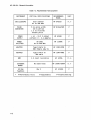
Table 1-3. Recommended Test Equipment
INSTRUMENT
OSCILLOSCOPE
PULSE
GENERATOR
POWER
SUPPLY
POWER
SPLITTER
ADAPTER
ADAPTER
DMM
EXTENDER
BOARD
CRITICAL SPECIFICATIONS
dual channel
dc to 300 MHz
5 ns pulse width
20 ns period
1.3 ns risetime
double pulse
+ or - 10.2 V output
current: 0 - 0.4 amperes
1-12
'USE*
HP 54201A
P, T
HP 8161A/020
P
HP 6216B
P
HP 11549A
P
HP 1250-0780
P
HP 1250-0082
P
3.5 digit resolution
HP 3478A
P, A
No Substitute
HP 16500-69004
A, T
HP 10100C
P
50 ohms
dc to 300 MHz
Type N male to
BNC female (qty 2)
Type N male to
BNC male
50 Ohm
Feedthru
*
RECOMMENDED
MODEL
P=Performance Tests
Qty 2
A=Adjustments
T=Troubleshooting
TABLE OF CONTENTS
INSTALLATION
2-1.
2-2.
2-3.
2-4.
2-5.
2-6.
2-7.
2-8.
2-9.
2-10.
2-11.
2-12.
Introduction. . . . . . . . . . . . . . . . . . . . . . . . . . . . . . . . . . . . . . . . . . . . . . . . . . . . . . . . . . . . . . . . . . . . . . . . . . ..
Initial Inspection .........................................................................
Preparation For Use ...................................................................
Power Requirements .... . . . . . . . . . . . . . . . . . . . . . . . . . . . . . . . . . . . . . . . . . . . . . . . . . . . . . . . . . . . . ..
Safety Requirements ...................................................................
Probe Cable Installation ...............................................................
Installation ..............................................................................
Module Installation .....................................................................
Operating Environment ................................................................
Storage ................................................................................
Packaging .............................................................................
Tagging For Service ...................................................................
2-1
2-1
2-1
2-1
2-1
2-1
2-1
2-2
2-4
2-4
2-4
2-4
HP 16510A - Installation
SECTION II
INSTALLATION
2-1. INTRODUCTION
2-4. POWER REQUIREMENTS
This section explains, how to initially inspect
the HP 1651 OA State/Timing Module, how to
prepare it for use, storage and shipment. Also
included are procedures for module
installation.
All power supplies required for operating the
HP 16510A State/Timing Module are supplied
to the module through the backplane
connector.
2-5. SAFETY REQUIREMENTS
2-2. INITIAL INSPECTION
Inspect the shipping container for damage. If
the shipping container or cushioning material
is damaged, it should be kept until the contents of the shipment have been checked for
completeness and the module has been
checked mechanically and electrically. The
contents of the shipment should be as listed in
the "ACCESSORIES SUPPLIES" paragraph located in Section I.
Procedures for checking electrical performance are in Section III. If the contents of the
container are incomplete, there is mechanical
damage or defect, or the instrument does not
pass the performance tests, notify the nearest
Hewlett-Packard office.
If the shipping container is damaged, or the
cushioning material shows signs of stress,
notify the carrier as well as the
Hewlett-Packard office. Keep the shipping
material so the carrier can inspection it. The
Hewlett-Packard office will arrange for repair
or replacement at Hewlett-Packard's option
without waiting for claim settlement.
Specific warnings, cautions, and instructions
are placed wherever applicable throughout the
manual. These must be observed during all
phases of operation, service, and repair of the
module. Failure to comply with them violates
safety standards of design, manufacture, and
intended use of this module. Hewlett-Packard
assumes no liability for the failure of the customer to comply with these safety
requirements.
2-6. PROBE CABLE INSTALLATION
The HP 16510A State/Timing Module comes
with probe cables installed by the factory. If a
cable is to be switched or replaced, refer to
"PROBE CABLE REPLACEMENT" in Section
VI of this manual.
2-7. INSTALLATION
Do not install, remove or replace the
module in the instrument unless the instrument power is turned off.
2-3. PREPARATION FOR USE
I
WARNING
I
Read the Safety Considerations in the
front of this manual and in Section I
before installing or operating this
module.
The HP 16510A State/Timing Module will take
up one slot in the card cage. For every additional HP 16510A State/Timing Module you install, you will need an additional slot. They
may be installed in any slot and in any order.
The installation procedure for the module is
shown step-by-step in paragraph 2-8.
2-1
HP 16510A - Installation
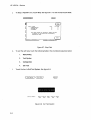
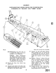
2-8. MODULE INSTALLATION
The effects of ELECTROSTATIC DISCHARGE can damage electronic
components. Use grounded wriststraps and mats when you are performing any kind of service to this module.
INSTALLATION CONSIDERATIONS:
•
The HP 16510A State/Timing Module(s) can be installed in any available card slot and in
any order.
•
Cards or filler panels below the empty slots intended for module installation do not have
to be removed.
•
The probe cables do not have to be removed to install the module.
PROCEDURE:
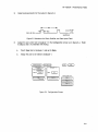
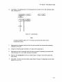
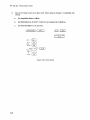
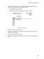
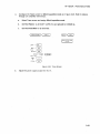
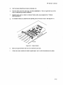
a.
Turn instrument power switch off, unplug power cord and disconnect any input
connections.
b.
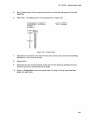
Starting from the top, loosen thumb screws on filler panel(s) and card(s).
c.
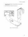
Starting from the top, begin pulling card(s) and filler panel(s) out half way. See figure 2-1.
TOP CARD
¢:Jl
NEXT LOWEST
<
12
1IIIIOI!Xl I
Figure 2-1. End plate Overlap
2-2
HP 1651 OA - Installation
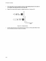
d.
Lay the cable(s) flat and pointing out to the rear of the card. See figure 2-2.
e.
Slide the analyzer card approximately half way into the card cage.
f.
If you have more analyzer cards to install repeat step d and e.
Figure 2-2. Cable Position
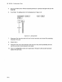
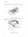
g.
Firmly seat bottom card into backplane connector. Keep applying pressure to the center
of card endplate while tightening thumb screws finger tight.
h.
Repeat for all cards and filler panels in a bottom to top order. See figure 2-3.
NEXT
HIGHEST
BOTTOM
CARD
leaclltX1S
Figure 2-3. Endplate Overlap
i.
Any filler panels that are not used should be kept for future use. Filler panels must be installed in all unused card slots for correct air circulation.
2-3
HP 16510A - Installation
2-9. OPERATING ENVIRONMENT
2-11. PACKAGING
The operating environment is listed in table 1-2
of Section I of this manual. Note should be
made of the non-condensing humidity limitation. Condensation within the instrument can
cause poor operation or malfunction.
Protection should be provided against internal
condensation.
The following general instructions should be
used for repacking the module with commercially available materials.
The HP 16510A State/Timing Card will operate
at all specifications within the temperature and
humidity range given in table 1-2. However,
reliability is enhanced when operating the
module within the following ranges.
•
Wrap module in anti-static plastic.
•
Use a strong shipping container. A
double-wall carton made of 350 lb. test
material is adequate.
•
Use a layer of shock-absorbing material
70 to 100 mm (3 to 4 inch) thick around
all sides of the module to provide firm
cushioning and prevent movement inside the container.
•
Seal shipping container securely.
•
Mark shipping container FRAGILE to
ensure careful handling.
•
In any correspondence, refer to module
by model number and board number.
Temperature: +20 to +35° C (+68 to +95° F)
Humidity: 20% to 80% non-condensing
2-10. STORAGE
The module may be stored or shipped in enviro~ments within the following limits:
Temperature: _40° C to +75 0 C
Humidity: Up to 90% at 65 0 C
Altitude: Up to 15,300 meters (50,000 feet)
2-12. TAGGING FOR SERVICE
The module should also be protected from
temperature extremes which cause condensation on the module.
2-4
If the module is to be shipped to a
Hewlett-Packard office for service or repair, attach a tag showing owner (with address),
complete board number, and a description of
the service required.
TABLE OF CONTENTS
PERFORMANCE TESTS
3-1.
3-2.
3-3.
3-4.
3-5.
3-6.
3-7.
3-8.
3-9.
3-10.
3-11.
3-12.
3-13.
3-14.
3-15.
3-16.
3-17.
Introduction. . . . . . . . . . . . . . . . . . . . . . . . . . . . . . . . . . . . . . . . . . . . . . . . . . . . . . . . . . . . . . . . . . . . . . . . . . .. 3-1
Recommended Test Equipment ....................................................... 3-1
Test Record ............................................................................ 3-1
Performance Test Interval ............................................................. 3-1
Performance Test. Proceclures ......................................................... 3-1
Test Connector ......................................................................... 3-1
Clock, Qualifier, ancl Data Input Tests ................................................. 3-2
Clock, Qualifier, and Data Input Tests 1 .............................................. 3-2
Clock, Qualifier, and Data Input Tests 2 .............................................. 3-6
Clock, Qualifier, and Data Input Tests 3 .............................................. 3-9
Clock, Qualifier, and Data Input Tests 4 ............................................. 3-12
Clock, Qualifier, and Data Input Tests 5 ............................................. 3-16
Clock, Qualifier, and Data Input Tests 6 ............................................. 3-19
Clock, Qualifier, and Data Input Tests 7 ............................. : ............... 3-22
Glitch Test ............................................................................ 3-25
Threshold Accuracy Test ............................................................. 3-30
Dynamic Range Test ................................................................. 3-37
HP 16510A - Performance Tests
SECTION III
PERFORMANCE TESTS
3-1. INTRODUCTION
The procedures in this section test the HP
16510A State/Timing Analyser's electrical performance using the specifications listed in
Section I as the performance standards. All
tests can be performed without access to the
interior of the instrument. At the end of this
section is a form that can be used as a record
of performance test results.
3-2.
RECOMMENDED TEST
EQUIPMENT
Equipment recommended for performance
tests is listed in table 1-3. Any equipment that
satisfies the critical specifications given in the
table may be substituted for the recommended
models.
3-3. TEST RECORD
Results of performance tests may be tabulated
on the Performance Test Record (table 3- 1 ) at
the end of the procedures. The test record lists
all of the tested specifications and their acceptable limits. The results recorded on the
test record may be used for comparison in
periodic maintenance and troubleshooting or
after repairs and adjustments have been made.
3-5.
PERFORMANCE TEST
PROCEDURES
All performance tests should be performed at
the instruments environmental operating. temperature and after a 15-minute warm up period.
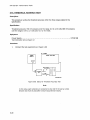
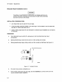
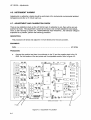
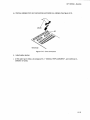
3-6. TEST CONNECTOR
The performance tests and adjustments
require connecting pulse generator outputs to
probe pod inputs. Figure 3-1 is a test connector that may be built to allow testing of multiple channels (up to eight at one time). The
test connector consists of a BNC connector
and a length of wire. Connecting more than
eight channels to the test connector at a time
will induce loading of the circuit and true signal representation will degrade. Test results
may not be accurate if more than eight channels are connected to the test connector.
The Hewlett-Packard part number for the BNC
connector in figure 3-1 is 1250-1032. An
equivalent part may be used in place of the
Hewlett-Packard part.
3-4. PERFORMANCE TEST INTERVAL
Periodic performanc(~ verificalion of tile HP
16510A State/Timing Module is required at two
year intervals. The instrument's performance
should be verified after it has been serviced, or
if improper operation is sLlspected. Further
checks requiring access to the interior of the
instrument are included in the adjustment section, but are not required for the performance
verification.
18519/EX9711e-a7
Figure 3-1. Test Connector
3-1
HP 16510A - Performance Tests
3-7. CLOCK, QUALIFIER, AND DATA INPUTS TESTS
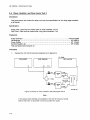
3-8. Clock, Qualifier, and Data Inputs Test 1
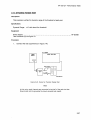
Description:
This test verifies maximum clock rate with counting mode and the setup and hold times for the
falling edge of all clocks to pods 1,3 and 5.
Specification:
Clock repetition rate: With time or state counting mode on, minimum time between states is 60
ns.
Hold time: Data must be present after falling edge of all clocks; 0 ns.
Setup time: Data must be present prior to clock transition; ~1 Ons.
Equipment:
Pulse Generator ...................................................................... HP 8161 A/020
Oscilloscope ............................................................................. HP 54201 A
Power Splitter :........................................................................... HP 11549A
50 Ohm Feedthru (2) .................................................................... HP 101 OOC
Test Connectors (2) see figure 3-1
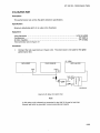
Procedure:
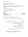
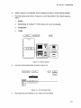
1.
Connect the HP 16510A and test equipment as in figure 3-2.
OSCILLOSCOPE
PULSE GENERATOR
A
HP 16S99A
LOGIC ANALYZER
0 B
p
R
o
B
P
0
0
E
S
188111TUII11J17
Figure 3-2. Setup for Cloc/(, Qualifier, and Data Inputs Test 1
Note
In this setup, eigtlt channels are connected to test eight channels at
Ground lead must be grounded to ensure accurate test results.
3-2
a time.
HP 16510A - Performance Tests
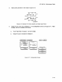
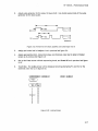
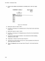
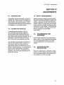
2.
Adjust pulse generator for the output in figure 3-3.
100
.
I I 1.
- - - -
69n.
n
~19n.
DATA AND elK - - - - . . .
----
---II"'~I
-
~1.9V
- - - - 1.8V
'------
S1.3V
Figure 3-3. Waveform for C/oc/(, Qualifier, and Data Inputs Test 1
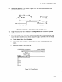
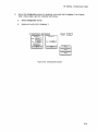
3.
Assign the pod under test to Analyzer 1 in the Configuration screen as in figure 3-4. Refer
to steps a and b if unfamiliar with menus.
a.
Touch Type field I)f Analyzer 1 and set to State.
b.
Assign the pod to be tested to Analyzer 1.
~ (
( S ta te/Tim1 ng C) (conn gura t1 on)
Analyzer
Name I
Type l
(
(
Analyzer 2
I
MACHINE 1
State
)
)
Pod 1
l ........ uuuu
I
Run
Type l
I
(
Off
)
POd 5
----------------
Unassigned Pods
Pod 2
---------------Pod 3
---------------Pod 4
----------------
Figure 3-4. Configuration Screen
3-3
HP 1651 OA - Performance Tests
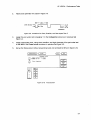
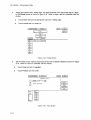
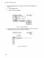
4.
Assign appropriate clock, falling edge, and 8 channels of the pod under test to a label in
the Format screen as shown in figure 3-5. Refer to steps a and b if unfamiliar with the
menus.
a.
Touch Clock field and set appropriate clock for a falling edge.
b.
Touch Labels and turn labels on.
S til te/Timi ng
c) (
F'ormll t 1
~ (
)
)
Clock
Run
( Symbo IS)
Pod Cl
TTL
Clock
...
....
BIT
Off
Ofr
Off
Ofr
Off
Off
Ofr
~
. ...
I······· .•••••••• I
Figure 3-5. Format Screen
5.
Set the Trace screen without sequencing levels and set Count to States as shown in figure
3-6. Refer to a and b if unfamiliar with the menus.
a.
Touch Count and set to Anystate.
b.
Touch Prestore and set to Off.
Stete/Ttming C)
cp
0
Trece 1
Sequence Levels
Hhile storing -no stele H
TRIGGER on He"
1 times
Store -enyslllte-
~ (
Run
)
( Brenches
Off
Count
)
( Stetes
( Prestore
Off
Lebel>
Bllse>
e
b
c
d
@C)
~
~
~
~
~
Fiuure 3-6. Trace Screen
3-4
)
HP 16510A - Performance Tests
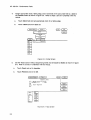
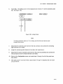
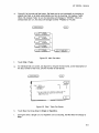
6.
Touch Run. The Listing screen will be displayed and will show F's for the channe"ls under"
test. See figure 3-7.
(
Stote/Tlming
( MOrak,er S
c)
(LiSting
1
2
3
4
5
5
~,",*7----,
B
9
10
5 to tes
Reletive
FF
FF
FF
FF
FF
FF
FF
FF
FF
FF
FF
FF
11
FF
12
13
14
FF
15
Run
)
I BIT II
'---_--' I Hel< II
o
1 )
FF
FF
Figure 3-7. Usting Screen
Note
To ensure consistent pattern of Ps in listing, use Roll field and knob to scroll
through State Usting.
7.
Disconnect the channels under test from the test connector and connect the remaining
channels on this pod.
8.
ASSign the remaining eight channels to the label, then repeat step 6.
9.
Disconnect the pod of channels under test from the probe tip assembly and connect the
next pod (pods 1,3 or 5) of data channels to be tested.
10.
Return to the Configuration screen and repeat steps 3 through 9 until all the pods have
been tested.
11 . After pods 1,3 and 5 have been tested, repeat steps 3 through 10 assigning the next clock
(clocks J ,K,L.M or N).
3-5
HP 16510A - Performance Tests
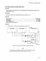
3-9. Clock, Qualifier, and Oa ta Inputs Test 2
Description:
This performance test verifies the setup and hold time specification for the rising edge transition
of all clocks.
Specification:
Setup Time: Data must be present prior to clock transition; ~1 0 ns.
Hold Time: Data must be present after rising clock transition; 0 ns.
Equipment:
Pulse Generator ...................................................................... HP 8161 Aj020
................................•..........................................•. H P 54201 A
Power Splitter.......... . .... ................... .............. ............ ................ HP 11549A
50 Ohm Feedthru (2) .................................................................... HP 10100C
Test Connectors (2) see figure 3-1
Osc~lIoscope
Procedure:
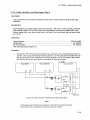
1.
Connect the HP 16510A and test equipment as in figure 3-8.
HP 16500A
OSCILLOSCOPE
PULSE GENERATOR
A
LOGIC ANALYZER
0 B
P
R
o
B
P
0
0
E
S
1151 e/TUall 1117
Figure 3-8. Setup for Clock, Qualifier, and Data Inputs Test 2
Note
In ttliS S(~tup, eigllt channels are connected to test half of the pod at
Ground lead must flO grounded to ensure accurate test results.
3-6
a time.
HP 16510A - Performance Tests
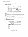
2.
Adjust pulse generator for Olltput in figure 3-9.
DATA AND eLK ~
10ns
u,...-----.. l:::----
~1. 9V
- - - - 1.6V
- S1.3V
1111.",..,...,
Figure 3-9. Waveform for Clock, Qualifier, and Data Inputs Test 2
3.
Assign the pod under test to Analyzer 1 in the Configuration screen as in previous test
figure 3-4.
4.
Assign appropriate clock, rising clock transition, and eight channels of the pod under test
to the label in the Format screen as shown in previous test figure 3-5.
5.
Set up the Trace screen without sequencing levels and set Count to Off as in figure 3-10.
S til te/T1ml ng C )
~
Trece 1
Sequence Levels
Hhlle storing -no steteTRIGGER on -eI t lmes
~ {
Run
( Brenches
Off
Store Henystete"
(
Count
Of f
( Prestore
Off
Lebel>
Bese>
...--
e
b
c
d
)
)
)
~
~
QQ
QQ
QQ
QQ
Figure 3-10. Trace Screen
3-7
HP16510A - Performance Tests
6.
Touch Run. The Listing screen will be displayed and will list 0 for the channels under test as
in figure 3-11 .
Stete/Timing
Merkers
Off
c)
(LiSting
1 )
Run
)
.
I BIT I
"--- Q§CJ
1
00
2
3
.:I
5
6
7
e
9
10
11
12
13
14
15
16
00
00
00
00
00
00
00
00
00
00
00
00
00
00
00
Figure .3-11. Usting Screen
7.
Disconnect the channels under test from the test connector and connect the remaining eight
channels of the pod.
8.
Assign the remaining eight channels to the label, then repeat step 6.
9.
Disconnect the pod of channels under test from the probe tip assembly and connect the next
pod of data channels to be tested.
10.
Return to Configuration screen and repeat steps 3 through 9 until all pods have been tested.
11. After all pods have been tested, repeat steps 3 through 10 for each clock.
3-8
HP 16510A - Performance Tests
3-10. Clock, Qualifier, and Data Inputs Test 3
Description:
This performance test verifies the hold time specifications for the falling clock transitions of all
clocks to pods 2 and 4.
Specification:
Hold Time: Data must be present after falling clock transitions; 1 ns.
Equipment:
Pulse Generator ...................................................................... HP 8161 Aj020
Oscilloscope ............................................................................. H P 54201 A
Power Splitter.. .. ......... ... ........ ............. .. . ... ..... ........... . ... . ....... ..... HP 11549A
50 Ohm Feedthru (2) .................................................................... H P 101 ooe
Test Connectors (2) see figure 3-1
Procedure:
1.
Connect the HP 16510A and test eQuipment as in fiqure 3-12.
HP 16599A
OSCILLOSCOPE
A
PULSE GENERATOR
LOGIC ANALYZER
A
ClK
590
P
P
R
0
B
E
S
0
p
p
0
DATA BITS
a
DATA
590
R
B
E
S
0
FIGURE
3-1
0
0
a
1151UTUIl/l..."
Figure 3·12. Setup for Clock, Qualifier, and Data Inputs Test 3
Note
In this setup, eight channels are connected to test half of the pod at
Ground lead must be grounded to ensure accurate test results.
a time.
3-9
HP 16510A - Performance Tests
2.
Adjust the pulse generator for outputs in figure 3-13. Use double pulse mode of the pulse
generator for the clock waveform.
n=----
j4--4en.~
n
- r1~1en.
-
~
elK - - - - . . .
L -_ _ _....
-
.
-
----
~1.9V
1.6V
- S1.3V
1......----8en·-----tl~~1
---IE
~11n.
DATA----...
~1.9V
- - - - 1.6V
- S1.3V
-
Figure 3-13. Waveforms for Clock, Qualifier, and Data Inputs Test 3
3.
Assign the pods under test to Analyzer 1 in the Configuration screen as in previous test
figure 3-4.
4.
Assign the falling edge of the appropriate clock and eight channels to label as in previous
test figure 3-5.
5.
Set up the Trace screen without sequencing levels and Count Off as in previous test figure
3-10.
6.
Touch Run. The Listing screen will be displayed and alternate F's and O's will be displayed
as in figure 3-14.
State/Timing
Markers
Off
c)
(LiSting
1 )
~ (
)
.
~
'----'
~
9
FF
00
FF
00
FF
00
FF
00
FF
10
00
11
FF
00
FF
1
2
3
4
5
5
7
B
12
13
14
15
16
00
FF
00
Figure 3-14. Usting Screen
3-10
Run
HP 1651 OA - Performance Tests
7.. Disconnect the channels undor test from the test connector and connect the remaining
channels of the pod.
8.
Assign the remaining night channels to the label, then repeat slep 6.
9.
Disconnect the pod of data channels under test from the probe tip assembly and connect
the next pod (pods 2 and 4) of data channels to be tested.
10.
Return to Configuration screen and repeat steps 3 through 9 until both pods have been
tested.
11. After pods 2 and 4 are tested, repeat steps 4 through 10 with other clocl<s ·(J,K,L,M and N).
3-11
HP ·16510A - Performance Tests
3-11. Clock, Qualifier, and Data Inputs Test 4
Description:
This test verifies maximum clock rate with counting mode and the setup times for the falling
edge of all clocl<s to pods 2 and 4.
Specification:
Clock repetition rate: With time or state counting mode on, minimum time between states is 60
ns.
Setup time: Data must be pre:3ent prior to clocl< transition, ~1 Ons.
Equipment:
Pulse Generator .............
Oscilloscope .................
Power Splitter ......
50 Ohm Feedthru (2)
Test Connectors (2) see figure 3-1
0
•••••••••••
o ••••••••••
0
••••
0
••
0
••••••••••••••••••••••••
00.0
•••
0
•••
00.00
•••
00
••
0
0
•••••••••••••••••••
•••••
0
o.
0
•••••••••••
00
HP 8161A/020
HP 54201 A
HP 11549A
HP 10100C
•••
o • • o. • • • • • • • • • • • • • • • • • • • • • • • • • • • • • • • • • • • • • • • • • • • • • • • • • • • • • • • • • • • •
000
••
00
•••••••
000.00.0
•••
000
••••
00
••••••••••
0.0.0
0.00
••••
0
•••••••
Procedure:
1.
Connect the H P 16510A and test equipment as in figure 3-15.
HP 16599A
OSCIllOSCOPE
A
lOGIC ANALYZER
PULSE GENERATOR
A
B
ClK
S9n
P
R
0
B
E
S
FIGURE
3-1
P
D
0
elK BIT
DATA BITS
P
R
B
8
DATA
S9n
0
FIGURE
3-1
P
0
D
E
5
Figure 3-15. Setup for Clock, Qualifier, and Data Inputs Test 4
Note
In this setup, eigf1t channels are connected to test eight cllannels at
Ground lead must be grounded to ensure accurate test results.
3-12
a time.
1851I/TU1Vl...e7
HP 16510A - Performance Tests
2.
Adjust pulse generator for the output in figure 3-16.
~6eNS~
~,eNS
I
~
ClK--=:J
~"NS
I
~
DATA--=:J
~6eNS~
1U1IM"'1-...J
Figure 3-16. Waveform for Clock, Qualifier, and Data Inputs Test 4
3.
Assign the pod under test to Analyzer 1 in tile Configuration screen as in figure 3-17. Refer
to steps a and b if unfamiliar with menus.
a.
Touch Type field of Analyzer 1 and set to State.
b.
Assign the pod to be tested to Analyzer 1.
5 ta te/Tim1 ng
c)
Type l
(
MACHINE I
(
State
Run
Analyzer 2
Analyzer 1
Name I
§) (
(Conf 1gura t 1on)
)
)
Type
l
(
Off
)
Unass 1gned Pods
Pod 2
........ ::::::::
(
Pod 5
l
----------------
Pod I
---------------POd 3
---------------Pod <I
----------------
Figure
~1-17.
Configuration Screen
3-13
HP 1651 OA - Performance Tests
4.
Assign appropriate clock, falling edge, and eight channels of the pod under test to a label
in the Format screen as shown in figure 3-18. Refer to steps a and b if unfamiliar with the
menus.
a.
Touch Clock field and set appropriate clocl< for a falling edge.
b.
Touch Labels and turn labels on.
State/TImlng
c) (
Format 1
Clock
~ (
)
)
Run
( Symbol s )
Pod C2
TTL
Clock
I ~I
~
BIT
Off
Of f
Off
Of f
Off
Off
Off
--------::::::::
15 ... 87 .... 0
81········"'''''''''''''''''''·1
Pol
Figure 3-18. Format Screen
Set the Trac~ screen without sequencing levels and set COLint to States as shown in figure
3-19. Refer to a and b if unfamiliar with tile menus.
5.
a.
Touch Count and SE!t to Anystate.
b.
Touch Prestore and set to Off.
State/TImlng
cp
0
Lebel>
Bese>
--a
b
c
d
c)
Trace 1
Sequence Levels
Hhlle storlng "no state"
TRIGGER on "a"
1 t lmes
Store "anystate"
~
~
~
~
~
~
Figure 3-19. Trace Screen
3-14
~ (
Run
)
( Branches
Off
Count
)
( States
)
( Prestore
Off
HP "16510A - Performance Tests
6.
Touch Run. The Listing screen will be displayed and will sllow P's for the channels under
test. See figure 3-20.
(
Stote/Timing
(
Morkers
Off
c) (
6
:z
6
9
10
II
12
13
14
15
I
)
~
(
Run
)
I BIT II
Q§CJI
0
I
2
3
4
5
Listing
Stotes
Relotive
FF
FF
FF
FF
FF
FF
FF
FF
FF
FF
FF
FF
FF
FF
FF
FF
Figure 3-20. Listing Screen
Note
To ensure consistl~nt pattorn of F's in listing, use Roll field and knob to scroll
through Stale Listing.
7.
Disconnect the channels under test from the test connector and connect the remaining
eight channels to be tested.
8.
Assign the remaining eight channels to the label, and repeat step 6.
9.
Disconnect the pod of channels under test from the probe tip assembly and connect the
next pod (pods 2 ancl 4) of data channels to be tested.
10.
Return to the Configuration screen and repeat steps 3 through 9 until all the pods have
been tested.
11. After pods 2 and 4 have been tested, repeat steps 3 through 10 assigning the next clock
(J,K,L,M and N).
3-15
HP "1651 OA - Perfolll1ance Tests
3-12. Clock, Qualifier, and Data ~'!ts Test 5
Description:
This performance test verifies the minimum swing voltages of the input probes and the maximum clock rate of the HP '165'1 OA when it is in single phase mode.
Specification:
Minimum swing: 600 mV peak-la-peak
Clock repetition rate: Single phase is
Clock pulse width:
~1
2~5
MHz maximum.
a ns at threshold.
Equipment:
Pulse Generator ...................................................................... HP 8161A/020
Oscilloscope .................... ~ . . . . . . . . . . . . . . . . . . . . . . . . . . . . . . . . . . . . . . . . . . . . . . . . . . . . . . .. HP 54201 A
50 Ohm Feedthru (2) .................................................................... HP 10100C
Test Connectors (2) see figure 3-1
Procedure:
1.
Connect the HP 16510A and test equipment as in figure 3-21.
OSCIllOSCOPE
OA
HP 16500A
lOGIC ANALYZER
PULSE GENERATOR
F-
qA
-
qB
1-
ClK
--
500
,.--, GND
-illI
FIGURE
3-1
---.J
P
R
B
E
S
0
I
P
0
D
-
ClK BIT
DATA BITS
DATA
--
500
-illI
FIGURE
3-1
La
a"
f----,
GND
i--I
p
p
R
B
E
S
0
0
D
i---
18S111Tsta/1 ...7
Figure 3-21. Setup for Clock, Qualifier, and Data Inputs Test 5
Note
In this setup, eigflt channels are connected to test /1alf of t/1e pod at a time.
Ground lead must be grounded to ensure accurate test results.
3-16
HP 16510A - Performance Tests
2.
Adjust pulse generator for the output in figure 3-22. Use double pulse mode of the pulse
generator for the clock pulse.
,......
1 1 - - - - 8ens - - - -...
.,~I
--a.I
I:::
1.9V
- - - - 1.6V
- 1.3V
('-2enS
DATA....::.J
-
!4-- 4ens-.f
~11~
r= 1ens
~
elK ----....
-
n ---...I1E-----
1 9V
- - - - 1.• 6V
•
L...
1.3V
110111"M'H/...a7
Figure 3-22. Waveforms (or Clock, Qualifier, and Data Input Test 5
3.
Assign pod under test to Analyzer 1 as in previous test rigure 3-4.
4.
Assign appropriate clocl(, rising clock edBe, and channels under test to label in Format
screen as in previous test figure 3-5.
5.
Set up the Trace screen without sequencing levels, and Count Off as in previous test figure
3-10.
6.
Touch Run. The Listing screen will be displayed showing alternating F's and O's for the
channels under test as in figure 3-23.
Stote/Timlng
Markers
Off
c)
(LiSting
1 )
~ (
Run
]
.
I BIT
I Hex
1
2
3
4
5
6
7
8
9
10
11
12
13
14
15
16
FF
00
FF
00
FF
00
FF
00
FF
00
FF
00
FF
00
FF
00
Figure 3-23. Listing Screen
3-17
HP 16510A - Performance
Te~jts
7.
Disconnect the channels under test from the test connector and connect the remaining
channels.
8.
Repeat step €L
9.
Disconnect the pod of data channels under test from the probe tip assembly and connect
the next pod of data channels to be tested.
10. Return to Configuration
with each clock.
3-18
~creml
ancl repeat steps 3 through 9 until all pods have been tested
HP 16510A - Performance Tests
3-13. Clock, Qualifier, and Data Inputs Test 6
Description:
This performance test verifies the maximum clock rate for mixed mode clocking during state
operation.
Specification:
Clock repetition rate: Single phase is 25 MHz maximum. With time or state counting, minimum
time between states is 60 ns. Both mixed and demultiplexed clocl<ing use master-slave clock
timing; master cloGk must follow slave clock by at least 10 ns and precede the next slave clock
by > 50 ns.
Equipment:
Pulse Generator ...................................................................... HP 8161 A/020
Oscilloscope ............................................................................. HP 54201 A
50 Ohm Feedthru ............. . ... .... .. .. . ....... .... ... ... . . . . .. ... ..... .. ......... .... HP 101 OOC
Test Connectors (2) see figure 3-1
Procedure:
1.
Connect the HP 1G51 OA and test equipment as in figure 3-24 by connecting channels 0-3
and 8-11 of tile pod under test to the test connector. On the slave clock transition the four
bits of the lower byLe arc transferred to the logic analyzer, and on the master clock transition. the four bits of th(~ upper byte are transferred to tile logic analyzer.
HP 16500A
lOGIC ANALYZER
PULSE GENERATOR
OSCIllOSCOPE
r---
OA
-r~
OA
OB
l-
i -
ClK
--
500
rrn
WI
---., GND
FIGURE
3-1
---J
I ClK BIT
P
R
0
B
E
S
P
D
0
~
DATA BITS
DATA
-
500
rm
llil FIGURE
3-1
...La
--
---., GND
P
R
B
E
S
0
P
O·
D I---
a'
1851.ITSI5II...e7
Figure 3-24. Setup for Glock, Qualifier, and DatCllnputs Test 6
Note
In this setup, eigflt ctlannels are connected to test half of the pod at one time.
Grounc/ lead l'1lJst bf~ grounded to ensure accurate test results.
3-19
HP 16510A - PerformC\nce Tests
2.
Adjust pulse generator for the output in figure 3-25. Use double pulse mode of the pulse
generator for clocl< waveform.
I....41----
~
IMI----------
n
10n8
elK
, ----
60na ---I~~I
-----.....
I
'-------.....
~-.l1
120n8 - - - - - -....
!
1...20n8~1
DATA - - ; 1 - - - - - - 1
I
~1.9V
- - - - 1.6V
- - - - S1.3V
==== ~~6ev
...- - - - - - S1.3V
I
~40n8~
,.a'~121~7
Figure .'3-25. Waveforms for Clock, Qualifier, and Data Inputs Test 6
3.
Assign the pods under tost to Analyzer 1 in Configuration screen as in previous test
figure 3-4.
4.
Set up the Format screen as in figure 3-26, assigning the falling clock transition as master and the rising transition as slave. Refer to steps a through c if unfamiliar with the
menus.
a.
Touch Clock field, then touch Mixed Clocks.
b.
Assign falling clocl< transition to master clock and rising clocl< transition to slave
clock.
c.
Assign all channels to pod under test.
(
State/Timing
(
c) (
Format 1
~
)
Master Clock
J(
_ _ _ _ _ Jt
Slave Clock
~J~
Pod Cl
TTL
Moster I Slave
1~lpol ----****----****
15
87 .0 •• 0
"
,
BIT
Off
81················ 1
Off
Off
Off
Off
Off
Off
Figure 3-26. Format Screen
3-20
(
Run
)EJ
HP16510A - Performance Tests
5.
Set up Trace screen without sequencing levels, as in previous test figure 3-6, but with
Count Off.
0
6.
Press RUN. The Listing screen will be displayed as in figure 3-27.
(
Stete/Tim1ng
(
Merokfe[S
c)
(LiSting
I )
~ (
Run
)
I BIT
'---_--' I Hex
o
0000
2
0000
I
OFOF
3
OFOF
4
0000
5
OFOF
6
0000
8
0000
10
II
12
0000
14
0000
7
OFOF
9
OFOF
OFOF
0000
13
OFOF
IS
OFOF
Figure 3-27. Listing Screen
7.
Disconnect the channl~ls under test from the lest connector and connect the remaining
channels (4-7 and 12- 15) of the pod.
0
8.
Repeat step 6.
9.
Disconnect the pod of data channels under test from the probe tip assembly and connect the next pod of (lata channels to be tested.
10. Return to Configuration screen and repeat steps 3 through 9 until all pods have been
tested with each clock.
3-21
HP '16510A - Performance Tests
3-14. Clock, Qualifier, and Data Inputs Test 7
Description:
This performance test verifies the maximum clock rate for demultiplexed clocking during state
operation.
Specification:
Clock repetition rate: Single phase is 25 MHz maximum. With time or state counting, minimum time between states is 60 ns. Both mixe'd and demultiplexed clocking use master-slave
clock timing; master clock must follow slave clocl< by at least 10 ns and precede the next
slave clock by > 50 ns.
Equipment:
Pulse Generator ................................................................... HP 8161A/020
Oscilloscope ........................................................................... H P 54201 A
50 Ohm Feedthru ..................................................................... HP 101 OOC
Test Connectors (~~) see figure 3-1
Procedure:
1.
Connect the HP 1651 OA and test equipment as in figure 3-28 by connecting channels 0 7 of the pod under test to test connector.
OSCIllOSCOPE
o~r~
HP 16500A
lOGIC ANALYZER
PULSE GENERATOR
qA
-
OB
1-
ClK
-
500
I
r-, GND
FIGURE
3-1
t--'
IT
ClK BIT
P
R
B
E
S
0
P
0
D
:---
DATA BITS
DATA
--
500
rm
Ull
FIGURE
3-1
LLe
e'
r-,GND
p
p
R
0
B
E
S
0
D
-
~
le~I'/T885/1..a7
Figure 3-28. Setup for Clock, Oualifier, and Data Inputs Test 7
Note
In this s,?tup, eigf1t channels are connected to test 1181f of the pod at one time.
Ground lead must be grounded to ensure accurate test results.
3-22
H P 1651 OA - Performance Tests
2.
Adjust pulse generator for the output in figure 3-29. Use doulJle pulse mode of pulse
generator for clocl{ waveform.
I....4..._-elK
60ns ---I~~I
n
~
10ns
------....
I
1l0iii4
__- - - - - - 120ns
r-----~1.9V
I
'-------....
---- 1.6V
- - - - Sl.3V
-------I~~I
14
I
20
- - - - ;;::1.9V
1.6V
' - - - - - - Sl.3V
I
DATA - - ; j r - - - - - - - 4
I
I
"'-40ns~
nS~1
----
11111.,...121...7
Figure 3-29. Waveform[J for Clock, 'Qualifier, and Data Inputs Test 7
3.
Assign the pods under test to Analyzer 1 in Configuration screen as shown in previous
test figure 3-4.
4.
Set up the Format scwen as in figure 3-30, assigning the falling clock transition as master and the rising transition slave. Refer to steps a through c if unfamiliar with the menus.
a.
Touch Master I Slave, then Demultiplex.
b.
Assign falling clocl< transition to master clock and rising clock transition to slave
clock.
'
c.
Assign all channels to pod under test.
Sttlte/Tlming C) (
Formtlt 1
~ (
Mtlster Clock
) {
Sltlve Clock
]
(_JJ._ _~_ _-" ......
J_t_ _ _ _- - "
Run
~
~
Pod CI
TTL
MtI~ter
1~lpOI
BIT
orr
~
I Sltlve
________ UUUU
15
,
.,
87
,
...
0
I················ 1
Off
Of f
Off
orr
Off
Off
Figure 3-30. Format Screen
3-23
HPI6510A - Performance Tests
5.
Set up the Trace screen without sequencing levels as in previous test figure 3-6 but with
Count Off.
6.
Touch Run. The Listing screen will be displayed as in figure 3-31.
(
StotelTlmlng
(Morokfe,rs
'---o
c)
0000
6
1
B
OOFF
OOFF
0000
OOFF
0000
OOFF
9
0000
10
OOFF
11
0000
13
0000
15
0000
12
14
Run
OOFF
3
5
~ (
I BIT
I Hex
0000
4
1 )
)
1
2
(LiSting
OOFF
OOFF
Figure 3-31. Listing Screen
7.
Disconnect the channels under test from the test connector and connect the remaining
channels of the pdd.
8.
Repeat step E>.
9.
Disconnect the pod of data channels under test from the probe tip assembly and connect the next pod of data channels to be tested.
10. Return to Configuration screen and repeat steps 3 through 9 until all pods have been
tested with each clock.
3-24
HP '16510A - Performance Tests
3-15. GLITCH TEST
Description:
This performance test verifies the glitch'detection specification.
Specification:
Minimum detectable glitch: 5 ns wide at the threshold.
Equipment:
Pulse Generator .................................. ,................................ HP 8161 A/020
Oscilloscope ........................................................................... HP 54201 A
50 Ohm Feedthru ..................................................................... HP 101 OOC
Test Connector (2) sec figure 3-1
Procedure:
1.
Connect the test equipment as in figure 3-32. The clocl< input is not used for the glitch
performance test.
OSCILLOSCOPE
HP 16500A
LOGIC ANALYZER
PULSE GENERATOR
OUTPUT
o 500
INPUT
?
f--
I
500
II
4II
DATA BITS
FIGURE
3-1
La
--.GND
----J
P
R
B
E
S
0
P
D
0
6
1151./TS1211.-e7
Figure 3-:32. Setup for Glitch Test
Note
In this setup, eigflt channels are connected to test half of the pod at one time.
Ground lead must b€~ grounded to ensure accurate test results.
3-25
HP 165"IOA - Porformance Tu~ls
2.
Set pulse generator for output in figure 3-33.
--.j
S20ns ~
- - - - ~1.9V
- - - - 1.6V
- S1.3V
5ns
DATA--.....
1151 ...... 1
Figure 3-3·'3. Waveform for GIitC/1 Test
3.
Set up the Configuration screen for assigning of pod under test to Analyzer 1 as in figure
3-34. Refer to steps a through c if unfamiliar with menus.
a.
Select Configuration screen.
b.
Set analyz l3r Type to Timing.
c.
Assign poel under test to Analyzer 1.
~
Stote/Timlng c) (conflgurot!on)
Anolyzer 1
Nome
I
Type
I
(
Run
Ano 1yzer 2
(MACHINE I
(
Timing)
Type
l
Off
( Autoscole )
(
Pod 1
Pod 5
----------------
Unosslgned Pods
Pod 2
Pod 3
---------------Pod 4
----------------
Figure 3<14. Configuration Screen
3-26
1
---------------- J
1
HP 16510A - Performance Tests
4.
Set up the Format screen to assign all bits of pod under test to a label as in figure 3-35.
Follow steps a and b if unfamiliar with tile menus.
a.
Touch label for pod under test.
b.
Assign all channels in pod under test Lo label.
(
Stele/Timing
c) (
Formel 1
§D (
Run
( Symbol S
)
Pod Cl
(
I ~I
~
BIT
Off
Pol
E]
TIL
--------;;;;;;;;
15 . .. 87 ... 0
,
I················ 1
Off
Off
Off
Off
Off
Off
Figure 3·35. Format Screen
3-27
HP 1651 OA - Perrormance Tests
5.
Set up the Trace screen as in figure 3-36. Follow steps a through c if unfamiliar with
menus.
a.
Set Acquisition Mo(Je to Glitch.
b.
Set Find Pattern to all DON'T CARE (X's) and present for >30.00 ns.
c.
Set Then find Glitch on all channels.
S ta te/Timi ng C )
§ ) ('
Trace 1
Run
Acquisition mode
Gli tch
Label >
flase)
Find
Pattern
~
~
~
present for
Then find
Edge
or
GIl tch
0
30
ns
~
Figure 3-3U. Trace Screen
3-28
HP 16510A - Performance Tests
6.
Touch Run, then drag finger to Single. The analyzer will acquire data and show glitches on
channels under test as in figure 3-37.
state/Timing
c)
§) (
Haveform 1
period·
Run
20.000 ns
Itllllllllllllllllll~
I t
I
I
II
f I
I
I
I
II
I
I
I
I
II
I
I
I
I
I
I
I
I
I
II
II
I II II I
I I I I J I
I
I
I
I
II
II
I
I
I
I
ii'
I II
I
BIT
BIT
21~"~~~~~~~~~~~'7,7,7,7,7,7,7,~,~,,~,~,,~,~,~,~,~, ~
BIT
3.1~~7777~~~~~~~~,
I
BIT
I
I
II
II
I
II
I
I
I
II
I I I II I I I II I I I II
'I
~
!
I
!
I
!
II
I
I
I
,
,
I I
II
I
I
II
II
,
I
!
II
II I
II I
I
I
I
II
~
I I"
t I
I
!
I
II
I
I
I
I
I
!
I
,
,
,
,
,
I I
II
II
I
I
I
I
I
I
II
II
I
I
I
I
I
I
I
I
I
BIT
51-7777777~,~~~~~~~~~,~,7,7,7,7,7,7,~,7,~,~,~,,~,~,,~,~
BIT
61~~7777~,~~~~~~~~~~,~,~,7,7,7,~,7,~,~,~,~,~,,~,~,,~,~
BIT
71-777~~~~~~1~1~1~~!
1~1~1~1~1~1~1~1~171~1~17171~17171;1;1~,~,~~1
I I
I
t
I
'I
I
I
I
I
I
II
II
II
I
I
I
I
I
I
I II
I II
I
II
II
I
I
I
I
I
I
I
I
I
II
II
II
I
I
I
I
I
I
I
I
I
I
I
II
I
II I
Figure 3-37. Timing Screen
Note
If system cloc/< and data ayncflronize, glitches may be displayed on the
Timing screen as valid data transition levels.
7.
Disconnect channels under test and connect remaining eight ci1annels to be tested.
8.
Repeat step 6.
9.
Disconnect pod of data channels under test from probe tip assembly and connect the
next pod of data channels to be tested.
10. Return to Configuration screen and repeat steps 3 through 9 until the pods have been
tested.
3-29
HP 16510A - Performance Tasts
3-16. THRESHOLD ACCURACY TEST
Description:
This procedure verifies the threshold accuracy within the three ranges stated in the
specification.
Specification:
Threshold accuracy: 150 mV accuracy over the range -2.0 to +2.0 volts; 300 mV accuracy
over the ranges -9.9 to -2.1 vaiLs and +~!.1 to +9.9 volts.
Equipment:
Power Supply ........................................................................... HP 6216B
Test Connector (2) see figure 3-'1
Procedure:
1.
Connect the test equipment as in figure a-3B.
HP 16S00A
LOGIC ANALYZER
PC1NER
SUPPLY
OUTPUT
0
f--
DATA BITS
4
U=8~
P
R
B
E
S
0
FIGURE
3-1
I----.
~
GND
8
P
D
0
18511/1'1111...7
Figure 3-38. Setup for Thres/10/d Accuracy Test
Note
In tflis setup, eigllt chammls are connected to test half of the pod at
Ground lead must b~~ grounded to ensure accurate test results.
3-30
a time.
HP 16510A - Performance Tests
2.
.Set up the Configuration screen for assigning pod under test to Analyzer 1 as in figure
3-39. Follow steps a and b if unfamiliar with menus.
a.
Select Configuration screen.
b.
Assign pod under test to Analyzer 1.
(
5 ta te/Timing C) (COnf igura t1 on)
Analyzer I
-:===------..
~
(
Run
Analyzer 2
Name I (MACHINE 1
Type I
(
Timing)
Type:
(
Off
( Autoscale )
Unassigned Pods
(
Pod 1
l ----------------
Pod 5
Pod 2
1
----------------
----------------
J
.
Pod 3
---------------Pod .:1
----------------
Figure 3-a9. Configuration Screen
3-31
HP 1651 OA - Performance Tests
3.
Configure the Format screen for User defined pod threshold of +0.0 V for the pod under
test and assign all bits of the pod to a label as in figure 3-40. Refer to steps a through c
if unfamiliar with menus.
a.
Select Format screen.
b.
Assign User defined pod threshold.
c.
Assign all bits of pod under test to label.
Stete/Tlmlng
c) (
F'ormet 1
~ (
Run
(SymbOlS)
Pod Cl
o.ov
...
BIT
II'
•
8 I ...................... I
Of f
Of f
Off
Of f
Off
Off
Off
Figure 3-40. Format Screen
3-32
HP 16510A - Performance Tests
4.
Configure the Trace screen for Glitch Acquisition mode as in figure 3-41. Follow steps a
through d if unfamiliar with menus.
a.
Select Trace screen.
b.
Assign Glitch Acquisition mode.
c.
Set Find Pattern to all
d.
Set Then find Glitch on all channels.
Stote/Tlmlng
DOI~'T
c)
CARE (x's) and present for >30.00 ns.
Troce 1
§) (
Run
Acqulsl tlon mode
Glitch
Lobel >
Bose >
Find
Pottern
~
G;]
~
presen t for
Then find
Edge
or
Glitch
0
30 ns
c=J
EJ
FigurH 3-41. Trace Screen
5.
Adjust the power supply output for +150 mV.
3-33
HP 16510A - Performance Tests
6.
Press Run, then drag finger to Single. Data displayed on Waveform screen will all be
high for the pod under test as in figdre 3-42.
Stllte/Tlmlng
( Accumuillte
Ofr
(
s/Dlv
100 ns
IBIT
"-
BIT
1
BIT
2
BIT
3
BIT
~
BIT
5
BIT
6
BIT
7
c)
J
1(
~
Hllveform 1
ISlImPle period·
De IllY
o
s
) ( Mllrkers
Off
20.000 ns
1
(
Run
I
Figure 3-42. Waveform Screen
7.
8.
Adjust power supply for output of -150 mV.
Touch Run. Data displayed on the Waveform screen will be all low for the channels under test as in figure 3-43.
Stllte/Tlmlng
( Accumuillte
Off
{
slDI v
100 ns
IBIT
c)
J
1(
~
Hllveform 1
ISlImPle period·
DelllY
0 s
)(
Mllrkers
Off
20.000 ns
]
0
BIT
1
BIT
2
BIT
3
BIT
~
BIT
5
BIT
6
BIT
7
Figure a-43. Waveform Screen
3-34
I
(
Run
HP 16510A - Performance Tests
9.
Return to the Format screen and change User defined Pod Threshold to +9.9 V as in
figure 3-44. Refer to steps a and b if unfamiliar with menus.
a.
Touch Waveform, then touch Format.
b.
Touch the pod threshold level assignment field and set to new level.
(
Stelte/Timing
c) (
Formelt 1
E) (
Run
(SymbOlS)
Pod C1
9.9V
(
'"
BIT
....
8 I ******** .. *.......... * I
Off
Off
Off
Off
Off
Of f
Off
Figure a-44. Format Screen
10. Adjust power supply for output of 'j-'1 0.2 V.
11. Touch Run. Data displayed on the Waveform screen will be all high for the pod under
test as in previous figure 3-42.
12. Adjust power supply for outPLlt of +9.6 V.
13. Touch Run. Data displayed on the Waveform screen will be all low as in previous figure
3-43.
3-35
HP 16510A - Performance Tests
14. Change the User defined. Pod Threshold in the Format screen to -9.9 V as in figure
3-45.
.
S te te/Timi n9
c) (
Forme t 1
~ (
Run
{SymbOlS]
Pod Cl
-9.9V
'"
BIT
....
81 ................................ 1
Off
Off
Off
Off
Off
Off
Off
Figure 3-45. Format Screen
15. Adjust power supply for output of -9.6 V.
16. Touch RUIl. Data displayed in the Waveform screen will be all high for pod under test as
in figure 3-42.
17. Adjust power supply for output of .. 10.2 V.
18. Touch RUIl. Data displayed in the Waveform screen will be all low for pod under test as
in figure 3-43.
19.
Disconnect the eight channels connected to test connector and connect remaining
channels of pod to bel tested.
20.
Repeat steps 14 through 18 and then steps 3 through 13.
21.
Disconnect pod of data channels under test from probe tip assembly and connect next
pod of data cl1annels to be tested.
22.
Return to
tested.
3-36
Confi~Juration
screen and repeat steps 2 through 21 until all pods have been
HP 1651 OA - Performance Tests
3-17. DYNAMIC RANGE TEST
Description:
This procedure verifies the dynamic range of the threshold of each pod.
Specification:
Dynamic Range: . ±1 0 volts about the threshold.
Equipment:
Power Supply ........................................................................... HP 6216B
Test Connector (2) see figure 3-1
Procedure:
1.
Connect the test equipment as in figure 3-46.
HP 16500A
LOGIC ANALYZER
PONER
SUPPLY
OUTPUT
0
f--
DATA BITS
LLa
a
I
~
FIGURE
3-1
~
GND
t----'
P
R
B
E
S
0
P
D
0
115111T8I1I...7
Figure
3~46.
Setup for Dynamic Range Test
Note
In this setup, eigtlt channels are connected to test half of the pod at
Ground lead must be grounded to ensure accurate test results.
a time.
3-37
HP 16510A - Performance Tests
2.
Set up the Configuration screen for assigning of the pod under test to Analyzer 1 as In
figure 3-47.
a.
Select Configuration screen.
b.
Assign pod under test to Analyzer 1.
c)
Stete/Timlng
Anelyzer 1
Neme I
Type l
(
Timlng
( Autoscele
t
(
Run
Anelyzer 2
MACHINE I
(
~
(Conf 19uretlOn)
)
)
Type
l
(
Off
)
)
1
Pod 1
f
l -------- -------- J
l
Unesslgned Pods
Pod 2
Pod 5
----------------
J
---------------Pod 3
---------------Pod 4
----------------
Figure .'3-47. Configuration Screen
3.
Configure the Format screen for Us(~r defined pod threshold of -1.0 V for the pod under
test and assign all the bits of the pod to a label as in figure 3-48.
Stete/Tlmlng
c)
Forme t I
~
(
Run
( Symbo 1s )
Pod Cl
-I.OV
...
BIT
Of f
....
Ell················ I
Of f
Of f
Off
Off
Off
Of f
FigUl e 3-48. Format Screen
3-38
HP 16510A - Performance Tests
4.
Configure the Trace screen for Glitch Acquisition mode as in figure 3-49. Refer to steps a
through c if unfamiliar with menus.
a.
Select Trace screen and assign Glitch Acquisition mode.
b.
Set Find Pattern to all DON'T CARE (X's) and present for >30.00 ns.
c.
Set Then find Glitch on all channels.
Stote/Tlm1ng
c) (
Troce 1
~
(
Run
Acquisi tion mode
Glitch
Lobel >
Bose >
F1nd
Pottern
~
~
~
present for
Then find
Edge
or
Glitch
0 (
30 ns
(d
G::J
Figure 3-49. Trace Screen
5.
Adjust the power supply output for +9.0 V.
3-39
HP 1651 OA - Performance Tests
6.
Touch Run. Data displayed on Waveform screen will be all high for pod under test as in
figure 3-50.
Stete/T1ming
s/DiY
100 ns
J(
~
Heyeform 1
J
( Ac c umu let e
Off
(
c)
Isempl e
Deley
) (
0 s
Me~~~rs
period·
20.000 ns
(
Run
I
]
ItlIT
BIT
1
BIT
2
BIT
3
BIT
~
BIT
5
BIT
6
BIT
7
Figure 3-50. Waveform Screen
7.
Adjust power supply for output of .. 9.0 V.
8.
Change Format screen for threshold of +1.0 V.
9.
Touch Run. Data displayed on the Waveform screen will be all low for channels under test
as in figure 3-5'1.
1{
1
Stete/T1ming C
Heyeform 1
Print
-- Hoiting for Trigger
I 'MACHINE 1
Accumulete
Isemple period·
20.000 ns
Off
J
(
s/Diy
100 ns
tHI
J(
Del ey
o
s
) ( Merkers
Off
r-
J
u
BIT
1
BIT
2
BIT
3
BIT
~
BIT
5
BIT
6
BIT
7
Figure 3-51. Waveform Screen
3-40
J(
I
Stop
)
HP 16510A - Performance Tests
10.
Disconnect channels LInder test and connect remaining eight channels of pod being tested.
11.
Repeat steps 3, 5, and 6 through 9.
12.
Disconnect pod of data channels under test from probe tip assembly and connect next pod
of data channels to be tested.
13.
Return to Configuration screen and repeat steps 2 through 12 until all pods are tested.
3-41
HP 1651 OA - Performance Tests
Table 3-1. Performance Test Record
Hewlett-Packard
Model 16510A
State/Timing Card
Tested
Board
Number
Date Tested
by
Work Order No.
Recomme nded Calibration
Interv al 24
Months
TEST
PARAGRAPH
3-8
RESULTS
CLOCK, QUALIFIER , AND DATA
lNPUTS TEST 1
Passed
POD1
POD3
POD5
3-9
CLOCK, QUAl.[FIER , AND DATA
[1~PlJr; TEST 2
3-10
CLOCK, QUALIFIER , AND DATA
INPUTS TEST 3
POD2
POD4
3-11
CLOCK, QUAL[FIER , AND DATA
INPUTS TEST 4
POD2
POD4
3-12
CLOele, QUALIFIER , AND DATA
[f~PUTS TEST 5
--------
POD1
POD2
POD3
POD4
POD5
----
------
POD1
POD2
POD3
POD4
POD5
-_.-
POD1
POD2
POD3
POD4
POO5
---
1-------------3-13
3-42
, QUAL[FIEH , AND DATA
INPUTS TEST 6
CLOCI~
Failed
HP 16510A - Performance Tests
Table 3-1. Performance Test Record (cont.)
PARAGRAPH
3-14
RESULTS
TEST
Passed
CLOCK, QUALIFIER, AND DATA
INPUTS TEST 7
Failed
POD1
POD2
POD3
POD4
POD5
3-15
GLITCH TEST
POD1
POD2
POD3
POD4
POD5
3-16
THHESHOLD ACCURACY TEST
POD1
POD2
POD3
POD4
POD5
I:,
--_.
3-17
DYI~AMIC
HANGE TEST
POOl
POD2
POD3
POD4
POD5
'{
3-43
TABLE OF CONTENTS
ADJUSTMENTS
4-1.
4-2.
4-3.
4-4.
4-5.
4-6.
4-7.
Introduction ............................................................................
Calibration Interval ..................... "................................................
Safety Requirements ...................................................................
Recommended Test Equipment .... ; ..................................................
Extender Board Installation ............................................................
Instrument Warmup ....................................................................
Adjustment And Calibration Check ....................................................
4-1
4-1
4-1
4-1
4-1
4-4
4-4
HP 16510A - Adjustments
Extender Board Installation (cant.)
The effects of ELECTROSTATIC DISCHARGE can damage electronic components. Grounded wriststraps and mats should be used when performing
any kind of service to this module.
INSTALLATION CONSIDERATIONS:
•
Any empty slots may be used in the card cage.
•
If there are other modules installed in the card cage, it will be easier to use the same slot
that the HP 1651 OA card came out of.
•
Cards or filler panels below the slot intended for extender board installation do not have to
be removed.
PROCEDURE:
a.
Turn instrument power switch off, unplug power cord and disconnect any input
connections.
b.
Starting from the top, loosen thumb screws on filler panel(s) and card(s).
c.
Starting from the top, begin pulling card{s) and filler panel(s) out half way. See figure 4-1.
TOP CARD
¢J1
<:
NEXT LOWEST
12
1lAOIEXl I
Figure 4-1. Endplate Overlap
d.
Pull card to be serviced, completely out.
e.
Push all other cards back into card cage, but not completely In, so they won't be in the
way for extender board installation.
4-2
HP 16510A - Adjustments
f.
Slide extender board completely into card cage making sure it is firmly seated in
backplane connecter.
g.
Plug HP 16510A card into extender board. See figure 4-2 .
0
1
[Q]~~,o
@ 1m
.·I~
-
~
•
: r·
-
I'
•
aEMI•
Figure 4-2. Extender Board and Module
4-3
HP 16510A - Adjustments
4-6. INSTRUMENT WARMUP
Adjustments or calibration checks should be performed at the instruments environmental ambient
temperature and after a 15 minute warm-up.
4-7. ADJUSTMENT AND CALIBRATION CHECK
There is one calibration check on the HP 16510A card. If calibration is out, there will be one adjustment to make. This adjustment is preset at the factory and normally should not need adjust..
ment. If, after referring to section 3-4, "PERFORMANCE TEST INTERVAL", the reference voltage Is
suspected as a problem, perform the following procedure.
DESCRIPTION:
This procedure will check and adjust the +5 Volt reference for the D/A converter.
EQUIPMENT:
DMM .................................................................................... HP 3478A
PROCEDURE:
a.
Connect the positive lead from the multimeter to the TP and the negative lead to the TP
GND. For the location of the test points and the adjustable resistor, refer to figure 4-3.
TP GND
TP
. R76
Figure 4-3. Adjustment Pot Location
4-4
HP 1651 OA- Adjustments
b.
Select a range on the multimeter that will measure as close to +5.000 Volts as possible.
c.
From the startup screen'shown in figure 4-4, touch these fields in the ordered sequence
below:
1.
System
2.
StatejTiming (If multiple HP 16510A cards, pick one to be adjusted)
3.
Configuration
4.
Format
(,-_ _
S y;..s_te_m_--,,)
(c 0 nf 1gur 0 t1 0 n)
Cords
A
-·~I
B
25 MHz STATE
100 MHz TIMING
o
III
E
IIiiiiiii:I
HP-IB
~
Controller
RS-232C
LJ
Printer
Figure 4-4. Startup Screen
d.
Touch the pod threshold field as shown in figure 4-5.
Stote/Timing
c)
Formo t I
)
~
(
Run
( Symbol S
)
Pod CI
,
. ..
BIT
Of f
'"
.
EJ I················ I
Of f
Figure 4-5. Pocl Threshold Field
e.
Touch User and set threshold to +9.9 Volts, then touch Done.
4-5
HP 16510A - Adjustments
f.
With a non-metallic adjustment tool, adjust the varjable resistor R76 until the multimeter
reads 0.99 Volts (± 0.001 V).
g.
Set user defined threshold level to -9.9 Volts.
h.
Read the voltage displayed and note the difference between this reading and -0.99 Volts.
Adjust R76 so this difference in halved (± 0.001 V).
Examples:
If reading is + 0.95 V, the difference is .04 V. Adjust R76 for + 0.97 V.
If reading is + 0.97 V, the difference is .02 V. Adjust R76 for + 0.98 V.
i.
Turn instrument off and unplug the power cord.
j.
Disconnect test equipment and remove the HP 16510A card from the extender board.
k.
Remove the extender board from the mainframe.
I.
To reinstall the module, refer to steps d through i of paragraph 2-8, "MODULE
INSTALLATION".
4-6
HI:' 16510A - Adjustments
SECTION IV
ADJUSTMENTS
4-1. INTRODUCTION
This section· provides information on when to
calibrate the module and how to calibrate, adjust and warm up the module. Also included
in this section are equipment setups, a list of
recommended test equipment and a procedure
for installation of the extender board.
4-2. CALIBRATION.INTERVAL
To maintain proper operation of the HP
16510A State/Timing Module, calibration
should be performed at approximately two
year intervals when the instrument is being
used under normal operating conditions. If the
instrument is used more than one shift per
day, it may have to be calibrated more often.
New modules are preadjusted at the factory to
meet the specifications listed in Section 1 of
this manual. Before any adjustments are
made to the module, the performance tests in
Section III should be done. If the performance
tests are within specifications, then adjustments are not necessary. If adjustments are
necessary, refer to the safety summary at the
front of this manual.
4-3. SAFETY REQUIREMENTS
Specific warnings, cautions, and instructions
are placed wherever applicable throughout the
manual. These must be observed during all
phases of operation, service, and repair of the
. module. Failure to comply with them violates
safety standards of deSign, manufacture, and
intended use of this module. Hewlett-Packard
assumes no liability for the failure of the customer to comply with these safety
requirements.
4-4.
RECOMMENDED TI;ST
EQUIPMENT
Recommended adjustment test equipment is
listed in table 1-3. Any equipment that satisfies
the critical specifications given in the table
may be substituted for the recommended
models.
4-5.
EXTENDER BOARD
INSTALLATION
Before any adjustments or calibration checks
are done, the HP 1651 OA Card must be installed on an extender board. The procedure for
this installation is on the next page.
4-1
TABLE OF CONTENTS
REPLACEABLE PARTS
5-1.
5-2.
5-3.
5-4.
5-5.
5-6.
Introduction .............................................................................
Abbreviations. . . . . . . . . . . . . . . . . . . . . . . . . . . .. . . . . . . . . . . . . . . . . . . . . . . . . . . . . . . . . . . . . . . . . . . . . . ..
Replaceable Parts List .................................................................
Ordering Information ...................................................................
Exchange Assemblies .................................................................
Direct Mail order System ..............................................................
5-1
5-1
5-1
5-1
5-1
5-2
HP 16510A - Replaceable Parts
SECTION V
REPLACEABLE PARTS
5-1. INTRODUCTION
This section contains parts and ordering information for the HP 16510A State/Timing
Module. Table 5-1 lists the reference designations and abbreviations used throughout this
manual. Table 5-2 lists all replaceable parts by
reference designator.
d. Description of part.
e. Check digit.
The total quantity for each part is only given
once at the first appearance of the part number in the list.
5-2. ABBREVIATIONS
5-4. ORDERING INFORMATION
Table 5-1 lists abbreviations used throughout
the manual. In some cases two forms of the
abbreviations are used, one in all capital letters, the other partially or not capitalized. This
was done because the abbreviations in the
parts list are always all capitals. However, in
other parts of the manual other abbreviation
forms are used with both lower and uppercase
letters.
5-3. REPLACEABLE PARTS LIST
To order a part listed in the replaceable parts
table, quote the Hewlett-Packard part number,
check digit, indicate the quantity required, and
address the order to the nearest
Hewlett-Packard office.
To order a part that is not listed in the replaceable parts table, include the instrument model
number, instrument serial number, the description and function of the part, and number of
parts required. Address the order to the
nearest Hewlett-Pacl<ard office.
Table 5-2 lists replaceable parts and is organized as follows:
5-5. EXCHANGE ASSEMBLIES
a. Electrical assemblies in alphanumerical order by reference designation.
b. Chassis-mounted parts in alphanumerical order by reference
designation.
c. Electrical assemblies and their components in alphanumerical order by
reference designation.
The information given for each part consists of
the following:
a. Complete reference designation.
b. Hewlett-Packard part number.
Exchange assemblies are available when a
repairable assembly is returned to
Hewlett-Packard. These assemblies have been
set up on the Blue-stripe Exchange program.
This allows the customer to exchange the faulty assembly with one that has been repaired,
calibrated, and performance verified by the
factory. The cost is significantly less than that
of a new assembly.
Exchange assemblies are listed in a separate
section in the replaceable parts table. They
have a part number in the form XXXXX-695XX
(where the new parts would be XXXXX-665XX).
Before ordering a blue-stripe assembly, check
with your local parts or repair organization for
procedures.
.
c. Total quantity (Qty) of instrument.
5-1
HP 16510A - Replaceable Parts
5-6. DIRECT MAIL ORDER SYSTEM
Within the USA, Hewlett-Packard can supply
parts through direct mail order. The advantages are as follows:
a. Direct ordering and shipment from
Hewlett Packard Parts Center in
Mountain View, California.
b. No maximum or minimum on any
mail order (there is a minimum order
for parts ordered through local
Hewlett Packard offices when orders
require billing and invoicing).
5-2
c. Prepaid transportation (there is a
small handling charge for each
order).
d. No invoices - to provide these advantages, check or money order
must accompany each order.
Mail order forms and specific ordering information are available through your local Hewlett
Packard offices.
HP 1651 OA-Replaceable Parts
Table 5-1. Reference Designators and Abbreviations.
REFERENCE DESIGNATORS
A
B
BT
C
CR
Dl
OS
E
-assembly
-fan;motor
-battery
-capacitor
-diode;diode thyristor;
varactor
-delay line
-annunciator;lamp;LED
-misc. electrical part
F
Fl
H
J
l
MP
P
-fuse
-filter
-hardware
-electrical connector
(stationary portion);jack
-coil;inductor
-misc. mechanical part
-electrical connector
(moveable portion);plug
Q
R
RT
S
T
TB
TP
-transistor;SCR;
triode thyristor
-resistor
-thermistor
-switch;jumper
-transformer
-terminal board
-test point
U
V
VR
W
X
Y
-integrated circuit;
microcircuit
-electron tube; glow lamp
-voltage regulator;
breakdown diode
-cable
-socket
-crystal unit(piezoelectric or quartz)
ABBREVIATIONS
A
AID
AC
ADJ
Al
AMPl
ANlG
ANSI
-amperes
-analog-to-digital
-alternating current
.. adjust(ment)
..aluminum
-amplifier
-analog
-American National
Standards Institute
ASSY
-assembly
ASTIG
-astigmatism
ASYNCHRO -asynchronous
-attenuator
ATTEN
-American wire gauge
AWG
BAl
-balance
-binary-code decimal
BCD
BD
-board
.. buffer
BFR
-binary
BIN
BRDG
-bridge
.. bushing
BSHG
.. bandwidth
BW
-ceramic;cermet
C
(resistor)
=calibrate;calibration
CAL
-carbon composition
CC
CCW
-counterclockwise
CER
-ceramic
CFM
-cubic feet/minute
CH
-choke
.. chamfered
CHAM
.. channel
CHAN
CHAR
=character
..centimeter
CM
-complementary metalCMOS
oxide-semiconductor
=common mode rejection
CMR
CNDCT
-conductor
-counter
CNTR
..connector
CON
CONT
-contact
CRT
-cathode-ray tube
CW
-clockwise
0
-diameter
=digital-to-analog
D/A
=digital-to-analog
OAC
converter
-darlington
DARl
=data
OAT
..double
DBl
-decibel referenced
DBM
t01mW
=direct current
DC
DCDR
=decoder
-degree
DEG
=demultiplexer
DEMUX
DET
-detector
",diameter
DIA
DIP
-dual in-line package
DIV
-division
-direct memory access
DMA
DPDT
-double-pole,
double-throw
=DAC refresh controller
DRC
..driver
ORVR
OWL
ECl
ElAS
EXT
F
-dowel
"emitter coupled logic
-elastomeric
-external
=farads;metal film
(resistor)
FC
-carbon film/
composition
FD
-feed
·FEM
-female
-flip-flop
FF
-flat
Fl
-foam;from
FM
.. front
FR
-gain bandwidth
FT
product.
..full wave
FW
FXD
"'fixed
..generator
GEN
-ground(ed)
GND
GP
-general purpose
GRAT -graticule
GRV
-groove
.. henries;high
H
.. hardware
HD
HDND ",hardened
.. mercury
HG
HGT
-height
HlCl .. helical
HORIZ .. horizontal
HP
-Hewlett-Packard
IiP-IB -Hewlett-Packard
Interface Bus
HR
"hour(s)
~high voltage
HV
HZ
·Hertz
:input/output
1/0
.. integrated circuit
IC
.. inside diameter
ID
.. inch
IN
INCl
"include(s)
INC.e.ND .. incandescent
",input
INP
INTEN -intensity
INTl
=internal
.. inverter
INV
..junction fieldJFET
effect transistor
JKT
"jacket
-kilo(10 3)
K
=Iow
L
spound
LB
LCH
"latch
210cal
lCl
=Iight-emitting
LED
diode
along
LG
.. lithium
II
lK
-lock
LKWR =Iockwasher
-low power Schottky
LS
LV
-low volt~e
=mega(10 );megohms;
M
meter(distance)
MACH ..machine
zmaximum
MAX
-manufacturer
-microprocessor
.. miniature
-miscellaneous
-molded
-millimeter
-metal oxide
.. mounting
-metallic
-multiplexer
-milliwatt
-nano(10- 9)
.. no connection
-n-channel metaloxide-semiconductor
NPN
-negative-positivenegative
NPRN
-neoprene
NRFR
=not recommended for
field replacement
NSR
-not separately
replaceable
.. numeric
NUM
..order by description
OBD
OCTl
=octal
..outside diameter
00
OPAMP "'operational amplifier
-oscillator
OSC
P
"plastic
=part of
P/O
PC
"printed circuit
-printed circuit board
PCB
.. power diSSipation
PO
.. picofards
PF
..plug in
PI
=plate(d)
Pl
.. programmable logic
PlA
array
PlST
-plastic
.. positive-negativePNP
positive
POlYE
"polyester
POS
-positive;position
POT
-potentiometer
POZI
=pozidrive
-peak-to-peak
PP
=parts per million
PPM
PRCN
-precision
PREAMP -preamplifier
PRGMBl -programmable
=parallel
PRL
PROG
=programmable
PSTN
-position
PT
=point
PW
=potted wirewound
=power
PWR
.. reset-set
R-S
-random-access memory
RAM
=rectlfler
RECT
=retainer
RET
-radio frequency
RF
RGlTR
-regUlator
=register
RGTR
RK
=rack
=root-mean-square
RMS
MFR
MICPROC
MINTR
MISC
MlD
MM
MO
MTG
MTlC
MUX
MW
N
NC
NMOS
RND
ROM
RPG
RX
S
-round
-read-only memory
-rotary pulse generator
-receiver
-Schottky-clamped;
seconds(time)
-screw;silicon
SCR
controlled rectifier
SEC
-second(time);secondary
SEG
..segment
SEl
-selector
SGl
-single
SHF
-shift
SI
-silicon
..single in-line
SIP
package
SKT
-skirt
Sl
-slide
..solder
SlDR
SlT
-slot(ted)
SOLD
-solenoid
SPCl
-special
-square
sa
.. shift register
SREG
.. service request
SRa
.. static
STAT
STD
-standard
SYNCHRO -synchronous
-tantalum
TA
-tubeaxial
TBAX
-temperature coefficient
TC
.. time delay
TO
.. thread(ed)
THD
.. thick
THK
THRU
-through
.. test point
TP
TPG
=tapping
.. triple
TPl
.. transformer
TRANS
TRIG
=trigger(ed)
.. trimmmer
TRMR
.. turn(s)
TRN
.. transistor -transistor
TTL
TX
-transmitter
"micro(10-6)
U
.. Underwriters Laboratory
Ul
UNREG
=unregulated
VA
-voltampere
VAC
=volt,ac
VAR
=variable
,.voltage-controlled
VCO
oscillator
VOC
=volt,dc
VERT
-vertical
VF
"'voltage, filtered
VS
=versus
W
=watts
,.with
WI
..without
W/O
Dwirewound
WW
XSTR
-transistor
ZNR
-zener
=degree Celsius
°c
(Centigrade)
OF
=degree Fahrenheit
OK
=degree Kelvin
5-3
HP 16510A - Replaceable Parts
Table 5-2. Replaceable Parts
Reference
Designation
HP Part
Number
1651().61602
1SS1().61601
Description
6
2
3
5
1
1
PROBE CABLE SHIELDED
PROBE CABLE
GRABBER SET 20
HP 16510A OPER SYSTEM DISC
HP 16510A EXCHANGE ASSY.
OS15-0685
os1().()684
185OD-291 01
6
3
6
9
6
5
3
4
2
1
LEAD SET GREY
M3 X 8 no ENDPLATE SCREW
M3 X 14 PH no RETAINING RING
THUMBSCREW RETAINING RING
GROUND SPRING
18510-90901
16510-1M301
0185().!M303
1850D-41 201
16510-40501
5
7
7
3
6
1
1
1
5
1
SERVICE MANUAL
STATEmMING LABEL
PROBE LABEL
RIBBON CABLE 10 CUP
CARD ENDPLATE
18510-40502
185OD-22..a1
2110.0003
7
5
0
1
2
1
CABLE RETAINER
ENDPLATE THUMBSCREW
FUSE 3 AMP
595~88
16510-13501
1SS1().69S01
01 65().61 608
OS1~
5-4
CD Qty.
2
..91
Mfr
Code
Mfr Part
Number
TABLE OF CONTENTS
SERVICE
6-1. Introduction ............................................................................. 6-1
6-2. Safety Requirements ................... '. . . . . . . . . . . . . . . . . . . . . . . . . . . . . . . . . . . . . . . . . . . . . . .. 6-1
6-3. Recommended Test Equipment ....................................................... 6-1
6-4. Module Block Diagram and Theory Of Operation .................................... 6-1
6-5. Self Tests ............................................................................... 6-3
6-6. Troubleshooting ........................................................................ 6-7
6-7. Module Replacement ................................................................. 6-14
6-8. Probe Cable Replacement ............................................................ 6-17
HP 1651 OA - Service
SECTION VI
SERVICE
6-1. INTRODUCTION
This section contains information for servicing
the HP 16510A State/Timing Analyzer Module.
Included is a block level theory and
procedures for self diagnostics and
troubleshooting. If the module or a cable is
determined faulty, procedures are provided for
module and cable replacement.
6-2. SAFETY REQUIREMENTS
Specific warnings, cautions, and instructions
are placed wherever applicable throughout the
manual. These must be observed during all
phases of operation, service, and repair of the
module. Failure to comply with them violates
safety standards of design, manufacture, and
intended use of this module. Hewlett-Packard
assumes no liability for the failure of the customer to comply with these safety
requirements.
6-3.
RECOMMENDED TEST
EQUIPMENT
specification given in the table may be substituted for the recommended models.
6-4.
MODULE BLOCK DIAGRAM AND
THEORY OF OPERATION
The following paragraphs contain block level
theory of operation. This theory is not intended
for component level troubleshooting, rather it
is to be used to help isolate a module failure to
card level.
For component level troubleshooting, the HP
16510A Service Data Supplement is required.
This supplement contains schematics, component level theory of operation, component
locators and a parts list for the HP 1651 OA
State/Timing Analyzer Module.
The HP 1651 OA State/Timing Module is a one
board, 80 channel state/timing analyzer. It will
run timing data up to 100 M Hz and state data
up to 25 M Hz. See figure 6-1.
Table 1-3 lists recommended test equipment.
Any equipment that satisfies the critical
16 CHANNELS
PER POD
INPUT DATA
l
flo..
v
EXT ClKS
1 PER POD
)
...
DATA
PODS
DATA
1-5
)
v
-..
ClKS
POD TERMINATION
NETWORK
AND
COMPARATORS
DIA CONVERTOR
/~
A
flo..
DATA BUS
~
l
/"
....
1MB BUS
"
v/
...
DATA
)
v
ClKS
-
A
'/
BUS
INTERFACE ~
"
1MB
--
ANALYZER DATA BUS
DATA
ACQUISITION
/~
~~
JI
1MB CONTROL
116,1/81.. .
Figure 6-1. HP 16510A State/Timing Analyzer Block Diagram
6-1
HP 1651 OA - Service
Interface And 1MB
The microprocessor interface circuits include
the system data transceiver and the address
buffers.
The intermodule bus circuitry (1MB) enables
the state/timing analyzer module to trigger/arm
other modules or be triggered/armed by the
state of another module in the mainframe.
Probes
The probes are a passive design. Each probe
pod contains 16 data input lines which can be
used for either state or timing measurements
and a state clock input. Each pod has a
common ground for state mode and grounding at the probe tip for timing measurements.
Pod Termination and Comparators
Input data from the probe pods are terminated
by an RC network. This termination network,
along with the probe tips, provide a 10X input
attenuation.
6-2
Input data is then compared to a user defined
threshold level. If threshold levels are valid, the
comparators shape the data and clock signals
into square waves and output them as single
ended signals at ECL levels.
Data Acquisition
Data acquisition in the state mode happens
when some combination of one or more of the
five state clocks match a user defined pattern.
The data acquisition circuits monitor the input
data, clocks, and analyzer configuration.
When everything matches, the analyzer will
trigger and data storage begins ..
Data acquisition in the timing mode happens
when input data matches a user defined timing
pattern or range. When the acquisition chips
are in agreement that their patterns match, the
analyzer begins to trigger asynchronously at
an internal clock rate specified by the user,
and data storage begins.
HP 16510A - Service
6-5. SELF TESTS
Self tests for the HP 16510A State/Timing Analyzer Module will identify the improper operation
of major functional areas in the module. They are not intended for component level diagnostics.
If there are multiple state/timing modules, they must be selected for testing at the main Test
System menu.
All self tests can be run without access to the interior of the instrument. If a failure is found, the
troubleshooting chart in paragraph 6-6 will instruct you to change the module or cable.
The effects of ELECTROSTATIC DISCHARGE can damage electronic components. Grounded wrists traps and mats should be used when you perform
any kind of service to this instrument or the cards in it.
SELF TEST ACCESS PROCEDURE:
a.
Disconnect all inputs and turn power switch on.
b.
From the startup screen shown in figure 6-2, touch Configuration field, then touch Test.
(
System
) (conf 1guro t1 on)
Cords
A
-·~I
B
C
o
E
B
25 MHz STATE
100 MHz TIMING
HP-IB
~
Controller
RS-232C
Iiiiia
Printer
Figure 6-2. Startup Screen
6-3
HP 16510A - Service
c. Touch box to load Test System. See figure 6-3.
(...._...;sy;..s_te_m___J
(
Tes t
Touch box to Load Test System
Cord to codes l
SLOT A SLOT B SLOT C SLOT 0 SLOT E
none
none
none
none
031
Figure 6-3. Load Test System
d.
From test screen in figure 6-4, touch Test System, then touch StatejTiming.
(If multiple state/timing modules, select the one to be tested)
Test System
(cant i guro t1 on)
Cords
A
-·~I
B
C
o
2S MHz STATE
100 MHz TIMING
~
Controller
lil
RS-232C
...:I
LJ
Figure 6-4. Test System Screen
6-4
HP-IB
Printer
HP 16510A - Service
e.
Figure 6-5 is the main self test menu. Self tests can be run individually by touching a
specific test field, or all tests automatically one time by touching "All Analyzer Tests".
When "All Analyzer Tests" is run, the test status will change to "TESTED". When individual tests are run, the status will change to either "PASSED or FAILED"~
f
State/Timing E)
Chip 1 Tests
s ta tus
UNTESTED
Chip 2 Tests
s ta tus
UNTESTED
Chip 3 Tests
s ta tus
UNTESTED
Chip 4 Tests
status
UNTESTED
Chip 5 Tests
status
UNTESTED
All Analyzer Tests
status
UNTESTED
Figure 6-5. Main Test Menu
f.
Touch Chip 1 Tests.
g.
An individual test run screen, see figure 6-6, will give the test name, a brief description of
the test, number of test runs, and the number of test failures.
(
State/Timing E)
(
Chip 1 Tests
· .. communicot1on
· .. ona I yzer IC
· .. threshol d
runs
Run
foilures
o
o
o
o
o
o
This test checks the threshold. memory and CPU
interface for the specified stote/timing
ocquisition chip.
"one
Figure 6-6. Chip 1 Tests Run Screen
h.
Touch Run, then drag finger to Single or Repetitive.
i.
During the time a Single run or a Repetitive run is executing, the Run field will change to
Stop.
6-5
HP 1651 OA - Service
j.
To stop a Repetitive run, touch Stop. See figure 6-7. To exit the test touch Done.
(
Stete/Timlng E)
(
Chip 1 Tests
... commun I ce t1 on
... ene I yzer IC
... threshold
runs
Stop
fellures
o
o
o
o
o
o
This test checks the threshold. memory end CPU
Interfece for the speclrred stete/tlmlng
ecqulsltlon Chip.
Done
Figure 6-7. Stop Field
k.
I.
To exit the self tests, touch the following fields in the numbered sequence below:
1.
State/Timing
2.
Test System
3.
Configuration
4.
Exit Test
Touch the box to Exit Test System. See figure 6-8.
(
Test System
) (
Cord ID codes l
Ext t Test
SLOT A SLOT B SLOT C SLOT D SLOT E
none
none
none
none
031
Figure 6-8. Exit Test System
6-6
HP 1651 OA - Service
TEST DESCRIPTIONS:
Chip 1 Tests
This test checks the threshold, memory, and CPU interface for the specified state/timing acquisition chip.
Chip 2 Tests
This test checks the threshold, memory, and CPU interface for the specified state/timing acquisition chip.
Chip 3 Tests
This test checks the threshold, memory, and CPU interface for the specified state/timing acquisition chip.
Chip 4 Tests
This test checks the threshold, memory, and CPU interface for the specified state/timing acquisition chip.
Chip 5 Tests
This test checks the threshold, memory, and CPU interface for the specified state/timing acquisition chip.
6-6. TROUBLESHOOTING
If self tests indicate a failure, begin at the Start of the troubleshooting flow chart shown in figure
6-9. When a specific test fails, you will be instructed to replace a faulty module or you will be referred to other flow charts for the isolation of the faulty module or cable.
6-7
HP 16510A - Service
Troubleshooting Sheet 1
GO TO TROUBLESHOOTING
SHEET 3
FROM TROUBLESHOOTING
SHEET 3,5
GO TO TROUBLESHOOTING
SHEET 5
GO TO THE
TEST SYSTEM SCREEN
RUN MAINFRAME TEST
NO
A GO TO TROUBLESHOOTING
SHEET 2
Figure 6-9. Troubleshooting Flow Chart
6-8
GO TO MAINFRAME
TROUBLESHOOTING
1851S1T81
HP 1651 OA - Service
Troubleshooting Sheet 2
FROU TROUBLESHOOTING
SHEET 1.4-6
GO TO
TEST SYSTEM SCREEN
RUN
STATE/TIMING SELF TESTS
SEE NOTE 1:
NOTE 1:
SELF TESTS UAY BE RUN INDIVIDUALLY OR
"RUN ALL ANALYZER TESTS"
GO TO TROUBLEHSOOTING
SHEET 5
-I
:;:a
o
c
EXIT TEST SYSTEU
m
rfTI
en
:J:
8
-I
1-4
Z
Ci)
GO TO TROUBLEHSOOTING
SHEET 6
en
:J:
fTI
fTI
-f
N
1"15/1'82
Figure 6-9. Troubleshooting Flow CJ1art (cont.)
6-9
HP 1651 OA - Service
Troubleshooting Sheet 3
FROM TROUBLESHOOTING
SHEET 1
GO TO
TEST SYSTEM SCREEN
RUN MAINFRAME TEST 7
"INTERMODULE TEST"
NOTE 2:
STATE/TIMING 10=31
YES
PROBABLE
SOFTWARE PROBLEM
YES
EXIT TEST SYSTEM
(f)
ILaJ
LaJ
::t:
en
zt-t
TURN OFF PaNER
AND
RESEAT CARDS
(!)
l-
S
::t:
en
LaJ
...J
m
o0:
RERUN
MAINFRAME TEST 7
:::)
I-
18814/T83
GO TO TROUBLESHOOTING
SHEET 4
GO TO TROUBLESHOOTING
SHEET 1
Figure 6-9. Troubleshooting Flow Chart (cont.)
6-10
HP 16510A - Service
Troubleshooting Sheet 4
FROM TROUBLESHOOTING
SHEET 3
TURN OFF PC7NER
PUT SUSPECT
STATE/TIMING CARD
IN ANOTHER CARDSLOT
YES
REPLACE
THE MOTHERBOARD
-4
g
m
r-
",
en
::J:
REPLACE
THE STATE/TIMING CARD
8
-4
....Z
C')
110141T84
en
::J:
",
",
-4
~
GO TO TROUBLESHOOTING
SHEET 2
Figure 6-9. Troubleshooting Flow Chart (cont.)
6-11
HP 1651 OA - Service
Troubleshooting Sheet 5
FROM TROUBLESHOOTING
SHEET 1
GO TO
TEST SYSTEM SCREEN
RUN
STATE/TIMING
SELF TESTS
SEE NOTE 3:
NOTE 3:
SELF TESTS MAY BE RUN INDIVIDUALLY OR
"ALL ANALYZER TEST"
GO TO TROUBLESHOOTING
SHEET 6
It)
IUJ
UJ
:t:
rn
TROUBLESHOOTING
SHEET 2
C)
z
.....
I-
~rn
YES
PERFORM THE
THRESHOLD ADJUSTMENT
UJ
..J
m
~
I-
REPLACE
STATE/TIMING CARD
GO TO TROUBLESHOOTING
SHEET 2
1161111T85
GO TO TROUBLESHOOTING
SHEET 1
Figure 6-9. Troubleshooting Flow CI1art (cont.)
6-12
HP 1651 OA - Service
Troubleshooting Sheet 6
FROM TROUBLESHOOTING
SHEET 2,5
POSSIBLE CABLE PROBLEM.
CONNECT A TARGET SIGNAL
SOURCE FOR PROBE TESTING
OR
PERFORM DATA INPUT TEST 2
IN PARAGRAPH 3-9.
SEE NOTE 4:
NOTE
NO
SWAP SUSPECT POOCS)
WITH KNOWN GOOD PODCS)
SEE NOTE 5:
4:
YOU MAY USE YOUR OWN SIGNAL SOURCE AND
MAKE A STATE OR TIMING MEASUREMENT OR
PERFORM DATA INPUT TEST 2 IN PARAGRAPH 3-9.
NO TROUBLE FOUND
NOTE 5:
DURING FAULT ISOLATION IT'S OK TO
SWAP CABLES WITH DIFFERENT HP PART NUMBERS.
REDO
DATA INPUT TEST 2
YES
REPLACE CABLECS)
REPLACE
STATE/TIMING CARD
,.0,an88
GO TO TROUBLESHOOTING
SHEET 2
Figure 6-9. Troubleshooting Flow Chart (cont.)
6-13
HP 16510A - Service
6-7. MODULE REPLACEMENT
The effects of ELECTROSTATIC DISCHARGE can damage electronic components. Use grounded wrists traps and mats when performing any kind of
service to this module.
INSTALLATION CONSIDERATIONS:
•
The HP 1651 OA State/Timing Module(s) can be installed in any available card slot and in
any order.
•
Cards or filler panels below the slot intended for module installation do not have to be
removed.
•
The probe cables do not have to be removed to install the module.
PROCEDURE:
a.
Turn instrument power switch off, unplug power cord and disconnect any input or output connections.
b.
Starting from the top, loosen thumb screws on filler panel(s) and card(s).
c.
Starting from the top, begin pulling card(s) and filler panel(s) out half way. See figure
6-10.
All multi-card modules will be cabled together. Care should be ta/<en to pull
these cards out together.
TOP CARD
¢Jl
NEXT LOWEST
<
12
llH01DCla
Figure 6-10. Endplate Overlap
6-14
HP 1651 OA - Service
d.
Pull the faulty state/timing module completely out.
e.
Push all other cards into card cage, but not completely in. This is to get them out of the
way for state/timing module installation.
f.
Replace faulty card, or cable in module (if faulty cable, see paragraph 6-8, "CABLE
REPLACEMENT").
g.
To reinstall module, lay cable flat and pointing out to the rear of card. See figure 6-11.
Figure 6-11. Cable Position
h.
Slide card approximately half way into mainframe card slot.
i.
If there are more modules to install, repeat steps hand i, until all modules are in place.
6-15
HP 165°1 OA - Service
j.
Firmly seat bottom card into backplane connector. Keep applying pressure to the center of
card endplate while tightening thumb screws finger tight.
k.
Repeat for all cards and filler panels in a bottom to top order. See figure 6-12.
NEXT
HIGHEST
BOTTOM
CARD
1eaaon;x15
Figure 6-12. Endplate Overlap
I.
6-16
Any filler panels that are not used should be kept for future use. Filler panels must be installed in all unused card slots for correct air circulation.
HP 1651 OA - Service
6-8. PROBE CABLE REPLACEMENT
The effects of ELECTROSTATIC DISCHARGE can damage electronic components. Use grounded wriststraps and mats when performing any kind of
service to this instrument or the cards in it.
--
PROCEDURE:
a.
Turn the insrument power switch off, unplug power cord and disconnect any input or
output connections.
b.
Starting from the top, loosen thumb screws on all filler panel(s) and card(s).
c.
Starting from the top, begin pulling all filler panel(s) and card(s) out half way. See figure
6-13.
All multi-card modules will be cabled together. Care should be taken to pull
these cards out together.
¢Jl
NEXT LOWEST
<:
12
11U01EX11
Figure 6-13. Endplate Overhang
d. Pull HP 1651 OA State/Timing Module to be serviced completely out.
6-17
HP 16510A - Service
e. Lay card on antistatic mat with cable(s) flat and pointing out to rear of card. See figure
6-14.
Figure 6-14. Card On Antistatic Mat
f. Using a No.1 0 torx ® driver, remove four screws that hold cable retainer onto card. See
figure 6-15.
Figure 6-15. Retainer And Screws
6-18
HP 16510A - Service
g. Remove cable(s) from card connector(s) and install new cable(s). See figure 6-16.
CABLES
16510/EX02
Figure 6-16. Card Connectors
h. Install cable retainer.
i. At this point go to step g of paragraph 6-7, "MODULE REPLACEMENT", and continue installation of cards.
6-19
Flin-
HEWLETT
~I!II PACKARD
16510-90901
PRINTED IN U.S.A.