1
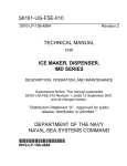
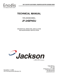
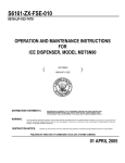
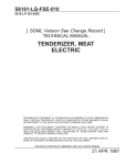
S6161-MX-FSE-010
TECHNCIAL MANUAL
OPERATION AND SERVICE MANUAL
MODEL NUMBER 56319
WELL, HOT FOOD STORAGE, ELECTRIC
DISTRIBUTION STATEMENT B: DISTRIBUTION AUTHORIZED TO U.S. GOVERNMENT AGENCIES ONLY;
ADMINISTRATIVE/ OPERATIVE USE. OTHER REQUESTS FOR THIS DOCUMENT MUST BE REFERRED TO
NAVAL SEA SYSTEMS COMMAND (PMS325).
WARNING: THIS DOCUMENT CONTAINS TECHNICAL DATA WHOSE EXPORT IS RESTRICTED BY THE
ARMS EXPORT CONTROL ACT (TITLE 22, U.S.C. SEC. 2751 ET SEQ.) OR THE EXPORT ADMINISTRATION
ACT OF 1979, AS AMENDED, TITLE 50, U.S.C, APP 2401, ET SEQ. VIOLATIONS OF THESE EXPORT LAWS
ARE SUBJECT TO SEVERE CRIMINAL PENALTIES. DISSEMINATE IN ACCORDANCE WITH PROVISIONS
OF OPNAVINST 5510.161, REFERENCE (JJ).
DESTRUCTION NOTICE: DESTROY BY ANY METHOD THAT WILL PREVENT DISCLOSURE OF CONTENTS
OR RECONSTRUCTION OF THE DOCUMENT.
PUBLISHED BY DIRECTION OF COMMANDER, NAVAL SEA SYSTEMS COMMAND
*0910LP1528400*
TITLE-1 / (TITLE-2 Blank)@@FIpgtype@@TITLE@@!FIpgtype@@
@@FIpgtype@@TITLE@@!FIpgtype@@
TITLE-2
@@FIpgtype@@BLANK@@!FIpgtype@@
S6161-MX-FSE-010
CHANGE RECORD
CHANGE NO.
DESCRIPTION OF CHANGE
CHANGE DATE
CHANGE RECORD-1 / (CHANGE RECORD-2 Blank)
CHANGE RECORD-2
@@FIpgtype@@BLANK@@!FIpgtype@@
S6161-MX-FSE-010
TABLE OF CONTENTS
Chapter/Paragraph
Page
OWNERS INFORMATION:
. . . . . . . . . . . . . . . . . . . . . . . . . . . . . . .
1-1
. . . . . . . . . . . . . . . . . . . . . . . . . . . . . . . . . . . . . . .
1-1
DRY HEATING: . . . . . . . . . . . . . . . . . . . . . . . . . . . . . . . . . . . . . .
1-1
STEAM HEATING: . . . . . . . . . . . . . . . . . . . . . . . . . . . . . . . . . . . .
1-1
HOT WATER HEATING: . . . . . . . . . . . . . . . . . . . . . . . . . . . . . . . . .
1-1
THERMOSTAT: . . . . . . . . . . . . . . . . . . . . . . . . . . . . . . . . . . . . . .
1-2
SHUTDOWN:
. . . . . . . . . . . . . . . . . . . . . . . . . . . . . . . . . . . . . . .
1-2
MAINTENANCE INSTRUCTIONS: . . . . . . . . . . . . . . . . . . . . . . . . . . .
1-2
TROUBLESHOOTING: . . . . . . . . . . . . . . . . . . . . . . . . . . . . . . . . . .
1-3
TROUBLE SHOOTING GUIDE . . . . . . . . . . . . . . . . . . . . . . . . . . . . .
1-3
HEATING UNIT DIAGNOSTICS: . . . . . . . . . . . . . . . . . . . . . . . . . . . .
TOOLS REQUIRED: . . . . . . . . . . . . . . . . . . . . . . . . . . . . . . .
1-4
1-4
DISASSEMBLY/REASSEMBLY OF HOT FOOD WELL:
. . . . . . . . . . . . . .
1-5
HEATER REPAIR/REPLACEMENT INSTRUCTIONS: . . . . . . . . . . . . . . . .
1-5
THERMOSTAT REPAIR/REPLACEMENT INSTRUCTIONS: . . . . . . . . . . . .
1-5
PILOT LIGHT REPAIR/REPLACEMENT INSTRUCTIONS: . . . . . . . . . . . . .
1-6
PACKAGING: . . . . . . . . . . . . . . . . . . . . . . . . . . . . . . . . . . . . . . .
1-6
RECEPTACLE MOUNTING - GENERAL: . . . . . . . . . . . . . . . . . . . . . . .
1-6
THERMOSTAT CONTROL PANEL:
. . . . . . . . . . . . . . . . . . . . . . . . . .
1-6
OPERATION AFTER INSTALLATION: . . . . . . . . . . . . . . . . . . . . . . . . .
1-7
ELECTRICAL CONNECTIONS: . . . . . . . . . . . . . . . . . . . . . . . . . . . . .
1-7
WARRANTY . . . . . . . . . . . . . . . . . . . . . . . . . . . . . . . . . . . . . . . .
1-14
OPERATION:
i
S6161-MX-FSE-010
LIST OF TABLES
Table
ii
Title
Page
S6161-MX-FSE-010
LIST OF ILLUSTRATIONS
Figure
Title
Page
1
WELL, HOT FOOD, STORAGE, ELECTRIC MODEL 56319 . . . . . . . . . . . .
1-8
2
COUNTER HOLE LAYOUT FOR MODEL 56319 . . . . . . . . . . . . . . . . . . .
1-9
3
TEMPLATE FOR STUD LOCATION ON CONTROL HOUSING . . . . . . . . . .
1-10
4
WIRING DIAGRAM
. . . . . . . . . . . . . . . . . . . . . . . . . . . . . . . . . . .
1-11
5
HEATING ELEMENT . . . . . . . . . . . . . . . . . . . . . . . . . . . . . . . . . . .
1-12
6
THERMOSTAT
1-13
. . . . . . . . . . . . . . . . . . . . . . . . . . . . . . . . . . . . . .
iii
S6161-MX-FSE-010
SAFETY SUMMARY
GENERAL SAFETY NOTICES The following general safety notices supplement the specific warnings
and cautions appearing elsewhere in this manual. They are recommended precautions that must be understood
and applied during operation and maintenance of the equipment covered herein. Should situations arise that are
not covered in the general or specific safety precautions, the commanding officer or other authority will issue
orders as deemed necessary to cover the situation.
DO NOT REPAIR OR ADJUST ALONE Under no circumstances should repairs or adjustment of energized equipment be attempted alone. The immediate presence of someone capable of rendering aid is required.
Before making adjustments, be sure to protected against grounding. If possible, adjustments should be made with
one hand, with the other hand free and clear of equipment.
TEST EQUIPMENT Make certain test equipment is in good condition. If a test meter must be held,
ground the case of the meter before starting measurement; do not touch live equipment or personnel working on
live equipment while holding a test meter. Some types of measuring devices should not be grounded; these
devices should not be held when taking measurements.
POWER SOURCE
Always disconnect power at power distribution source before servicing or replacing
parts.
BEFORE USING, BE SURE UNIT IS PROPERLY INSTALLED: SEALED
FOR WET USE. (Page 1-1)
BEFORE USING, BE SURE UNIT IS PROPERLY INSTALLED: SEALED
FOR ″WET″ USE. (Page 1-2)
BE SURE LINE SWITCH IS CLOSED BEFORE TURNING THERMOSTAT
CONTROL(S) ON WHEN EQUIPMENT IS TO BE USED. (Page 1-2)
ALTHOUGH YOUR FOOD WARMING RECEPTACLE IS MADE OF 302
STAINLESS STEEL, USE CARE DURING THE CLEANING OPERATION.
HEAVY OBJECTS MUST NOT BE DROPPED INTO THE RECEPTACLE.
(Page 1-3)
iv
S6161-MX-FSE-010
DISCONNECT AL POWER TO HOT FOOD WELL PRIOR TO MAINTENANCE. (Page 1-3)
DISCONNECT ALL POWER TO HOT FOOD WELLS PRIOR TO ANY
REPAIRS OR REPLACEMENT OF PARTS. (Page 1-3, page 1-5, page 1-5, page
1-6)
DISCONNECT ALL POWER TO THE TABLE BEFORE PERFORMING
ELECTRICAL MEASUREMENTS WITH AN OHMMETER. (Page 1-4)
Service personnel authorized to evaluate an individual unit not performing properly should first check voltage levels at the power source, using a voltmeter in
accordance with accepted practices. (Page 1-4)
DISCONNECT ALL POWER TO THE WELL BEFORE PERFORMING
ELECTRICAL MEASUREMENTS WITH AN OHMMETER. (Page 1-4)
DEVICE MUST BE GROUNDED IN ACCORDANCE WITH REQUIREMENTS OF THE NATIONAL ELECTRICAL CODE OR APPLICABLE
LOCAL CODES. (Page 1-7)
v
S6161-MX-FSE-010
OPERATION AND SERVICE MANUAL WELL, HOT FOOD STORAGE, ELECTRIC
PER: MIL-W-43896-A
27 DECEMBER 1983
CONTRACT NO: DLA400-07-C-2744
NSN: 7310-01-206-1081
WELL, HOT FOOD STORAGE, ELECTRIC
VOLTAGE: 115 VOLTS, 60 CYCLES, SINGLE PHASE
WATTS: 1500
AMPS: 13
MODEL NO: 56319
APPROVED: 16 NOV 88
vi
S6161-MX-FSE-010
CHAPTER 1
OWNERS INFORMATION:
Steam table odor and wasted heat are reduced in your new food warming receptacle. Used either wet (if
receptacle has been sealed) or dry, the stainless steel receptacle is insulated on all sides to keep the top of your
hot food table cool and save power. A single thermostat control and signal light can be mounted in any convenient location or grouped into a control panel with other receptacle controls. The thermostat dial provides a complete range of settings for holding foods at the most desirable serving temperatures. For fast and convenient
replacement, a single heating unit is clamped to the bottom of the receptacle.
OPERATION:
Since your food warming receptacle is designed for warming or holding pre-cooked food, it will not overcook food when properly used. There are three ways of maintaining hot food in the receptacle: dry heating, steam
heating, or hot water heating.
DRY HEATING:
1. With the control at Number 10 position, allow the receptacle to preheat, covered for 60 minutes.
2. Place food in inserts or pans; place inserts or pans in receptacle. Set control at the position that keeps the food
at your desired temperature. Keep the food covered when not serving.
STEAM HEATING:
1. Place a few quarts of cold water or hot water (for faster preheat) into the receptacle.
2. To preheat set the thermostat to Position 10 and cover the receptacle with a food pan or other cover until water
boils.
3. Place food in inserts or pans and place inserts or pans in receptacle. Keep the food covered when not serving. Adjust the thermostat to any desired degrees after boiling is achieved.
BEFORE USING, BE SURE UNIT IS PROPERLY INSTALLED: SEALED
FOR WET USE.
HOT WATER HEATING:
1. Fill the receptacle with hot water to a depth so that the food container is in contact with the water.
2. Set the thermostat to Position 10 and cover the receptacle with a food pan until the water boils.
3. Place food in inserts or pans and place inserts or pans in receptacle. Keep the food covered when not serving. Adjust the thermostat to any desired degrees after boiling is achieved.
1-1
S6161-MX-FSE-010
WITH STEAM AND HOT WATER HEATING, THE DRYING OF FOOD IS
MINIMIZED BECAUSE THE ESCAPING WATER VAPOR FROM THE
RECEPTACLE CREATES HUMID AIR OVER THE FOOD.
BEFORE USING, BE SURE UNIT IS PROPERLY INSTALLED: SEALED
FOR ″WET″ USE.
THERMOSTAT:
The steel, zinc-trim plated thermostat bulb is clamped to the underside base of the receptacle. A capillary tube
extends to the thermostat control. Whenever the heating unit is energized, the pilot light glows and goes off when
the preset temperature is reached. The cycling of the thermostat is therefore indicated by the signal light.
SHUTDOWN:
At the end of the day or food serving period, turn the thermostat control(s) to the OFF position. This removes
all power to the unit(s). To shut off the equipment for long periods of time or prevent unauthorized use, open the
line switch that controls the power to the hot food well(s).
BE SURE LINE SWITCH IS CLOSED BEFORE TURNING THERMOSTAT
CONTROL(S) ON WHEN EQUIPMENT IS TO BE USED.
MAINTENANCE INSTRUCTIONS:
When the food warming receptacle is used dry, food spillage on the hot surfaces will burn and stick. The
same commercial cleaners used on your stainless steel kitchen utensils may be used to clean the receptacle. Wash
the interior surfaces with water and a detergent to remove mild discolorations. Rinse with plain water and dry
with an absorbent cloth.
The bottom of the receptacle may take on a straw-colored appearance when used dry. This is due to the heat,
which causes the stainless steel to discolor. This discoloration will not come off with normal cleaning procedures,
but it poses no problem.
1-2
S6161-MX-FSE-010
ALTHOUGH YOUR FOOD WARMING RECEPTACLE IS MADE OF 302
STAINLESS STEEL, USE CARE DURING THE CLEANING OPERATION.
HEAVY OBJECTS MUST NOT BE DROPPED INTO THE RECEPTACLE.
If your food warming receptacle is used wet, all surfaces are covered with a film of water. Food spillage into
the receptacle will not stick or carbonize, but will drop into the water and float or settle to the bottom. To clean
the receptacle, remove the water with a suitable container and sponge out the rest. Wash the receptacle with a
detergent and hot water, rinse, and dry.
To clean the thermostat knob, pull it outward to remove it from the shaft. Wash the knob with a mild soap
and water, rinse, and dry with a soft cloth. Do not use abrasive cleaners on the plastic surface.
DISCONNECT AL POWER TO HOT FOOD WELL PRIOR TO MAINTENANCE.
TROUBLESHOOTING:
Permanently installed in the hot food serving table, the food warming receptacle(s) consists of a rectangular
stainless steel hot food well. A single heating unit is clamped to the underside of the receptacle, which is controlled by a separately mounted thermostat. When the thermostat is turned from the OFF position, the signal light
comes on and the heating unit is energized. Upon reaching the desired temperature, the thermostat opens the circuit, the signal light goes off, and the heating unit is de-energized. This cycle is repeated automatically whenever
the thermostat is turned ON.
Electrically, your food warming receptacle is a relatively simple device designed for many years of trouble
free service. If the unit does not heat when the thermostat is turned from the OFF position, check for an open
power switch or burned out fuse. Continued in-operation would indicate possible troubles in the thermostat or
heating unit. If the unit heats properly but the pilot light does not come on, this indicates a burned out lamp,
which should be replaced.
DISCONNECT ALL POWER TO HOT FOOD WELLS PRIOR TO ANY
REPAIRS OR REPLACEMENT OF PARTS.
TROUBLE SHOOTING GUIDE
SYMPTOM
No heat
LIKELY CAUSE
1. Thermostat defective
2. Heater open
3. Heater grounded
SUGGESTION ACTION
1. Measure voltage across thermostat connections
2. Measure beater lead resistance
3. Measure heater lead resistance
1-3
S6161-MX-FSE-010
SYMPTOM
Not enough heat
No pilot light
LIKELY CAUSE
4. No power
1. Thermostat calibration
1. Bulb burned out
SUGGESTION ACTION
4. Measure source voltage
1. Recalibrate
2. Check for continuity with ohmmeter
DISCONNECT ALL POWER TO THE TABLE BEFORE PERFORMING
ELECTRICAL MEASUREMENTS WITH AN OHMMETER.
HEATING UNIT DIAGNOSTICS:
TOOLS REQUIRED: Voltmeter, thermometer, small blade (.125 inch, .32 cm) long shaft slotted screwdriver,
and acceptable instrument grade, non-toxic residue solvent and glue for shaft adjustments.
Service personnel authorized to evaluate an individual unit not performing properly should first check voltage levels at the power source, using a voltmeter in
accordance with accepted practices.
If a well fails to reach the final temperatures, the likely causes are a malfunctioning heater or thermostat,
assuming all connections are secure within the table.
1. Unit circuit resistance should be 9.6 ohms measured with an ohmmeter at the heater wires labelled H1 and
H2. An infinite reading indicates a break in the heater’s resistance wire. A low or short reading between either
H1 or H2 and any part of the unit chassis indicates failed circuit integrity. If the unit circiut resistance fails
to be 9.6 ohms, replace the Heater and heater lead wiring. Directions are provided below.
2. Unit circuit resistance readings taken with an ohmmeter across the line terminals for a good reading at ″off″
should be infinite. When the thermostat shaft is turned to an ″on″ position, a ohms reading should result,
assuming step 1 indicated a normal heater resistance. If the thermostat, acting as a switch, fails to yield a normal reading past the number ″5″ position, the thermostat should be replaced.
DISCONNECT ALL POWER TO THE WELL BEFORE PERFORMING
ELECTRICAL MEASUREMENTS WITH AN OHMMETER.
1-4
S6161-MX-FSE-010
DISASSEMBLY/REASSEMBLY OF HOT FOOD WELL:
HEATER REPAIR/REPLACEMENT INSTRUCTIONS:
STEP 1: Separate the thermostat control housing (which is tied by its capillary tube into the heated zone) from
the cabinet by removing and retaining the pilot light and hardware.
STEP 2: Disconnect and label the input power leads coming from the contactor output. Disconnect the drain
line’s two uppermost unions from the well drain lines to separate the well from the manifold plumbing.
STEP 3:
A. Using a slotted screwdriver or 1/4 inch socket wrench, remove and retain the 8 screws and bottom
inspection plate.
B. Remove and retain the six 3/8 inch sheet metal nuts securing the reflector pan to the well receptacle bottom. Remove the reflector pan with heater, heater leads and ground plus capillary bulb
away from the well. Unscrew the two heater lugs and retain the screws. Using pliers, bend tabs
holding the heater to the reflector to free the heater.
C. Clamp new heating element to the reflector pan using pliers to reform the tabs holding the element
and reverse parts (c) through (a) of step 3 as well as steps 2 and 1 described above.
DISCONNECT ALL POWER TO HOT FOOD WELLS PRIOR TO ANY
REPAIRS OR REPLACEMENT OF PARTS.
THERMOSTAT REPAIR/REPLACEMENT INSTRUCTIONS:
1. Repeat step 1 and step 3 (a) described above for HEATER REPLACEMENT to expose the capillary bulb and
the rejecter pan. Using pliers, deflect the two crimp tabs clamping the bulb to the reflector pan to loosen the
bulb
2. Pull the capillary and thermostat housing out of the heated well assembly. Route a replacement thermostat
housing into the well assembly along the path followed by the original thermostat and using pliers, secure the
capillary bulb to the reflector pan.
3. Reverse step 3 and step 1 for HEATER REPLACEMENT.
DISCONNECT ALL POWER TO HOT FOOD WELLS PRIOR TO ANY
REPAIRS OR REPLACEMENT OF PARTS.
1-5
S6161-MX-FSE-010
PILOT LIGHT REPAIR/REPLACEMENT INSTRUCTIONS:
1. Remove front control panel held in by four screws. Separate panel from front of counter. Squeeze the barrel
tabs of the snap-in-place pilot light from behind panel to separate the lamp from the bezel and disconnect the
lamp lens.
2. Install new pilot light and reverse the steps of 1 above.
DISCONNECT ALL POWER TO HOT FOOD WELLS PRIOR TO ANY
REPAIRS OR REPLACEMENT OF PARTS.
PACKAGING:
Each food warming receptacle is shipped completely assembled with insulation, heating unit, and thermostat
control box. Two wires and thermostat capillary tube are provided so that the control can be mounted in any convenient location. Inspect the unit for possible damage during shipment.
RECEPTACLE MOUNTING - GENERAL:
The deep drawn, single piece stainless steel pan is recessed in an opening 13 1/2″ by 21-3/8″ in the table top.
It is held in position by machine screws around the upper edge of the receptacle. For multiple installations, the
receptacles are separated by at least 4 1/4″ of space and are mounted at least 4″ from the front wall of the table.
The receptacle is mounted on the underside of metal table top, using hardware supplied. When cutting openings in the table top for multiple receptacles, leave at least 4 1/4″ separation between openings and at least 4″
between each opening and the front wall of the table.
The receptacle is insulated on all four sides and the bottom. A cover is held in place by (8) hex sheet metal
screws on the bottom of the receptacle. It can be quickly removed to provide access to the heating unit and thermostat control bulb. This cover also supports the insulation around the sides and bottom of the receptacle.
The customer or cabinet fabricator must furnish the metal cabinet, metal field wiring compartment for each
receptacle, the wire raceway, the cabinet disconnect switch and/or overcurrent protection device, cabinet supply
conductors and other small electrical hardware. Factors which influence the sizing of the cabinet supply conductors are the maximum current draw per wire, the wire material, the wire temperature rating and the applicable
electrical codes both national and local. Since the maximum value of the overcurrent protection device is limited
to 50 amperes per cabinet (branch) line wire, the maximum useful current draw is limited to 37.5 to 40 amperes
which limits the quantity of receptacles that can be connected to the same cabinet line wire.
THERMOSTAT CONTROL PANEL:
The thermostat control panel can be mounted in any convenient location withing 24″ from the receptacle.
Drilling and hole dimensions are shown in Illustration #2. To prevent damage to the capillary tube, coil the excess
length around a 2″ diameter object in the form of a coil. Store it behind the thermostat in a convenient location
away from the electrical connections on the control. Avoid sharp bends.
1-6
S6161-MX-FSE-010
OPERATION AFTER INSTALLATION:
Turn the thermostat to any position other than OFF. The heating unit should energize and the pilot light
should now glow. After the preheat period, the thermostat contacts open and the power is removed from the heating unit. The pilot light then goes off. Check several heat cycles with the thermostat in different positions to make
sure the equipment is operating properly.
ELECTRICAL CONNECTIONS:
Each receptacle is furnished with high temperature, nickel stranded conductors between the heating unit and
thermostat and/or the cabinet supply lines. The size of the stranded nickel for a 115 volt receptacle is 12 AWG
and for a 208 or 230 volt receptacle is 14 AWG. There is a 6″ long pigtail of 14 AWG copper wire on one terminal of the thermostat for making connection to one of the cabinet hot supply lines (normally the line conductor has a black covering) and never the grounded neutral end (normally the line conductor has a white or gray
covering). Since the nickel-stranded wire is sized for the load of a single receptacle, it must not be used for the
wiring of the cabinet supply lines. THE QUANTITY OF RECEPTACLE CONNECTED TO ANY ONE LINE
FOR SINGLE PHASE OR ANY TWO LINES FOR THREE PHASE MUST NOT REQUIRE THE OVERCURRENT PROTECTIVE DEVICE IN THOSE LINES TO EXCEED 50 AMPS.
DEVICE MUST BE GROUNDED IN ACCORDANCE WITH REQUIREMENTS OF THE NATIONAL ELECTRICAL CODE OR APPLICABLE
LOCAL CODES.
SPARE PARTS LIST - MODEL 56319
ITEM NUMBER
PART NUMBER
1
2
3
4
5
6
56321
56322
56527
56528
56530
56370
DESCRIPTION
Stainless steel storage well
Heater coil
Thermostat
Thermostat knob
Pilot light
Control panel
QUANTITY
EACH ASSY.
1
1
1
1
1
1
ADDRESSES OF VENDORS FOR PARTS
American Permanent Ware Co.
729 Third Avenue
Dallas, Texas 75226
1-7
S6161-MX-FSE-010
Figure 1 WELL, HOT FOOD, STORAGE, ELECTRIC MODEL 56319
1-8
S6161-MX-FSE-010
1-9
Figure 2 COUNTER HOLE LAYOUT FOR MODEL 56319
S6161-MX-FSE-010
Figure 3 TEMPLATE FOR STUD LOCATION ON CONTROL HOUSING
1-10
Figure 4 WIRING DIAGRAM
S6161-MX-FSE-010
1-11
S6161-MX-FSE-010
1-12
Figure 5 HEATING ELEMENT
Figure 6 THERMOSTAT
S6161-MX-FSE-010
1-13
S6161-MX-FSE-010
WARRANTY
We warrant to the purchaser of each new Food Warmer that any part thereof which proves to be defective in
material or workmanship within one year from the date of original purchase, will be repaired or replaced free of
charge.
Any defect in such an appliance should be brought to the attention of the company from whom it was purchased, who will be authorized to furnish or arrange for repairs or replacement within the terms of this warranty.
This warranty is expressly in lieu of all other warranties, express or implied, and we neither assume nor
authorize any person to assume for us any other obligation or liability in connection with said appliance. This
warranty does not apply, and no warranty either express or implied shall be applicable to:
1: Damage resulting from accident, alteration, misuse or abuse.
2: If the serial number affixed to the appliance by the manufacturer shall be removed, obliterated or defaced.
1-14
Ref: NAVSEAINST 4160.3 NAVSEA S0005-AA-GYD-030/TMMP
NAVSEA/SPAWAR TECHNICAL MANUAL DEFICIENCY/EVALUATION REPORT (TMDER)
INSTRUCTIONS: Continue on 8 ½” x 11” on page if additional space is needed.
1. Use this report to indicate deficiencies, problems and recommendations relating to publications.
2. For CLASSIFIED TMDERs see OPNAVINST 5510H for mailing requirements.
3. For TMDERs that affect more than one publication, submit a separate TMDER for each.
4. Submit TMDERs at web site https://nsdsa.nmci.navy.mil or mail to: COMMANDER, CODE 310 TMDERs, NAVSURFWARCENDIV
NSDSA, 4363 MISSILE WAY BLDG 1389, PORT HUENEME CA 93043-4307
1. PUBLICATION NUMBER
2. VOL/PART
3. REV/DATE OR CHG/DATE
5. TITLE OF PUBLICATION
4. SYSTEM/EQUIPMENT ID
6. REPORT CONTROL NUMBER
(6 digit UIC-YY-any four: xxxxxx-10-xxxx)
7. RECOMMEND CHANGES TO PUBLICATION
7a. Page #
7b. Para #
7c. RECOMMENDED CHANGES AND REASONS
8. ORIGINATOR’S NAME AND WORK CENTER
9. DATE
10. ORIGINATOR’S E-MAIL ADDRESS
11. TMMA of Manual
(NSDSA will complete)
12. SHIP OR ACTIVITY Name and Address (Include UIC/CAGE/HULL)
13. Phone Numbers:
Commercial
(
)
FAX
NAVSEA 4160/1 (Rev. 9-2010)
S/N 0116-LF-985-4100
-
DSN
(
)
-
FOLD HERE AND TAPE SECURELY
PLEASE DO NOT STAPLE
INCLUDE COMPLETE ADDRESS
USE
PROPER
POSTAGE
FOR OFFICIAL USE ONLY
COMMANDER
CODE 310 TMDERs
NAVSURFWARCENDIV NSDSA
4363 MISSILE WAY BLDG 1389
PORT HUENEME CA 93043-4307
FOLD HERE AND TAPE SECURELY
PLEASE DO NOT STAPLE
blank back cover.
S6161-MX-FSE-010