1
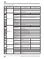
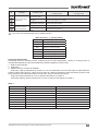
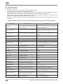
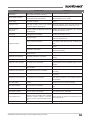
No.
Message
G1
G2
Possible solution
in heating mode
Probable cause
Frost in compressor
suction line
Expansion valve does
not work properly.
Refrigerant filter
clogged.
Check and replace if necessary.
Check and replace if necessary.
G3
Evaporator obstructed.
Clean evaporator surface.
H1
Components vibrate.
The compressor is
noisy.
Fasten properly.
H2
Abnormal noises in
heat pump system
Possible solution
in cooling mode
Replace the compressor.
– the cause must be eliminated only by qualified person.
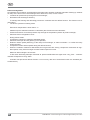
Table of terms, [...] - factory setting
BLDC
Inverter compressor
ON/OFF
Fixed speed compressor
Req_min
Minimum request signal
EXV
Electornic expansion valve
EVD
Electronic valve driver
MOP
Maximum operating pressure
LOP
Lowest operating pressure
SH
Superheating
Heat pump management
Heat pump built-in air handling unit are controlled by air set point temperature. Heating or cooling function is
activated automatically by set point and demand. Default temperature control order:
1. Rotary heat exchanger;
2. Heat pump;
3. Additional cooler or heater (if installed).
Heat pump capacity depends from air flow. It‘s not recommended to use units with high air flows difference
between supply and extract air. If there are more than 20 % difference between supply and extract air flows, heat
pump efficiency and capacity decreases or heat pump may not work properly at all.
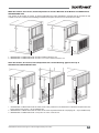
Heat pump will be switched off if one (or both) air flow will be as in table 1;
Heat pump capacity will be reduced to 60 % if one (or both) air flow will be as in table 1;
Table 1
Unit size
Air flow when heat pump switched off [m3/h]
Air flow when heat pump capacity are limited [m3/h]
10
900
1200
20
1800
2400
30
2700
3600
40
3600
4800
50
5000
7000
60
7000
9000
70
9000
12000
80
10000
14000
90
13000
16000
UAB AMALVA reserves the right to make changes without prior notice
21