1
Chapter 23
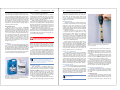
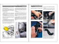
Attach the flushing gun to the top water outlet of the
block. Attach a lead-away hose to the bottom outlet, if necessary. Reverse-flush the block using the procedure described
for the radiator. See Figure 23-7B. After flushing, reattach all
hoses securely. Fill the system with water and add antifreeze
or inhibitor as needed. Finally, test the system for leaks.
Reverse Flushing the Heater Core
After determining the direction of coolant flow, remove
the heater hoses from the engine block. Be sure to remove the
heater shut-off valve (if used) from the system before beginning the flushing procedure. To reverse flush the heater core,
follow the procedures presented in the section on reverse
flushing a radiator.
Note: Some heater systems cannot be reverse
flushed. Check the manufacturer’s
recommendations.
After flushing, reconnect the heater hoses and reinstall
the heater shutoff valve. Refill the cooling system and test it
for leaks.
Finding Leaks in the Cooling System
Cooling system leaks can develop over time. They can
be caused by corrosion, vibration, or the gradual loosening of
system fittings. Sometimes, cleaning may open cracks or
other tiny openings that had been sealed with rust. Removing
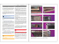
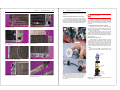
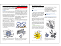
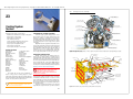
of the rust allows leaking to start. Figure 23-8 shows typical
examples of radiator damage.
Coolant leakage can cause engine overheating and
damage to the pistons, valves, and cylinder head. If coolant
leaks into the cylinders, it may plug the rings and cause hard
starting, excessive oil consumption, piston corrosion, and
bearing failure. Combustion gas leakage into the cooling
system can cause overheating and severe cooling system
corrosion. Any time the cooling system loses water and an
obvious leak cannot be found, the system should be pressure
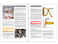
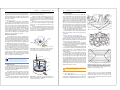
tested, Figure 23-9, or checked with special chemicals or a
black light.
Pressure Testing the Cooling System
Pressurizing the cooling system raises the boiling point
of the coolant mixture. This allows the engine to operate at
higher temperatures without causing the coolant to boil. Hotter
temperatures increase combustion efficiency, resulting in
more power, better mileage, and lower emissions.
Caution: Some of the newest systems use
pressures up to 25 psi (172 kPa). Special pressure
testers must be used on these systems. Do not
pressurize older systems past 20 psi (137 kPa). Higher
pressure could cause the radiator, heater core, or other
components to rupture.
Cooling System Service
459
Fill the radiator to within 1/2″ (12.7mm) of the filler neck.
Attach the pressure tester to the filler neck, Figure 23-9A.
Build up pressure in the system carefully; do not exceed the
pressure for which the system is designed. Check the pressure marking on the radiator cap or obtain information from
the manufacturer’s manual.
When the system is pressurized, watch the gauge. If the
pressure holds steady, the system is probably all right. If the
pressure drops, carefully check all areas for leaks. Even a
small amount of dampness indicates enough loss of coolant
to cause trouble. If no leak can be found, check the tester
connection to the filler neck to make certain it is not leaking.
Occasionally, you will find a system that leaks only when
cold or when hot. By checking the system before and after
engine warm-up, both types of leaks will be exposed. When
finished with the pressure test, adjust coolant to the proper
level in the radiator.
Radiator Pressure Caps
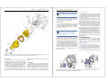
Cooling systems are pressurized by using a radiator
pressure cap. The pressure cap contains a spring that will
not allow pressure to escape from the system until a certain
level is reached.
The boiling point of the coolant is raised about 3°F
(1.6°C) for each pound of pressure added. If pressure buildup
permitted by the radiator cap is 15 psi (103 kPa), the boiling
point of the coolant under pressure will be increased by 45°F
(15 x 3°F). At sea level, water boils at 212°F (100°C). Adding
45°F to 212°F gives us 257°F, the temperature at which radiator coolant will boil when under 15 psi (103 kPa) of pressure.
To maintain specified pressure, the cap pressure valve spring
and seal surface must be in good condition.
460
Auto Diagnosis, Service, and Repair
Solder bloom—Solder corrosion caused by degradation of
antifreeze rust inhibitors. Tube-to-header joints are weakened
and corrosion can restrict coolant flow.
Internal deposits—Rust and leak inhibitors (Stop-leak) can
form solids that collect in the cooling system and restrict flow.
Tube-to-header-leaks—Solder joint failure resulting in coolant
loss.
Leaky tank-to-header seam—Solder joint failure or a cracked
header, usually the result of pressure-cycle fatigue.
Leaky oil cooler—Coolant shows traces of oil. Transmission/
transaxle or engine damage can result.
Leaky inlet/outlet fitting—Leaks in this area can be caused
by fatigue or solder joint corrosion.
Electrolysis—Electrical current created by the chemical
reaction between coolant and two dissimilar metals. Causes
corrosion of metal components.
Electrolysis—Electrical current created by the chemical
reaction between coolant and two dissimilar metals. Will
produce voids in tubes.
Pressure Cap Testing
Cap operation can be checked by using a pressure
tester, Figures 23-9B and 23-9C. Always place a protective
rag over the cap during removal. Stand to one side. Open the
cap to the safety stop and wait for steam pressure to subside.
The cap may then be safely removed.
Warning: Removing a pressure cap from a hot
radiator can be very dangerous. Sudden release of
the pressure may cause the water to turn to steam
and literally “explode” into the face of the person removing
the cap.
Install the adapter on the tester, then install the cap and
perform the pressure test. The cap should retain a pressure
within 1 1/2 psi (10 kPa) of its specified pressure rating. If the
cap fails to pass the test, replace it with a new cap of the
correct pressure rating. Do not use a nonpressure cap on a
pressurized system. Do not use a cap designed for an open
system (no coolant reservoir) on a closed system (coolant
recovery reservoir).
If the cap tests OK, remove the tester. Loosely install
the radiator cap and run the engine until normal temperature
is reached. Remove the cap, attach the pressure pump,
Figure 23-8. Radiator failures are common. These are some you are likely to see. (Modine)