1
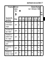
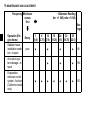
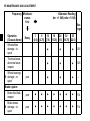
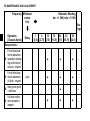
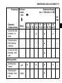
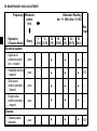
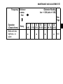
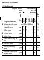
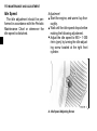
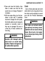
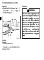
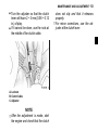
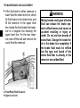
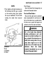
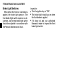
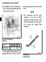
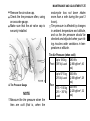
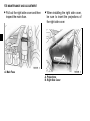
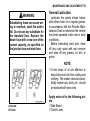
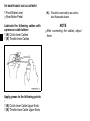
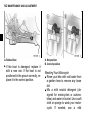
MAINTENANCE AND ADJUSTMENT 71
MAINTENANCE AND ADJUSTMENT
The maintenance and adjustments outlined in this chapter must be carried out
and must be done in accordance with the Periodic Maintenance Chart to keep the
motorcycle in good running condition. The initial maintenance is vitally important and must not be neglected.
With a basic knowledge of mechanics and the proper use of tools, you should be
able to carry out many of the maintenance items described in this chapter. If you
lack proper experience or doubt your ability, all adjustments, maintenance, and repair work should be completed by a qualified technician.
Please note that Kawasaki cannot assume any responsibility for damage resulting from incorrect or improper adjustment done by the owner.
72 MAINTENANCE AND ADJUSTMENT
EMISSION CONTROL INFORMATION
To protect the environment in which we all live, Kawasaki has incorporated
crankcase emission (1) and exhaust emission (2) control systems in compliance
with applicable regulations of the United States Environmental Protection Agency
and California Air Resources Board. Additionally, Kawasaki has incorporated an
evaporative emission control system (3) in compliance with applicable regulations
of the United States Environmental Protection Agency.
1. Crankcase Emission Control System
This system eliminates the release of crankcase vapors into the atmosphere.
Instead, the vapors are routed through an oil separator to the intake side of the
engine. While the engine is operating, the vapors are drawn into the combustion
chamber, where they are burned along with the fuel and air supplied by the fuel
injection system.
2. Exhaust Emission Control System
This system reduces the amount of pollutants discharged into the atmosphere
by the exhaust of this motorcycle. The fuel, ignition and exhaust systems of this
motorcycle have been carefully designed and constructed to ensure an efficient
engine with low exhaust pollutant levels. The exhaust system of this model motorcycle includes a catalytic converter system.
MAINTENANCE AND ADJUSTMENT 73
3. Evaporative Emission Control System
The evaporative emission control system for this vehicle consists of low permeation fuel hoses and a fuel tank.
3. Evaporative Emission Control System (California)
Vapors caused by fuel evaporation in the fuel system are not vented into the atmosphere. Instead, fuel vapors are routed into the running engine to be burned, or
stored in a canister when the engine is stopped. Liquid fuel is caught by a vapor
separator and returned to the fuel tank.
High Altitude Performance Adjustment Information
High altitude adjustment is not required.
74 MAINTENANCE AND ADJUSTMENT
MAINTENANCE AND WARRANTY
Proper maintenance is necessary to ensure that your motorcycle will continue to
have low emission levels. This Owner's Manual contains those maintenance recommendations for your motorcycle. Those items identified by the Periodic Maintenance Chart are necessary to ensure compliance with the applicable standards.
As the owner of this motorcycle, you have the responsibility to make sure that
the recommended maintenance is carried out according to the instructions in this
Owner's Manual at your own expense.
The Kawasaki Limited Emission Control System Warranty requires that you return your motorcycle to an authorized Kawasaki dealer for remedy under warranty.
Please read the warranty carefully, and keep it valid by complying with the owner's
obligations it contains.
You should keep a maintenance record for your motorcycle. To assist you in
keeping this record, we have provided space on pages 160 through 165 of this
manual where an authorized Kawasaki dealer, or someone equally competent, can
record the maintenance. You should also retain copies of maintenance work orders, bills, etc., as verification of this maintenance.
MAINTENANCE AND ADJUSTMENT 75
TAMPERING WITH NOISE CONTROL SYSTEM PROHIBITED:
Federal law prohibits the following acts or the causing thereof: (1) the removal or
rendering inoperative by any person other than for purposes of maintenance, repair, or replacement, of any device or element of design incorporated into any new
vehicle for the purpose of noise control prior to its sale or delivery to the ultimate
purchaser or while it is in use, or (2) the use of the vehicle after such device or element of design has been removed or rendered inoperative by any person.
Among those acts presumed to constitute tampering are the acts listed below:
Replacement of the original exhaust system or muffler with a component not in
compliance with Federal regulations.
* Removal of the muffler(s) or any internal portion of the muffler(s).
* Removal of the air box or air box cover.
* Modifications to the muffler(s) or air intake system by cutting, drilling, or other
means if such modifications result in increased noise levels.
*
76 MAINTENANCE AND ADJUSTMENT
Periodic Maintenance Chart
K : Should be serviced by an authorized Kawasaki dealer.
* : For higher odometer readings, repeat at the frequency interval established here.
# : Service more frequently when operating in severe conditions: dusty, wet, muddy, high
speed, or frequent starting/stopping.
1. Periodic Inspection (Engine Related Items)
Frequency Whichever
comes
first
Operation (Engine Items)
Valve clearance inspect
Throttle control
system (play,
smooth return,
no drag) - inspect
Idle speed - inspect
Every
*Odometer Reading
km × 1 000 (mile × 1 000)
See
Page
1
6
12
18
24
30
36
(0.6) (3.75) (7.5) (11.25) (15) (18.75) (22.5)
•
year
104
•
•
•
•
107
•
•
•
•
110
MAINTENANCE AND ADJUSTMENT 77
Frequency Whichever
comes
first
Operation (Engine Items)
Fuel leak (fuel
K hose and pipe) inspect
K
Every
*Odometer Reading
km × 1 000 (mile × 1 000)
See
Page
1
6
12
18
24
30
36
(0.6) (3.75) (7.5) (11.25) (15) (18.75) (22.5)
year
•
•
•
•
–
year
•
•
•
•
–
year
•
•
•
•
–
Coolant leak - inspect
year
Radiator hose
damage - inspect
year
•
•
•
•
•
•
•
•
•
•
•
•
Fuel hoses damage - inspect
Fuel hoses inK stallation condition - inspect
Coolant level - inspect
99
–
96
78 MAINTENANCE AND ADJUSTMENT
Frequency Whichever
comes
first
Operation (Engine Items)
Radiator hoses
installation condition - inspect
Every
year
*Odometer Reading
km × 1 000 (mile × 1 000)
See
Page
1
6
12
18
24
30
36
(0.6) (3.75) (7.5) (11.25) (15) (18.75) (22.5)
•
Air suction system damage - inspect
Evaporative
emission control
system - function
(California model
only)
•
•
•
•
•
96
•
•
•
104
•
103
•
•
•
•
MAINTENANCE AND ADJUSTMENT 79
2. Periodic Inspection (Chassis Related Items)
Frequency Whichever
comes
first
Operation
(Chassis Items)
Clutch and drive
train:
Every
Clutch operation
(play, engagement, disengagement) inspect
K
Drive belt deflection - inspect
K
Drive belt wear inspect
*Odometer Reading
km × 1 000 (mile × 1 000)
See
Page
1
6
12
18
24
30
36
(0.6) (3.75) (7.5) (11.25) (15) (18.75) (22.5)
•
•
•
•
•
•
•
•
•
•
•
•
•
•
•
•
•
•
111
102
102
Wheels and tires:
Tire air pressure
- inspect
year
•
•
•
124
80 MAINTENANCE AND ADJUSTMENT
Frequency Whichever
comes
first
Operation
(Chassis Items)
Wheels/tires
damage - inspect
Every
*Odometer Reading
km × 1 000 (mile × 1 000)
See
Page
1
6
12
18
24
30
36
(0.6) (3.75) (7.5) (11.25) (15) (18.75) (22.5)
Tire tread wear,
abnormal wear inspect
Wheel bearings
K damage - inspect
year
•
•
•
126
•
•
•
126
•
•
•
–
Brake system:
Brake fluid leak inspect
Brake hoses
K damage - inspect
year
•
•
•
•
•
•
•
114
year
•
•
•
•
•
•
•
114
MAINTENANCE AND ADJUSTMENT 81
Frequency Whichever
comes
first
Operation
(Chassis Items)
Brake pad wear inspect #
Every
*Odometer Reading
km × 1 000 (mile × 1 000)
See
Page
1
6
12
18
24
30
36
(0.6) (3.75) (7.5) (11.25) (15) (18.75) (22.5)
•
•
•
•
•
•
114
•
•
•
•
•
•
•
114
Brake fluid level 6 month
inspect
•
•
•
•
•
•
•
115
Brake operation
(effectiveness,
play, drag) - inspect
•
•
•
•
•
•
•
117
•
•
•
•
•
•
•
118
Brake hose inK stallation condition - inspect
Brake light
switch operation
- inspect
year
year
82 MAINTENANCE AND ADJUSTMENT
Frequency Whichever
comes
first
Operation
(Chassis Items)
Suspensions:
Every
Front forks/rear
shock absorber
K operation (damping and smooth
stroke) - inspect
Front forks/rear
K shock absorber
oil leak - inspect
K
year
*Odometer Reading
km × 1 000 (mile × 1 000)
See
Page
1
6
12
18
24
30
36
(0.6) (3.75) (7.5) (11.25) (15) (18.75) (22.5)
•
•
•
–
•
•
•
–
•
Swing arm pivot
- lubricate
Uni-trak rocker
K arm operation inspect
•
•
–
•
–
MAINTENANCE AND ADJUSTMENT 83
Frequency Whichever
comes
first
Operation
(Chassis Items)
Uni-trak tie rods
K operation - inspect
Every
*Odometer Reading
km × 1 000 (mile × 1 000)
See
Page
1
6
12
18
24
30
36
(0.6) (3.75) (7.5) (11.25) (15) (18.75) (22.5)
•
•
•
–
Uni-trak rocker
K arm bearings lubricate
•
–
Uni-trak tie rods
K bearings - lubricate
•
–
Steering system:
K
Steering play inspect
Steering stem
K bearings - lubricate
year
2 years
•
•
•
•
•
–
–
84 MAINTENANCE AND ADJUSTMENT
Frequency Whichever
comes
first
Operation
(Chassis Items)
Electrical system:
Every
*Odometer Reading
km × 1 000 (mile × 1 000)
See
Page
1
6
12
18
24
30
36
(0.6) (3.75) (7.5) (11.25) (15) (18.75) (22.5)
Lights and
switches operation - inspect
year
•
•
•
–
Headlight aiming
- inspect
year
•
•
•
135
Side stand
switch operation
- inspect
year
•
•
•
–
Engine stop
switch operation
- inspect
year
•
•
•
–
year
•
•
•
139
Chassis:
Chassis parts lubricate
MAINTENANCE AND ADJUSTMENT 85
Frequency Whichever
comes
first
Operation
(Chassis Items)
Bolts and nuts
tightness - inspect
Every
*Odometer Reading
km × 1 000 (mile × 1 000)
See
Page
1
6
12
18
24
30
36
(0.6) (3.75) (7.5) (11.25) (15) (18.75) (22.5)
•
•
•
•
146
86 MAINTENANCE AND ADJUSTMENT
3. Periodic Replacement
Frequency Whichever
comes
first
Change/Replacement Items
K Air cleaner element # - replace
Every
*Odometer Reading
km × 1 000
(mile × 1 000)
1
12
24
36
48
(0.6) (7.5) (15) (22.5) (30)
every 18 000 km (12 000 mile)
Engine oil # - change
year
Oil filter - replace
year
K Fuel hoses - replace
4 years
K Coolant - change
3 years
Radiator hoses and O-rings - reK
place
3 years
K Brake hoses - replace
4 years
K
Brake fluid (front and rear) change
2 years
K
Rubber parts of master cylinder
and caliper - replace
4 years
See
Page
•
•
• •
• •
•
•
•
•
•
•
•
•
106
90
90
–
101
–
•
•
•
–
117
–
MAINTENANCE AND ADJUSTMENT 87
Frequency Whichever
comes
first
Change/Replacement Items
K Spark plug - replace
Every
*Odometer Reading
km × 1 000
(mile × 1 000)
See
Page
1
12
24
36
48
(0.6) (7.5) (15) (22.5) (30)
• •
•
•
102
88 MAINTENANCE AND ADJUSTMENT
Engine Oil
In order for the engine, transmission,
and clutch to function properly, maintain the engine oil at the proper level,
and change the oil and replace the oil
filter in accordance with the Periodic
Maintenance Chart. Not only do dirt
and metal particles collect in the oil,
but the oil itself loses its lubricative
quality if used too long.
WARNING
Motorcycle operation with insufficient, deteriorated, or contaminated engine oil will cause
accelerated wear and may result
in engine or transmission seizure, accident, and injury. Check
the oil level before each ride and
change the oil according to the
periodic maintenance chart in the
Owner’s Manual.
Oil Level Inspection
If the oil has just been changed, start
the engine and run it for several minutes at idle speed. This fills the oil
filter with oil. Stop the engine, then
wait several minutes until the oil settles.
•
NOTICE
Racing the engine before the oil
reaches every part can cause engine seizure.
MAINTENANCE AND ADJUSTMENT 89
motorcycle has just been used,
• Ifwaittheseveral
minutes for all the oil to
the oil level is too high, remove the
• Ifexcess
oil through the oil filler open-
drain down.
Check the engine oil level through
the oil level gauge. With the motorcycle held level, the oil level should
come up between the upper and lower level lines next to the gauge.
ing using a syringe or some other
suitable device.
If the oil level is too low, add the oil to
reach the correct level. Use the
same type and brand of oil that is already in the engine.
•
•
NOTICE
If the engine oil gets extremely
low or if the oil pump does not
function properly or oil passages
are clogged, the warning light in
the speedometer will light. If this
light stays on when the engine
speed is above the idle speed,
stop the engine immediately and
find the cause.
A. Oil Filler Gauge
B. Oil Filler Cap
C. Upper Level Line
D. Low Level Line
90 MAINTENANCE AND ADJUSTMENT
Oil and/or Oil Filter Change
Warm up the engine thoroughly, and
then stop it.
Place an oil pan beneath the engine.
Remove the engine oil drain plug.
•
•
•
A. Oil Pressure Warning Light
A. Engine Oil Drain Plug
the oil completely drain with the
• Let
motorcycle perpendicular to the
ground.
MAINTENANCE AND ADJUSTMENT 91
WARNING
• Remove the regulator/rectifier.
Motor oil is a toxic substance.
Dispose of used oil properly.
Contact your local authorities for
approved disposal methods or
possible recycling.
• Remove the cover.
A. Regulator/Rectifier
B. Bolt
A. Cover
B. Bolt
92 MAINTENANCE AND ADJUSTMENT
• Remove the bracket.
the oil filter cartridge and re• Remove
place it with a new one.
A. Bracket
B. Bolt
A. Cartridge
NOTE
○ If a torque wrench or required Kawasaki special tool is not available, this
item should be serviced by an authorized Kawasaki dealer.
a thin film of oil to the packing
• Apply
and tighten the cartridge to the specified torque.
MAINTENANCE AND ADJUSTMENT 93
the engine up to the upper level
• Fill
line with a good quality engine oil
•
•
•
specified in the table.
Start the engine.
Check the oil level and for oil leakage.
Be sure to install the parts removed.
Tightening Torque
Engine Drain Plug:
20 N·m (2.0 kgf·m, 14.5 ft·lb)
Cartridge:
18 N·m (1.8 kgf·m, 13 ft·lb)
Regulator/Rectifier Bolt:
A. Packing
•
7 N·m (0.7 kgf·m, 5.2 ft·lb)
Install the engine oil drain plug with a
new gasket and tighten it to the
specified torque.
NOTE
○ Replace any gasket with a new one.
94 MAINTENANCE AND ADJUSTMENT
Recommended Engine Oil
Type:
Kawasaki Performance 4Stroke Motorcycle Oil*
Kawasaki Performance 4Stroke Semi-Synthetic Oil*
Kawasaki Performance 4Stroke Full Synthetic Oil*
or other 4-stroke oils with
API SG, SH, SJ, SL, SM and
JASO MA, MA1, MA2 rating
Viscosity:
SAE 10W-40
NOTE
○ Do not add any chemical additive to
the oil. Oils fulfilling the above requirements are fully formulated and
provide adequate lubrication for both
the engine and the clutch.
Engine Oil Capacity
Capacity:
3.0 L (3.2 US qt)
[when filter is not removed]
3.2 L (3.4 US qt)
[when filter is removed]
3.7 L (3.9 US qt)
[when engine is completely
dry]
MAINTENANCE AND ADJUSTMENT 95
Although 10W-40 engine oil is the
recommended oil for most conditions,
the oil viscosity may need to be
changed to accommodate atmospheric
conditions in your riding area.
Cooling System
Radiator and Cooling Fin Check the radiator fins for obstruction by insects or mud. Clean off any
obstructions with a stream of low-pressure water.
WARNING
The cooling fan spins at high
speed and can cause serious injuries. Keep your hands and
clothing away from the cooling
fan blades at all times.
*Kawasaki Performance Oils and Lubricants have been specifically engineered for your vehicle. Consistent
use of these products meets or exceeds warranty and service requirements and can help to extend the life
of your Kawasaki.
96 MAINTENANCE AND ADJUSTMENT
NOTICE
Using high-pressure water, as
from a car wash facility, could
damage the radiator fins and impair the radiator's effectiveness.
Do not obstruct or deflect airflow
through the radiator by installing
unauthorized accessories in front
of the radiator or behind the cooling fan. Interference with the radiator
airflow
can
lead
to
overheating and consequent engine damage.
Radiator Hoses Check the radiator hoses for leakage, cracks or deterioration, and connections for leakage, or looseness
each day before riding the motorcycle,
and in accordance with the Periodic
Maintenance Chart.
Coolant Coolant absorbs excessive heat from
the engine and transfers it to the air at
the radiator. If the coolant level becomes low, the engine overheats and
may suffer severe damage. Check the
coolant level each day before riding
the motorcycle, also in accordance
with the periodic maintenance chart
and replenish coolant if the level is low.
Change the coolant in accordance with
the Periodic Maintenance Chart.
Information for Coolant
To protect the cooling system (consisting of the aluminum engine and radiator) from rust and corrosion, the use
of corrosion and rust inhibitor chemicals in the coolant is essential. If coolant containing corrosion and rust
inhibitor chemicals are not used, over
a period of time, the cooling system accumulates rust and scale in the water
jacket and radiator. This will clog up
MAINTENANCE AND ADJUSTMENT 97
the coolant passages, and considerably reduce the efficiency of the cooling system.
WARNING
Coolant containing corrosion inhitors for alminum engines and
radiators include harmful chemicals for human body. Drinking
coolant can result in serious injury or death. Use coolant in accordance with the instractions of
the manufacturer.
Soft or distilled water must be used
with the antifreeze (see below for antifreeze) in the cooling system.
NOTICE
If hard water is used in the system, it causes scale accumulation in the water passages, and
considerably reduces the efficiency of the cooling system.
If the lowest ambient temperature
encountered falls below the freezing
point of water, use permanent antifreeze in the coolant to protect the
cooling system against engine and radiator freeze-up, as well as from rust
and corrosion.
Use a permanent type of antifreeze
(soft water and ethylene glycol plus
corrosion and rust inhibitor chemicals
for aluminum engines and radiators) in
the cooling system. On the mixture ratio of coolant, choose the suitable one
referring to the relation between
98 MAINTENANCE AND ADJUSTMENT
freezing point and strength directed on
the container.
NOTICE
Permanent types of antifreeze on
the market have anti-corrosion
and anti-rust properties. When it
is diluted excessively, it loses its
anti-corrosion property. Dilute a
permanent type of antifreeze in
accordance with the instructions
of the manufacturer.
NOTE
○ A permanent type of antifreeze is in-
stalled in the cooling system when
shipped. It is colored green and contains ethylene glycol. It is mixed at
50% and has the freezing point of
−35°C (−31°F).
Coolant Level Inspection
Situate the motorcycle so that it is
perpendicular to the ground.
Check the coolant level through the
coolant level gauge. The coolant level should be between the F (Full)
and L (Low) marks.
•
•
NOTE
○ Check the level when the engine is
cold (room or atmospheric temperature).
MAINTENANCE AND ADJUSTMENT 99
Coolant Filling
Remove the seat.
Remove the left side cover by removing the screw.
•
•
A. F (Full) Level Line
B. L (Low) Level Line
C. Reserve Tank
the amount of coolant is insuffi• Ifcient,
add coolant.
A. Screw
B. Left Side Cover
100 MAINTENANCE AND ADJUSTMENT
• Remove the reservoir tank cover.
the cap from the reservoir
• Open
tank, and add coolant through the filler opening to the F (Full) mark.
A. Reservoir Tank Cover
B. Bolt
A. Reserve Tank
B. Reserve Tank Cap
the cap after filling coolant.
• Install
Install
the parts removed.
•
MAINTENANCE AND ADJUSTMENT 101
○ When
NOTE
installing the left side cover,
be sure to insert the projections of
the left side cover to each holes.
correct mixture ratio by the addition
of antifreeze concentrate as soon as
possible.
NOTICE
If coolant must be added often, or
the reserve tank completely runs
dry, there is probably leakage in
the system. Have the cooling system inspected by your authorized
Kawasaki dealer.
Coolant Change
Have the coolant changed by an authorized Kawasaki dealer.
A. Projections
B. Left Side Cover
NOTE
○ In an emergency you can add water
alone to the coolant reserve tank,
however it must be returned to the
102 MAINTENANCE AND ADJUSTMENT
Drive Belt
Spark Plugs
In order for the belt and belt pulleys
to function properly, check the drive
belt in accordance with the Periodic
Maintenance Chart.
Belt check and adjustment should be
done by an authorized Kawasaki dealer.
The standard spark plug is shown in
the table. The spark plugs should be
replaced in accordance with the Periodic Maintenance Chart.
Spark plug removal should be done
by a competent mechanic following the
instructions in the Service Manual.
NOTICE
Improper drive belt deflection can
result in belt damage.
Spark Plug
Standard
Plug
NGK CPR7EA-9
Plug Gap
0.8 ~ 0.9 mm
(0.032 ~ 0.036 in.)
Tightening
Torque
18 N·m (1.8 kgf·m, 13 ft·lb)
○ Fit
NOTE
the plug cap securely onto the
spark plug, and pull the cap lightly to
make sure that it is properly installed.
MAINTENANCE AND ADJUSTMENT 103
Evaporative Emission Control
System (California model only)
This system routes fuel vapors from
the fuel system into the running engine
or stores the vapors in a canister when
the engine is stopped. Although no adjustments are required, a thorough visual inspection must be made at the
intervals specified by the Periodic
Maintenance Chart.
Inspection
that the hoses are securely
• Check
connected.
any kinked, deteriorated, or
• Replace
damaged hoses.
104 MAINTENANCE AND ADJUSTMENT
Valve Clearance
Kawasaki Clean Air System
Valve and valve seat wear decreases valve clearance, upsetting
valve timing.
The Kawasaki Clean Air System
(KCA) is a secondary air suction system that helps the exhaust gases to
burn more completely. When the spent
fuel charge is released into the exhaust
system, it is still hot enough to burn.
The KCA System allows extra air into
the exhaust system so that the spent
fuel charge can continue to burn. This
continued burning action tends to burn
up a great deal of the normally unburned gases, as well as changing a
significant portion of the carbon monoxide into carbon dioxide.
NOTICE
If valve clearance is left unadjusted, wear will eventually cause
the valves to remain partly open;
which lowers performance, burns
the valves and valve seats, and
may cause serious engine damage.
Valve clearance for each valve
should be checked and adjusted in accordance with the Periodic Maintenance Chart.
Inspection and adjustment should be
done by a competent mechanic following the instructions in the Service Manual.
Air Suction Valves The air suction valve is essentially a
check valve which allows fresh air to
flow only from the air cleaner into the
exhaust port. Any air that has passed
the air suction valve is prevented from
returning. Inspect the air suction valves
MAINTENANCE AND ADJUSTMENT 105
in accordance with the Periodic Maintenance Chart. Also, inspect the air
suction valves whenever stable idling
cannot be obtained, engine power is
greatly reduced, or there are abnormal
engine noise.
Air suction valve removal and inspection should be done by a competent
mechanic
following
the
instructions in the Service Manual.
Air Cleaner
A clogged air cleaner restricts the
engine's air intake, increasing fuel consumption, reducing engine power, and
causing spark plug fouling.
The air cleaner element must be replaced in accordance with the Periodic
Maintenance Chart. This motorcycle's
air cleaner element consists of a wet
paper filter, which can not be cleaned.
In dusty, rainy, or on muddy conditions,
the air cleaner element should be serviced more frequently than the recommended interval.
106 MAINTENANCE AND ADJUSTMENT
Element Removal
Remove the bolts of the air cleaner
cover located on the right-side of the
engine.
•
A. Air Cleaner Cover
B. Bolt
the air cleaner screw and
• Remove
the air cleaner. If any part of the element is damaged, the element must
be replaced.
A. Air Cleaner Element
B. Air Cleaner
C. Screw
MAINTENANCE AND ADJUSTMENT 107
WARNING
If dirt or dust is allowed to pass
through into the fuel injection
system, the throttle may stick or
become inoperable resulting in a
hazardous operating condition.
NOTICE
If dirt gets through into the engine, excessive engine wear and
possibly engine damage will occur.
NOTE
○ Element installation is performed in
the reverse order of removal.
Throttle Control System
Check the throttle grip play, in accordance with the Periodic Maintenance Chart, and adjust the throttle
grip play.
Throttle Grip The throttle grip controls the butterfly
valves in the throttle body. If the throttle
grip has excessive play due to either
cable stretch or maladjustment, it will
cause a delay in throttle response, especially at low engine speed. Also, the
throttle valve may not open fully at full
throttle. On the other hand, if the throttle grip has no play, the throttle will be
hard to control, and idle speed will be
erratic.
108 MAINTENANCE AND ADJUSTMENT
Inspection
Check that there is 2 ~ 3 mm (0.08 ~
0.12 in.) throttle grip play when lightly
turning the throttle grip back and
forth.
•
Adjustment
Loosen the locknuts at the upper
ends of the throttle cables, and
screw both throttle cable adjusting
nuts in completely so as to give the
throttle grip plenty of play.
Turn out the decelerator cable adjusting nut until there is no play when
the throttle grip is completely closed.
Tighten the locknut.
•
•
A. Throttle Grip
B. 2 ~ 3 mm (0.08 ~ 0.12 in.)
• If there is improper play, adjust it.
MAINTENANCE AND ADJUSTMENT 109
the accelerator cable adjusting
• Turn
nut until 2 ~ 3 mm (0.08 ~ 0.12 in.) of
•
A. Accelerator Cable
B. Decelerator Cable
C. Adjusting Nuts
D. Locknuts
throttle grip play is obtained. Tighten
the locknut.
If the throttle cables cannot be adjusted by using the cable adjusting
nuts at the upper ends of the throttle
cables, further adjustment of the
throttle cables should be done by a
competent mechanic following the
instructions in the Service Manual.
WARNING
Operation with improperly adjusted, incorrectly routed, or
damaged cables could result in
an unsafe riding condition. Be
sure the control cables are adjusted and routed correctly, and
are free from damage.
110 MAINTENANCE AND ADJUSTMENT
Idle Speed
The idle adjustment should be performed in accordance with the Periodic
Maintenance Chart or whenever the
idle speed is disturbed.
Adjustment
Start the engine, and warm it up thoroughly.
Wait until the idle speed drops before
making the following adjustment.
Adjust the idle speed to 950 ~ 1 050
r/min (rpm) by turning the idle adjusting screw located at the right front
cylinder.
•
•
•
A. Idle Speed Adjusting Screw
and close the throttle a few
• Open
times to make sure that the idle
•
speed does not change. Readjust if
necessary.
With the engine idling, turn the handlebar to each side. If handlebar
movement changes the idle speed,
the throttle cables may be improperly
adjusted or incorrectly routed, or
they may be damaged. Be sure to
correct any of these conditions before riding.
WARNING
Operation with damaged cables
could result in an unsafe riding
condition. Replace damaged control cables before operation.
MAINTENANCE AND ADJUSTMENT 111
Clutch
Due to friction plate wear and clutch
cable stretch over a long period of use,
the clutch must be adjusted in accordance with the Periodic Maintenance
Chart.
WARNING
The engine and exhaust system
get extremely hot during normal
operation and can cause serious
burns. Never touch a hot engine
or an exhaust pipe during clutch
adjustment.
112 MAINTENANCE AND ADJUSTMENT
Inspection
Check that the clutch lever has 2 ~ 3
mm (0.08 ~ 0.12 in.) of play as
shown in the figure.
•
A. Locknut
B. Adjuster
C. 2 ~ 3 mm (0.08 ~ 0.12 in.)
If the play is incorrect, adjust the lever play as follows.
Adjustment
WARNING
Too much cable play can prevent
clutch disengagement and cause
an accident resulting in serious
injury or death. When adjusting
the clutch or replacing the cable,
be sure the upper end of the
clutch outer cable is fully seated
in its fitting, or it could slip into
place later, creating enough cable
play to prevent clutch disengagement.
the adjuster so that the clutch
• Turn
lever will have 2 ~ 3 mm (0.08 ~ 0.12
•
in.) of play.
If it cannot be done, use the nuts at
the middle of the clutch cable.
A. Locknut
B. Clutch Cable
C. Adjuster
○ After
NOTE
the adjustment is made, start
the engine and check that the clutch
MAINTENANCE AND ADJUSTMENT 113
does not slip and that it releases
properly.
○ For minor corrections, use the adjuster at the clutch lever.
114 MAINTENANCE AND ADJUSTMENT
Brakes
Brake Wear Inspection
Inspect the brakes for wear. For each
front and rear disc brake caliper, if the
thickness of either pad is less than 1
mm (0.04 in), replace both pads in the
caliper as a set. Pad replacement
should be done by an authorized Kawasaki dealer.
Disc Brake Fluid In accordance with the Periodic
Maintenance Chart, inspect the brake
fluid level in both the front and rear
brake fluid reservoirs and change the
brake fluid. The brake fluid should also
be changed if it becomes contaminated with dirt or water.
Fluid Requirement
Use heavy-duty brake fluid only from
a container marked DOT4 .
NOTICE
A. Lining Thickness
B. 1 mm (0.04 in.)
Do not spill brake fluid onto any
painted surface.
Do not use fluid from a container
that has been left open or that
has been unsealed for a long
time.
Check for fluid leakage around
the fittings.
Check brake hose for damage.
MAINTENANCE AND ADJUSTMENT 115
Fluid Level Inspection
The brake fluid level in the front
brake fluid reservoir must be kept
above the line (lower level line) next
to the gauge and that in the rear
brake fluid reservoir (located near
the brake pedal) must be kept between the upper and lower level lines
(reservoirs held horizontal).
•
A. Rear Brake Fluid Reservoir
B. Cover
C. Upper Level Line
D. Lower Level Line
A. Front Brake Fluid Reservoir
B. Lower Level Line
116 MAINTENANCE AND ADJUSTMENT
the fluid level in either reservoir is
• Iflower
than the lower level line, check
for fluid leaks in the brake lines, and
fill the reservoir to the upper level
line. Inside the front brake fluid reservoir is a stepped line showing the
upper level line. For the rear reservoir, take off the bolt and remove the
cover from the reservoir.
A. Front Brake Fluid Reservoir
B. Upper Level Line
WARNING
Mixing brands and types of brake
fluid can reduce the brake system’s effectiveness and cause an
accident resulting in injury or
death. Do not mix two brands of
brake fluid. Change the brake fluid in the brake line completely if
the brake fluid must be refilled
but the type and brand of the
brake fluid that is already in the
reservoir are unidentified.
MAINTENANCE AND ADJUSTMENT 117
NOTE
○ First, tighten until slight resistance is
felt indicating that the cap is seated
on the reservoir body; then, tighten
the cap an additional 1/6 turn while
holding the brake fluid reservoir
body.
Fluid Change
Have the brake fluid changed by an
authorized Kawasaki dealer.
Front and Rear Brakes Disc and disc pad wear is automatically compensated for and has no effect on the brake lever or pedal action.
So there are no parts that require adjustment on the front and rear brakes.
WARNING
A. Reservoir
B. Cap
C. Clockwise
D. 1/6 turn
Air in the brake lines diminish
braking performance and can
cause an accident resulting in injury or death. If the brake lever or
pedal feels mushy when it is applied, there might be air in the
brake lines or the brake may be
defective.
Have
the
brake
checked immediately by an authorized Kawasaki dealer.
118 MAINTENANCE AND ADJUSTMENT
Brake Light Switches
When either the front or rear brake is
applied, the brake light goes on. The
front brake light switch requires no adjustment, but the rear brake light switch
should be adjusted in accordance with
the Periodic Maintenance Chart.
Inspection
Turn the ignition key to “ON”.
The brake light should go on when
the front brake is applied.
If it does not, ask your authorized
Kawasaki dealer to inspect the front
brake light switch.
•
•
•
the operation of the rear
• Check
brake light switch by depressing the
brake pedal. The brake light should
go on after about 10 mm (0.4 in.) of
pedal travel.
A. Brake Pedal
B. 10 mm (0.4 in.)
not, adjust the rear brake
• Iflightit does
switch.
MAINTENANCE AND ADJUSTMENT 119
Adjustment
To adjust the rear brake light switch,
move the switch up or down by turning the adjusting nut.
•
A. Rear Brake Light Switch
B. Adjusting Nut
C. Lights sooner.
D. Lights later.
120 MAINTENANCE AND ADJUSTMENT
NOTICE
To avoid damaging the electrical
connections inside the switch, be
sure that the switch body does
not turn during adjustment.
Rear Shock Absorber
The rear shock absorber can be adjusted by changing the spring preload
for various riding and loading conditions.
MAINTENANCE AND ADJUSTMENT 121
Spring Preload Adjustment
The rear shock absorber spring preload adjuster has 7 positions.
Remove the left side cover and reservoir tank cover (see “Cooling System” section in this chapter).
Remove the reservoir tank.
•
○ When
NOTE
removing the reservoir tank,
hook the under part of the reservoir
tank to the holder of the frame as
shown in the figure.
•
A. Under Part of Reservoir Tank
B. Holder
A. Reservoir Tank
B. Bolt
122 MAINTENANCE AND ADJUSTMENT
with the following ta• Inble,accordance
turn the preload adjuster with the
with no passenger and no accessories
is No. 4.
wrench from the tool kit.
○ This
NOTE
motorcycle has two hook
wrenches in the tool kit. When
changing the spring preload of the
rear shock absorber, turn the adjuster by using the suitable hook
wrenches.
A. Spring Preload Adjuster
B. Wrench
Position
1
2
Spring Action
—→
3
4
5
6
7
Strong
The standard setting position for an
average-build rider of 68 kg (150 lb)
A. Hook Wrench
B. Extension Bar
MAINTENANCE AND ADJUSTMENT 123
Wheels
Tubeless tires are installed on the
wheels of this motorcycle. The indications of TUBELESS on the tire side
wall and the rim show that the tire and
rim are specially designed for tubeless
use.
A. TUBELESS Mark
The tire and rim form a leakproof unit
by making airtight contacts at the tire
chamfers and the rim flanges instead
of using an inner tube.
A. TUBELESS Mark
124 MAINTENANCE AND ADJUSTMENT
WARNING
Installing a tube inside a tubeless-type tire can create excessive heat build up that can
damage the tube and cause rapid
deflation. The tires, rims, and air
valves on this motorcycle are designed only for tubeless type
wheels.
The
recommended
standard tires, rims, and air
valves must be used for replacement. Do not install tube-type
tires on tubeless rims. The beads
may not seat properly on the rim
causing tire deflation. Do not install a tube inside a tubeless tire.
Excessive heat build-up may
damage the tube causing tire deflation.
Tires Payload and Tire Pressure
Failure to maintain proper inflation
pressures or observe payload limits for
your tires may adversely affect handling and performance of your motorcycle and can result in loss of control.
The maximum recommended load in
addition to vehicle weight is 180 kg
(397 lb), including rider, passenger,
baggage, and accessories.
the air valve cap.
• Remove
Check
the
pressure often, using
• an accuratetiregauge.
sure that the air valve cap is
• Make
securely installed.
A. Tire Pressure Gauge
NOTE
○ Measure the tire pressure when the
tires are cold (that is, when the
MAINTENANCE AND ADJUSTMENT 125
motorcycle has not been ridden
more than a mile during the past 3
hours).
○ Tire pressure is affected by changes
in ambient temperature and altitude,
and so the tire pressure should be
checked and adjusted when your riding involves wide variations in temperature or altitude.
Tire Air Pressure (when cold)
Up to 180 kg
280 kPa
Front (397 lb) Load
(2.80 kgf/cm², 40
psi)
Up to 97.5 kg
200 kPa
(215 lb) Load
(2.00 kgf/cm², 28
psi)
Rear
97.5 ~ 180 kg 225 kPa
(215 ~ 397 lb) (2.25 kgf/cm², 32
psi)
Load
126 MAINTENANCE AND ADJUSTMENT
Tire Wear, Damage
As the tire tread wears down, the tire
becomes more susceptible to puncture
and failure. An accepted estimate is
that 90% of all tire failures occur during
the last 10% of tread life (90% worn).
So it is false economy and unsafe to
use the tires until they are bald.
accordance with
• InMaintenance
Chart,
the Periodic
measure the
depth of the tread with a depth
gauge, and replace any tire that has
worn down to the minimum allowable
tread depth.
A. Tire Depth Gauge
MAINTENANCE AND ADJUSTMENT 127
Minimum Tread Depth
Front
Rear
—
1 mm
(0.04 in.)
Under 130 km/h
(80 mph)
2 mm
(0.08 in.)
Over 130 km/h
(80 mph)
3 mm
(0.12 in.)
inspect the tire for cracks
• Visually
and cuts, replacing the tire in case of
•
bad damage. Swelling or high spots
indicate internal damage, requiring
tire replacement.
Remove any imbedded stones or
other foreign particles from the tread.
○ Have
NOTE
the wheel balance inspected
whenever a new tire is installed.
WARNING
Tires that have been punctured
and repaired do not have the
same capabilities as undamaged
tires and can suddenly fail, causing an accident resulting in serious injury or death. Replace
damaged tires as soon as possible. To ensure safe handling and
stability, use only the recommended standard tires for replacement,
inflated
to
the
standard pressure. If it is necessary to ride on a repaired tire, do
not exceed 100 km/h (60 mph) until the tire is replaced.
NOTE
○ When operating on public roadways,
keep maximum speed under traffic
law limits.
128 MAINTENANCE AND ADJUSTMENT
○ Most
counters may have their own
regulations requiring a minimum tire
thread depth; be sure to follow them.
Standard Tire (Tubeless)
Front
Rear
80/90-21 M/C48H
• DUNLOP “D404FJ”
180/70-15 M/C 76H
• DUNLOP “D404”
WARNING
Mixing tire brands and types can
adversely affect handling and
cause an accident resulting in injury or death. Always use the
same manufacturer's tires on
both front and rear wheels.
WARNING
New tires are slippery and may
cause loss of control and injury.
A break-in period of 160 km (100
miles) is necessary to establish
normal tire traction. During
break-in, avoid sudden and maximum braking and acceleration,
and hard cornering.
MAINTENANCE AND ADJUSTMENT 129
Battery
The battery installed in this vehicle is
a sealed type, and the sealing strip
should not be removed at any time
after the specified electrolyte has been
installed in the battery for initial service. It is not necessary to check the
battery electrolyte level or add distilled
water.
However, in order to maximize battery life and ensure that it will provide
the power needed to start the motorcycle you must properly maintain the
battery's charge. When used regularly,
the charging system in the motorcycle
helps keep the battery fully charged. If
the motorcycle is only used occasionally or for short periods of time, the battery is more likely to discharge.
Due to their internal composition,
batteries continually self discharge.
The discharge rate depends on the
type
of
battery
and
ambient
temperature. As temperatures rise, so
does the discharge rate. Every 15°C
(27°F) doubles the rate.
Electrical accessories, such as digital clocks and computer memory, also
draw current from the battery even
when the key is switched off. Combine
such “key-off” draws with hot temperature, and a battery can go from fully
charged to completely discharged in a
matter of days.
Self-discharge
Approx. Number of Days
From 100% Charged to
100% discharged
Temperature
Lead-Antimony
Battery
Lead-Calcium
Battery
40°C (104°F)
100 Days
300 Days
25°C (77°F)
200 Days
600 Days
0°C (32°F)
550 Days
950 Days
130 MAINTENANCE AND ADJUSTMENT
Current Drain
Days from
Discharg- Days from 100% 100 %
ing Am- Charged to 50% Charged to
pere
Discharged
100 % Discharged
7 mA
60 Days
119 Days
10 mA
42 Days
83 Days
15 mA
28 Days
56 Days
20 mA
21 Days
42 Days
30 mA
14 Days
28 Days
In extremely cold weather the fluid in
an inadequately charged battery can
easily freeze, which can crack the case
and buckle the plates. A fully charged
battery can withstand sub-freezing
temperatures with no damage.
Battery Sulfation
A common cause of battery failure is
sulfation.
Sulfation occurs when the battery is
left in a discharged condition for an extended time. Sulfate is a normal by
product of the chemical reactions within a battery. But when continuous discharge allows the sulfate to crystallize
in the cells, the battery plates become
permanently damaged and will not
hold a charge. Battery failure due to
sulfation is not warrantable.
Battery Maintenance
It is the owner's responsibility to keep
the battery fully charged. Failure to do
so can lead to battery failure and leave
you stranded.
If you are riding your vehicle infrequently, inspect the battery voltage
weekly using a voltmeter. If it drops below 12.6 volts, the battery should be
charged using an appropriate charger
(check with your Kawasaki dealer). If
you will not be using the motorcycle for
longer than two weeks, the battery
MAINTENANCE AND ADJUSTMENT 131
should be charged using an appropriate charger. Do not use an automotivetype quick charger that may overcharge the battery and damage it.
Kawasaki-recommended chargers
are
Battery Mate 150-9
OptiMate PRO 4-S/PRO S/PRO 2
Yuasa MB-2040/2060
Christie C10122S
If the above chargers are not available, use equivalent one.
For more details, ask your Kawasaki
dealer.
Battery Charging
Remove the battery from the motorcycle (see Battery Removal).
Attach the leads from the charger
and charge the battery at a rate that
is 1/10th of the battery capacity. For
example, the charging rate for a 10
Ah battery would be 1.0 ampere.
•
•
charger will keep the battery
• The
fully charged until you are ready to
reinstall the battery in the motorcycle
(see Battery Installation).
NOTICE
Never remove the sealing stirp,
or the battery can be damaged.
Do not install a conventional battery is this vehicle, or the electrical system cannot work properly.
○ If
NOTE
you charge the sealed battery,
never fail to observe the instructions
shown on the label on the battery.
132 MAINTENANCE AND ADJUSTMENT
WARNING
Lead is a toxic substance. Battery
posts, terminals and related accessories contain lead and lead
compounds. Wash hands after
handling.
Battery Removal
Remove the seat and tool kit case
(see “Jump Starting” section in the “
How to Ride the Motorcycle” chapter).
Disconnect the cables from the battery, first from the (−) terminal and
then the (+) terminal.
•
•
A. (+) Terminal
B. (−) Terminal
the battery out of the motor• Pull
cycle.
the battery using a solution of
• Clean
baking soda and water. Be sure that
the cable connections are clean.
Battery Installation
the capped (red) cable to
• Connect
the (+) terminal, and then connect
the black cable to the (−) terminal.
NOTE
○ Install the battery in the reverse order of the Battery Removal.
NOTICE
Installing the (−) cable to the (+)
terminal of the battery or the (+)
cable to the (−) terminal of the
battery can seriously damage the
electrical system.
MAINTENANCE AND ADJUSTMENT 133
a light coat of grease on the ter• Put
minals to prevent corrosion.
the (+) terminal with its protec• Cover
tive cap.
• Reinstall the parts removed.
NOTE
○ When installing the seat, or tool kit
case, be sure not to pinch the hose,
or wires. The hose or wires should
be routed as shown in the figure.
○ After installing the tool kit case, run
the seat lock cable or wire along the
guide and put the connectors into
the original place.
134 MAINTENANCE AND ADJUSTMENT
A. Seat Lock Cable
B. Guide
A. Wires
B. Guide
C. Connectors
MAINTENANCE AND ADJUSTMENT 135
Headlight Beam
Horizontal Adjustment
The headlight beam is adjustable
horizontally. If not properly adjusted
horizontally, the beam will point to one
side rather than straight ahead.
Turn the horizontal adjusting screw
on the headlight rim in or out until the
beam points straight ahead.
•
Vertical Adjustment
The headlight beam is adjustable
vertically. If adjusted too low, neither
low nor high beam will illuminate the
road far enough ahead. If adjusted too
high, the high beam will fail to illuminate the road close ahead, and the low
beam will blind oncoming drivers.
Turn the vertical adjusting screw on
the headlight rim in or out to adjust
the headlight vertically.
•
○ On
A. Vertical Adjusting Screw
B. Horizontal Adjusting Screw
NOTE
high beam, the brightest point
should be slightly below horizontal.
The proper angle is 0.4 degrees below horizontal. This is a 50 mm (2.0
in.) drop at 7.6 m (25 ft) measured
from the center of the headlight, with
the motorcycle on its wheels and the
rider seated.
136 MAINTENANCE AND ADJUSTMENT
Fuses
The fuses are arranged in the fuse
box located behind left side cover.
The main fuse is mounted on the
starter relay behind right side cover. If
a fuse fails during operation, inspect
the electrical system to determine the
cause, and then replace it with a new
fuse of proper amperage.
A. 50 mm (2.0 in.)
B. Center of Brightest Spot
C. 7.6 m (25 ft)
D. Height of Headlight Center
the seat.
• Remove
Remove
left side cover (see
• “Cooling the
System” section in this
MAINTENANCE AND ADJUSTMENT 137
• Remove the screw
chapter).
A. Screw
B. Right Side Cover
A. Fuse Box
B. Spare Fuse
138 MAINTENANCE AND ADJUSTMENT
out the right side cover and then
• Pull
inspect the main fuse.
installing the right side cover,
• When
be sure to insert the projections of
the right side cover.
A. Main Fuse
A. Projections
B. Right Side Cover
MAINTENANCE AND ADJUSTMENT 139
WARNING
Substituting fuses can cause wiring to overheat, catch fire and/or
fail. Do not use any substitute for
the standard fuse. Replace the
blown fuse with a new one of the
correct capacity, as specified on
the junction box and main fuse.
General Lubrication
Lubricate the points shown below,
with either motor oil or regular grease,
in accordance with the Periodic Maintenance Chart or whenever the vehicle
has been operated under wet or rainy
conditions.
Before lubricating each part, clean
off any rusty spots with rust remover
and wipe off any grease, oil, dirt, or
grime.
○A
NOTE
few drops of oil are effective to
keep bolts and nuts from rusting and
sticking. This makes removal easier.
Badly rusted nuts, bolts, etc., should
be replaced with new ones.
A. Normal
B. Failed
Apply motor oil to the following pivots ○ Side Stand
○ Clutch Lever
140 MAINTENANCE AND ADJUSTMENT
○ Front Brake Lever
○ Rear Brake Pedal
Lubricate the following cables with
a pressure cable lubber ○ (K) Clutch Inner Cables
○ (K) Throttle Inner Cables
Apply grease to the following points
○ (K) Clutch Inner Cable Upper Ends
○ (K) Throttle Inner Cable Upper Ends
(K): Should be serviced by an authorized Kawasaki dealer.
○ After
them.
NOTE
connecting the cables, adjust
MAINTENANCE AND ADJUSTMENT 141
Cleaning Your Motorcycle
General Precautions
Frequent and proper care of your Kawasaki motorcycle will enhance its appearance,
optimize
overall
performance, and extend its useful life.
Covering your motorcycle with a high
quality, breathable motorcycle cover
will help protect its finish from harmful
UV rays, pollutants, and reduce the
amount of dust reaching its surfaces.
Be sure the engine and exhaust are
cool before washing.
Avoid applying degreaser to seals,
brake pads, and tires.
Always use non-abrasive wax and
cleaner/polisher.
Avoid all harsh chemicals, solvents,
detergents, and household cleaning
products such as ammonia-based
window cleaners.
Gasoline, brake fluid, and coolant
will damage the finish of painted and
•
•
•
•
•
•
•
•
•
•
plastic surfaces: wash them off immediately.
Avoid wire brushes, steel wool, and
all other abrasive pads or brushes.
Use care when washing the headlight cover, and the plastic parts as
they can easily be scratched.
Avoid using pressure washers; water
can penetrate seals and electrical
components and damage your motorcycle.
Avoid spraying water in delicate
areas such as in air intakes, fuel system, brake components, electrical
components, muffler outlets, and fuel
tank openings.
After cleaning your motorcycle,
check the rubber boot covering the
shift pedal ball joint for correct installation. Be sure the sealing lip of the
rubber boot fits into the groove of the
ball joint.
142 MAINTENANCE AND ADJUSTMENT
A. Rubber Boot
is damaged, replace it
• Ifwiththea boot
new one. If the boot is not
positioned in the groove correctly, replace it in the correct position.
A .Not position
B. Correct position
Washing Your Motorcycle
Rinse your bike with cold water from
a garden hose to remove any loose
dirt.
Mix a mild neutral detergent (designed for motorcycles or automobiles) and water in bucket. Use a soft
cloth or sponge to wash your motorcycle. If needed, use a mild
•
•
MAINTENANCE AND ADJUSTMENT 143
•
•
•
•
degreaser to remove any oil or
grease build up.
After washing, rinse your motorcycle
thoroughly with clean water to remove any residue (residue from the
detergent can damage parts of your
motorcycle).
Use a soft cloth to dry your motorcycle. As you dry, inspect your motorcycle for chips and scratches. Do
not let the water air dry as this can
damage the painted surfaces.
Start the engine and let it idle for several minutes. The heat from the engine will help dry moist areas.
Carefully ride your motorcycle at a
slow speed and apply the brakes
several times. This helps dry the
brakes and restores them to normal
operating performance.
○ After
NOTE
riding in an area where the
roads are salted or near the ocean,
immediately wash your motorcycle
with cold water. Do not use warm
water as it accelerates the chemical
reaction of the salt. After drying, apply a corrosion protection spray on
all metal and chrome surfaces to prevent corrosion.
○ Condensation may form on the inside of the headlight lens after riding
in the rain, washing the motorcycle
or humid weather. To remove the
moisture, start the engine and turn
on the headlight. Gradually the condensation on the inside of the lens
will clear off.
Painted Surfaces
After washing your motorcycle, coat
painted surfaces, both metal and plastic, with a commercially available
144 MAINTENANCE AND ADJUSTMENT
motorcycle/automotive
wax.
Wax
should be applied once every three
months or as conditions require. Avoid
surfaces with “satin” or “flat” finishes.
Always use nonabrasive products and
apply them according to the instructions on the container.
Plastic Parts
After washing use a soft cloth to gently dry plastic parts. When dry, treat the
headlight lens and non-painted plastic
parts with an approved plastic cleaner/polisher product.
NOTICE
Plastic parts may deteriorate and
break if they come in contact with
chemical substances or household cleaning products such as
gasoline, brake fluid, window
cleaners, thread-locking agents,
or other harsh chemicals. If a
plastic part comes in contact with
any harsh chemical substance,
wash it off immediately with
water and a mild neutral detergent, and then inspect for damage. Avoid using abrasive pads
or brushes to clean plastic parts,
as they will damage the part's finish.
Chrome and Aluminum
Chrome and uncoated aluminum
parts can be treated with a
MAINTENANCE AND ADJUSTMENT 145
chrome/aluminum polish. Coated aluminum should be washed with a mild
neutral detergent and finished with a
spray polish. Aluminum wheels, both
painted and unpainted can be cleaned
with special non-acid based wheel
spray cleaners.
Leather, Vinyl, and Rubber
If your motorcycle has leather accessories, special care must be taken.
Use a leather cleaner/treatment to
clean and care for leather accessories.
Washing leather parts with detergent
and water will damage them, shortening their life.
Vinyl parts should be washed with
the rest of the motorcycle, then treated
with a vinyl treatment.
The sidewalls of tires and other rubber components should be treated with
a rubber protectant to help prolong
their useful life.
WARNING
Rubber protectants can be slippery and, if used on the tread
area, cause loss of traction resulting in accident causing injury
or death. Do not apply rubber
protectant to any tread area.
146 MAINTENANCE AND ADJUSTMENT
Bolt and Nut Tightening
In accordance with the Periodic Maintenance Chart, it is very important to check
the tightness of the bolts and nuts listed here. Also, check to see that each cotter
pin is in place and in good condition. Please ask your authorized Kawasaki dealer
for torque values.
1. Front Fender Mounting
Bolts and Nuts
2. Front Fork Clamp Bolts
3. Handlebar Mounting Nuts
4. Stem Head Bolt
5. Clutch Lever Holder Clamp
Bolts
6. Front Axle Nut
7. Caliper Mounting Bolts
8. Engine Mounting Bolts and
Nuts
9. Footpeg Mounting Bracket
Bolts
10. Shift Pedal Bolt
11. Side Stand Bolt
12. Rear Pulley Nuts
13. Rear Axle Nut
MAINTENANCE AND ADJUSTMENT 147
14. Muffler Mounting Bolts
15. Brake Lever Holder Clamp
Bolts
16. Pivot Shaft Bolt
17. Brake Pedal Mounting
Bolts
18. Rear Shock Absorber
Mounting Nuts