1
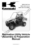
BRUTE FORCE 750 4×4iEPS
BRUTE FORCE 750 4×4i
KVF750 4×4 EPS
KVF750 4×4
All Terrain Vehicle
Assembly & Preparation
Manual
Foreword
In order to ship Kawasaki vehicles as efficiently as possible, they are partially disassembled before crating. Since some of the most
commonly removed parts have a direct bearing on a vehicle’s reliability and safety, conscientious pre-sale assembly and preparation become extremely important. Good setup procedures can prevent needless warranty claims
and give customers a greater sense of confidence in Kawasaki and their Kawasaki Dealers.
This Assembly and Preparation Manual explains step by step procedures of the following
items for all Kawasaki BRUTE FORCE 750 4×4i
EPS, BRUTE FORCE 750 4×4i, KVF750 4×4
EPS, KVF750 4×4.
WARNING
WARNING indicates a hazardous situation which, if not avoided, could result
in death or serious injury.
CAUTION
CAUTION indicates a hazardous situation which, if not avoided, could result
in minor or moderate injury.
NOTICE
NOTICE is used to address practices not
related to personal injury.
NOTE
1. Uncrating
2. Assembly
3. Preparation
○This note symbol indicates points of particular
The selling dealer assumes sole responsibility for any unauthorized modifications prior to
sale. Refer to your Service Binder for any Service Bulletins specifying Factory Directed Modifications (Special Claims) which must be performed before the vehicle is ready for sale.
Whenever you see the following symbols
heed their instructions! Always follow safe
operating and maintenance practices.
Kawasaki Heavy Industries, Ltd. accepts no
liability for any inaccuracies or omissions in this
publication, although every possible care has
been taken to make it as completely and accurately as possible. All procedures and specifications subject to change without prior notice.
interest for more efficient and convenient operation.
DANGER
DANGER indicates a hazardous situation which, if not avoided, will result in
death or serious injury.
© 2011 Kawasaki Heavy Industries, Ltd
Jan., 2011
Table of Contents
Uncrating ......................................................................................
Opening Crate (US and Canadian Models only) .........................
Opening Crate (Other than US and Canadian Models)...............
Parts Check .................................................................................
Assembly ......................................................................................
Handlebar....................................................................................
Hangtag.......................................................................................
French Labels..............................................................................
Owner’s Manual ..........................................................................
Preparation ...................................................................................
Battery Service ............................................................................
Air Cleaner ..................................................................................
Front Final Gear Case Oil ...........................................................
Rear Final Gear Case Oil ............................................................
Front Brake..................................................................................
Rear Brake ..................................................................................
Suspension..................................................................................
Tire Air Pressures........................................................................
Fuel .............................................................................................
Coolant ........................................................................................
Engine Oil....................................................................................
Throttle Lever and Cable .............................................................
Variable Differential Control Lever and Cable ............................
Rear Brake Light Switch Adjustment ...........................................
Headlight Beam ...........................................................................
Front Wheel Alignment ................................................................
Multifunction Meter ......................................................................
Fastener Check ...........................................................................
Standard Torque Table ................................................................
Test Ride .....................................................................................
A&P Check List ...........................................................................
3
3
6
7
10
10
11
11
12
13
13
16
17
18
19
20
21
22
22
22
23
24
25
26
26
26
29
32
34
34
34
UNCRATING 3
Uncrating
Opening Crate
(US and Canadian Models only)
Returnable Steel Crate (RSC):
NOTICE
To avoid damaging the front plastic
guard, fold down the front end of
the steel crate before removing the
tie-downs.
WARNING
Crates have sharp edges and may have
nails or screws that can cause cuts and
injury. Always wear protective gloves,
boots and eye protection when uncrating to prevent injury.
A. Outer Cover
• Remove the inner cover.
WARNING
The steel crate panel plates and fasteners have sharp edges. Always wear protective gloves, boots and eye protection
when uncrating to prevent injury.
A. Inner Cover
To work efficiently, start work at the rear of the
crate.
Remove the hairpin clips (2), then push out
the clevis pins (2) to disconnect the rear diagonal braces (2) from the rear upright.
•
a space about 6 m (20 ft) square to give
• Clear
yourself plenty of space to work.
the crate upright on its base.
• Place
Remove
the outer cover and inspect the unit
• for concealed
damage. If concealed damage
•
is evident, document the damage as outlined
in the Kawasaki Warranty Policies and Procedures Manual before proceeding to uncrate
the unit.
Remove the cardboard cover.
4 UNCRATING
A. Rear Upright
B. Hairpin Clip
C. Diagonal Brace
the diagonal braces to pivot out and
• Allow
down to the ground. They remain attached
•
to the pallet.
Install the hairpin clips (2) back into the braces
for return shipment to KMM.
A. Front Upright
B. Hairpin Clip
C. Diagonal Brace
NOTE
○Note that the front upright is collapsible (The
rear upright is not collapsible.).
it up while removing the second pin. Af• Hold
ter pin removal, allow the upright to collapse.
A. Hairpin Clip
B. Clevis Pin
C. Diagonal Brace
A. Front Upright
B. Diagonal Brace
the LH side rear diagonal brace,
• Remove
again allowing it to pivot down. At this time,
down the front upright. To do so, lift up on
• Lay
the front upright (lower section) to disengage
•
the rear upright may be pivoted down, but it
may not be necessary to do so. Only one
upright must be pivoted down before rolling
off the vehicle. In this example, the vehicle
will be rolled out the front, which is shown
later.
Moving to the front, disconnect the front diagonal braces (2) from the front upright. Pull out
the hairpin clips (2), push out the clevis pins
(2), and allow each diagonal brace to pivot
down to the ground. Install all pins and hairpin
clips back into the braces for return shipment
to KMM.
its sockets from the pallet.
A. Front Upright
B. Lower Section
UNCRATING 5
down the sides, remove the
• Working
tie-downs (2) which secure the vehicle to
the crate pallet.
A. Tie-down
the upright may be pivoted down to the
• Now
ground. (It remains attached to the pallet.) Be
•
careful not to drop it on anyone.
Roll off the vehicle.
RETURN SHIPMENT (RSC)
up slightly on the rear upright to disen• Pick
gage its sockets. Pivot it down onto the crate
pallet. Be careful not to drop on anyone.
A. Rear Upright
B. Socket
these steps for the other upright. (The
• Repeat
front upright is shown in this example.)
A. Front Upright
B. Diagonal Brace
the crate for return shipment. In this
• Prepare
example, we will begin at the rear of the crate.
around the diagonal braces so that
• Swing
they will lay on the crate pallet.
A. Front Upright
B. Diagonal Brace
A. Rear Upright
B. Diagonal Brace
clevis pins (4) and hairpin clips (4) are
• The
already installed into the braces. Notice that
it is necessary to collapse one upright so that
enough space exists for both uprights when
laid down.
6 UNCRATING
a space about 6 m (20 ft) square to give
• Clear
yourself plenty of space to work.
the crate upright on its base.
• Place
the outer cover and inspect the unit
• Remove
for concealed damage. If concealed damage
is evident, document the damage as outlined
in the Kawasaki Warranty Policies and Procedures Manual before proceeding to uncrate
the unit.
Remove the cardboard cover.
A. Rear Upright
B. Clevis Pins and Hairpin Clips
C. Front Upright
items are discarded:
• These
-Outer Cover, Inner Cover, Tie-downs (Qty.2)
the empty RSC may be stacked maxi• Now
mum 12 high for return shipment. Each empty
•
Removing Panels
a BPS3 square drive bit (ex. IM• Using
PORT APEX Square Recess “Power Bits1/4 Hex-size #3” or MAGNA “Insert Bits-size
#3” with quick change holder), remove the
screws from the sides and ends.
RSC weighs about 97 kg. (215 lbs.) so a
stack of 12 is very heavy. The empty crates
interlock at each corner for stability. No stacking bands are needed.
Opening Crate (Other than US and
Canadian Models)
WARNING
Crates have sharp edges and may have
nails or screws that can cause cuts and
injury. Always wear protective gloves,
boots and eye protection when uncrating to prevent injury.
A. “Power Bit (APEX)”
WARNING
Staples, nails and other fasteners have
sharp points that can cause injury. Remove or bend into the wood all staples,
nails or other fasteners in the crate base.
Disposable Wooden Crate:
out all the fasteners and remove the top
• Take
and sides of the crate.
UNCRATING 7
the top and side panels of the wood
• Remove
crate.
• Remove the inner cover.
NOTICE
Be careful not to puncture a tire with
sharp fasteners when rolling off the vehicle from the crate base.
the tie-downs (2) which secure the
• Remove
vehicle to the crate pallet and roll off the vehicle.
A. Tie-downs
Parts Check
the parts including Owner’s Manual
• Remove
from the parts bag on the footboard.
the battery electrolyte from the rear
• Remove
end of the chassis.
A. Electrolyte
8 UNCRATING
the parts against the illustrations. There may be minor differences between these
• Check
illustrations and the actual vehicle parts.
UNCRATING 9
No.
Part Name
1 French Label and Instruction for
KVF750GCF Canadian Model only
Instruction, Label
Label, Vehicle Emission Information
KVF750HCF Canadian Model only
Instruction, Label
Label, Vehicle Emission Information
KVF750JCF Canadian Model only
Instruction, Label
Label, Vehicle Emission Information
KVF750LCF Canadian Model only
Instruction, Label
Label, Vehicle Emission Information
2 French Labels for Canadian Model only
Label, Age
Label, General
Label, Passenger
Label, Tire Pressure
Label, Trailer Towing
Label, Shifting
Label, Transmission
Label, Protective Cover
Label with Band, General for English
Label with Band, General for French
Label, Air Cleaner Information
Cover, Label
3 French Labels and Instruction for European Model
Instruction, Label
Label, Protective Cover
Label, Shifting
Label, Transmission
Label, Passenger
Label, Air Cleaner Information
4 For US Model only
Label with Band, General
Label with Band, Exhaust Emission Air Index
5 Ignition Key
6 Battery Electrolyte, KMX14-BS
7 Owner’s Manual
Qty
Remarks
1
1
56030-0403
59465-0046
1
1
56030-0730
59465-0627
1
1
56030-0731
59465-0629
1
1
56030-0717
59465-0604
1
1
1
1
1
1
1
1
1
1
1
1
56040-1325
56071-0059
56071-0097
56071-0074
56071-0080
56071-0092
56070-0039
56070-1271
56030-0194
56030-0197
56033-0308
14092-0127
1
1
1
1
1
1
56030-0337
56070-1271
56071-0092
56070-0039
56071-0097
56033-0308
1
1
2
1
1
56030-0194
49007-0706
–
12 V 12 Ah
–
10 ASSEMBLY
Assembly
Handlebar
Handlebar Installation
the screws (D = 5, L = 16) (4) to
• Remove
remove the front handlebar cover.
A. Handlebar Clamp Bolts
B. Handlebar
C. Punched Mark
D. Clamp
Handlebar Clamp Bolt Tightening
A. Screws
B. Front Handlebar Cover
the screws (D = 5, L = 14) (3) to
• Remove
remove the rear handlebar cover.
the front clamp bolts first, and then
• Tighten
the rear clamp bolts to the specified torque. If
the handlebar clamps are correctly installed,
there will be no gap at the front and a gap at
the rear after tightening.
Handlebar Clamp Bolt Torque:
29 N·m (3.0 kgf·m, 22 ft·lb)
A. Rear Handlebar Cover
B. Screws
C. Well Nuts
NOTE
○Be careful not to drop the well nuts when you
removing the rear handle cover.
the handlebar clamp bolts and lift the
• Loosen
handlebar up.
the handlebar to match its punched mark
• Set
to the upper edge of the gap between the
handlebar clamp.
A.
B.
C.
D.
○It
Front Clamp Bolts
Rear Clamp Bolts
No Gap
Gap
NOTE
is recommended that the front handlebar
cover should be installed after completing the
steps in the “Throttle Lever and Cable” and
“Differential Control Lever and Cable” sections in the PREPARATION chapter.
○It is recommended that the rear handlebar
cover should be installed after completing the
step in the “Throttle Lever Free Play Adjustment” in the PREPARATION chapter.
ASSEMBLY 11
Hangtag
French Labels
Exhaust Emission Air Index Hangtag Installation (For US Model)
For Canadian Model:
is an exhaust emission air index hang• There
tag included into the removed parts. Hang it
NOTE
○Stick the French labels onto the English labels
on the front fender, rear fender, or the seat
only when required.
to the left handlebar as shown.
off any oil or grease from the English
• Wipe
labels. Refer to the following photographs in
•
the label locations.
Peel each French label off the backing sheet
and apply it over the English label.
A. Exhaust Emission Air Index Hangtag
(49007-0706)
B. Left Grip
NOTE
○This hangtag is not to be removed before sale.
General Hangtag Installation (For US
and Canadian Models)
is a general hangtag included into the
• There
removed parts. Hang it to the right handlebar
as shown.
A. General Hangtag
(56030-0194, US and Canada English
Models)
(56030-0197, Canada French Model)
B. Right Grip
NOTE
○This hangtag is not to be removed before sale.
1. Air Cleaner Information (56033-0308)
2. Age Recommendation Warning (56040
-1325)
3. General Warning (56071-0059)
4. Shifting Caution (56070-0092)
5. Protective Cover Warning (56070-1271)
12 ASSEMBLY
For European Model:
6. Passenger Warning (56071-0097)
7. Tire Pressure & Maximum Loading Warning
(56071-0074)
8. Transmission Warning (56070-0039)
*9. Vehicle Emission Control Information
French Label for KVF750GCF Canadian
Model only (59465-0046)
French Label for KVF750HCF Canadian
Model only (59465-0627)
French Label for KVF750JCF Canadian
Model only (59465-0629)
French Label for KVF750LCF Canadian
Model only (59465-0604)
Stick the label cover (14092-0127) onto the
vehicle emission control information label
(59465-xxxx).
*: Attached in the back of the seat.
1. Important Air Cleaner Information (56033
-0308)
2. Shifting Caution (56071-0092)
3. Protective Cover Warning (56070-1271)
•
4. Transmission Warning (56070-0039)
5. Passenger Warning (56071-0097)
Owner’s Manual
storage box is located on the left side
• The
front fender. Keep this Owner’s Manual and
•
10. Trailer Towing Warning (56071-0080)
other light items in this storage box.
Keep the cover securely fastened with the
strap when driving the vehicle.
PREPARATION 13
A.
B.
C.
D.
Owner’s Manual
Cover
Strap
Storage Box
Preparation
Battery Service
Battery Removal
The battery used in this vehicle is a sealed
type and never needs to be refilled. Follow the
procedures for activating a new battery to ensure the best possible battery performance.
A. Bolt with Collar
B. Screws with Collars
C. Battery Cover
Battery Activation
Electrolyte Filling
sure that the model name of the elec• Make
trolyte container matches the model name of
the battery. These names must be the same.
Battery Model Name
KVF750G/H/J/L: KMX14-BS
Seat Removal
the seat by pulling up the seat latch
• Remove
lever located at the left rear end of the seat,
and then pull the seat up and to the rear.
A. Model Name of the Electrolyte
B. Model Name of the Battery
NOTICE
A. Seat Latch Lever
the battery holder bolt (D = 6, L = 16)
• Remove
with collar (D = 6.3) to and screws (D = 6, L
•
= 18) (2) with collars (D = 6.3) (2) remove the
battery cover.
Take the battery out of the battery case.
Be careful that any rubber dampers are not
pulled out of position.
Be sure to use the electrolyte container
with the same model name as the battery
since the electrolyte volume and specific gravity vary with the battery type.
This is to prevent overfilling of the electrolyte, shorting the battery life, and deterioration of the battery performance.
NOTICE
Do not remove the aluminum sealing
sheet from the filler ports until just prior
to use. Be sure to use the dedicated
electrolyte container for correct electrolyte volume.
14 PREPARATION
WARNING
The electrolyte contains sulfuric acid,
which can cause severe burns.
To
avoid sulfuric acid burns, wear protective clothing and safety glasses when
handling electrolyte. If the electrolyte
touches the skin or eyes, wash the area
with liberal amounts of water and seek
medical attention for more severe burns.
the battery on a level surface.
• Place
Check
see that the sealing sheet has no
• peeling,totears,
or holes in it.
Remove
the
sealing
sheet.
•
NOTE
○The battery is vacuum sealed.
If the sealing
sheet has leaked air into the battery, it may
require a longer initial charge.
A. Strip of Caps
B. Sealed Cells
the electrolyte container upside down
• Place
with the six sealed cells into the filler ports
of the battery. Hold the container level, push
down to break the seals of all six cells. You
will see air bubbles rising into each cell as the
ports fill.
NOTE
○Do not tilt the electrolyte container.
A. Sealing Sheet
B. Filler Ports
the electrolyte container from the
• Remove
vinyl bag.
the strip of caps from the container
• Detach
and set aside, these will be used later to seal
the battery.
NOTE
○Do not pierce or otherwise open the sealed
cells of the electrolyte container. Do not attempt to separate individual cells.
the electrolyte flow.
• Check
If
no
air
are coming up from the filler
• ports, orbubbles
if the container cells have not emptied completely, tap the container a few times.
NOTE
○Be careful not to have the battery fall down.
PREPARATION 15
A. Air Bubbles
B. Tap the Container
the container in place. Don’t remove
• Keep
the container from the battery, the battery re-
NOTICE
Once the strip of caps is installed onto
the battery, never remove the caps, nor
add water or electrolyte to the battery.
quires all the electrolyte from the container for
proper operation.
NOTICE
Removal of the container before it is
completely empty can shorten the service life of the battery.
filling, let the battery sit for 20 ∼ 60
• After
minutes with the electrolyte container kept in
•
•
place, which is required for the electrolyte to
fully permeate into the plates.
Make sure that the container cells have emptied completely, and remove the container
from the battery.
Place the strip of caps loosely over the filler
ports, press down firmly with both hands to
seat the strip of caps into the battery (don’t
pound or hammer). When properly installed,
the strip of caps will be level with the top of
the battery.
NOTE
○Charging the battery immediately after filling
can shorten service life.
Initial Charge
activated sealed batteries require an
• Newly
initial charge.
Standard Charge:
1.2 A × 5 ∼ 10 hours
a recommended battery charger, fol• Iflowusing
the charger’s instructions for newly activated sealed battery.
Kawasaki-recommended chargers:
Battery Mate 150-9
OptiMate PRO 4-S/PRO S/PRO 2
Yuasa MB-2040/2060
Christie C10122S
the above chargers are not available, use
• Ifequivalent
one.
Let
battery
30 minutes after initial charge,
• then check sitvoltage
using a voltmeter. (Voltage immediately after charging becomes temporarily high. For accurate measuring, let the
battery sit for given time.)
A. Strip of Caps
16 PREPARATION
○Charging
NOTE
rates will vary depending on how
long the battery has been stored, temperature, and the type of charger used. If voltage
is not at least 12.8 volts, repeat charging cycle.
○To ensure maximum battery life and customer
satisfaction, it is recommended the battery be
load tested at three times its amp-hour rating
for 15 seconds.
Re-check voltage and if less than 12.8 volts
repeat the charging cycle and load test. If still
below 12.8 volts the battery is defective.
Air Cleaner
Air Cleaner Element Inspection
The foam air cleaner element on ATV models
is oiled prior to shipping. However, over time
the filter will dry and filtration performance will
diminish.
Pull release the snaps and remove the air
cleaner housing cap and inspect the foam air
cleaner element for proper oiling.
•
Battery Installation
the ignition switch to OFF.
• Turn
Check
the rubber dampers on the battery
• holder that
and the battery case are properly in
•
•
•
•
place.
Put the battery in place.
Securely connect the red cable with protective cap and the black cable with the round
terminal and the red tape to the (+) terminal,
and then securely connect the black cable to
the (–) terminal.
On the battery (+) terminal, make sure the
round terminal cable is on the red cable making about 30 degree angle with the red cable.
Put a light coat of grease on the terminals to
prevent corrosion.
Cover the (+) terminal with its protective cap.
A. Battery
B. Positive Terminal (+)
C. Negative Terminal (–)
D. Red Tape
E. About 30°
the battery cover, bolt, screws (2)
• Reinstall
and collars (3) in the reverse order of removal.
A. Air Cleaner Housing Cap
B. Snaps
the air cleaner element is dry, remove the
• Ifscrew
(D = 6, L = 5) and washer and pull out
the air cleaner element and the element frame
from the air cleaner housing.
A.
B.
C.
D.
Air Cleaner Element
Air Cleaner Housing
Screw and Washer
Element Frame
the air filter element from the ele• Remove
ment frame.
PREPARATION 17
A. Air Cleaner Element
B. Element Frame
the air cleaner element with a
• Saturate
high-quality foam air filter oil (ex. Kawachem
•
•
“Foam Filter Oil”, Bel Ray “Foam Filter Oil”,
Maxima “FFT Foam Filter Treatment”, or
equivalent cohesive type) and make sure
that the oil is evenly applied throughout the
air cleaner element. Squeeze out the excess
oil, but do not wring the air cleaner element
as this could cause tearing. In this case, too
much oil is better than too little. Finally pat
the inside of the air cleaner element with a
paper towel to remove any excess oil.
Install the air cleaner element to the element
frame.
Insert and tighten the screw to the specified
torque.
A. Front Hooks
B. Front Receivers
C. Rear Hooks
D. Rear Receivers
E. Latches
F. Latch Lever
up the rear end of the seat to make sure
• Pull
it is securely locked.
Front Final Gear Case Oil
Front Final Gear Case Oil Level Inspection
the vehicle level front-to-rear and side-to
• With
-side, remove the filler cap from the front final
gear case.
Torque : 3.5 N·m (0.36 kgf·m, 31 in·lb)
• Reinstall the air cleaner housing cap.
Seat Installation
the front hooks with the front receivers
• Align
and slide the seat forward. Make sure that
the rear hooks align to their rear receivers.
Push the seat with both hands around the rear
hooks and make sure there is a click sound of
the latches engaging.
A. Front Final Gear Case
B. Filler Cap
C. Front Axle Shaft
NOTICE
Be careful not to allow any dirt or foreign materials to enter the front final
gear case.
the oil level. The oil level should come
• Check
to the bottom thread of the filler opening. If
it is insufficient, add oil through the oil filler
opening as necessary.
18 PREPARATION
A. Front Final Gear Case
B. Filler Opening
C. Bottom Thread
Front Final Gear Case Oil
(Equivalent to engine oil)
Type:
A. Rear Final Gear Case
B. Filler Cap
NOTICE
Be careful not to allow any dirt or foreign materials to enter the rear final gear
case.
API SG, SH, SJ, SL or SM with
JASO MA, MA1 or MA2
Viscosity: SAE 10W-40
Capacity: 0.40 L (0.42 US qt)
the oil level. The oil level should come
• Check
to the bottom thread of the filler opening. If
Although 10W-40 engine oil is the recommended oil for most conditions, the oil viscosity
may need to be changed to accommodate
atmospheric conditions in your riding area.
NOTE
it is insufficient, add oil through the oil filler
opening as necessary.
○Front and rear final gear cases use different
types of oils. Use the specified type and brand
of oil in each final gear case.
Rear Final Gear Case Oil
Type:
Mobil Fluid 424,
CITGO TRANSGARD
TRACTOR HYDRAULIC FLUID
or
EXXON HYDRAUL 560
Capacity: 0.72 L (0.76 US qt)
• Install the filler cap.
Oil Filler Cap Torque:
29 N·m (3.0 kgf·m, 22 ft·lb)
Rear Final Gear Case Oil
Rear Final Gear Case Oil Level Inspection
the vehicle level front-to-rear and side-to
• With
-side, remove the filler cap from the rear final
gear case.
NOTE
○Do not apply front final gear case oil into the
rear final gear case. Apply only the specified
oil. The rear final gear case contains brake
plates which require a special oil type. Also
the two different oil types for the rear gear
case oil must not be mixed in use.
PREPARATION 19
A. Rear Final Gear Case
B. Filler Opening
C. Bottom Thread
• Install the filler cap.
Oil Filler Cap Torque:
29 N·m (3.0 kgf·m, 22 ft·lb)
Front Brake
Front Brake Fluid Level Inspection
the front brake reservoir horizontal,
• Position
and check that the fluid level in the reservoir
is higher than the lower level line.
A. Lower Level Line
fluid level in the reservoir is lower than
• Ifthethelower
level line, check for fluid leaks in the
•
•
front brake lines and fill the reservoir.
Loosen the screws to remove the front brake
fluid reservoir cap and diaphragm.
Fill the reservoir to the upper level line with
DOT4 brake fluid. Inside the front brake
reservoir is a stepped line showing the upper
level line.
A. Upper Level Line
WARNING
When working with the disc brake, observe the precautions listed below.
1. Never reuse old brake fluid.
2. Do not use fluid from a container that has
been left unsealed or that has been open
for a long time.
3. Do not mix two types and brands of fluid
for use in the brake. This lowers the
brake fluid boiling point and could cause
the brake to be ineffective. It may also
cause the rubber brake parts to deteriorate.
4. Don’t leave the reservoir cap off for any
length of time to avoid moisture contamination of the fluid.
5. Don’t change the fluid in the rain or when
a strong wind is blowing.
6. Brake fluid quickly ruins painted surfaces; any spilled fluid should be completely wiped up immediately.
7. If any of the brake line fittings or the
bleed valve is opened at any time,
the AIR MUST BE BLED FROM THE
BRAKE LINE.
the front brake lever several times.
• Operate
it feels spongy, there might be air in the
• Ifbrake
line.
If
necessary,
bleed the air in the rear brake
• line.
check for fluid leakage around the fit• Also
tings, and bleed the air in the front brake lines.
Brake Line Air Bleeding
the front brake reservoir horizontal, re• With
move the front brake reservoir cap and diaphragm, and check that there is plenty of
fluid in the reservoir.
20 PREPARATION
NOTE
○The fluid level must be checked several times
during the bleeding operation and replenished
as necessary. If the fluid in the reservoir runs
completely out any time during bleeding, the
bleeding operation must be done over again
from the beginning since air will have entered
the line.
a clear plastic hose to the bleed valve
• Attach
on the caliper and run the other end of the
•
•
hose into a container.
With the reservoir cap off, slowly pump the
brake lever several times until no air bubbles
can be seen rising up through the fluid from
the holes at the bottom of the reservoir. This
bleeds the air from the front brake master
cylinder end of the line.
Pump the brake lever a few times until it
becomes hard and then, holding the lever
squeezed, quickly open (turn counterclockwise) and close the bleed valve. Then release
the lever. Repeat this operation until no more
air can be seen coming out into the plastic
hose.
the previous step one more time for
• Repeat
the other front disc brake.
air bleeding is finished, check that the
• When
fluid is between the upper and lower level
•
•
lines.
Install the diaphragm and the reservoir cap.
Tighten the bleed valve(s) to the specified
torque.
Torque : 7.8 N·m (0.8 kgf·m, 69 in·lb)
the brake lever forcefully for a few sec• Apply
onds, and check for fluid leakage around the
fittings.
Rear Brake
Brake Pedal Position Inspection
the adjusting bolt length.
• Measure
be 5 mm (0.20 in.).
It should
A. Adjusting Bolt
B. Locknut
C. 5 mm (0.20 in.)
Brake Pedal Position Adjustment
A. Hold the brake lever applied.
B. Release the brake lever.
adjust the pedal position, loosen the lock• To
nut, turn the adjusting bolt and make the bolt
length 5 mm (0.20 in.), and then tighten the
locknut. Now adjust the brake pedal free play.
Brake Pedal Free Play Inspection
the parking brake.
• Release
Measure
distance the brake pedal moves
• before thethebrake
starts to take hold. Pedal
free play should be 15 ∼ 25 mm (0.6 ∼ 1.0 in.).
Brake Pedal Free Play:
15 ∼ 25 mm (0.6 ∼ 1.0 in.)
A. Quickly open and close the bleed valve.
PREPARATION 21
A. Brake Pedal
B. 15 ∼ 25 mm (0.6 ∼ 1.0 in.)
Brake Pedal Free Play Adjustment
adjust the pedal free play, turn the brake
• To
pedal adjuster at the rear end of the brake
cable.
A. 1 ∼ 2 mm (0.04 ∼ 0.08 in.)
B. Locknut
C. Adjuster
○Since
NOTE
the above two free play adjustments
(pedal and lever) affect each other, make
them at the same time.
adjustments, check for brake drag (there
• After
should be none) and effectiveness.
Suspension
Front and Rear Shock Absorber Spring
Preload Adjustment
the position of the spring
• Check
adjusting sleeves (Turn here with
A. Brake Lever Adjuster
B. Brake Pedal Adjuster
C. Rear Wheel (Left Side)
Rear Brake (Parking) Lever Free Play
Inspection
preload
a hook
wrench) on the front and rear shock absorbers.
STD Position:
Front: No. 2
Rear: No. 2
the rear brake lever free play. If the
• Check
free play is incorrect, adjust the free play.
Rear Brake Lever Free Play:
1 ∼ 2 mm (0.04 ∼ 0.08 in.)
Rear Brake (Parking) Lever Free Play
Adjustment
the rubber cover.
• Slide
Loosen
locknut and turn the adjuster at
• the brakethelever
in as far as it will go.
Tighten
the
locknut.
• Turn the adjuster at the rear end of the brake
• cable so that the brake lever has 1 ∼ 2 mm
(0.04 ∼ 0.08 in.) of free play.
A. Rear Shock Absorber
B. Spring Adjusting Sleeve
22 PREPARATION
the adjusting sleeve on the shock ab• Turn
sorbers to the standard position with a hook
•
wrench.
Check to see that each pairs of adjusting
sleeves are turned to the same relative position.
WARNING
If a pair of adjusting sleeves are not
adjusted equally, handling may be impaired and a hazardous condition may
result. Adjust the sleeves equally.
Tire Air Pressures
Tire Air Pressure Adjustment
the pressures to the specified values
• Adjust
in the front and rear, and make sure to tighten
the caps securely.
Tire Air Pressures (when cold):
[Normal Use]
Front: 35 kPa (0.35 kgf/cm², 5 psi)
Rear: 35 kPa (0.35 kgf/cm², 5 psi)
Fuel
WARNING
Gasoline is extremely flammable and
can be explosive under certain conditions, creating the potential for serious
burns. When filling the tank, turn the
ignition switch to “OFF”. Do not smoke.
Make sure the area is well-ventilated and
free from any source of flame or sparks;
this includes any appliance with a pilot
light.
the fuel tank with one gallon/or four liters of
• Fill
unleaded gasoline. Use gasoline with a minimum octane rating indicated in the following
table.
The antiknock index is an average of the Research Octane Number (RON) and the Motor
Octane Number (MON), as shown in the table.
For US and Canadian Models
Octane Rating Method
Antiknock
Index
(RON + MON)
2
Minimum
Rating
87
For Other than US and Canadian Models
Octane Rating Method
Research Octane Number (RON)
Minimum
Rating
91
the fuel tank cap and check for any
• Close
leaks and correct them.
A. Air Pressure Gauge
○To
NOTE
accurately measure the pressure, use a
low air pressure gauge included in the tool kit
of ATV. Do not use an automotive air pressure
gauge because the specified tire air pressures
of ATV is too low.
Coolant
Coolant Reservoir Tank Level Check
the vehicle on level ground.
• Situate
Check
the
level through the coolant
• level gaugecoolant
on the reserve tank. The coolant
level should be between the “F” (Full) and “L”
(Low) marks.
NOTE
○Check the level when the engine is cold (room
or atmospheric temperature).
PREPARATION 23
A. Reserve Tank
B. “F” (Full) Mark
C. “L” (Low) Mark
D. Cap
E. Front Shock Absorber (Right Side)
the amount of coolant is insufficient, un• Ifscrew
the cap from the reserve tank and add
A. Oil Drain Plug
the vehicle so that it is level, both side-to
• Park
-side and front-to-rear.
starting the engine, check that the en• Before
gine has oil.
the oil filler plug on the lower left side
• Unscrew
of the engine and wipe the dipstick dry. Then
screw it in again. Unscrew the plug and check
that the engine has oil.
coolant through the filler opening to the “F”
(Full) mark. Install the cap.
Recommended Coolant Solution
Coolant Mixture Ratio:
Water 50%: Coolant 50% (1:1)
Recommended Coolant:
Permanent type coolant (ethylene
glycol plus corrosion and rust inhibitor
chemicals for aluminum engines and
radiator).
NOTE
○A permanent type of antifreeze is installed in
the cooling system when shipped. It is colored green and contains ethylene glycol. It is
mixed at 50% and has the freezing point of
–35°C (–31°F).
A. Oil Filler Plug
replacing the plug, be sure the O-ring
• When
is in place, and screw the plug in finger tight.
NOTICE
If the engine is run without oil, it will be
severely damaged.
Engine Oil
Engine Oil Level Inspection
NOTE
○This vehicle’s engine is filled with 10W-30 oil
from the factory. DO NOT DRAIN and refill
the crankcase before use. Check oil level and
drain plug tightness.
Engine Oil Drain Plug Torque:
20 N·m (2.0 kgf·m, 15 ft·lb)
the engine and run it for several minutes
• Start
at idle speed. Stop the engine, then wait sev-
•
•
eral minutes until the oil settles.
Unscrew the oil filler plug, wipe its dipstick dry,
and screw it in again.
Unscrew the plug and check the oil level. The
oil level should be between the H (High) and
L (Low) lines on the dipstick.
24 PREPARATION
Throttle Lever and Cable
Throttle Lever Free Play Inspection
the throttle lever free play. If the free
• Check
play is incorrect, adjust the throttle cable.
Throttle Lever Free Play:
2 ∼ 3 mm (0.08 ∼ 0.12 in.)
that the throttle lever moves smoothly
• Check
from full open to close, and the throttle closes
quickly and completely in all steering positions by the return spring. If the throttle lever
does not return properly, check the throttle
lever free play, cable routing, and for possible cable damage. Then lubricate the throttle
cable.
A. Oil Filler Plug and Dipstick
B. Screw in the oil filler plug fully to
inspect the oil level
C. “H” (High) Line
D. “L” (Low) Line
oil level is too high, remove the excess
• Ifoilthe
through the oil filler opening using a syringe
•
•
or some other suitable device.
If the oil level is too low, add the oil to reach
the correct level.
Screw the plug in finger tight.
Recommended Engine Oil
Type:
API SG, SH, SJ, SL or SM with
JASO MA, MA1 or MA2
Viscosity: SAE 10W-40
Capacity: 1.9 L (2.0 US qt)
[when filter is not removed]
2.0 L (2.1 US qt)
[when filter is removed]
A. 2 ∼ 3 mm (0.08 ∼ 0.12 in.)
the engine at the idle speed, and turn the
• Run
handlebar all the way to the right and left to
ensure that the idle speed does not change.
If the idle speed increases, check the throttle
lever free play and the cable routing.
Although 10W-40 engine oil is the recommended oil for most conditions, the oil viscosity
may need to be changed to accommodate
atmospheric conditions in your riding area.
WARNING
Operation with incorrectly routed or improperly adjusted cables could result in
an unsafe riding condition. Be sure the
cables are routed correctly and properly
adjusted.
Throttle Lever Free Play Adjustment
the rubber cover off of the adjuster at the
• Slide
throttle case.
the locknut and turn the throttle ca• Loosen
ble upper adjuster to obtain the specified free
•
play.
Tighten the locknut and reinstall the rubber
cover.
PREPARATION 25
A. Adjuster
B. Locknut
the rear handlebar cover with the
• Reinstall
screws (D = 5, L = 14) (3), and tighten them.
A. Variable Differential Control Lever
B. Handlebar Grip
C. 20 mm (0.8 in.)
Variable Differential Control Lever Position Adjustment
the screws (D = 5, L = 16) (4) to re• Loosen
move bolt front handle cover.
A. Rear Handlebar Cover
B. Screws
C. Well Nuts
Variable Differential Control Lever
and Cable
By pulling the control lever toward the handlebar, the driving force of the front wheels can be
equalized to provide more traction. If the differential control lever has excessive play, adjust
the differential control cable.
Variable Differential Control Lever Position Inspection
the variable differential control lever to• Pull
wards the handlebar grip with a spring scale
until it reads 30 N (3 kgf, 7 lb) of force. The
clearance between the control lever and grip
should be 20 mm (0.8 in.). If the clearance is
not within specification, adjust the cable.
Variable Differential Control Lever Position:
20 mm (0.8 in.) from the grip
A. Screws (D = 5, L = 16)
B. Front Handle Cover
the locknut at the middle of differential
• Loosen
control cable.
the adjuster until the cable has the
• Turn
proper amount of play.
• Tighten the locknut after adjustment.
26 PREPARATION
A. Variable Differential Control Cable
B. Locknut
C. Adjuster
the front handlebar cover with the
• Reinstall
screws (D = 5, L = 16) (4), and tighten them.
Rear
Brake
Adjustment
Light
Switch
Rear Brake Light Switch Adjustment
the ignition switch to "ON" position.
• Turn
Depress
pedal. The brake light
• should gotheon brake
after about 10 mm (0.4 in.) of
A.
B.
C.
D.
Brake Light Switch
Adjusting Nut
Lights later
Lights sooner
Headlight Beam
headlight beams can be adjusted verti• The
cally.
the adjusting screw on each headlight
• Turn
rim in or out to adjust the headlight vertically.
pedal travel.
A. Adjusting Screw
B. Headlight Body
A. Brake Pedal
B. 10 mm (0.4 in.)
adjust the brake light switch (located near
• To
the brake pedal), move the switch forward or
rearward by turning the adjusting nut.
NOTICE
To avoid damaging the electrical connections inside the switch, be sure that
the switch body does not turn during adjustment.
Front Wheel Alignment
Toe-in is the amount that the front wheels are
closer together in front than at the rear at the
axle height. When there is toe-in, the distance
A (Rear) is greater than B (Front) as shown.
If toe-in is incorrect, the front wheels will be
dragged along the ground, scuffing and wearing
the tread knobs. Caster and camber are built-in
and require no adjustment.
A (Rear) – B (Front) = Amount of Toe-in (Distance A and B are measured at axle height with
the vehicle sitting on the ground, or at 1G.)
PREPARATION 27
Steering Centering Inspection
•
Test ride the vehicle. If the handlebar is
straight when the vehicle is traveling in a
straight line, go on to the Toe-in Inspection
procedure. Otherwise, go on to the Steering
Centering Adjustment procedure.
A. Locknut (Left-hand Threads)
B. Locknut (Wheel Side)
C. Tie-rod
NOTICE
Adjust the tie-rod so that the visible
thread length is even on both ends of
the tie-rod, or the threads could be damaged.
Steering Centering Adjustment
a straightedge against the rear wheel rim
• Hold
on one side at axle height.
A. Straightedge
the handlebar straight ahead, loosen
• With
the locknuts [A] [B] and turn the tie-rod until
the front wheel on that side is parallel to the
straightedge.
○The
NOTE
locknut [A] on the tie-rod has left-hand
threads. Turn the wrench clockwise for loosening.
A. Visible Thread Length
the straightedge procedure on the
• Repeat
other side of the vehicle. Now the front
•
wheels are parallel to each other and to the
center line of the vehicle.
Go on to the Toe-in Inspection procedure.
28 PREPARATION
the measurement of the front from
• Subtract
the measurement of the rear to get the toe-in.
If the toe-in is not in the specified range, go
on to the Toe-in Adjustment procedure.
Toe-in of Front Wheels
Standard: –5 ∼ 15 mm (–0.20 ∼ 0.59 in.)
at 1G
Toe-in Adjustment
the locknuts [A] [B] and turn the tie
• Loosen
-rod the same number of turns on both sides
A. Front Wheels
B. Vehicle Center Line
C. Parallel each other.
D. Straightedges
E. Rear Wheels
to achieve the specified toe-in.
○The
NOTE
locknut [A] on the tie-rod has left-hand
threads. Turn the locknut clockwise for loosening.
Toe-in Inspection
a heavy coat of chalk or a paint line near
• Apply
the center of the front tires.
a needle nose scriber, make a thin
• Using
mark near the center of the chalk coating
while turning the wheel.
A. Locknut (Left-hand Threads)
B. Locknut (Wheel Side)
C. Tie-rod
NOTE
•
•
○The toe-in will be near the specified value, if
With the front wheels on the ground, set the
handlebar straight ahead.
At the level of the axle height, measure the
distance between the scribed or painted lines
for both front and rear of the front tires.
the tie-rod length [A] is 388.5 mm (15.30 in.)
on each tie-rod.
NOTICE
Adjust the tie-rod length so that the visible thread length is even on both ends of
the tie-rod. Uneven thread length could
cause tie-rod damage.
PREPARATION 29
A. Visible Thread Length
A. ODO Display
the toe-in.
• Check
Tighten
• torque. the tie-rod locknuts to the specified
ODO is not displayed, switch the me• Ifterthedisplay
mode by pushing the left button
Torque : 36 N·m (3.7 kgf·m, 27 ft·lb)
• Test ride the vehicle.
several times to shift the display mode to the
ODO.
Multifunction Meter
Check the km/h·mph Display in the Multifunction Meter
The km/h·mph display can alternate between
metric and English modes (km/h and mph) in
the meter unit. Make sure that km/h or mph
is correctly displayed according to local regulations before riding. If the measurement unit
displayed in the multifunction meter is not correct, switch it to the correct unit as follows.
A. ODO Display
B. TRIP A Display
C. TRIP B Display
D. HR Display
E. Push Left Button.
A. km/h·mph Display
the ignition key to “ON”.
• Turn
Check
to see if the ODO is displayed in the
• multifunction
meter.
NOTE
○The km/h or mph display can be switched over
only when the meter is in the ODO display
mode.
A. Left Button
B. Right Button
30 PREPARATION
km/h·mph display is shifted by pushing
• The
the Right button for less than two seconds
•
while pushing in the Left button during the
odometer is displayed.
Turn the ignition key to “OFF”.
PREPARATION 31
This page intentionally left blank.
32 PREPARATION
Fastener Check
torque values listed are for assembly and
• The
preparation items only, see the appropriate
Service Manual for a more comprehensive
list. Check tightness of all fasteners that are
in the table before retail delivery. Also check
to see that each cotter pin or circlip is in place.
PREPARATION 33
No.
Fastener
Frame/Steering
1 Tie-rod locknuts (Left and Right)
Brake
2 Front master cylinder clamp bolts
3 Front brake bleed valves (Left and Right)
4 Front brake caliper mounting bolts (Left and Right)
Wheel
5 Front and rear wheel nuts (First Torque)
Front and rear wheel nuts (Final Torque)
Suspension
6 Front and rear shock absorber mounting nuts (Left
and Right)
7 Front upper suspension arm pivot nuts (Left and
Right)
8 Front lower suspension arm pivot nuts (Left and
Right)
9 Rear upper and lower suspension arm pivot nuts
(Left and Right)
Engine
10 Engine oil drain plug
11 Front final gear case oil drain plug
12 Front final gear case oil filler cap
13 Rear final gear case oil drain plug
14 Rear final gear case oil filler cap
Cotter pin or Circlip
15 Tie-rod end nut cotter pins (Left and Right)
Steering knuckle joint nut cotter pins (Left and
16
Right)
17 Rear brake cable cotter pin
N·m
Torque
kgf·m
ft·lb
Remarks
36
3.7
27
8.8
7.8
25
0.90
0.80
2.5
78 in·lb
69 in·lb
18
S1
15
76
1.5
7.8
11
56
S2
S2
34
3.5
25
59
6.0
44
47
4.8
35
47
4.8
35
20
15
29
15
29
2.0
1.5
3.0
1.5
3.0
15
11
22
11
22
–
–
–
–
–
–
–
–
–
S1: Tighten the upper clamp bolt first, and then the lower clamp bolt.
S2: Tighten the nuts in a criss-cross pattern to the first and final specified torques.
34 PREPARATION
Standard Torque Table
This table relating tightening torque to thread
diameter, lists the basic torque for bolts and
nuts. Use this table for only the bolts and nuts
which do not require a specific torque value.
All of the values are for use with dry solvent
-cleaned threads.
General Fasteners:
Threads
Torque
dia. mm
N·m
kgf·m
ft·lb
5
3.4~4.9 0.35~0.50 30~43 in·lb
6
5.9~7.8 0.60~0.80 52~69 in·lb
8
14~19
1.4~1.9
10.0~13.5
10
25~34
2.6~3.5
19.0~25
12
44~61
4.5~6.2
33~45
14
73~98
7.4~10.0
54~72
16
115~155 11.5~16.0
83~115
18
165~225 17.0~23.0 125~165
20
225~325
23~33
165~240
Multifunction Meter:
Speedometer - check operation.
Fuel Level Gauge - check operation.
Clock - check operation.
Odo/Trip/Hour Meters - check operation.
Electrical System:
Headlight - check operation.
Taillight - check operation.
Brake Light - check operation.
Instrument Lights and Indicator Lights check operation.
European and UK Models only:
Reverse Light - check operation.
Other than US and Canadian Models:
Horn - check operation.
Engine Stop Switch Works:
No Unusual Noises:
No Fuel, Oil, Brake Fluid, or Coolant
Leaks:
PREPARATION COMPLETE.
Test Ride
• Complete the test ride checklist.
The control cables must
work without binding in
any steering position.
Steering:
Action is free from
lock-to-lock.
Suspension:
Check operation front and
rear.
Engine:
Electric starter works
properly and engine
starts promptly. Good
throttle response and
return.
Belt Drive Torque Smooth operation.
Converter:
Differential:
Smooth operation.
Forward-Reverse Smooth operation.
Shift:
Hi-Low Shift:
Smooth operation.
2WD-4WD Shift: Smooth operation.
Brakes:
Adequate, smooth
stopping power. Do
not drag.
Control Cables:
A&P Check List
• Complete the A&P Check List.
MODEL APPLICATION
Year
Model
2012
KVF750GCF
2012
2012
KVF750HCF
KVF750JCF
2012
KVF750LCF
Name
BRUTE FORCE 750 4×4i EPS
KVF750 4×4 EPS
BRUTE FORCE 750 4×4i EPS
BRUTE FORCE 750 4×4i EPS
BRUTE FORCE 750 4×4i
KVF750 4×4
Part No. 99931-1524-02