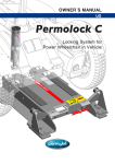
Download Permolock C3
Transcript
OWNER’S MANUAL
US
Permolock C3
Docking system for Power wheelchair in vehicle
How to contact Permobil
Head Office of the Permobil group
Permolock C3
Docking system for electric wheelchair in vehicle
Produced and published by Permobil AB, Sweden
Version no.: 7. 2014-03
Art. no.: 205237-US-0
Permolock C3 Owner´s Manual
Contents
Contents
Important information about the user manual.......................................................... 6
Safety instructions....................................................................................................... 8
General.................................................................................................................... 8
Warning labels......................................................................................................... 8
Design and function................................................................................................... 10
Operation..................................................................................................................... 11
General.................................................................................................................. 11
Docking the wheelchair......................................................................................... 13
Releasing the wheelchair...................................................................................... 14
Manual release of wheelchair................................................................................ 15
Emergency release of wheelchair......................................................................... 16
Overview, control button........................................................................................ 17
Accessories................................................................................................................ 20
Maintenance................................................................................................................ 22
Technical specifications............................................................................................ 22
Assembly.................................................................................................................... 23
Fitting of docking system in the vehicle................................................................ 24
Fitting of floor spacers .......................................................................................... 29
Fitting of manual release lever in a vehicle........................................................... 30
Identification of prepared wheelchair chassis (C300, K300, C350)...................... 32
Fitting of reinforcement plates on the wheelchair chassis (C350)........................ 32
Fitting of pins on the wheelchair chassis (C300, K300, C350)............................. 33
Fitting of pins on the wheelchair chassis (K450)................................................... 34
Fitting of pins on the wheelchair chassis (X850)................................................... 35
Fitting the transport lock for X850 in the vehicle................................................... 36
Troubleshooting guide.............................................................................................. 39
Sled test report........................................................................................................ 40-52
5
Permolock C3 Owner´s Manual
Important information
Important information about the user manual
Congratulations on choosing Permolock C3. Our aim is for you to feel satisfied
with your choice of supplier and product.
Before you start using your Permolock C3, it is important to read and understand
this user manual and in particular the section on safety.
The user manual is primarily designed to inform you about the Permolock C3,
its functions and capabilities, and to advise you on the best way of using it. It
also contains important safety information and describes some of the problems
which might arise in use.
Always keep the user manual in your vehicle, as you may need to consult its
important information on use, safety and maintenance.
You can also find information on our products on our website. You will find us
at www.permobil.com.
All the information and the pictures, illustrations and specifications are based
upon the product information that was available at the point in time this user
manual was printed.
Pictures and illustrations that appear in the user manual are typical examples
and are not intended to be exact depictions of different parts of the product.
We reserve the right to make changes to the product without prior notification.
6
Permolock C3 Owner´s Manual
Important information
TECHNICAL SUPPORT
In the event of technical problems, you should contact your dealer or Permobil
Inc USA at 1-800-736-0925.
Always state the chassis serial number when contacting Permobil to ensure
that the correct information is provided.
SPARE PARTS & ACCESSORIES
Spare parts and accessories must be ordered through your dealer.
WARRANTY & SERVICE
Permolock C3 is supplied with a 12-month warranty.
Service can be carried out in our own workshops or at authorized workshops.
You should only carry out servicing and maintenance designated by the user
manual as suitable for being carried out by the user. All other servicing and
maintenance must be carried out by persons with sufficient knowledge to give
a competent result.
Contact Permobil Inc for further information.
PRODUCT APPROVAL
This product fulfills the requirements of ISO 10542-1 and ISO 10542-3
7
Permolock C3 Owner´s Manual
Safety instructions
Safety instructions - General
Permolock C3 is a docking system for fixing Permobil electric wheelchairs in
place and is designed for use in vehicles.
It is important to read and follow the instructions and safety guidelines given in
this user manual before starting to use your Permolock C3, as mistakes in use
could lead to risk of injury to the user or passengers, or damage to the wheelchair, the Permolock C3 or the vehicle.
Any unauthorized alterations to Permolock C3 could lead to increased risk of
accident. Follow closely the recommendations in the section on Operation, in
order to avoid risk of accident during use.
Warning labels
You will see the following “warning labels” in the user manual. They are intended
to draw attention to situations which could lead to problems, near-accidents,
personal injury or damage to the wheelchair, etc.
m
CAUTION!
Take care here.
m
WARNING!
Take extra care here.
Risk of personal injury or damage to the wheelchair and its surroundings.
m
CAUTION!
Permobil INC accepts no liability for personal injury or damage to property which may arise from the failure of the user or other persons to follow
the recommendations, warnings and instructions given in this user manual.
8
Permolock C3 Owner´s Manual
Safety instructions
Safety instructions
m
WARNING!
To be checked before first use
Before using your wheelchair with Permolock C3, you must check that the chair
has been suitably adjusted. Contact your supplier for information.
To be checked before setting off
Check that the light on the control button in the vehicle is green after locking
has been activated.
Fitting
Permolock C3 should be fitted by a competent service engineer or a person
with adequate knowledge to perform the adjustment in an expert manner.
Maintenance and service
Carry out only the service and maintenance activities indicated in this user
manual. All other servicing, alterations and changes to the vital systems of
Permolock C3 and its accessories must be carried out by a competent service
engineer or a person with adequate knowledge to perform the adjustment in an
expert manner. In case of doubt, always contact a competent service engineer
or Permobil.
Use only spare parts or accessories approved or recommended by Permobil.
All other use could lead to changes which might impair the function and safety
of the docking system. It could also lead to the warranty for your Permolock
C3 becoming invalid.
m
WARNING!
Recycling of electronic items
Obsolete electronics should be disposed of responsibly in accordance with
local recycling regulations.
EMC requirements
The electronics in the vehicle locking system may be affected by external electromagnetic fields. Likewise the electronics in the locking system themselves
may emit electromagnetic fields which could affect the surrounding area.
The threshold values for Electro-Magnetic Compatibility (EMC) relating to electric wheelchairs and their accessories are laid down in harmonized standards
under EC Directive 93/42/EEC Medical Devices.
Permolock C3 meets these threshold values.
9
Permolock C3 Owner´s Manual
Design and function
Design & function
Permolock C3 is designed for use together with Permobil’s electric wheelchairs
approved for this purpose. Permolock C3 consists of two interacting units: Two
pins are fitted to the underside of the wheelchair chassis, along with a locking
plate fitted to the vehicle. During use, the locking plate’s locking mechanisms
mechanically hook around the pins on the wheelchair, locking it securely in place.
If the chassis in its original form does not have the pins, they must be fitted. The
chassis may also need to be supplemented with reinforcement plates so that the
wheelchair can be used together with the lock. (See the section Fitting.)
Permolock C3 is designed so that the user can either drive or reverse into the
lock if they are using a suitably adapted wheelchair. If the user is to sit in the
wheelchair during transport, the lock must be fitted in or against the direction of
movement in the driver or passenger space.
Permolock C3 can also be used as a transport lock, i.e. to transport the wheelchair without the user. When Permolock C3 is used as a transport lock, the user
should park the wheelchair and lock it securely using the C3. The user then
transfers to the driver’s ordinary driver or passenger seat. In such cases, the
lock can also be fitted laterally in the vehicle.
1
4
5
2
3
1. Pin
2. Control button
3. Release lever
4. Locking mechanism
5. Locking plate
10
Permolock C3 Owner´s Manual
Operation
Operation
General
Permolock C3 is designed to ensure that, in the event of a collision or other sudden movements of the vehicle, the wheelchair does not break free and cause
personal injury or material damage.
Permolock C3 must only be used together with Permobil electric wheelchairs
approved for this purpose and with the chair base available as an accessory.
It may be necessary to have your wheelchair adjusted to work with Permolock
C3. A test docking must always be performed in the presence of the person fitting the docking system.
11
Permolock C3 Owner´s Manual
Operation
Operation
General
Permolock C3 consists of two interacting units: Two pins are fitted to the
underside of the wheelchair chassis,
along with a locking plate fitted to the
vehicle.
A control button is fitted in the vehicle.
This button is available in two designs,
standard and advanced. The location of
the control button can vary, depending
on the vehicle and the user’s needs.
The picture shows an example of the
usual location of a standard button.
The control button gives various sound
and light signals depending on the status of the docking system. (See pages
17-19).
Example of position of control button
in the vehicle.
Control button, advanced design.
The docking system can be controlled
in three ways:
-
via the control button located inside
the vehicle (1).
-
via a manual release lever fitted
inside the vehicle next to the seat
(2).
-
via a manual emergency control on
the front of the lock (3).
1
2
Controlling Permolock C3.
12
3
Permolock C3 Owner´s Manual
Operation
Operation
Docking the wheelchair
The wheelchair is locked in place by moving the chair in towards the locking
mechanisms, which then hook securely to the two pins.
m
WARNING!
Be careful of the feet when moving the wheelchair into the docking system. Risk of personal injury.
Check that the light on the control button is green after docking has been activated.
If the user is to sit in the wheelchair during transport, always secure the feet fully to the foot plates
before commencing your journey. This reduces the risk of personal injury in the event of a collision.
If the ignition is turned on before the wheelchair is locked in position using
Permolock C3, the lock plate’s control button will shine orange and a five-second
sound signal will be emitted. This is a safety function to remind the user that the
wheelchair must always be locked in position before the vehicle is started.
1. Run the wheelchair straight over the docking system so that the two pins on
the wheelchair engage in the locking mechanism and mechanical stop. If this
takes longer than 15 seconds, the control button will indicate that there is a
problem. The system will then need to be reset, see pages 18-19.
2. Turn on the vehicle’s ignition. The control button shines green, which indicates that the wheelchair is correctly secured in position.
Run the wheelchair in over Permolock C3.
13
Permolock C3 Owner´s Manual
Operation
Operation
Releasing the wheelchair
The wheelchair is released electronically and activated using the control
button.
1. In order to open the locking mechanism of the docking system, press
the control button until it changes to
red. This indicates that the locking
mechanism has been opened and
that the wheelchair can be moved
out of the docking system.
If the vehicle’s ignition is still
switched on, a WARNING! signal
will also be emitted.
Example of position of control button
in the vehicle.
2. When the wheelchair is moved out
of the docking system, the control
button’s light will continue to shine
red.
After 15 seconds, the docking system will return to its original position
and is then ready for relocking. If
the vehicle’s ignition is still switched
on, the light on the control button
will change to orange.
Moving the wheelchair out of
Permolock C3.
14
Permolock C3 Owner´s Manual
Operation
Operation
Manual release of wheelchair
If the vehicle battery is flat, it will still be
possible to release the wheelchair manually. This is done using the release
lever available as an accessory to the
docking system. The location of the
manual release control in the vehicle
varies, depending on the type of vehicle
and the user’s requirements.
m
CAUTION!
In the event of manual release on a steep
upwards gradient, the wheelchair may simultaneously be carefully “driven” into the docking
system to facilitate release.
1. To open the locking mechanism
manually, move the lever to its open
position (see picture).
Lever for manual release.
The locking mechanism is opened
so that the wheelchair can be
moved out of the docking system.
m
CAUTION!
Always reset the locking mechanism to the
locked position after moving the wheelchair out
of the docking system.
2. When the wheelchair is moved out
of the docking system, the locking
mechanism is reset to the locked
position by moving the release control to the locked position.
The docking system is then ready to
be used again.
15
Moving the wheelchair out of
Permolock C3.
Permolock C3 Owner´s Manual
Operation
Operation
Emergency release of the
wheelchair
In an emergency, the locking mechanism can be opened manually using the
emergency handle on the front edge of
the locking plate.
m
CAUTION!
The user will need assistance in operating the
manual emergency locking control.
1. Pull the control for emergency
unlocking directly forward forcefully
(see picture) until the locking mechanism opens and the wheelchair is
released.
2. Hold the control in the extended
position while the wheelchair is
moved out of the docking system.
16
The control for emergency unlocking
is pulled directly forward.
Permolock C3 Owner´s Manual
Operation
Operation
Overview, control button
The following pages explain the different indications the control button may display when using Permolock C3. There are also suggestions for possible causes
and action. (see the section Troubleshooting as well.)
Before docking
INDICATION
POSSIBLE CAUSE
ACTION
The ignition is not
switched on.
No action.
The light is orange
The ignition is on, but
there is no wheelchair
in the docking system.
The docking system is
ready for use. This indication is a safety function to remind the user
that the wheelchair
must always be locked
in position before the
vehicle is started.
No action. The docking
system is ready for use.
The light is shining
orange and a fivesecond long sound
signal is heard.
The ignition is being
switched on, but there
is no wheelchair in
the docking system.
The docking system is
ready for use. This indication is a safety function to remind the user
that the wheelchair
must always be locked
in position before the
vehicle is started.
No action. The docking
system is ready for use.
No indication
17
If required, the wheelchair
is released as normal by
pressing the control button.
Permolock C3 Owner´s Manual
Operation
Operation
When docking
INDICATION
POSSIBLE CAUSE
ACTION
The light is shining
green
The ignition is on.
The wheelchair is correctly secured. Once
the ignition has been
turned off, the light will
shine green for a further 15 seconds.
No action.
The light flashes red
and a five-second long
audio signal is heard.
The ignition is on.
The wheelchair is not
docked correctly.
Reset the system by
pressing the control button for ten seconds.
Move the wheelchair out
of the docking system
and try again.
18
Permolock C3 Owner´s Manual
Operation
Operation
When docking
INDICATION
The light is shining
red
POSSIBLE CAUSE
The ignition is not on.
The locking mechanism is closing.
The manual release
lever is not in the
locked position.
The light is shining red
and a five-second long
audio signal is heard.
The lock has opened
while the ignition is
on. This indication is
a safety function to
remind the user that
the wheelchair must
always be locked during transport.
19
ACTION
If the light does not change
to green, reset the system
by pressing the control
button for ten seconds.
Move the wheelchair out
of the docking system and
try again.
Make sure the release
lever is in the locked position and that the wheelchair is fully in or out of
the docking system.
Reset the system by
pressing the control button for ten seconds.
Move the wheelchair out
of the docking system
and try again.
Permolock C3 Owner´s Manual
Accessories
Accessories
Chair base
Permits use of original car seat in Permolock C3.
Art. no: 1824275
Adjustable Chair base
Permits use of original car seat in Permolock C3.
Art. no: 1821551
Manual release handle
Makes it possible to release the wheelchair manually
if, for instance, the vehicle’s electrical system does not
function as it should.
Art. no: 102841-99-0
Quick release for Manual handle
Used for rapid and simple fitting/removal of the release
lever.
Art. no: 102859-99-0
Control button, advanced design.
Art. no: 1824735
Extension cable
Used, when required, to extend the cabling for
Permolock C3.
Art. no: 1823604
20
Permolock C3 Owner´s Manual
Accessories
Accessories
Reinforcement plates C350
Art. no: 104637-99-0
Locking pins C300, K300, C350
Art.no.: 104626-99-0
Locking pins K450
Art.no.: 1824325
Locking pins incl. reinforcement
plates X850
Art.no.: 1825146
Adapter plate X850
Art.nr: 1825280
Floor spacers
When fitting Permolock C3 to a slanted surface, it may
be necessary to use spacers on the vehicle floor in
order to make it easer to move the wheelchair in and
out.
Art. no: 104707-99-0
21
Permolock C3 Owner´s Manual
Design and function
Maintenance
Cleaning
The following is general advice recommended by Permobil. For severe soiling or
damage to surface finish, contact Permobil for information.
For normal cleaning proceed carefully with a soft cloth/sponge, hot water and a
mild detergent.
m
WARNING!
Never hose the docking mechanism down as the electronics may be damaged.
Technical specifications
DATA
General
Name................................................................................
Dimensions and weight
Length..............................................................................
Width................................................................................
Height...............................................................................
Permolock C3
12”
11”
3”-4”
Weight.............................................................................. 22 Pounds.
Electrical system
Voltage ............................................................................ 12V
22
( 310 mm.)
(280 mm)
(72-97 mm.)
(10 Kg)
FITTING
Permolock C3
Docking system for electric wheelchair in vehicle
Permolock C3 Owner´s Manual
Fitting
Fitting
Fitting a docking system to the vehicle - General
m
CAUTION!
To ensure that the wheelchair pins end in the correct position for locking, it is important that the
locking plate is mounted correctly in relation to the wheelchair chassis. The height of the locking
plate can therefore be adjusted to six different height positions. The docking system is sprung to
make moving in and locking on a sloping surface easier (see example below). The docking system
should not be fitted on a sloping surface if the wheelchair is to be backed in.
In some cases, it may be necessary to fit spacers to the vehicle floor in order to be able to lock
the wheelchair securely, see 27.
The docking system must be anchored in a manner that is safe for the type of vehicle involved and
which conforms to the relevant country’s regulations.
The docking system must be anchored in such a way that other components are not damaged and
the strength of the vehicle floor is not impaired.
Fitting on a sloping surface
m
CAUTION!
Check after installation that the docking system is not warped and that the docking system functions correctly.
The docking system must be tested with the user sitting in the wheelchair.
Check that the wheelchair shock absorbers are set for the right user weight – see the chassis
service manual. Permobil recommends that solid tires are used for the wheelchair.
24
Permolock C3 Owner´s Manual
Fitting
Fitting
Fitting Permolock C3
Read through the instructions before starting fitting.
1. Position the docking system in the right position in the vehicle.
2. Fit the docking system in the car using a screw, minimum quality M10 8.8,
through the vehicle floor. The screw must go right through and have the
required reinforcement washer and nut on the underside. At the rear of the
docking system, fit the attached reinforcement plate on the inside of the
docking system. See page 27.
m
CAUTION!
Screws are not supplied with Permolock C3. The recommended quality of the screws is M10 8.8,
with length adapted according to the floor thickness of the vehicle.
3. Connect the locking plate’s cabling to the vehicle’s electrical system.
Connect the red cable to the fused +12V (10A).
Red cable
-
12V (10A)
Black cable
-
Earth
Orange cable -
Ignition
Height adjustment of locking plate
The height of the locking plate can be adjusted to six different positions by fixing the central element to different holes in the bottom section of the docking
system. The lowest part has two holes on one side (high – low) and three holes
on the other side (1, 2 and 3).
If Permolock C3 is fitted to a level surface, it can be fixed in a level position with
screws that go through the lock’s middle and top sections. The hole to be used
for locking varies for the different positions - see pages 25-27.
3
2
1
High
Low
Holes in the lowest part of the docking system.
25
Permolock C3 Owner´s Manual
Fitting
Fitting
Height adjustment of locking
plate (cont.)
Position 1
(low – 1): Height 72 mm. If the wheelchair needs to be backed in, this position must be locked securely in a level
position.
Position 2
(low – 2): Height 76.5 mm. If the wheelchair needs to be backed in, this position must be locked securely in a level
position.
Position 3
(low – 3): Height 81.5 mm. Standard
fitting for Permobil C300 on a level
surface. If the wheelchair needs to be
backed in, this position must be locked
securely in a level position.
1
Low
Locking
Position 1.
2
Low
Locking
Position 2.
3
Low
Locking
Position 3.
Position 4
(high – 1): Height 87 mm. Standard
fitting for Permobil C350/M300/M400 on
a level surface. If the wheelchair needs
to be backed in, this position must be
locked securely in a level position.
1
High
Locking
Position 4.
Position 5
(high – 2): Height 92 mm. Only used for
fitting on a sloping surface. This position cannot be locked securely and may
not be used if the wheelchair is to be
backed into the docking system.
26
2
High
Position 5.
Permolock C3 Owner´s Manual
Fitting
Fitting
Position 6
(high – 3): Height 97 mm. Only used for
fitting on a sloping surface. This position cannot be locked securely and may
not be used if the wheelchair is to be
backed into the docking system.
Fine tuning of the height at assembly of the docking system
The height of the docking system can
be fine tuned by fitting desired quantity
of the attached spacers (B). See fig. to
the right.
At the rear of the docking system, fit the
attached reinforcement plate (A) on the
inside of the docking system. See fig.
to the right.
Fit the docking system parallell to the
bottom of the wheelchairs chassis and
with clearence just enough to make the
chassis and the docking system not
touch each other when the user is seated in the wheelchair. See fig. below.
3
High
Position 6.
A
B
Fine tune the height with suitable
number of spacers (B).
Fit the attached reinforcement plate
(A) at the rear.
Fit the docking system parallell to the bottom of the wheelchairs chassis and
with clearence just enough to make the chassis and the docking system not
touch each other when the user is seated in the wheelchair.
27
Permolock C3 Owner´s Manual
Fitting
Setting adjustment screws
If the docking system is fitted to a sloping surface, the adjustment screws in
the front of the docking system must be
screwed to the highest possible position
when the chair is in the docking position. This is so the top section of the
docking system cannot spring forward.
1. Move the wheelchair into the docking system.
2. Note the position of the docking
system’s top section and move the
wheelchair out of the docking system.
3. Unscrew the screws so they are
level with the top section of the
docking system (see picture) when
the wheelchair is moved into the
docking system again.
4. Move the wheelchair into the docking system and check that the
screws are at the right level.
28
Adjustment of screws.
Permolock C3 Owner´s Manual
Fitting
Fitting floor spacers
When fitting the lock on a sloping
surface, it may be necessary to use
spacers under the wheelchair’s wheels
in order to make it easer to move the
wheelchair in and out.
1. Secure the spacers to the vehicle
floor using a screw of a suitable
length depending on the thickness
of the floor.
29
Permolock C3 with spacers.
Permolock C3 Owner´s Manual
Fitting
Fitting
Fitting of manual release lever in vehicle
Read through the instructions before starting fitting.
The manual release lever must be installed
so that the user can easily operate it when
necessary. The lever is intended for use
where the vehicle’s electrical system is
not functioning optimally.
Remove the plastic cover from the lever
by manually unclipping the sides of the
cover at the bottom edge, see picture.
Preliminary adjustment
The release mechanism can be turned
to suit installation on either the right or
left side.
m
The plastic cover can be
unclipped by hand.
WARNING!
The handle must always be fitted so that the
stop screw (2) is located in front of the release
lever (1), see page 31. This prevents the release
lever opening by itself in the event of a collision.
1
1. Move the stop screw between positions 2 and 7, see picture.
2. Remove the cable bracket (5) from
the release arm (10) (see picture).
3. Turn the release arm (10) and move it
between attachment points 4 and 9.
4. Refit the cable bracket (5) to the
release arm (10) (see picture).
Fitting
2
7
3
8
4
9
10
5
6
1. Install the release lever using three
M4 screws with countersunk heads
through holes 3, 6 and 8 (see picture).
2. Refit the plastic cover.
Manual release lever.
30
Permolock C3 Owner´s Manual
Fitting
Fitting
Correct fitting
O = Position of the stop screw
Prohibited fitting
Fitting the release lever
31
Permolock C3 Owner´s Manual
Fitting
Fitting
Identification of prepared
chassis
In order to be able to fit reinforcement
plates and pins in the wheelchair’s
chassis, the chassis must be prepared
for this. A prepared chassis has two
holes for the pins on the underside, see
picture.
Holes on the underside
of prepared chassis.
Fitting reinforcement plates
in the wheelchair’s chassis
(C350)
2
Read through the user manual before
commencing fitting.
1. Remove the wheelchair’s chassis
cover. For a detailed description,
see the chassis service manual.
1
2. Remove the two battery holders (1).
Cut away the bottom sections by
the narrowest part (2) if the battery
holders are of this type.
m
Removal and adjustment
of battery holder.
CAUTION!
It is not necessary to remove the battery when
fitting reinforcement plates, but it may make the
work easier.
3
3. Position the reinforcement plates (1
and 2) in the grooves on both sides
of the battery and push them firmly
against the shaft (see picture).
4. Secure the reinforcement plates
using the accompanying screws
and washers.
5. Refit the battery holders (3 and 4),
see picture.
32
1
4
2
Fastening reinforcement plates and
battery holder.
Permolock C3 Owner´s Manual
Fitting
Fitting
Fitting of pins in the wheelchair chassis
Read through the instructions before starting fitting.
1. Remove the wheelchair’s chassis cover. For a detailed description, see the
service manual for the chassis in question.
2. Lift/angle the wheelchair so that the underside of the chassis can be
accessed.
m
WARNING!
The wheelchair is heavy, so ensure it remains stable after the chassis has been lifted/angled.
3. Lift out the cabling and electronics that are in the way.
4
3
2
1
Fitting pins.
4. Push in the pin (1) and spring (2) from the underside of the chassis (see picture).
5. Press the pin in and check that it springs back.
6. Press in the pin against the chassis underside and screw the lock nut securely
(3) onto the pin’s thread. There is a recess in the pin for an allen key. Check that
the pin can be pressed in and that it returns to its outer position.
7. Press the cable protection (4) securely into the holes, if these are not
factory fitted.
8. Put the wheelchair down on all four wheels again.
9. Refit the wheelchair’s chassis cover.
33
Permolock C3 Owner´s Manual
Fitting
Fitting
(K450)
Fitting pins to the wheelchair
chassis
Read through these instructions before
you commence fitting.
1. Remove the wheelchair’s battery
covers. For a detailed description,
see the chassis service manual.
2. Use the battery belt to pull/lift the
batteries from the chassis.
Fitting a locking pin.
3. Apply Loctite 2701 to the threads of
the accompanying screws.
4. Fit the locking pins to the wheelchair
chassis. See picture. The screws
holding the locking pins should be
tightened from the underside of
the chassis using a torque wrench.
Hold on to the locking pins using
pliers.
Tightening torque: 45 Nm.
5. Replace the batteries and the plastic battery covers.
6. Fit the accompanying warning sticker to the control panel. See picture.
m
Fit the accompanying warning
sticker to the control panel.
WARNING!
If locking pins are mounted, chassis clearance
will be reduced to 40 mm.
34
Permolock C3 Owner´s Manual
Fitting
Fitting
(X850)
Fitting pins to the wheelchair
chassis
Read through these instructions before
you commence fitting.
1. Remove the wheelchair’s chassis
cover and batteries. For a detailed
description, see the chassis service
manual.
2. Lower the reinforcement plates into
the relevant battery compartment.
Note that there is a right and left
plate. Secure with a washer and
screw from the outside of the chassis. See picture.
3. Drip Loctite onto the screws to be
threaded into the pins under the
chair. The screws are fitted from the
battery compartment. Use a socket
head bit for M10 screws and tighten
from underneath the chassis using
a torque wrench. Hold onto the pins
from underneath the chassis using
pliers, etc.
Tightening torque: 65 Nm.
4. The accompanying warning sticker
should be applied to the control
panel. Figure 3.
Reinforcement plates with associated
screws and washers.
Drip Loctite onto the screws
and tighten with a torque
wrench to 65 Nm.
5. The accompanying warning sticker
should be applied to the control
panel. Figure 3.
m
WARNING!
This product is only for use as a transport lock.
Must NOT be used for personal transport.
Incorrect use can lead to a risk of injury to the
user or passenger, or damage to the wheelchair, Permolock C3 or vehicle.
Sticker to be stuck to control panel.
35
Permolock C3 Owner´s Manual
Fitting
Fitting
(X850)
Fitting a transport lock in the vehicle
Read through the instructions before you commence fitting.
m
WARNING!
This product is only for use as a transport lock. Must NOT be used for personal transport. Incorrect
use can lead to a risk of injury to the user or passenger, or damage to the wheelchair, Permolock
C3 or vehicle.
1. Place the plate as per picture 1, where the arrow symbolizes the direction of
travel of the vehicle.
2. The transport bracket must be fitted in the front set of holes if the user
intends to drive forwards into the bracket, pos 1. Use the rear set of holes if
the chair is to be reversed into the bracket, pos 2.
1
2
2
1
The fitting positions for the transport bracket.
36
Permolock C3 Owner´s Manual
Fitting
Fitting
(X850)
3. Secure the lock to the plate using
a screw, minimum quality M10 8.8
(the screws are NOT included in
the kit). The screw must go right
through and have the required reinforcement washer and nut. The
accompanying spacers must be
used between the bracket and the
floor plate.
Floor plate, spacers
and transport lock.
4. Replace the two screws that adjust
the height of the bracket using
the attached screws and washers.
See picture. Secure in the bracket’s
top positions. The bracket’s front
screws do not need to be replaced.
The screws should be tightened
with 47 Nm torque.
Tightening torque: 47 Nm.
Drip Loctite onto the screws
and tighten with a torque
wrench to 65 Nm.
Cont. on next page.
Secure the screws in the
bracket’s top positions.
37
Permolock C3 Owner´s Manual
Fitting
Fitting (X850)
5. Adjust the height of the bracket by pressing down on the spring-lock side
at the bottom. Turn the two adjustment screws until a height of 85 mm is
reached. See picture.
6. Connect the cabling for the vehicle’s electrical system. Connect the red
cable to the fused +12V (10A).
Red cable
-
12V (10A)
Black cable
-
Earth
Orange cable -
Ignition
PRESS
85 mm
Adjust the height to 85 mm.
38
Permolock C3 Owner´s Manual
Troubleshooting
Troubleshooting guide
The following troubleshooting guide describes a number of errors and events
which could occur when using your Permolock C3, together with suggested
remedies. Please note that this guide does not describe all the problems and
incidents that may arise. You should always contact your service contact or
Permobil in the event of uncertainty.
EVENT
POSSIBLE CAUSE
ACTION
The light on the locking
plate control button flashes
red.
Electronics fault
The light on the locking
plate control button shines
red during manual release.
The locking mechanism is
not in the locked position.
Make sure the locking mechanism is in locked position and
that the wheelchair is fully in or
out of the docking system.
The docking system does
not unlock when its control
button is pressed. (The
docking system can always
be unlocked using the manual release handle).
Electronics fault
Reset system by pressing the
control button for 10 seconds.
The light on the locking
plate control button flashes
irregularly.
The tension spring is broken.
Contact service
The locking mechanism’s
locking arm is loose.
Contact service
The manual release lever is
in open position.
Move the manual release lever
to the closed position.
The locking mechanism’s
adjustment device is broken.
Contact service
The spring pins have got
stuck in the chassis.
Contact service
The height has been
incorrectly adjusted on
Permolock C3.
Adjust the height of Permolock
C3, see pages 25-27.
The wheelchair is not
locked in position in
Permolock C3.
The wheelchair does not
fit into Permolock C3 when
driven in over the docking
system.
Reset system by pressing the
control button for 10 seconds.
Contact service
Contact service
39
Permolock C3 Owner´s Manual
Sled test report
40
Permolock C3 Owner´s Manual
Sled test report
41
Permolock C3 Owner´s Manual
Sled test report
42
Permolock C3 Owner´s Manual
Sled test report
43
Permolock C3 Owner´s Manual
Sled test report
44
Permolock C3 Owner´s Manual
Sled test report
45
Permolock C3 Owner´s Manual
Sled test report
46
Permolock C3 Owner´s Manual
Sled test report
47
Permolock C3 Owner´s Manual
Sled test report
48
Permolock C3 Owner´s Manual
Sled test report
49
Permolock C3 Owner´s Manual
Sled test report
50
Permolock C3 Owner´s Manual
Sled test report
51
Permolock C3 Owner´s Manual
Sled test report
52
US
Permolock C3
Art. no.: 205237-US-0


