1
Section 4 — Operation
The Model 296 basic Set Stop Valve is complete with all
accessories and controls necessary to provide automatic
two-stage shutdown for a typical loading operation when
used in conjunction with a two-stage set stop counter or
similar device.
The valve is designed to operate in conjunction with a
Model 15A Low Flow Start Timer, a Model 40 Rate of
Flow Control, a Model 50A Pressure Reducing Control, a
Model 60A Back Pressure Control, and others (consult
factory). It is recommended that at least one (1) modulating pilot (such as a rate of flow control) be used to keep
the valve in a modulating condition at all times. This
assures the necessary emergency shutdown response
time, thereby minimizing accidental overruns. This
manual’s principles of operation are based on the 296-40.
The Model 296 basic Set Stop Valve is designed to accomplish the following basic functions:
1. Adequately control the flow to affect an accurate
zero shutoff, without excessive line shock, by utilizing a two-stage shutdown.
2. Limit the flow rate to the meter’s maximum rating by
adding the rate of flow pilot (40A), thus avoiding
meter damage.
3. Limit the downstream pressure by adding the pressure reducing pilot (50A), thus protecting the truck
manifold (bottom loading).
4. Limit the overrun to a safe quantity, guarding against
spills if the emergency shutdown has to be actuated.
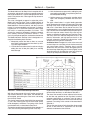
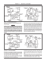
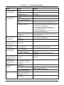
The graph, shown below, is a typical loading operation
curve representing the sequence of operation for the 296
Set Stop Valve. Each major control component on the
296 valve is listed down the left side of the chart. The
loading operation curve is divided into 8 zones from left to
right. This will allow a breakdown of the principle of operation into 8 separate zones. Note that the text and examples are based on including the Low Flow Start Timer.
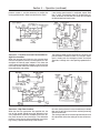
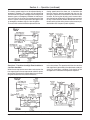
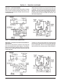
The heavy dark lines indicate energized circuits in the
electrical schematics and high-pressure circuits in the
hydraulic schematics. Dotted lines indicate inter- mediate pressure in the hydraulic schematics.
Installation Note: Entrapped air in the valve cover and/
or control loop can cause the valve to function erratically
and cause severe shocks. Therefore, the air must be
vented from the valve cover and/or the highest point in
the control loop. Open the gate valve only slightly so that
the entire meter run (including the motor and valve) can
slowly fill up with product while the air is vented.
Zone No. 1 - Valve Closed Start-Up Procedure
With the set stop counter in the “off” position and the set
stop counter switches A and B open, the solenoids are
de-energized, pressurizing the valve cover and holding
the valve fully closed.
The closing speed control should initially be opened one
(1) turn, thus assuring that the valve will close quickly
under emergency conditions. Fine-tuning of this control
must be done later, as described in Zone No. 5.
The opening speed control should initially be opened to 1/
2 turn, thus assuring slow opening of the valve, help-
ing to eliminate any severe surprises. Fine-tuning of this
control will be done later, as described in Zone No. 4.
The rate of flow control has been adjusted at the factory
for the flow rate specified on the log sheet, based on
customer specification or maximum rating of meter if
known. Therefore, adjustment at this time is not normally
required. Fine-tuning of this control will be described in
Zone No. 5.
The low flow start timer coil wire should be disconnected
so that all the Zone No. 3 adjustments can be made
without the interference from the timer.
Issue/Rev. 0.3 (1/03)
MN03005 • Page 5