1
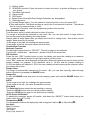
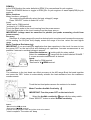
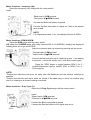
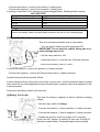
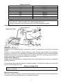
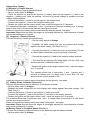
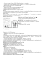
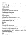
6300/6300A/6300B
3 3/4 DIGITAL AUTOMOTIVE ENGING
ANALYZER MULTIMETER
OPERATION
MANUAL
This instrument is a compact 、battery operated、handheld with safety protector 、
streamline 、 3 3/ 4 digital automotive engine analyzer multimeter for measuring DC/AC Voltage,
DC/ AC Current, Resistance, , Capacitance, Frequency and Duty cycle, Temperature,
Diode/Continuity test, Tachometer, Dwell .ms-PULSE,Analog
Frequency/Duty/Voltage/Resistance Signal Output ,It is an ideal instrument for all drivers.
Safety
DANGER
Engines produce carbon monoxide which is odorless, causes slower reaction time .and can lead
to serious injury .when the engine is operating keep service areas WELL VENTILATED or attach
the vehicle exhaust system to the shop exhaust removal system.
Set the parking brake and block the wheels before testing or repairing the vehicle .it is
especially important to block the wheels on front-wheel drive vehicles: The parking brake dose
not hold the drive wheels.
Wear an eye shield when testing or repairing vehicles .exceeding the limits of this meter is
dangerous, it will expose you to serious or possibly fatal injury .carefully read and understand the
cautions and the specification limits of this meter.
Voltage between any terminal and ground must not exceed 1000V DC or 750V AC.
Use caution when measuring voltage above 25VAC or DC.
Circuit tested must be protested by a 10A fuse or circuit breaker.
Do not use the meter if it has been damaged
Do not use the test leas if the insulation is damaged or metal is exposed .
Use current clamps to measure circuits exceeding 10A.
Danger
Avoid electrical shock : do not touch the test leads ,tips or the circuit being tested.
Do not try a voltage measurement with the test leads in the 10A or the mA terminal.
*When testing for the presence of voltage or current . make sure the meter is function
correctly ,take a reading of a known voltage or current before accepting a zero reading.
*Choose the proper range and function for the measurement . do not try voltage or current
measurements that may exceed the ratings marked on the function/range switch or terminal.
*When measuring current. Connect the meter in series with the load.
*Never connect more than one set of test leads to the meter.
*Disconnect the live test lead before disconnecting the common test lead.
*The mA and the 10A terminals are protected by fuses . to avoid possible injury or damage . use
only in ciruits limited to 400mA or 10A continuous for 15 seconds .
See also
Fuse Replacement
IMPORTANT
*To maintain accuracy of the meter , replace the discharged battery immediately when the
battery symbol
appears on the meter display .
*Avoid measuring error form outside interference : keep the meter away form spark plug or coll
wires .
*Avoid damaging the meter when testing voltage : disconnect the test leads form the test points
before changing functions.
*Do not exceed the limits shown in the table below:
Function
Terminal
Input Limit
AC Volts
750V AC rms
V/Ω/RPM
DC Volts
1000V DC
Frequency
V/Ω/RPM
250V AC/DC
1
Ohm (resistance)
Diode
AC/DC 400mA
AC/DC 10A
RPM
Duty Cycle(%)
Dwell angle
mA
10A
400mA AC/DC
*10A AC/DC
V/Ω/RPM
250V AC/DC
10Amp measurement continuous for 15 seconds maximum.
Ohm can not be measured if voltage is present ,ohms can be measured only in a non-powered
circuit .however ,the meter is protected to 250 volts.
SPECIFICATION
GENERAL SPECIFICATION
Display: 3-3/4 digits LCD with 25mm high numerals.
Auto Functions: Auto-zero, Auto-polarity, Auto-range
Auto power off: 30 minutes after stopping the switch or no push button, the meter enter to
Power off mode. Push button or run switch, Auto Power off disable.
Low Battery Indication: " ".
Overrange Indication: "OL".
Power Supply: single 9V battery (NEDA 1604or IEC 6F22)
Reading Rate Time: 3 reading per sec(approx.).
Maximum Commom Mode Voltage: 500Vdc or ac peak.
Safety Standards: The meter is up to the standards Of IEC1010 Double Insulation,
Pollution degree 2 Overvoltage Category Ⅱ.
Operating Environment: 0℃ to 50℃(32℉to 122℉) at ≤70% relative humidity.
Storage Envrionment: -20℃ to 60℃(-4℉ to 140℉) at ≤80% relative humidity .
Temperature Coefficient: 0.1×(specified accuracy)/℃(≤18℃ or≥28℃)
Accessories: One pair test leads, single 9V battery (NEDA 1604or IEC 6F22), operating
instructions.
Fuse: 0.5A/250V, 5×20mm fast acting,10A/250V, 5×20mm fast acting.
Dimension : 158mm×97mm×50mm
Weight :Approx. 320g(including battery and holster).
Electrical specifications
*Accuracy is given as ±([% of reading]+[ number of leads significant digits]) at 18℃ to 28℃(65
℉ to 83℉),with relative humidity up to 70%.
RPM(tach) (Only DT-6300/6300A)
Ranges:600-4000,4000-12000(×10RPM)
Resolution :1 RPM
Effect reading :>600RPM
Accuracy:±(2.5%rdg+10dgt)
Overload protection:250VDC or RMS AC
Pulse width (Only DT-6300/6300A)
Ranges :0.1ms-10.0ms
Accuracy :±(2.5%+0.2ms)
Overload protection:250VDC or RMS AC
% Duty cycle
ranges:0.0-90.0%
resolution:0.1%
pulse width :>100us,<100ms
Accuracy:±(2.5%rdg+10dgt)
Overload protection:250VDC or RMS AC
2
Dwell angle (Only DT-6300/6300A)
No.of cylinder:4.5.6.8
Range:0-90.0゜(4 cyl),0-72.0゜(5CYL),0-60.0゜(6CYL),0-45.0゜(8CYL.)
Resolution:0.1゜
Accuracy:±(2.5%rdg+10dgt)
Overload protection:250VDC or RMS AC
Temperature(Only DT-6300/6300A)
Ranges:-50 to 1100℃,-50 to 2000℉
Resolution:1℃/1℉
Accuracy:±(1%rdg+2℃)
±(1%rdg+4℉)
sensor: type K thermocouple
input protection:60VDC or 24VAC rms
DC voltage(auto rangeing)
Ranges:400mV
Accuracy:± (2.5%rdg+15dgt)
Ranges:4V,40V,400V,1000V
Accuracy:± (0.8%rdg+8dgt)
Resolution:100uV
input impedance:>10MΩ
Overload protection: 1000VDC or 750VAC rms.
AC VOLTAGE(Auto ranging)
Ranges:400mV,4V,40V,400V,750V,(400mV only in manual)
Resolution:100uV
Accuracy: : 400mV ,750V± (3.0%rdg+15dgt) at 50Hz to 100Hz
,4V,40V,400V, ± (1.5%rdg+15dgt) at 50Hz to 400Hz
input impedance:>10MΩ
Overload protection: 1000VDC or 750VAC rms.
DC CURRENT
Ranges: 40mA,400mA,10A.
Resolution:0.1uA
Accuracy: 40mA,400mA ±(1.5%rdg+10dgt)
10A ±(2.0%rdg+15dgt)
Input protection: 0.5A/250V fuse on 400mA range
10A/250V high energy fuse on 10A range
AC CURRENT
Ranges: 40mA,400mA,10A.
Resolution:0.1uA
Frequency response:50Hz to 400Hz
Accuracy: 40mA,400mA ±(1.8%rdg+15dgt)
10A ±(2.5%rdg+15dgt)
Input protection: 0.5A/250V fuse on 400mA range
10A/250V high energy fuse on 10A range
RESISTANCE(Auto ranging)
Ranges:400Ω,4KΩ,40KΩ,400KΩ,4MΩ,40MΩ
Accuracy:±(1.5%rdg+15dgts) on 400Ω range
±(1.0%rdg+10dgts) on 4kΩ to 4MΩ ranges
±(2.5%rdg+15dgts) on 40MΩ ranges
open circuit voltage: 0.4VDC
overload prctection: 250VDC or RMS AC.
FREQUENCY(Auto ranging)
Ranges:100Hz,1KHz,100KHz,200KHz
Resolution:0.01Hz
Accuracy: ±(0.1%rdg+5dgts)
3
Sensitivity:1V
Overload protection:250VDC or RMS AC
CAPACITANCE(Auto ranging)
Ranges:40nF,400nF,4uF,40uF,100uF.
Resolution:10pF
Accuracy:±(2.5%rdg+10dgts) on 40nF range
±(1.5%rdg+10dgts) on 400nF to 4uF ranges
±(2.5%rdg+15dgts) on 40uF to100uF ranges
overload protection:250VDC or RMS AC
DIODE TEST
Test current: 0.6mA typical
Resolution:1mV
Accuracy:±(2.5%rdg+2gdts)
Open circuit voltage: 3.0Vdc typical
Overload protection:250VDC or RMS AC.
AUDIBLE CONTINUITY
Open circuit voltage:0.4Vdc
≤60Ω Buzzer sounds
Overload protectio n:250VDC or RMS AC.
Signal analog Output(Analog Frequency/Duty/Voltage Signal Output)(Only DT-6300)
FREQUENCY:20Hz-3KHz
% Duty cycle:10%-90%
VOLTAGE:0-5V
Signal analog Output(Analog Frequency/Duty/DC and AC Voltage/RESISTANCE Signal
Output)(Only DT-6300B)
FREQUENCY:20Hz-3KHz
% Duty cycle:10%-90%
DC VOLTAGE:0-1V、0-5V、0-12V
AC VOLTAGE: 0-5V、0-12V
RESISTANCE: 0-5KΩ,0-200KΩ
9V BATTERY CHARGE(Only DT-6300A/6300B)
Accessory optional
1.
2.
3.
RPM INDUCTIVE PICK-UP PROBE
9V BATTERY CHARGEABLE
CHARGER
Getting Started
This chapter will help you get started.
It describes the basic functions of the meter.
Front Panel
4
1) Hz/Duty switch
2) RPM/DIS Hz switch: Press the button to select a function. A symbol will display to verify
your choice.
3) Hold/Back light switch
4) Range switch
5) REL switch
6) Square Wave Output(Hz/Duty/Voltage Parameter are changeable)
7) Safety protector
8) Function/Range switch: Turn this switch to select a function or turn the meter OFF.
9)Test lead terminal: The Black test lead is used in the Com terminal for all test . The red test
lead is used to measure Amps or Volts
temperature Terminal: insert the temperature probe in this terminal.
Function and e select
Turn the rotary switch in either direction to select a function.
The range is automatically selected by the meter. But ,you can also select a range within a
function by pressing by pressing the range button.
Always select a range higher than you expect the current or voltage to be . then select a lower
range if better accuracy is needed
*if the range is too high ,the reading are less accurate.
*if the range is too low ,the meter shows OL(over limit)
Push-button Functions
Alternate Function
The altemate function button is “SELECT”. Press it to toggle to the alternate
Function(AC, audible and capacitance ) shown in blue on the meter face.
REL function
Press the zero “REL” function button to zero the display and store the reading as a reference
value. press and hold the button for two(2)seconds to exit this mode.
In the “REL” mode the value displayed is always the difference between the stored value and the
present reading .for example .if the reference value is 24.00V and the present reading is
12.50V.the display will indicate-11.50V if the mew reading is the the same as the reference value .
the display will be zero.
Range select
The range is automatically selected by the meter . But ,you can also manually select arrange
within a function by pressing the RANGE button.
Range Exit
To exit the RANGE mode and return to auto ranging .press and hold the RANGE button for 2
seconds.
NOTE:
*If the range is too high .the readings are less aceurate.
*If the range is too low . the meter shows OL(over limit)
Date Hold
The Date Hold feature stores the last reading in memory
*Press the HOLD button once to hold the present reading.
*Press the HOLD button again to exit and resume readings.
AUTO Power Off Disable
To disable the automatic power off function ,hold down the “SELECT” button while turning the
meter switch form OFF to ON.
Temperature(℃/℉)
The temperature feature will display the data in degrees Celsius (℃) or Fahrenheit(℉)
See Also:
Meter Functions
*Duty Cycle
*ms Pulse
Duty Cycle ,what is it?
5
RPM/Dis
In the RPM function the meter defaults to RPM(1) for conventional 4-cycle engines.
Press the RPM/DIS button to toggle to RPM(1)for 2-cycle engines or waste spark(DIS)4-cycle
engines.
Meter functions
Meter functions -voltage(V)
The meter will automatically select the best voltage(V) range.
Press “SELECT” button to select AC or DC.
Insert:
*black lead in COM terminal.
*red lead in V/Ω/RPM terminal .
Touch the Black probe to the circuit coming from the power source.
Touch the Red probe to the circuit coming from the power source .
IMPORTANT: voltage must be measured in parallel (red probe measuring circuit from
power source).
Accuracy
Selection of a lower range will move the decimal point one place and increase the accuracy
of the reading .An OL(Over limit) display means the range is too low .select the next higher
range.
Meter Functions Resistance(Ω)
IMPORTANT: if you are testing an application that has capacitors in the circuit. be sure to turn
the power OFF on the test circuit and discharge all capacitors. Accurate measurement is not
possible if external or residual voltage is present.
Select the resistance (Ω) setting with the rotary switch.
Select the resistance (Ω) range with the button labeled “RANGE ”
if a more accurate measurement is desired.
Insert:
*Black lead in COM terminal.
*Red lead in V/Ω/RPM terminal.
NOTE:
The resistance in the test leads can effect accuracy at the 400 range.Short the leads together
and press the “REL” button to automatically subtract the lead resistance form the resistance
measurements.
Touch the test lead probes across the resistor to be tested.
Meter Function:Audible Continuity
IMPORTANT: Turn the power OFF on the test circuit
Select the Audible continuity range with the rotary switch .
Press “SELECT” button to select Audible continuity.
Insert:
*Black lead in COM terminal.
*Red lead in V/Ω/RPM terminal.
Connect one test probe to each end of the circuit to be tested.
*circuit complete. The meter will “beep
6
*circuit open ,these is no “beep” and the display shows “OL”
meter functions- Diode check
IMPORTANT: Turn the power off to the test circult
Select the diode Check( )setting with the rotary switch.
Insert:
*Black lead in COM terminal.
*Red lead in V/Ω/RPM terminal.
Touch the Black test probe to the negative(-) side of the diode.
Touch the Red test probes to the positive (+) side of the diode.
Reverse the probes : Black to the positive(+) side and Red to the negative(-) side.
NOTE:
A ”good ” diode will read low in one direction and high in the other direction when the probes are
reversed (or vice versa).
A defective diode will have the same reading in both directions or read between 1.0 to 3.6V in
both directions .
Meter functions- Capacitance
IMPORTANT: turn the power OFF to the vehicle circuit to be
tested. Discharge the capacitor leads together.Use the DC volts
function to confirm that the capacitor is discharge.
Select the CAP range with the rotary switch.
Press “SELECT”button to select capacitance measurement CAP
Insert:
*Black lead in COM terminal.
*Red lead in V/Ω/RPM terminal.
NOTE:
*Holding the probes witch your hands may charge the capacitance in circuit and generate a false
reading.
*Residual voltage charges on the capacitor. poor insulation resistance or poor dielectric
absorption may cause measurement errors.
Meter functions - temperature (Temp)
IMPORTANT: to avoid heat damage to the meter , keep it away from sources of very high
temperature. The life of the temperature probe is also reduced when subjected to very
high temperature (operating range is -50℉ to 2,000℉).
Select the ℃ or ℉. setting with the rotary switch.
Insert the temperature probe connector into the K+ and Ksocket.
Touch the end of the temperature sensor to the area or
surface of the object to be measured.
7
Meter functions – frequency (Hz)
Select the frequency (Hz) setting with the rotary switch .
Insert:
*Black lead in COM terminal.
*Red lead in V/Ω/RPM terminal.
Connect the Black test probe to ground.
Connect the Red test probe to “signal out” Wire of the sensor
to be tested.
NOTE:
For frequencies below 1 Hz . the display will show 0.000Hz.
Meter functions –RPM/X10RPM
Select the RPM range with the rotary switch.
OR select the X10RPM range with rotary switch(4,000 to 12,000RPM). Multiply the displayed
reading times ten to get actual RPM.
Insert the induction pick-up connecting terminal into the meter.
*Ground lead in COM terminal.
*output lead in V/Ω/RPM terminal.
Connect the inductive pick-up to a spark plug wire . if no reading
is received , unhook the clamp, turn it over and connect again.
Press the “RPM” button to toggle between RPM 1 for 2 –
cycle/Distributorless lgnition system (DIS) or RPM 2 for 4 –
Cycle engines.
NOTE:
*Position the inductive pick-up as far away from the distributor and the exhaust manifold as
possible.
*Position the inductive pick-up to within six inches of the spark plug or move it to another plug
wire if no reading or an erratic reading is received.
Meter functions – Duty Cycle (%)
Select the % Duty Cycle range with the rotary switch .
Insert:
*Black lead in COM terminal.
*Red lead in V/Ω/RPM terminal.
Connect the Black test probe to ground .
Connect the Red test probe to the signal wire circuit.
8
Meter function –ms pulse
Select the ms pulse range with the rotary switch.
Insert:
*Black lead in COM terminal.
*Red lead in V/Ω/RPM terminal.
Connect the Black test probe to ground.
Connect the Red test probe to the signal wire that connects to
the component to be measured.
Meter functions – Dwell
Select the Dwell range with the rotary switch .
Insert:
*Black lead in COM terminal.
*Red lead in V/Ω/RPM terminal.
Connect the Black test probe to ground .
Connect the Red test probe to the signal wire that connects to the
breaker points.
Meter functions –AC or DC current (A)
Select the 10A or mA range with the rotary switch .
Press the “SELECT” function button to select AC or DC.
Insert:
*Black lead in COM terminal.
*Red lead in the 10A or mA terminal.
IMPORTANT:
Turn OFF all power to the circuit or disconnect the circult from the
power source.
Connect:
*the Red probe to the side of the circuit closest to the power source.
*the Black probe to the side of the circuit to ground .
*Turn the power ON and test .
NOTE :
Current must always be measured with the meter test probes connected in series as described .
MAINTENANCE
(1) The multimeter is a precision electronic device . Do not tamper with the circuity . to avoid
damage :
A : Never connect a source of voltage under the condition of resistance measurement .
B : Never operate the meter unless the cover is in place and fully closed .
C : Battery replacement should be done after the test leads have been disconnected and
POWER IS OFF .
9
(2) turn off the power if the meter is not in use , removed the battery if the meter will be free for
long period .
(3) If a sign “ ” appear on the display , open the compartment cover , remove the spent
battery and replace it with a battery of the same type .
(4) Contact with the maintenance service center of our company if you have trouble .
Basic Diagnostic Testing
This chapter leads you through a systematic series of tests that check the vehicle electrical
system . These tests should de performed before testing individual components.
Electrical System Diagnostics
It is important to diagnose a vehicle electrical problem thoroughly and efficiently .
The series of tests that follow check primary areas that are responsible for the majority of the
electrical problems found in an automobile . perform these basic tests,even if a vehicle has a
trouble code set in the computer .A component malfunction detected by the computer can be
caused by a basic ground problem in the electrical system . simply replacing a failed component
will not fix the problem if a poor ground caused the component failure .
The tests begin by checking the main source of power and the chassis ground circuit
connections . Ground circuits are one of the least understood but potentially most troublesome
areas of automotive electronics . An excessive voltage ground in a circuit effects the entire
electrical circuit . this is why it is important to make sure the basic circuit are in good shape
before checking trouble codes and components.
Battery Testing
[1]Battery Test (surface Discharge)
NOTE:
*Remove the positive and negative battery cables and
thoroughly clean the cable terminals and the battery posts .
Reassemble and begin testing.
*The ignition switch must be OFF to prevent damaging the
vehicle computer when connecting or disconnecting battery
cables.
This test checks for a low current discharge across the battery
case.
*Set the rotary switch to voltage.
*connect the negative (-) lead to the negative battery post.
*Touch the positive(+)lead to the battery case around the positive (+) battery post ,Do not touch
the post .
A reading of more than 0.5V indicates excessive surface discharge .
Dirt ,moisture and corrosion are a cause of surface discharge .clean the battery with a baking
soda and water solution .do not allow the solution to get into the battery.
[2]Static Battery Test (No Load)
This test checks for battery change state.
·Turn the headlights on for 15 seconds to dissipate battery
surface charge.
IMPORTANT : The ignition switch must be OFF when
connecting or disconnecting battery cables to prevent
damaging the vehicle computer.
·Disconnect the negative (-) battery terminal.
·Set the rotary switch to voltage.
10
·Connect the positive (+) lead to the positive (+) battery post.
·Connect the negative (-) lead to the negative (-) battery post.
A reading of less than 12.4V indicates an undercharged battery. Recharge before testing.
NO LOAD TEST
Meter Reading
Battery Charge
12.6V
100%
12.4V
75%
12.2V
50%
12.0V
25%
NOTE:
Leave the battery cable unhooked and proceed to the test on the following page.
[3] Battery Test (Parasitic Load)
This is for excessive parasitic drain on the battery.
·Turn the ignition switch and all accessories OFF.
IMPORTANT: Do not start the vehicle during this test ;
meter damage may result.
·Set the rotary switch to 10A.
·Insert the positive (+) lead into the 10A meter terminal.
·Disconnect the battery positive (+) cable .
Connect the positive (+) lead to the positive (+) battery terminal.
·Connect the negative (-) lead to the Disconnect positive (+) battery terminal.
Parasitic draw should not exceed 100mA.
If there excessive draw, remove the circuit fuse, one at a time, until the excessive draw is located.
Also check the non-fused applications such as head lights, computer relays and capacitors in the
instrument panel.
Reconnect the battery cable for the next test .
[4] Battery Test (Load)
This tests the battery’s capacity to deliver sufficient cranking
voltage.
·Set the rotary switch to Voltage.
·Connect the positive (+) lead to positive (+) battery terminal.
·Connect the negative (-) lead to negative (-) battery terminal.
·Disable the ignition; crank the engine for 15 seconds.
Check the Min. display. A reading of less than 9.60V@70°
indicates a weak battery. Recharge/replace before testing.
11
Voltage Load Test
Meter reading
10.0V
9.8V
9.6V
9.4V
9.2V
9.0V
8.8V
8.6V
Battery/air temperature
90F/33℃
80F/27℃
70F/21℃
60F/16℃
50F/10℃
40F/4℃
30F/-1℃
20F/-7℃
NOTE:
·For each 10℉ above or below 70℉, add or subtract 0.2 volt.
·Battery temperature can be checked with the meter temperature probe.
Voltage Drop Testing
Resistance, What is it ?
Resistance is an opposing force, created by a circuit or component, to the flow of electrical
current.
There is a small amount of natural resistance when voltage flows though wires, switches,
grounds or connections. The resistance increases beyond acceptable limits if corrosion develops,
fittings become loose or wire fray. Resistance Increases each time something, such as wire, a
switch, connections, or the ground are added in the circuit.
Voltage Drop, What is it?
Voltage drop is the difference in voltage potential when measured across a circuit or component
creating resistance.
The resistance decreases the amount of voltage available. The bulb will not light or the motor will
not turn if the voltage is too low.
Maximum Voltage Drop
Maximum voltage drop should not be more than 0.1 volt per wire, ground, connection,
switch or solenoid.
What should be tested?
Each wire, ground, connection, switch solenoid and the complete circuit should be tested. Each
connection point is a potential source of increased resistance.
12
Voltage Drop Testing
[1] Negative (-) Engine Ground
This test checks for engine ground efficiency.
·Set the rotary switch to Voltage.
·Touch the positive (+) lead to the positive (+) battery post and the negative (-) lead to the
negative (-) battery post. Note the reading…this will be the base voltage to compare your test
voltage reading against.
·Connect the positive (+) lead to a clean spot on the engine block.
·Connect the negative (-) lead to the negative battery post.
·Disable the ignition so the engine doesn’t start; crank the engine for 2-3 seconds.
The example shown has 2 connectors, 1 wire, 1 ground and 1 terminal to battery post. A voltage
drop of more than 0.5 volts would indicate a poor ground circuit.
Clean and inspect the battery cable connections test and the ground; test again.
Important: Repeat this test when the engine is thoroughly warmed up. Heat expansion of metal
may cause resistance to increase.
[2] Negative (-) Chassis Ground
This test checks for chassis ground efficiency.
·Set the rotary switch to Voltage.
·Establish the base voltage that you will compare test voltage
against (see base voltage, Volt Drop Test [1] ).
·Connect the positive (+) lead to the point on the fender, fire wall
or vehicle frame where the accessory ground is fastened .
·Connect the negative (-) lead to the negative battery terminal.
·Turn all of the accessories ON (bright lights, A/C fan –high ,rear
window defroster, windshield wipers ,etc.).
·Disable the ignition so the engine doesn’t start ; crank the engine
for 2-3 seconds .
The example shown has 2 connectors, 1 wire , 1ground and 1
terminal to battery post. A voltage drop of more than 0.5 volts
would indicate a poor ground circuit .
Clean and inspect the battery cable connections and the ground ; test again .
[3] Battery Power to Starter Solenoid (+)
This test checks battery source efficiency to the starter solenoid .
·Set the rotary switch to Voltage .
·Establish the base voltage that you will compare test voltage against (see base voltage , Volt
Drop Test [1] ).
·Connect the positive (+) lead to the positive (+) battery terminal.
·Connect the negative (-) lead to the positive (+) terminal on the starter solenoid .
·Disable the ignition so the engine doesn’t start ; crank the engine for 2-3 seconds .
The example shown has 2 connectors and 1 wire , A voltage drop of more than 0.3 volts would
indicate a poor ground circuit .
Clean and inspect the battery cables and cable connections ; test again .
Important :Repeat this test when the engine is thoroughly warmed up .Heat expansion of metal
may cause resistance to increase .
[4] Battery Power to Complete Starter Circuit (+)
This test checks battery power efficiency to the starter through the starter solenoid .
·Set the rotary switch to Voltage .
13
·Establish the base voltage that you will compare test voltage against (see base voltage, Volt
Drop Test [1] ).
·Connect the positive (+) lead to the positive (+) battery terminal .
·Connect the negative (-) lead the positive (+) terminal on the starter motor .
·Disable the ignition so the engine doesn’t start ; crank the engine for 2-3 seconds.
The example shown has 4 connectors and 2 wire , and 2 solenoid connections .A voltage drop of
more than 0.8 volts would indicate a poor ground circuit .
Clean and inspect the battery and starter cables , solenoid and cable connections ; test again.
Note : A defective starter solenoid may cause an excessive voltage drop ; check the cables and
connections before replacing the solenoid .
Starter Motor Testing
[1] Starter – Current
The battery tests and the voltage drop tests have verified that there is adequate battery voltage
at the starter . Next , check for excessive starter motor current draw.
·Connect a current clamp around the negative (-) or positive (+) battery cable .
·Set the rotary switch to the 400mV setting.
NOTE: 1mV=1Amp.
·The Min reading will be the negative current draw .
·Disable the ignition so the engine doesn’t start ; crank the engine for 2-3 seconds .
NOTE:
The current clamp measures amps in the direction of electrical flow. Make sure the arrow on the
clamp is pointed in the direction of the current flow in the cable.
Quick Test
Turn the ignition and all accessories OFF, Place the clamp on the battery cable ,then turn the
headlights on . If the reading is not negative, disconnect the clamp, turn it over and reconnect .
Approximate Aperage Draw
4Cyl
150-180 Amp, Maximum
6-8Cyl, Under 300 CID
6-8Cyl, Over 300 CID
180-210 Amp, Maximum
250 Amp, Maximum
Charging System Tests
[1] Battery (+)
This test checks for alternator output voltage at the battery.
·Set the rotary switch to Voltage .
·Connect the positive (+) lead to the positive (+) battery terminal.
·Connect the negative (-) lead to the negative (-) battery terminal.
·Mark sure all vehicle accessories are turned OFF.
·Start the engine and hold at 1500RPM.
A reading of 13.1-15.5 volts is an acceptable charging rate, If the voltage is low check for:
·Loose, cracked, or glazed drive belt .
·Loose or faulty wires or connectors.
·Defective alternator or regulator. See [2] Alternator Voltage Output (+), Loaded.
[2] Alternator Voltage Output (+), loaded
This test checks for alternator output voltage. This test is necessary only if the vehicle failed [1]
Battery (+) test.
·Set the rotary switch to the Voltage setting.
·Connect the positive (+) lead to the battery (B+) output post on the back of the alternator.
·Connect the negative (-) lead to the negative (-)battery terminal.
·Start the engine and hold a 1500RPM.
A reading of 13.1-15.5 volts is an acceptable Charging rate.
[3] Alternator Amperage (A) Output, Battery
This test checks for alternator charging rate efficiency at the battery.
14
·Connect cureent Clamp (RPM-100, option) leads to the meter .
·Connect the Current Clamp around the negative (-) or positive (+) battery cable .
·Set the rotary switch to the Voltage setting .
NOTE: 1mV=1Amp
·Mark sure all vehicle accessories are turned OFF.
·Start the engine and hold at 1500 RPM.
The Amperage reading should be 5 amps or better.
NOTE:
The current clamp measures amps in the direction of electrical flow. Make sure the arrow on the
clamp is pointed in the direction of the current flow in the cable.
Quick Test :
Place the clamp on the battery cable , then turn the headlights on. If the reading is not negative,
disconnect the clamp, turn it over and reconnect.
Ignition System Tests
[1] Ignition Coil, Primary Resistance Test (Ω).
This test checks primary winding resistance.
IMPORTANT: Test the ignition coil cold and hot.
·Set the rotary switch to the Resistance (Ω) setting.
INSERT:
·Black lead in COM terminal.
Red lead in V/ΩRPM terminal.
·Disconnect the coil from the vehicle wiring harness.
·NOTE:
The resistance in the meter leads must be subtracted to get an accurate measurement at the
0.50-2.0 range. Short the leads together and press the “TEL” Button . The meter will
automatically subtract the resistance in the leads.
·Connect the negative (-) lead to the negative (-) terminal on the coil.
·Connect the positive (+) lead to the positive (B+) terminal on the coil.
Typical measurements are between0.50-2.0 Ω’s consult the manufacturer’s specifications for
required resistance measurements.
[2] Ignition Coil , Secondary Resistance Test (Ω)
This test checks secondary winding resistance .
IMPURTANT: Test the ignition coil cold and hot
·Set the rotary switch to the Resistance (Ω) setting .
INSERT:
·Black lead in COM terminal .
·Red lead in V/Ω RPM terminal .
·Disconnect the coil from the vehicle wiring harness .
·Connect the negative (-) lead to the high tension terminal on the coil .
·Connect the positive (+) lead to the positive (B+) terminal on the coil.
Typical measurements are between 6000-30000’s Consult the manufacturer’s specifications for
required resistance measurements.
[3] Secondary Ignition Wire Resistance Test (Ω)
15
This test checks for open circuits or high resistance in the
secondary (sparkplug) wires.
IMPORTANT: Twist and bend the sparkplug wire while measuring
the resistance for this test .
·Set the rotary switch to the Resistance
(Ω) setting.
INSERT:
·Black lead in COM terminal.
·Red lead in V/Ω/RPM terminal.
·Connect the test probes to opposite ends of the sparkplug wire.
Typical measurements are approximately 1.000Ω’s per inch of wire . For example, 10 inch
cable=10.000Ω.
[4] Distributor Cap/Rotor Resistance Test (Ω)
This test checks for open circuits or high.
Resistance in the distributor cap and rotor.
·Set the rotary switch to the Resistance (Ω).
INSERT:
·Black lead in COM terminal.
·Red lead in V/Ω/RPM terminal.
Dist. Cap Center Connector Test:
Connect the test probes to opposite ends of the distributor cap terminal .
In general, resistance (Ω) should be 5k-10k. Refer to the manufacturer’s specifications.
Rotor Test:
Connect the test probes to opposite ends of the rotor contacts .
In general, resistance should be 0.1(Ω) or less. Refer to the Manufacture’s specifications.
[5] Pick-up Coil Resistance (Ω)/Voltage Test (V)
·The Resistance test checks for open circuits or high resistance.
·The Voltage test compares voltage output to resistance.
Test Procedure
·Set the rotary switch to the Resistance(Ω).
INSERT:
·Black lead in COM terminal.
·Red lead in V/Ω/RPM terminal.
·Connect the test probes to the pick-up coil lead .
Resistance Specifications
The majority of the pick-up coils will test between 500-1500Ω’s resistance. See manufacture’s
specification for required range.
·Set rotary switch to volts. Press the select button , Alternate Function button to select AC.
·Crank engine 10-15 seconds at normal speed; measure voltage.
Resistance Test/Voltage Output
Resistance(Ω) on a “good ”pickup coil will match AC output voltage (Ex.,950Ω’s=950mV
output). Resistance can be good but voltage low if the magnet has lost magnetism or if the
reluctor is too far from the stator (Airgap).
[6] Hall Effect Sensor Voltage Test (V)
This test checks for switching action in any hall Effect sensor (Ignition, RPM, Crankshaft, etc.)
·Set the rotary switch to the Voltage (V) position.
INSERT:
·Black lead in COM terminal.
·Red lead in V/Ω/RPM terminal.
16
·Connect the Black test probe to the negative (-) post on the battery.
·Turn the ignition key ON. Touch the Red (+) test probe to the three test point shown.
·Ground reading should be the same voltage as the ground (Computer or battery ).
·Supply line reading should be the same voltage as the input source (Computer or battery).
·Signal line reading should be 0 or the same voltage as the input source (Computer or battery).
The reading will toggle high and low as the shutter rotates.
Basic Diagnostic Testing
This chapter describes a computer controlled sensor and actuator system typically Found on
today’s automobile.
Test procedures are also provided for the basic ground of electrical input and output components
commonly found in a computer controlled automotive system. The test procedures are, due to
the complexity of components, general theory tests. Be sure to consult the vehicle service
manual for component schematics and test specifications.
Computer Controlled Systems
A need for better fuel economy and lower emissions resulted in today’s automobiles Utilizing
computer controlled functions that were previously activated by mechanical, Electrical and
vacuum devices.
Computerized vehicle control systems are made up of three basic component groups. These
groups are:
1. Sensors: they are input devices that supply information about engine operating conditions
and the surrounding environment to the vehicle computer.
2. Engine Control Module: a vehicle computer that processes the information supplied by the
sensors, then sends an electronic command to the appropriate components actuators.
3. Actuators: these are output devices that may be electrical, mechanical or vacuum
components controlled by the vehicle computer.
Typical Sensors
Coolant
Vacuum
Sensor
Sensor
Throttle
Position
Sensor
RPM
Barometric
Sensor
Oxygen
Sensor
Vehicle
Computer
Eleatro
Mechonic
al
carburelor
Ignltion
Air
Exhaust Gas
Spark
Pump
Recirculeting
advance
Canister
Purge
Valva
Torque
Converter
clutch
Fuel
injoctio
n
Typical Actuators
Basic Diagnostics for the computer
Controlled Engine
There are two important steps that must always be followed when diagnosing and repairing
vehicles with computer controls.
·Do basic engine diagnostics first .Many problems can be traced to lack of routine maintenance
on components such as plug wires, filters and spark plugs . Also check for vacuum leaks on any
vehicle, new or old, A completes engine diagnosis should precede any electrical system
diagnostics.
· Follow the published diagnostic Charts Exactly through every step to mark a repair on
computer component.
Self-Diagnostic Computer Systems
One of the functions of the vehicle computer is to record fault codes produced when a sensor or
17
actuator fails. These failures are usually displayed as a “Current Code” or as an “Intermittent
Failures”. Be aware, however, that some vehicle manufacturers use different terminology and
older vehicles do not have all of ground of codes described.
Current Codes are faults that are active.
·Hard Failure causes the dash “check engine” light to remain ON.
·Intermittent Failure causes the dash “check engine” light to flicker and then go OFF after a short
period of time. Generally the trouble code stays in the computer memory.
History Codes are stored codes for faults that have occurred in the past.
Failure Codes
When a failure is detected be the computer, it stores the information in the form of “Fault Codes”
(also known as Trouble Codes or Service Codes). These Fault Codes are usually a two or three
digit number that identifies the electrical circuit effected. Once these codes have been read the
vehicle repair can be stares. Be sure to closely follow the vehicle service manual diagnostic
procedures, repairs and specifications.
Component Testing
Component testing with a meter generally requires detailed schematics and specifications that
are provided by the manufacture. The following section provides general information for the main
groups of sensors (input) devices and actuators (output) devices.
The primary input devices (sensors) are:
·Temperature sensors
·2-wire devices
·3-wire devices
·Oxygen sensor
·pressure sensors
Primary output devices (actuators) are a form of an electromagnet that is either ON or OFF. The
ON/OFF signal, in general , will be in one of three configurations:
·ON of OFF only (switch)
·Pulse width in a specified length of time (fuel injector)
·Duty cycle measured in percent of high or low time or dwell degrees (mixture control
solenoid)
Duty Cycle, What is it ?
Duty cycle is the percentage (%) of time a voltage is positive
compared to negative:ON compared to OFF. For example; duty
cycle measurements are used for Mixture control solenoids. The
amount of ON time is measured as a percent
of the total ON/OFF cycle. The meter can read the negative (-) or positive (+) slope and display it
as a percent (%) of the total cycle.
Frequency (Hz), What is it?
Frequency is the number of times a voltage pattern repeats
positive compared to negative: ON compared to OFF, during
one (1) second of time. For example: frequency(Hz)
measurements are specified for digitally controlled manifold
Absolute Pressure sensors. The frequency of the ON/OFF
signals per second are measured and displayed.
Frequency(Hz) is shown as Analog: A continuous positive to
negative cycle; or Digital: A positive to negative/ON to OFF
cycle.
18
Pulse Width. What is it?
Pulse width is the length of time an actuator is energized. For
example; fuel injectors are activated by an electronic pulse
from the engine control module. This pulse generates a
magnetic field that pulls the injector nozzle valve open. The
pulse ends and the injector nozzle is closed. This “open to
close” time is the pulse width and is measured in milliseconds
(mS).
Typical Port fuel injectors(TBI) operate with a single ON to OFF electrical pulse.
Typical Port Throttle Body injectors (TBI) operate with an ON to HOLD to OFF electrical pulse.
This method creates a double electrical “spike”. An oscilloscope is required to measure this type
of pulse.
Component Tests (input)
[1] Temperature Tests
Many components that regulate temperature can be tested be measuring the surface
temperature of the area surrounding the component.
·Connect the temperature probe to the meter.
·Set the rotary switch to the Temperature position.
·Touch the end of the temperature probe directly to the surface of the component to be tested.
Compare your readings with the manufactures Specifications. The temperature should be within
±10℉(±5℃) of the data stream Values.
Some of the components that can be tested for Temperature variation are:
·Radiators
·Transmission
·Heaters
·A/C Condensers
·A/C Evaporators
·Engine Coolant Sensors
·Air Temperature Sensors
[2] Thermistor (Variable Resistance, 2-wire) Tests
Thermistor are variable resistors that are sensitive to temperature level changes. As the
temperature changes, the thermistor’s resistance value changes.
·Select the Ohms (Ω) range the rotary switch .
·Connect the test probes to the sensor terminals.
The Ohms reading should match the temperature of the sensor (see manufacturer’s
specifications).
Typical thermistor applications are:
·Engine Coolant Temp. (ECT)
·Air Charge Temp. (ACT)
·Manifold Air Temp. (MAT)
·Vane Air Temp. (VAT)
·Throttle Body Temp. (TBT)
Voltage Presence
·Disconnect the vehicle wiring harness at the sensor.
·Select the Voltage range with the rotary switch.
Insert:
·Black lead in COM terminal.
·Red lead in V/Ω/RPM terminal.
19
·Connect the test probes in parallel:
positive (+) to the circuit coming from the power source, negative (-) to the negative circuit from
the sensor.
·Turn the ignition switch ON; do not start 10 the engine.
Measurement should be 5-9 volts (check the manufacture’s specifications).
Voltage Change Connect jumper wires between the connector and the sensor.
·Connect the test probes in parallel:
Positive (+) to the circuit coming from the power source, negative (-) to the Negative circuit
from the sensor.
·Start the engine.
The voltage should change as the temperature changes. This is the signal that is sent to the
computer for processing. Refer to the manufacturer’s specifications. If the voltage change is
not within specifications, look for sources of resistance due to poor connectors, connections or
breaks in the wiring.
[3] Potentionneter (Variable Resistance, 3-wire) Tests
The potentiometer is a variable resistor. The signal it generates is used by the vehicle computer
to determine position and direction of movement of a device within the component.
Resistance
·Set the rotary switch to the Resistance (Ω) setting.
·Disconnect the sensor.
·Connect the test probes to the signal line and to the ground (refer to manufacturer’s schematic).
Watch the display; the Ohms reading should change as the signal arm on the potentiometer is
moved (signal sweep).
Typical potentiometer applications are:
·Throttle position Sensor (TPS)
·Exhaust Gas Recirculation valve position Sensor (EVP)
·Vane Flow Meter(VAF)
Potentiometers (Variable Resistance, 3-wire) Tests
Reference Voltage Test
·Disconnect the vehicle wiring harness at the sensor.
·Select the Voltage range with the rotary switch.
Insert:
·Black lead in COM terminal.
·Red lead in V/Ω/RPM terminal.
·Connect the test probes in parallel:
Positive (+) to the computer reference voltage circuit, negative (-) to the negative system
ground circuit from the sensor.
·Turn the ignition switch ON : do not start the engine.
Watch the display. Reading should be 5-9 volts (check the manuacturer’s specifications).
Potentiometers (Variable Resistance, 3-wire) Tests
Voltage Change
·Connect jumper wires between the connector and the sensor.
·Connect the test probe in parallel:
positive (+) to the signal line, negative (-) to the ground circuit.
·Turn the ignition key ON, do not start the engine.
·Observe the display. The voltage drop should change as the position of the signal arm on the
potentiometer moves (signal sweep).
Refer to the manufacturer’s specifications. If the voltage change is not within specifications, look
for sources of resistance due to poor connectors, connections or breaks in the wiring.
[4] Oxygen Sensor (02) Test
20
The Oxygen sensor samples the amount of Oxygen in
the exhaust stream. The voltage produced by the 02
sensor is a direct ratio to the oxygen level in the
exhaust stream this voltage is used by the computer to
change the air/fuel mixture.
This test will check oxygen sensor signal output levels.
·Disconnect the vehicle wiring harness at the sensor.
Install a jumper wire.
·Select the voltage range with the rotary switch.
Insert:
·Black lead in COM terminal.
·Red lead in V/Ω/RPM terminal.
·Connect the test probes in parallel:
positive (+) to the jumper wire, negative (-)to the engine ground.
·Vehicle engine must be running at operating temperature (fast idle at 2000RPM for two
minutes).
Voltage readings should move between 0.2(lean) and 0.8 (rich). The average DC voltage should
be around 0.50.
[5] Pressure sensor Test
The electrical tests for pressure sensor such as the Manifold Absolute Pressure (MAP) and
Barometric Pressure (BARO) vary greatly, depending upon type and manufacturer, consult the
vehicle service manual for the schematic, specifications and test procedures.
General Testing Procedures
Note : You cannot do a resistance (Ω) test for pressure sensors.
Analog Sensor
An analog sensor can be tested with the same series of voltage (V) tests suggested for 3-wire
potentiometet voltage tests. In place of “sweeping” the sensor, a vacuum pump is generally used
to vary the pressure on the sensor. In all cases, refer to a vehicle service manual for the correct
procedure.
Component Test (Output)
Output Devices
The electrical tests for output devices vary greatly, depending upon type and manufacturer.
Consult the vehicle service manual for the schematic, specifications and test procedures.
Primary output devices (actuators) are from of an electromagnet that is either ON/OFF. The
ON/OFF signal, in general, will be in one of three configuration:
·ON/OFF only (switch) check for continuity with the switch in the ON and OFF position.
·Pulse width (fuel injector) measure the ON time (pulse).
·Duty cycle (Mixture Control Solenoid) measure the percent of high (+) or low (-) time in a
duty cycle. In most cases the low (-) time is the on time.
Maintenance Fuse and Battery Replacement
WARNING:
·Avoid electrical shock; remove test leads before opening case.
·Do not operate the meter or rotate the meter switch when the case is open.
1. To replace a battery or fuse, loose the four screws in the case back and remove the case by
lifting up and forward.
·Replace the battery with an 9 volt alkaline battery.
2. To replace fuse, firmly grasp the printed circuit board (PC boards by the edges and lift up and
out of the case.
IMPORTANT:
·To prevent contamination of the circuits, your hands must be clean and the printed circuit board
must be help by the edges.
·Replace the fuse with the same type of fuse.
◎10A is a F10A ,250V high energy, fast acting fuse.
21
◎ mA is a F500mA, 250v high energy, fast acting fuse.
·Mark sure the replacement fuse is centered in the fuse holder.
3.Carefully re-insert the PC boards into the case. Re-assemble the case, then fasten the four
screws.
Trouble Shooting
1.Meter will not turn ON.
·Check the battery contacts for a tight fit.
·Check for a minimum battery voltage of 8.0 volts.
·Mark sure the battery wire, are not pinched in the cafe.
2. Ampere reading is erratic or there is no reading at all.
·Disassemble the meter back cover and test the fuses for continuity.
3. Meter reading is erratic.
·Printed circuit board contaminated from handling with hands.
·Low battery.
·Open circuit in a test lead (frayed or broken wire).
·Wrong range selected.
·For frequencies below 1Hz, the display will show 00.00Hz.
·“Blown” fuse.
4. Meter reading do not change.
·“Hold”feature is still toggled ON.
22