1
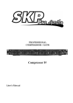
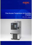
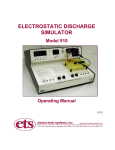
PRODUCT SPECIFICATIONS
Product Name
No
PREP.
Ion Migration Evaluation System
4063201000900
06. 25. 2008
Kusaka
REV.
This system continuously measures the insulation resistance of electronic components and
printed circuit boards under high temperature and high humidity, in order to evaluate insulation
reliability.
1. Product name
Ion Migration Evaluation System
2. Related documents
Product external view drawing 4063202000400
Connection unit external view drawing 4063202000500
3. Model
AMI−
−U−
Number of control channels
5: 5 control channels
25: 25 control channels
Total number of channels
025: 25 channels
050: 50 channels
075: 75 channels
100: 100 channels
125: 125 channels
150: 150 channels
4. Total number of channels and number of control channels
Selected
AMI–025–U–5
(25-channel)
AMI–050–U–5
(50-channel)
AMI–075–U–5
(75-channel)
AMI–100–U–5
(100-channel)
AMI–125–U–5
(125-channel)
AMI–150–U–5
(150-channel)
AMI–025–U–25
(25-channel)
AMI–050–U–25
(50-channel)
AMI–075–U–25
(75-channel)
AMI–100–U–25
(100-channel)
AMI–125–U–25
(125-channel)
AMI–150–U–25
(150-channel)
Selected
Selected
Selected
Remarks:
1
ESPEC CORP.
No.
4063201000900
5. Options
Selected
None
Selected
English specification
Selected
LAN-supported test management software (Number of licenses: 1)
This software enables the user to check test status and process data from a
PC connected to the LAN. For details, see the Optional Specifications.
Selected
Data processing software (With statistical processing capabilities)
Statistical processing enables a Weibull analysis from failure time data. For
details, see the Optional Specifications.
Selected
Measuring cable (3 m)
This cable replaces the standard 1.5 m cable. The new length is 3 m. For
details, see the Optional Specifications.
Selected
Scanner unit inter-connection unit extension cable (4 m from system)
This cable replaces the standard 2.5 m cable. The new length is 4 m. The
new cable extends from the rear of the system. For details, see the Optional
Specifications.
Selected
Power supply voltage
120V AC ±10%
Single-phase, 8.3A
Power supply voltage
220V AC ±10%
Single-phase, 4.5A
Power supply voltage
240V AC ±10%
Single-phase, 4.2A
* The standard specification is 100V AC, single phase 10 A.
A single phase, single winding type of step-down transformer is used.
Selected
High voltage impression(300V)
High voltage impression(500V)
The applied voltage for specimens increases the maximum.
2
ESPEC CORP.
No.
Selected
4063201000900
Number required
Test board rack type A
This optional rack efficiently tests the Surface Insulation Resistance(SIR) of
SIR test coupon type IPC-B-24. For details, See the Optional Specifications.
Selected
Number required
SIR test coupon type IPC-B-24
set(s)
This optional board works with the test board rack type A.
For details, See the Optional Specifications.
Note) One set consists of five test coupons.
6. Basic configuration
This system consists of a system controller, measurement unit and scanner.
6.1 System composition
(1) Cabinet rack
ESPEC
(2) System controller
DELL (OptiPlex Series *1)
(3) Monitor
DELL (15” TFT LCD)
(4) Test management software
ESPEC
(5) Data processing software
ESPEC
(6) OS (Preinstalled)
MICROSOFT (Windows XP® Professional)
(7) GPIB board (Built-into system controller) NATIONAL INSTRUMENTS (778032-0112)
(8) Digital I/O board (Built-into system controller)
INTERFACE (PCI-2768C)
(9) Uninterrupted power supply unit
APC (CS350)
(10) Stress power supply unit (Constant voltage stressing)
ESPEC
(11) Scanner unit for high withstand voltage and low current
ESPEC
(12) Electrometer
KEITHLEY INSTRUMENTS (6514)
(13) Connection unit (With 2.5 m cable)
ESPEC *2
(14) Measuring cable
① For positive stressing, 1.5 m
Colored single-wire cable with banana plug
② For negative stressing, 1.5 m
5-lead coaxial cable with 6-pin square coaxial plug
Measuring cables are heat resistant to 150˚C.
Over extended use, the signal label at the end of the cable may discolor, but this
discoloration has no effect on performance.
Model
Quantity
AMI–025–U–*
AMI–050–U–*
AMI–075–U–*
①
25
50
75
②
5
10
15
1
1
1
1
1
1
1
1
1
1
1
1
1
Remarks: *1 The system controller is subject to change without notice. The latest version available at the
time of order or an equivalent controller is provided.
*2 There are 25 channels per connection unit.
3
ESPEC CORP.
No.
Model
Quantity
4063201000900
AMI–100–U–*
AMI–125–U–*
AMI–150–U–*
①
100
125
150
②
20
25
30
“5” or “25” is inserted for *.
ESPEC *3
(15) Chamber monitor
1
6.2 Block diagram
The system is configured as shown below.
Cabinet rack
System controller
Uninterrupted power
supply unit
Heat resistant
measuring cable
Scanner unit for
high withstand
voltage and low
current
Digital I/O
GPIB
Environmental test chamber
(RS-485 specification)
Leak behavior mode
detection unit
Voltage stressing unit
Electrometer
Specimen
Coaxial cable
RS-232C
Chamber
monitor
Connection unit
RS-485
【System block diagram】
The environmental test chamber is outside the scope of these specifications.
6.3 Connection unit
The connection unit is provided to facilitate connections between this system
and specimens. It connects the measuring cable from this system to the
specimen cable.
6.3.1 Number of connectable channels by relay
25 channels per connection unit
6.3.2 Measuring cable
(1) Positive side
(2) Negative side
Heat resistant single-wire cable, L1.5 m
Heat resistant coaxial cable, L1.5 m
Remarks: *3 Adapter for RS-485 communications between the PC and environmental test chamber.
4
ESPEC CORP.
No.
4063201000900
6.3.3 Measuring cable working temperature range
-15 to +150˚C
6.3.4 Connection unit connection diagram
Measuring system
Scanner unit
for high
withstand
voltage and
low current
25-wire flat
cable x 1
Colored single-wire cable with
banana plug x 25
To specimen in
environmental test
chamber
6-pin square coaxial plug
(5-lead coaxial cable) x 5
Connection unit
Coaxial
cable x 25
Banana jack x 25
6-pin square coaxial plug x 5
【Connection unit connection diagram】
7. Specifications
7.1 Power supply
(1) Power supply voltage
(2) Power supply frequency
(3) Power supply leakage breaker
• Rated voltage
• Sensitivity current
• Trip time
• Rated current
(4) Power cable
• Cable length
• Cable end
100V AC±10%, single-phase, 10 A
50/60 Hz
100V AC
30 mA
Max. 0.1 sec
15 A
3m
3P socket plug (L, N, GND)
7.2 Guaranteed working environment
Temperature range: 5 to 35˚C (No dewing)
7.3 Outer dimensions
W 530 x H 1,750 x D 940 mm (Excluding projections)
7.4 Weight
The weight of the standard specification system is as follows.
Model
AMI–025–U–*
AMI–050–U–*
AMI–075–U–*
Weight
233 kg
234 kg
240 kg
Model
AMI–100–U–*
AMI–125–U–*
AMI–150–U–*
Weight
255 kg
261 kg
262 kg
“5” or “25” is inserted for *.
5
ESPEC CORP.
No.
4063201000900
8. Installation
8.1 Installation conditions: Install the system in the following environment.
• On a flat, level floor that is sturdy enough to support the system’s weight
• Where not subjected to excessive mechanical vibrations
• Where not exposed to direct sunlight
• Which is void of sharp temperature fluctuations
• Which is not dusty
• Which is not humid
• Away from flammables
• Where not exposed to combustible or corrosive gases
• Away from equipment that generates noise
8.2 Installation space
Secure a minimum 40 cm of space on the left, right and rear of the system.
Though space requirements on the side of the system are not strictly
enforced, always ensure enough space behind the system for a person to
pass.
8.3 Grounding
Ensure 100 Ω or less resistance against ground.
* To ensure safe system operation, ground the power cable.
9. Test performance
9.1 Measurement feature
(1) Stress power supply unit
① Stress voltage
② Minimum setting resolution
③ Impressed voltage accuracy
1.0 to 100V DC
0.1 V
± (0.7% of setting + 300 mV)
(2) Measurement equipment specifications
① Current measurement range
0.1fA to 20mA
② Minimum resolution
0.1fA
③ Measurement accuracy
±1.015% (20pA range FS)
(3) System measurement range and accuracy
(Including actual environmental effects)
① Resistance measurement range 1.0 × 10⁵ Ω to 1.0 × 10¹³ Ω (In 100 V stressing)
1.0 × 10³ Ω to 1.0 × 10¹¹ Ω (In 1 V stressing)
② DC measurement range
10pA to 1.0mA
* The resistance measurement range is determined by the DC measurement range and
applied voltage.
③ Resistance measurement accuracy
Accuracy is indicated at the end of the measuring cable.
[Measurement conditions]
Ambient temperature
23˚C±5˚C
Measurement mode
Long
Measurement range
Auto
Averaging (Times)
4
Charging time (sec)
60
* The above specifications do not apply to the first measurement after measurement start.
6
ESPEC CORP.
No.
4063201000900
(Ω)
1.0×10¹³
±300% to 500%
1.0×10¹²
±10%
11
1.0×10
1.0×10¹⁰
±5%
9
1.0×10
1.0×10⁸
1.0×10⁷
±3%
1.0×10⁶
1.0×10⁵
1.0×10⁴
±5%
1.0×10³
Immeasurability
1.0×10²
1.0×101
1
10
20
30
40
50
60
70
80
90
100
(V)
*・ When accuracy in the above table falls on a borderline, the lower accuracy or immeasurability
cell has priority.
・ Resistances of 10 kΩ (1.0 ×10⁴ Ω) and below cannot be measured because current exceeds
the established limit.
・ The above uniformity may not be produced in some system environments that customers have.
(4) Impressed voltage value in measurement
1.0 to 100V DC/0.1Vsteps
(5) Continuous test time
Max. 10,000 h
(6) Measurement time
(5-channel measurement/Max. 15 sec) + batch charging
time
Measurement time can be shorter depending on the type
of batch charging. Batch charging time is set in the test
setup.
* Charging time is unnecessary in the continuous stress voltage measurement mode. (This mode is
used only when the measurement voltage and stress voltage are the same.)
9.2 Leak behavior mode
(1) Mode overview
The leak behavior mode continuously monitors current leaks in-between samplings using a
separate circuit than that for periodic measurement via measurement equipment, and stops stress
voltage application and measurement on individual channels that exceed the limit. This mode
makes it possible to accurately pinpoint instantaneous short-circuit phenomena caused by ion
migration.
(2) Specifications
① Leak detection speed
Current flowing between samplings is detected at less than 100μsec.
7
ESPEC CORP.
No.
4063201000900
② Processing after leak detection
Testing is ended on channels where leaks are detected within 10 msec after detecting the
leak. And, the testing time when that leak occurred is recorded and saved in a file.
③ Leak detection setting range
Detectable leak setting range: 1μA to 500μA
Max. settable resolution:
1μA step
* A referential resistance is calculated from the stress voltage for the input leak current and
displayed in a separate area of the window.
9.3 Leak behavior check mode
(1) Mode overview
The leak behavior check mode performs limit evaluations the specified number of times
immediately after leak detection instead of ending testing, and determines whether to continue or
end measurement on the specific channel based on that evaluation. When this mode is ON,
channels where leaks were detected individually transition to the leak behavior check mode.
Normal measurement resumes and continues if resistance is recovered within the specified
number of cycles.
(2) Mode selection
The leak behavior mode can be turned ON or OFF from the test setup window of the Ion
Migration Evaluation System prior to starting the test.
① When the leak behavior mode is OFF
The resistance in-between samplings is evaluated only at the measurement interval set in
the test conditions and testing ends as set in the test conditions. (Only the leak behavior
mode can be turned ON.)
② When the leak behavior mode is ON
Testing transitions to the leak behavior check mode when triggered by the leak behavior
mode. All other test end conditions are invalidated such that testing ends only when the
number of check cycles or retries of the leak behavior check mode is reached.
* The leak behavior check mode cannot be turned ON if the leak current is not set when
registering test conditions.
(3) Specifications
<First measurement after transitioning to the leak behavior check mode>
Resistance is measured on channels where leaks are detected using measurement
equipment. If that resistance exceeds the limit, the leak behavior check mode is executed for
the specified number of cycles. If the limit is not exceeded, normal operation is restored.
<Leak behavior check cycles>
The leak behavior check mode continues to apply the stress voltage even after a leak has
been detected, measures resistance at the interval specified in “Holding Time” and evaluates
the measured resistance against limits. This evaluation is executed the number of cycles
specified in “Check Times”. If the resistance is recovered during this evaluation, testing
transitions back to normal measurement.
(Leaks are not redetected on channels during the leak behavior check mode.)
① “Holding Time”: Measurement interval in the leak behavior check mode
Sets the interval between resistance measurements after a leak has been
detected.
Setting range
1 to 60 min in 1-min steps
8
ESPEC CORP.
No.
4063201000900
② “Check Times”: Number of measurement cycles in the leak behavior check mode
Testing ends on channels where resistance is not recovered within the
number of measurement cycles set here. If resistance is recovered, the
cycle count up to that point is reset.
Setting range
1 to 10 times
③ Retries:
Number of retries in the leak behavior check mode
Sets the number of retries in the leak behavior check mode that resistance
can be recovered within the set number of check cycles and consequently
normal measurement restored. Testing ends when the number of retries
reaches the setting,
Setting range
1 to 1000 retries
* Holding time, check cycles and retries must be individually set on the test setup window
before testing starts.
(4) Test end condition of the leak behavior mode
① If the number of check cycles reaches the set number of cycles
Stress voltage application is stopped and testing ends on the concerned channel.
② If the number of retries reaches the set number of retries
Stress voltage application is stopped and testing ends on the concerned channel.
Reference
The leak behavior mode records individual channel behaviors while measurement
equipment is idle in-between normal periodic measurements. If leaks are simultaneously
detected on multiple channels, all behaviors may not be accurately pinpointed.
(5) Data processing
The insulation resistance measured during the leak behavior check mode after a leak detection
can be confirmed in leak records using the statistical processing application. This resistance can
also be linked to normal test data and plotted on graphs.
(6) Other
When testing ends because of sample leak behavior, testing for that particular sample is
interrupted and cannot be resumed. However, testing for other samples is as follows.
① Testing continues as long as the application is not closed while testing is interrupted or
resuming.
② If the application is closed while testing is interrupted, the number of leak behavior cycles and
retries reset and counting begins from 1. To continue testing in the leak behavior mode, do
not close the application while testing is interrupted.
9
ESPEC CORP.
No.
Transition in
resistance value
4063201000900
Holding time
Resistance
End (W hen 6 check
cycles are complete)
Evaluated leak
current
Time
Behavior check cycle
(Check cycles)
Periodic measurement
using measurement
equipment
[Measurement in the leak behavior mode]
10
ESPEC CORP.
No.
4063201000900
(7) Flowchart of continuous stress mode test after leak detection
Condition for leak behavior mode
selection (Stress voltage setting
= Measurement voltage setting)
Normal operation
Yes
Leak detected?
No
Insulation resistance measurement
Insulation resistance is saved in the test file.
If equal to or less than setting
Leak detection shuts OFF and
stressing continues.
If greater than
setting
Stressing continues.
Detection kept OFF ( ) min. *( )
is user-set from 1 to 60 min in 1
min steps.
However, the leak behavior
recode is saved.
Insulation resistance
measurement on affected
channel
Insulation resistance is
saved in the test file.
If greater
than setting
Comparison against
leak setting
Behavior check cycle
Comparison against
leak setting
If equal to or less
than setting
No
Has recovery cycles
reached set retries?
Check cycles not
reached
( ) check cycles *( ) is user-set
from 1 to 10 cycles.
Yes
Check cycles reached
Stressing OFF
(Only affected channel)
The change in insulation resistance recorded at this instance is linked to
and displayed on the normal test graph.
11
ESPEC CORP.
No.
4063201000900
10. System control specifications
This system software consists of software for managing tests and software for processing data.
10.1 Test management features
(1) Test conditions registration
① Test conditions setting and saving
② Test setup
User creates a test conditions file. Conditions are managed
as files.
User selects a test condition file and test channels.
(2) Measurement unit control
The below measurement conditions are set from the
system controller.
① Measurement mode
Can be selected from amongst Short, Medium and Long.
② Measurement averaging
Can be set from 1 to 10 cycles.
③ Charging time during measurement
(3) Schedule management
① Test duration
(4) Measurement interval
① Logarithmic interval
② Constant interval
③ Block interval
Can be set in 1 sec steps up to a max. 999 sec.
* If the stress voltage and measurement voltage differ and
measurement is performed while charging in the
specimen and measurement unit is unstable, the
measured value in that instant may differ from a
measured value obtained when charging was stable. In
such case, prolong charging time.
Measurements and data are managed by monitoring the
measurement time set for each test.
Can be set in 1 h steps up to a max. 10,000 h.
* Test setup and schedule can be set individually for each
control channel.
Can be selected from the below three modes.
log(t) = 0.1 or log(t) = 1 steps
0.1 h steps (0.1 to 9,999 h)
3 blocks, 0.1 h steps (Test duration must be set to 3 h or
① Absolute value (Ω)
more.)
* The minimum measurement interval shall vary according
to test conditions.
This system compares resistance of measured specimens
against a failure evaluation condition. Based on this result,
the system can automatically failure or continue testing for
the specific specimen.
Measured resistance that drops below the setting is taken
② Amount of change (Ω)
as the failure evaluation condition.
The amount of increase/decrease from the first measured
③ Rate of change (%)
resistance is taken as the failure evaluation condition.
The rate of increase/decrease from the first measured
④ Leak mode current (μA)
resistance is taken as the failure evaluation condition.
* All settings can be set to OFF.
(5) Failure evaluation
12
ESPEC CORP.
No.
4063201000900
(6) Test status display
Test status is displayed as follows.
• Operating status of linked chambers
• Test status of all groups
• Measured value and operating status for all channels
(7) Contact check
This feature checks whether specimens are open or not
and whether or not they are connected prior to starting the
test. The check is performed 1 time for a selected group
and the measured value is displayed on the main monitor.
However, this data can not be saved in the file.
Measurement voltage and charging time are the only
conditions that can be set for this feature.
This feature monitors the applied voltage for specimens.
When the applied voltage fluctuates ±10% of a setting
(8) Applied voltage monitor
value, the test of the applicable channels is terminated.
10.2 Data processing features
(1) Measurement data processing and management
① Primary data display
② Primary data graph projection
③ User-selected data record deletion
④ Data file conversion to text format (CSV file)
⑤ Record jump
⑥ Primary data file merging
* Primary data means measured data.
(2) Results output
The following items can be displayed. (Printing is possible with the optional printer.)
① Measured data and edited data
② Test conditions
③ Graph plots
Plots the change in insulation resistance against time.
• Change-over-time graph (X-axis: Time)
(Temperature and humidity data can be displayed at the same time.)
Graph projections have the following features.
• User-selected channel display
Plots maximum-average-minimum and average ±nσon graph.
• Resistance can be displayed as absolute value or rate of change.
• Time and resistance axes can be selected between linear and logarithmic
scales.
• Can paste graph window to clipboard.
• Can display data for a specific point by clicking on graph.
• Can project multiple data on same graph.
13
ESPEC CORP.
No.
4063201000900
10.3 Linked operation specification for environmental test chamber
A system of a maximum three environmental test chambers can be built using a network (RS-485).
Link environmental test chamber operation as explained in the User’s Manual. The chamber may not
operate correctly under other settings.
(1) Operation linkable environmental test chambers
* Chambers must be equipped with the RS-485 communication function to link with this
system. For linked operation with environmental test chamber other than the types
indicated below, contact ESPEC CORP.
① Temperature & Humidity Chamber
Platinous K Series
② Highly Accelerated Stress Test System (HAST Chamber)
EHS Series
* Chambers of the EHS Series cannot be controlled (starting, pausing, stopping and ending)
from this system.
③ Bench-Top Type Temperature & Humidity Chamber
SH/SU Series
(2) Temperature and humidity monitor
The temperature and humidity of the environmental test chamber are
monitored in sync with resistance measurements, and saved in the same
file as resistance measurement results.
(3) Alarm management
The system controller shuts OFF stress voltage and interrupts testing if an
alarm is detected by the environmental test chamber.
11. Power outage support
11.1 Uninterrupted power supply unit
The uninterrupted power supply unit prevents sampled data from being lost
in the event of a power outage by supplying backup power to the PC.
However, this uninterrupted power supply unit does not back up the entire
system. Also, the system controller does not shut the system down
automatically if a power outage occurs.
11.2 Power restoration
This system does not restore operations automatically after recovery from a
power outage.
12. Accessories
12.1 User’s Manuals
• Ion migration evaluation system (Basic operation)
• Data processing software (Reference)
12.2 System controller accessories
1
1
1 set
12.3 Monitor accessories
1 set
12.4 Uninterrupted power supply unit accessories
1 set
12.5 Measurement unit (6514) accessories
1 set
12.6 AMI setup CD
1
12.7 GPIB board accessories
1 set
14
ESPEC CORP.
No.
4063201000900
12.8 PPI board accessories
1 set
12.9 RS-485 cable (10 m)
1
12.10 Heat resistant measuring cable
1 set
12.11 Service manual (only for shipping specification)
1
13. Precautions in system use
Observe the following precautions to ensure safe stable system use.
13.1 Precautions in installation and connections
• Install the connection unit in a location where it is not directly exposed to hot vapor exiting from cable
ports. Direct contact with hot vapor may damage the connection unit.
• Do not touch the internal pins of the negative (black) connector of the connection unit with bare
hands. Foreign matter that adheres to the connector insulation can degrade system performance.
• Disconnect the positive side (red banana plug) of unused channels in test groups from the
connection unit. If left connected, voltage is applied to unused channels in the test group, which can
lead to damage and electric shock.
• Prevent sample pins and measurement (coaxial) cable wires from contacting the chamber or other
enclosures. Contact can result in incorrect data and equipment malfunction.
• Prevent the measuring cable wire and shielding from contacting metal parts inside the chamber.
Contact can destabilize measurements and throw off results. It can also divert voltage application
away from specimens and prevent migration testing.
• If the white insulation at the end of the measurement (coaxial) cable becomes dirty, clean with highly
pure isopropyl alcohol and dry adequately before use again.
13.2 Precautions for PCs
• Do not install other applications than those used by this system. Other applications may adversely
affect ESPEC’s applications.
• Do not change the default settings of the PC, including the screen saver and energy saving mode.
The PC is configured so that the applications operate stably before shipping. Changes may affect
the stable operation of ESPEC’s applications.
• Before using virus check software for connection to an intranet, make the necessary settings so that
virus check software cannot access the AMI folder in the C Drive. Do not connect the PC to the
internet. Internet connections may affect the stable operation of ESPEC applications.
• After long continuous tests, restart the computer and then start the next tests. Continuing to run the
PC after long continuous tests may affect the stable operation of ESPEC’s applications.
• Back up test data periodically as a defense against unexpected PC trouble.
13.3 Measurement interval setting
• Setting a short measurement interval for a system with many cables may interfere with normal
measurements. For the recommended measurement interval, see Chapter 5 Run and Operation
Procedures in the Basic Operation User’s Manual.
13.4 Settings for linked chambers
• Running chambers outside of the guaranteed operating range can cause dewing and other adverse
conditions that may prevent accurate measurements from being obtained. Run the chambers within
their guaranteed operating range.
15
ESPEC CORP.
J
I
H
G
F
E
D
C
B
A
2
3
Keyboard
Front view with connection unit installed on side
1
420
775
Front view
4
Cover
Connection unit
Monitor(TFT-LCD)
Indicator panel
5
940
NO.
DSG
DEPT.
NAME
CHK
S.E.D
7
APP
1/15
SCALE
3RD ANGLE PROJ
DIM mm
100
2008/06/05 2008/06/05
H.Jiten H.Jiten M.Kusaka
DRW
2008/06/05
Side view
Top view
H.Jiten
DATE
6
530
1750
REV
A3
DWG NO.
CODE
9
Q’ty
Power cable port
Rear cover
00
REV
Measurement unit spy window
40632020004
DWG NO.
0
REMARKS
External View Drawing
AMI-U
Rear view
TITLE
MATERIAL
DWG
SIZE
8
J
I
H
G
F
E
D
C
B
A
1
2
80
3
4
3
A-5
3
A-4
3
A-3
3
A-2
3
A-1
4
5
4
1
5
2
1
2
4
5
4
1
2
1
5
4
5
2
1
2
64
5
206
DRW
H.Jiten
NAME
CHK
S.E.D
7
APP
1/3
SCALE
3RD ANGLE PROJ
DIM mm
2008/06/05 2008/06/05
H.Jiten M.Kusaka
DEPT.
DSG
2008/06/05
NO.
H.Jiten
DATE
6
80
80
P39.5 4=158
160
160
REV
A3
DWG NO.
CODE
9
Q’ty
REMARKS
0
40632020005
DWG NO.
REV
00
Connection unit external view drawing
AMI-U
TITLE
MATERIAL
DWG
SIZE
8