1
Operation & Service Manual
823036
2/01
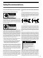
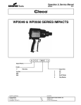
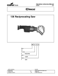
W2119 & W2120 SERIES IMPACTS
W
X
X
-
XXXX
-
X
Impact Wrench:
Handle:
Output Drive:
T
Inside Trigger
Outside Trigger
12
1 1/2"
S
Spline Drive (No. 5 Spline)
Tool Size:
2119
2120
NORTH AMERICA
EUROPE
CooperTools
P.O. Box 1410
Lexington, SC 29071
Cooper Power Tools GmbH & Co.
Postfach 30
D-73461 Westhausen
1
SafetyRecommendations
For your safety and the safety of others, read and understand
the safety recommendations before operating an impact wrench.
Never use the air hose for supporting, lifting, or lowering the tool.
Use a safety line or cable on the tool when working in elevated
areas.
Always wear protective equipment and clothing.
!
WARNING
Impact resistant eye protection
must be worn while operating
or working near this tool.
For additional information on eye protection, refer to Federal
OSHA Regulations, 29 CFR, Section 1910.133, Eye and Face
Protection, and ANSI Z87.1, Occupational and Educational Eye
and Face Protection. This standard is available from the American National Standards Institute, Inc., 11 West 42nd Street,
New York, NY 10036.
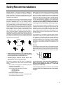
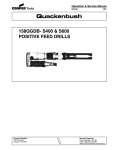
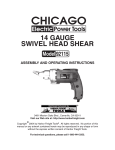
Tools with exposed throttles should not be used where obstructions can hold the throttle in the "on" position. An impact wrench
operating in reverse will move backwards as a nut is removed
and can trap an operator's hand, making it difficult to release an
outside trigger. Inside trigger or pistol grip tools are advised for
close quarter operation.
Outside Trigger
Rev.
Pistol Grip
Rev.
DO NOT USE!
!
CAUTION
Personal hearing protection is
recommended when operating
or working near this tool.
Hearing protection is recommended in high noise areas (above
85 dBA). Close proximity of additional tools, reflective surfaces,
process noises, and resonant structures can substantially contribute to the sound level experienced by the operator. Proper
hearing conservation measures, including annual audiograms
and training in the use and fit of hearing protection devices may
be necessary. For additional information on hearing protection,
refer to Federal OSHA Regulations, 29 CFR, Section 1910.95,
Occupational Noise Exposure, and American National Standards Institute, ANSI S12.6, Hearing Protectors.
• Gloves and other protective clothing should be worn as
required, unless they create a greater hazard.
• Do not wear loose fitting clothing, or clothing that may
restrict movement, become entangled or in any way
interfere with the safe operation of the impact.
Cleco impact wrenches are designed to operate on 90 psig (6.2
bar) maximum air pressure. If the tool is properly sized and
applied, higher air pressure is unnecessary. Excessive air
pressure increases the loads and stresses on the tool parts,
sockets, and fasteners and may result in breakage. Installation
of a filter-regulator-lubricator in the air supply line ahead of the
tool is highly recommended.
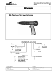
Before the tool is connected to the air supply, check the throttle
for proper operation (i.e., throttle moves freely and returns to
closed position). Being careful not endanger adjacent personnel, clear air hose of accumulated dust and moisture. Before
removing a tool from service or changing sockets, make sure
the air line is shut off and drained of air. This will prevent the tool
from operating if the throttle is accidently engaged.
OK
Only use sockets designed for use with impact wrenches. Never
use a hand tool socket on an impact wrench. Hand tool sockets
can break, resulting in a hazard from flying pieces. Inspect
sockets, retainers, and drives regularly for wear or damage, and
replace as necessary. Worn sockets reduce power, cause drive
wear, and increase the chance for breakage and should not be
used.
Impact wrenches equipped with the spline drive have an integral
socket retainer pin which may be depressed by a screwdriver or
similar tool when installing or removing a socket. Tools with
square drives 3/4" and larger use an aor- ring and pin for socket
retention. Retainers—either pin or integral—should be properly
engaged to prevent dropping sockets into lower working levels.
Always use socket retainer components recommended by the
socket manufacturer. Never substitute wire, nails, or welding
rods for retaining pins because they are dangerous if thrown
from the tool at free speed, or if the protruding nail or wire is
accidently grasped by the operator.
!
WARNING
Repetitive work motions and/or vibration
may cause injury to hands and arms.
Use minimum hand grip force consistent
with proper control and safe operation.
Keep body and hands warm and dry.
Avoid anything that inhibits blood circulation.
Avoid continuous vibration exposure.
Keep wrists straight.
Avoid repeated bending of wrists and hands.
Some individuals may be susceptible to disorders of the hands
and arms when performing tasks consisting of highly repetitive
motions and/or exposure to extended vibration. Cumulative
trauma disorders such as carpal tunnel syndrome and tendonitis may be caused or aggravated by repetitious, forceful exertions of the hands and arms. Vibration may contribute to a
condition called Raynaud's Syndrome. These disorders develop gradually over periods of weeks, months, and years. It is
2
SafetyRecommendations
•
Stressful postures should be avoided. Select a tool
appropriate for the job and work location.
The following suggestions will help reduce or moderate the
effects of repetitive work motions and/or extended vibration
exposure.
• Use a minimum hand grip force consistent with proper
control and safe operation
• Keep body and hands warm and dry
• Avoid anything that inhibits blood circulation
—Smoking Tobacco
—Cold Temperatures
—Certain Drugs
• Keep wrists as straight as possible
• Avoid highly repetitive movements of hands and wrists,
and continuous vibration exposure
WARNING
!
OVER
Repetitive work motions and/or vibration
can cause injury to hands and arms.
Use minimum hand grip force consistent with
proper control and safe operation.
Keep body and hands warm and dry.
Avoid anything that inhibits blood circulation.
Avoid continuous vibration exposure.
Keep wrists straight.
Avoid repeated bending of wrists and hands.
CAUTION
!
Personal hearing protection is
recommended when operating
or working near this tool.
Hearing protection is recommended in high noise
areas (above 85 dBA). Close proximity of other
tools, reflective surfaces, process noises, and
resonant structures can substantially contribute
to the sound level experienced by the user.
WARNING
• Tasks should be performed in such a manner that the
wrists are maintained in a neutral position, which is not
flexed, hyperextended, or turned side to side.
Warnings
The warnings found on these tools are an essential part of the
product. Warnings should be checked periodically for ligibility.
Replace warnings when missing or when the information can no
longer be read. Replacements can be ordered as any spare
part.
!
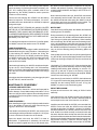
GOOD POSTURE
This information is a compilation of general safety practices
obtained from various sources available at the date of production. However, our company does not represent that every
acceptable safety practice is offered herein, or that abnormal or
unusual circumstances may not warrant or require additional
procedures. Your work may require additional specific safety
procedures. Follow these procedures as required by your
company.
Impact resistant eye protection
must be worn while operating
or working near this tool.
BAD POSTURE
Also note that various tool wraps are available from a number
of different manufacturers. Like gloves, these wraps are also
intended to reduce and moderate the effects of extended
vibration exposure. They vary widely in design, material, thickness, vibration reduction, effectiveness, and durability, so consideration must be given to choosing the proper wrap for the
specific application.
Read Operating Instructions carefully. Follow
the Safety Recommendations for your safety
and the safety of others.
Tool operators should be aware of the following warning signs
and symptoms so that a problem can be addressed before it
becomes a debilitating injury. Any user suffering prolonged
symptoms of tingling, numbness, blanching of fingers, clumsiness or weakened grip, nocturnal pain in the hand, or any other
disorder of the shoulders, arms, wrists, or fingers is advised to
consult a physician. If it is determined that the symptoms are job
related or aggravated by movements and postures dictated by
the job design, it may be necessary for the employer to take
steps to prevent further occurrences. These steps might include, but are not limited to, repositioning the workpiece or
redesigning the workstation, reassigning workers to other jobs,
rotating jobs, changing work pace, and/or changing the type of
tool used so as to minimize stress on the operator. Some tasks
may require more than one type of tool to obtain the optimum
operator/tool/task relationship.
Work gloves with vibration reducing liners and wrist supports
are available from some manufacturers of industrial work
gloves. These gloves are designed to reduce and moderate the
effects of extended vibration exposure and repetitive wrist
trauma. Since they vary widely in design, material, vibration
reduction, and wrist support qualities, it is recommended that
the glove manufacturer be consulted for gloves designed for
your specific application. WARNING! Proper fit of gloves is
important. Improperly fitted gloves may restrict blood flow
to the fingers and can substantially reduce grip strength.
Do not remove this tag until
the operator of this tool has
read these safety precautions.
presently unknown to what extent exposure to vibrations or
repetitive motions may contribute to the disorders. Hereditary
factors, vasculatory or circulatory problems,exposure to cold
and dampness, diet, smoking and work practices are thought to
contribute to the conditions.
869976
For more information, see the latest edition of ANSI B186.1,
Safety Code for Portable Air Tools, available from the
American National Standards Institute, Inc., 11 West 42nd
Street, New York, NY 10036.
These operating instructions and service manual should
accompany tool if it is subsequently sold or ownership is
changed.
3
GENERAL INFORMATION
AIR SUPPLY
Thetool isdesigned to operate on 90 psig (6.2 bar) airpressure
(measured at the tool air inlet with the tool running) using a
1/2" (12.7mm) hose up to 8' (2.4m) in length. An automatic
in-line filter-lubricator is highly recommended to supply the
tool with cleanlubricated air. This will keepthe tool in sustained operation and increase its service life.
The air hose should be cleared of accumulated dirt and
moisture, then one (1) teaspoon (5ml) of 1 OW machine oil
should be poured into the tool's air inlet before connection
the hose to the tool.
IMPORTANT: If a puick-disconnect coupling is used with
the tool, it should be separated from the tool by a whip hose.
All tools and hoses should be installed by trained, competent personnel. Hoses and fittings should be inspected
regularly for worn or damaged areas and replaced if necessary.
LUBRICATION
An automatic in-line filter-lubricator is recommended as it
increases tool fif e and keeps the tool in sustained operation. The in-line lubricator should be regularly checked and
filled with a good grade of 1 OW machine oil. Proper
adjustment of the in-line lubricator is performed by placing
a sheet of paper next to the exhaust ports and holding the
throttle open approximately 30 seconds. The lubricator is
properly set when a light stain of oil collects on the paper.
Excessive amounts of oil should be avoided. In the event an
in-line lubricator is not used, the oil reservoir in the handle
should be utilized.
The oil reservoir marked "30W oil" should not require
attention until thetool istorn down for inspection purposes;
however, if the tool is on the application for an unduly long
period of time, the plug should be removed and the reservoir
checked for the presence of oil. If oil is required, approximately 1-1/4 fluid ounces (40ml) of 30W oil should be added
to the oil reservoir.
front of the motor unit. The anvil housing may need to be
rotated to clear the anvil and hammer lugs.
The impact wrench is now separated into four (4) basic
assemblies. See the following paragraphs for commplete
disassembly instructions on these assemblies
ANVIL HOUSING
For better performance, it is recommended that the anvil
housing seal, No. 867993, be replaced during each repair.
The seal may be removed by prying it out with a screwdriver.
Should the anvil housing bushing, No. 861602, need replacing, the housing seal will have to be removed as outlined
above Press the housing bushing out the rear of the housing
using a bushing driver 2-3/16" in diameter.
IMPACT MECHANISM
Clamp the hammer, No 867969, horizontally in a softjawed
vise and drive the anvil* away from the hammer using a soft
hammer This will allow the anvil pin, No 867994, spring clip,
No 867964. and hammer spring No. 867984 to be removed
from the front of the cam shaft, No 867973
Remove the hammer from the vise and slip the cam shaft
and related components out of the rear of the cam, No.
867991. Remove the shock absorber, No. 867980, (slight
press fit) from the rear of the cam shaft. This will allow the
insulator, No. 869012, butt plate, No. 869011, cam roller,
No. 869278, and cam roller shaft, No867979, to be removed
from the cam shaft.
Slip the cam, No. 867991, out of the rear of the hammer,
being careful not to lose the timing pin, No. 867966.
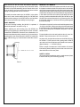
*NOTE: On the spline drive anvils, should any of the socket
retainer parts need replacing, a 5/32" hole should be drilled
in the socket retainer plunger, No. 867950, as shown in
Figure 3. Insert a pin punch in the drilled hole and lightly tap
the punch under the socket retainer pin, No. 867951. Pry on
the punch to pop the pin out of its pocket in the plunger.
STORAGE
In the event that it becomes necessary to store the tool for
an extended period of time (overnight, weekend, etc.), it
should receive a generous amount of lubrication atthat time
and again when returned to service. The tool should be
stored in a clean and dry environment.
MAINTINANCE - DISASSEMBLY
GENERAL - ALL MODELS
Disconnect the tool from the air supply and unscrew and
remove the four (4) nuts, No. 865006; then remove the
handle assembly, reversing valve, No. 869008, gasket, and
the motor clamp seal, No. 869001, from the rear of the
motor unit.
Drive the four (4) housing bolts, No. 869066, out the front of
the motor unit. Removing the anvil housing, No. 861605, will
allow the complete impacting mechanism to slip out the
4
MOTOR UNIT
Set the front of the housing, No. 869744, on a cylinder (4112'' I.D. x 5'' long) and using a suitable driver (2-1/8" O.D.)
drive the rotor out of the rear rotor bearing, No. 867995. This
will remove the front bearing plate, No. 867985, six (6) rotor
blades, No. 867975, and rotor from the housing. Invert the
housing on the fixture and use the rotor to drive the rear
bearing plate assembly from the housing. The cylinder
should not be removed from the housing unless replacement is necessary. If cylinder replacement is necessary, a 45/32" O.D. bushing driver (with a suitable relief for the
alignment key, No. 867981) should be used to press the
cylinder out of the housing.
Remove the rotor bearings, No. 867995, from the bearing
plates for inspection. For better performance, it is recommended that the rotor shaft seals, No. 867996, be replaced
during each repair.
NOTE: UNLESS THE "0" RINGS, NO. 844309, LOCATED
ON THE O.D. OF THE BEARING PLATE ARE SEVERELY
DAMAGED, THEY SHOULD NOT BE REMOVED. IF REPLACEMENT IS NECESSARY, REPLACEMENT "0" RINGS
SHOULD BE INSTALLED WITH A FAST CURE CONTACT
ADHESIVE ("LOCTITE" 404).
For cleaning and inspection of the three (3) muffler plates,
No. 869004, unscrew the retainer screw, No. 883695.
HANDLE ASSEMBLIES
Both the inside and outside trigger handle assemblies are
disassembled using the same procedure. Unscrewing the
air inlet bushing, No. 864972, will allow the "0"ring, No.
863009, air inlet screen, No. 843656, throttle valve spring,
No. 864973, throttle valve No. 867974, throttle valve seal,
No. 867977, and throttle valve pin, No. 867982, to be
removed from the handle.
If the throttle pin bushing, No. 864975, should need replacing, tap. the I.D. of the bushing with a 114"-20 thread tap.
Insert a 114-20 bolt of the appropriate length and clamp the
bolt in the vise. Drive the handle away from the vise using a
soft mallet.
If the trigger should need replacing, only the trigger pin (solid
pin), No. 832125, need be removed.
MAINTENANCE - REASSEMBLY
CLEANING AND INSPECTION
All parts should be cleaned in a solvent and inspected for
wear or damage. If rotor blades measure less than 7116 on
either end, they should be replaced. Rotor bearings should
be replaced if they feel rough after cleaning or show excessive looseness.
HANDLE ASSEMBLY
When instailing the trigger use a pin slightly smaller than the
hole in the handle to locate the trigger when driving the
trigger pin, No 832125. into the handle.
If the throttle valve bushing No 864975, was removed, the
new bushing should be pressed in to a depth of 1 15/16" plus
or minus 1/64 from the bottom face of the handle.
Inspect the throttle valve seal, No, 867977, for wear or
deterioration. If replacement is necessary, the new seal
should be pushed (cupped face first) on the throttle valve,
No. 867974, from the tapered end. Inspect the "O"-ring, No.
863009, and replace if necessary. Clean the threads on the
air inlet bushing, No 864972, and apply "LOCKTITE" No. 271
to the threads.
Now install the throttle valve pin, No 867982, and throttle
valve assembly into the handle. Place the inlet air screen,
No. 843656, arid throttle valve spring, No. 864973, in the air
inlet bushing and screw the bushing into the handle. The
bushing should be torqued to 80 It lbs. minimum.
MOTOR UNIT
Insert the three (3) muffler plates. No. 869004, and install the
retaining screw, No. 883695.
During reassembly of the bearing plates, No. 867985, the
rotor shaft seals, No. 867996, should be installed with their
"lips'' facing out (visible after installation). When installing
the rotor bearings, No. 867995, press on the bearing's outer
race. Lubricate both the seals and rotor bearings with 30W
oil before assembly into the motor unit. Inspect the "O"-ring,
No. 863096, and replace if necessary. This "O"-ring is used
only on the front bearing plate (both bearing plates are
identical).
If the cylinder was removed, the new cylinder (with alignment
key, No. 867981, in place) should be pressed in from the rear
of the motor housing to a depth 5/8" from the rear face of the
housing.
Lubricate the "O"-rings on the O.D. of the rear bearing plate
assembly and press the assembly into the housing. When
installing either bearing plate assembly, be sure the "O"rings line up with the air ports in the housing. Invert the
housing and install the rotor with the end stamped ''REAR"
into the rear rotor bearing, No. 867995.
Insert the six (6) rotor blades, No. 867975, then lubricate the
"O''-rings on the front bearing plate assembly and press the
assembly into the housing. NOTE: Be sure '0--ring, No.
863096, is in place on the front bearing plate.
IMPACT MECHANISM
All parts should receive a thin coating of 30W oil before
assembly.
Insert the timing pin, No. 867966, into the recess located on
the small O.D. of the cam, No. 867991, and then install the
cam and pin into the rear of the hammer, No. 867969.
Install the cam roller shaft, No. 867979, in the cam shaft, No.
867973. Put the cam roller, No. 867978, on the roller shaft
and slip the butt plate, No. 869011, insulator, No. 869012,
and shock absorber, No. 867980, onto the rear of the cam
shaft. Hold the cam shaft vertically on the work bench with
the shock absorber down and tap the end of the cam shaft
with a soft mallet to seat the cam shaft in the shock absorber.
Slip the cam shaft and related components through the cam
and hammer assembly. Install the hammer spring, No.
867984 spring clip, No. 867964, and anvil pin, No. 867994,
5
onto the front of the cam shaft and hammer assembly.
Rotate the spring clip to accept the anvil pin and then install
the anvil on top of the assembly (be sure the slot in the anvil
lines up with the anvil pin) and drive the anvil down until the
spring clip engages the recess in the anvil.
To install the socket retainer pin, No 867951, in the spline
drive anvil, insert socket retainer spring, No. 867949, and
socket retainer plunger, No. 867950 into the anvil and then
drive the socket retainer pin radially into the plunger.
ANVIL HOUSING
If the anvil housing bushing, No 861602, is replaced, it
should be pressed in as shown in Fig. 4.
When replacing the anvil housing sea), No 867993, the
housing bore should be cleaned with a solvent and then
coated with ''PERMATEX" Aviation Form-A-Gasket No. 3H,
and then be allowed to air dry at least four (4) minutes before
pressing in the seal. Press the seal in with its "lip" toward the
bore of the housing (''Lip'' should not be visible after assembly.)
GENERAL- ALL MODELS
Coat the hammer and rotor splines with 30W oil and insert
the impact mechanism into the front of the rotor Lubricate the
anvil housing seal and bushing with 30W oil and install on the
unit being sure the contour of the anvil housing matches that
of the motor housing The anvil and hammer lugs should be
in line with the recess in the make-up lip located in the anvil
housing. Install the dead handle bracket, No. 867990, on the
left side of the tool and insert the four (4) housing bolts. Tap
the bolts with a hammer until the anvil housing seats against
the motor housing.
Clarnp the tool vertically in a vise and install the gasket Insert
-0--ring, No. 847981, into the reversing valve bore and install
the reversing valve, No. 869008. Apply a thin coat of grease
to the motor clamp seal, No 869001, and place it into the
handle recess.
Put the handle on the tool and install the four (4) nuts, No.
865006. Torque these nuts to 20 ft. lbs. minimum.
Lay the tool on its right side and remove the 30W oil fill plug,
No. 867801. Fill the reservoir with a good grade of 30W oil
up to the level of the fill indicator pin located in the reservoir
(approximately 1 - 1-1/4 fluid Ounces).
Place a couple of teaspoons of 10W machine oil in the air
inlet bushing before attaching the air hose to ensure immediate lubrication of all motor parts.
SAFETY CHECK
All tools should be tested after repair or replacement of parts
to assure that they are functioning properly.
6
7
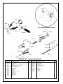
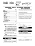
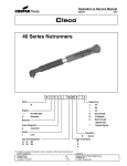
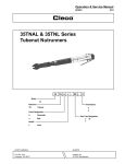
PARTS LIST — IMPACT MECHANISM
PART NO.
842290
861602
861605
867949
867950
867951
867964
867966
867969
867970
867973
867976
867978
867979
867980
867983
8
NAME OF PART
Support Handle
Anvil Housing Bushing (incl. 867976, 867983, 867987,
867988)
Anvil Housing (incl. 861602, 867993)
Socket Retainer Spring
Socket Retainer Plunger
Socket Retainer Pin
Spring Clip
Timing Pin
Hammer
#5 1-5/8" Spline Drive Anvil
Cam Shaft
Thrust Race
Cam Roller
Cam Roller Shaft
Shock Absorber
Cushion
QTY.
PART NO.
NAME OF PART
QTY.
1
1
867984
867987
867988
867990
867991
867993
867994
869010
869011
869012
869066
Hammer Spring
Thrust Bearing
Thrust Race
Support Handle Bracket
Cam
Anvil Housing Seal
Anvil Pin
1-1/2" Sq. Dr. Anvil
Butt Plate
Insulator
Housing Bolt
1
1
1
1
1
1
1
1
1
1
4
1
1
1
1
1
1
1
1
1
1
1
1
1
1
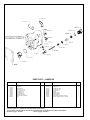
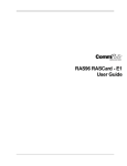
PARTS LIST — MOTOR UNIT
PART NO.
863096
863637
865004
867971
867975
867981
867985
867995
NAME OF PART
O-ring 3-1/4" X 3-1/2"
Wear Plate Pin
Wear Plate
Cylinder (W-2120)
Rotor Blade
Alignment Key
Bearing Plate (incl. 844309)
Rotor Bearing
QTY.
PART NO.
1
1
1
1
6
1
2
2
867996
869001
869004
869596
869635
869744
883695
NAME OF PART
Rotor Shaft Seal
Motor Clamp Seal
Muffler Plate
Rotor
Cylinder (W-2119)
Housing (incl. 863637, 865004, 869004,883695)
Retainer Screw
QTY.
1
1
1
1
1
9
PARTS LIST — HANDLES
PART NO.
203282
832125
843656
844303
847981*
863009
864387
864972
864973
864975
865006*
NAME OF PART
Washer
Trigger Pin
Air Inlet Screen
O-ring 3/16" X 5/16"
O-ring 1-3/8" X 1-1/2"
O-ring 3/4" X 7/8"
10W Oil Fill Plug
Air Inlet Bushing
Throttle Valve Spring
Throttle Valve Pin Bushing
Nut
QTY.
PART NO.
2
1
1
1
1
1
1
1
1
1
4
867801
867974
867977
867982
567998
867999*
869000
869008*
869009
869740
869743
NAME OF PART
30W Oil Fill Plug
throttle Valve
Throttle Valve Seal
Throttle Valve Pin
Inside Trigger
Gasket
Outside Trigger
Reversing Valve
Trigger Stop Pin
Inside Trigger Handle (incl. 864975)
Outside Trigger Handle (incl. 864975)
*Denotes parts not included in subassemblies listed below.
The complete handle can be ordered as a subassembly using the part numbers listed below.
Outside Trigger - 861867
Inside Trigger - 861863
10
QTY.
1
1
1
1
1
1
1
1
1
1
1
NOTES
11
CooperTools
670 Industrial Drive
Lexington, SC 29072
Phone: (803) 359-1200
Fax: (803) 359-2013
www.cooperindustries.com
12