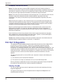
1
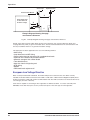
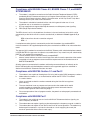
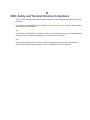
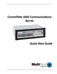
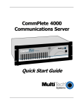
CommPlete 4000 Communications Server
User Guide
CommPlete 4000 Communications Server
User Guide
S000348A, Revision A
This publication may not be reproduced, in whole or in part, without prior expressed written
permission from Multi-Tech Systems, Inc. All rights reserved.
Copyright © 2004, by Multi-Tech Systems, Inc.
Multi-Tech Systems, Inc. makes no representations or warranties with respect to the contents hereof
and specifically disclaims any implied warranties of merchantability or fitness for any particular
purpose. Furthermore, Multi-Tech Systems, Inc. reserves the right to revise this publication and to
make changes from time to time in the content hereof without obligation of Multi-Tech Systems, Inc.
to notify any person or organization of such revisions or changes.
Record of Revisions
Revision
A
Date
Description
05/21/04
Replacing printed User Guide and including new SBC (IAC-F969
Series).
Patents
This product is covered by one or more of the following U.S. Patent Numbers: 5.301.274; 5.309.562;
5.355.365; 5.355.653; 5.452.289; 5.453.986. Other Patents Pending.
TrademarksTrademarks of Multi-Tech Systems, Inc. are as follows: CommPlete, RASExpress,
MultiExpressFax, and the Multi-Tech logo.
CompuServe is a trademark of CompuServe, Inc.
Multi-Tech Systems, Inc.
2205 Woodale Drive
Mounds View, Minnesota 55112
(612) 785-3500 or (800) 328-9717
Fax (612) 785-9874
Tech Support (800) 972-2439
Internet Address: http://www.multitech.com
2
CommPlete 4000 Communications Server User Guide
Contents
System Overview ...................................................................................... 5
Product Overview ................................................................................................................................. 5
RASExpress .................................................................................................................................. 6
Documentation Set Overview ............................................................................................................... 6
Technical Specifications ....................................................................................................................... 7
Chassis .......................................................................................................................................... 7
Power Supply ................................................................................................................................. 7
Dimensions .................................................................................................................................... 7
Environmental ................................................................................................................................ 7
Chapter 2 - Installing Your CommPlete 4000 .......................................... 8
Unpacking ............................................................................................................................................ 8
Safety Warnings ................................................................................................................................... 8
Rack Mounting ..................................................................................................................................... 8
Cable Connections ............................................................................................................................... 8
SBC Board Cabling ........................................................................................................................ 9
ISI Board Cabling ......................................................................................................................... 10
Serial Card Upgrades .................................................................................................................. 11
Powering Up ....................................................................................................................................... 12
Chapter 3 - Getting Started with RASExpress...................................... 13
What you need to start ................................................................................................................. 13
Accessing RASExpress ............................................................................................................... 13
Method A. Do All Configuration using Terminal or Auxiliary PC .................................................... 14
Method B. Start Configuration with Terminal, Finish Configuration on Client PC ......................... 16
Chapter 4 - Hardware removal/Replacement ........................................ 18
Disconnecting Cables and Removal from Enclosure .......................................................................... 18
Card Cage Removal/Replacement ..................................................................................................... 19
Board Removal and Replacement .................................................................................................... 21
Removing SBC Board ................................................................................................................. 21
Removing ISI Boards ................................................................................................................... 22
Hard Disk Drive Removal/Replacement ............................................................................................. 22
Floppy Disk Drive Removal/Replacement .......................................................................................... 23
CDROM Removal/Replacement ........................................................................................................ 23
Power Supply Removal/Replacement ................................................................................................ 24
Chapter 5 - Troubleshooting ................................................................... 25
Troubleshooting .................................................................................................................................. 25
Diagnostic Tests ................................................................................................................................. 26
Chapter 6 - Service, Warranty, and......................................................... 27
Technical Support ................................................................................... 27
Limited Warranty ................................................................................................................................ 27
Addendum for North American Products ..................................................................................... 27
Addendum for International Products ........................................................................................... 28
Out of Warranty Repair Costs ...................................................................................................... 28
On-line Warranty Registration ...................................................................................................... 28
Technical Support .............................................................................................................................. 28
Recording CommPlete 4000 Information .................................................................................... 28
Contacting Technical Support ...................................................................................................... 29
Service ........................................................................................................................................ 29
Ordering Accessories ......................................................................................................................... 29
CommPlete 4000 Communications Server User Guide
3
Appendices .............................................................................................. 30
Appendix A—Back Panel Connector Pinouts ..................................................................................... 30
Appendix B—Regulatory Information ................................................................................................. 35
FCC Regulations for Telephone Line Interconnection ......................................................................... 35
Canadian Limitations Notice ........................................................................................................ 36
Compliance with BABT Requirements ............................................................................................... 36
European Low Voltage Directive .................................................................................................. 38
Compliance with BS6305 Clause 6.2, BS6320 Clause 7.2, and BABT/SITS/82/005S/D .............. 38
Compliance with BS6789: Section 3.1 and Part 2 ........................................................................ 38
Compliance with BS6328 Part 1 .................................................................................................. 39
EMC, Safety, and Terminal Directive Compliance ............................................................................... 39
4
CommPlete 4000 Communications Server User Guide
Chapter 1 - System Overview
System Overview
The CommPlete™ 4000 Communications Server is a single-segment, rack mountable
communications server. It is customized for dedicated turnkey operation of LAN-based
communications and remote access server functions. The CommPlete 4000 is a general purpose,
turnkey communications server that easily interfaces to any existing Novell, Windows NT, or IP
network.
Figure 1-1. CommPlete™ 4000 Communications Server
Product Overview
The CommPlete 4000 is a ruggedized, highly expandable 19" rack mount device that includes a builtin hard drive, 3.5" floppy drive, and a slot for a CD-ROM drive. It has five circuit-board slots: four are
PCI compatible, and one accommodates either a PCI or ISA card. (Each CommPlete 4000 model is
shipped with a Network Interface Card and a MultiModem ISI card. These occupy two slots, leaving
three slots for expansion cards.) A separate slot supports the single board computer (SBC) that is
the heart of the system. A user configurable card cage allows for up to 32 V.90 (56kbps, KFlex)
internal modems or up to 32 high speed serial ports. The CommPlete 4000 is shipped with factoryinstalled RASExpress server software for remote-access functionality. Each CommPlete 4000 has a
default configuration that allows it to boot as a RAS unit.
The four CommPlete 4000 models differ according to the serial interface card used. The different
serial interface cards offer, variously, serial ports for external modems, built-in modems, or built-in
modems and terminal adapters:
Model CC4S-8 with the ISI4608PCI or ISI4608UPCI serial card -- has serial port connections for
eight external modems.
Model CC4M-8 with the ISI5634PCI/8 or ISI5634UPCI serial card -- has eight built-in modems
Model CC4H-4S with the ISIHP-4S serial card -- provides four ISDN terminal adapters using the S
interface as well as eight analog modems (allowing eight concurrent sessions)
Model CC4H-4U with the ISIHP-4U serial card -- provides four ISDN terminal adapters using the
U interface as well as eight analog modems (allowing eight concurrent sessions)
The CommPlete 4000 has expansion capability for up to three additional MultiModem ISI circuit cards
(for additional modems/TAs). When multiple serial-interface cards are used, the CommPlete
accommodates or includes as many as 32 communications devices. While it is most common to use
multiple ISI cards all of the same type, you can equip a single CommPlete 4000 unit with more than
one type of ISI card.
CommPlete 4000 Communications Server User Guide
5
Chapter 1 - System Overview
RASExpress
The CommPlete 4000 is equipped with factory installed RASExpress, an advanced remote access
software that enables network managers to configure and manage remote servers via web browsers,
through Telnet over an IP network, and via a GUI manager over both IP and IPX networks. Through
an a special software package bundled with the CommPlete 4000, RASExpress can also be
interfaced to standard Radius Authentication functionality (which resides on a separate PC). Radius
Authentication ensures security against unauthorized server access, and includes an integrated
Telnet server and Client. Built-in R log protocol support permits remote log-in to all hosts on the
network and RASExpress can facilitate remote software upgrades via standard TFTP protocol.
CommPlete 4000
Single Processor
Data Communications Server
Terminals
EtherNet
LAN
RASExpress
Software
Ethernet Concentrator
SBC
Intelligent Serial
Interface Cards
ISI5634PCI/8
ISI5634PCI/8
ISI5634PCI/8
Ethernet 10BASET Concentrator
Model EN516TP/CA Active Hub for UTP Networks
1
2
3
4
5
6
7
8
9 10 11 12 13 14 15 16
Dial-Up
Lines
ISI5634PCI/8
Printer
Print
Server
File
Server
Figure 1-2. Typical RASExpress Application
Additional noteworthy features include:
•
Support for DHCP, a time saving feature that dynamically allocates IP addresses instead of
requiring network managers to allocate them manually
•
Built-in SNMP agent enables third-party SNMP manager to administer the box
•
Support of IP and IPX header compression and IP VJC header compression for increased
performance
•
Call back support for Windows 95 client
•
Remote Access Security on a per use basis for accessing IP only, IPX only, or both IP and IPX
•
Keyboard or mouse operation
•
Standard or User-defineable cover page
•
Built-in web, telnet, and FTP access
Documentation Set Overview
The CommPlete 4000 documentation includes individual hardware and software manuals available
on the CD. Individual titles in your CommPlete 4000 documentation include the following:
•
CommPlete 4000 Quick Start Guide
•
System Overview and Chassis Manual
•
Single Board Computer User Guide
•
RASExpress User Guide
•
RADIUS Server User Guide
•
Serial Card documentation: ISI4608PCI, ISI4608UPCI, ISI5634PCI/8, ISI5634UPCI/8,
ISIHP-2S/2U/4S/4U/4SD
6
CommPlete 4000 Communications Server User Guide
Chapter 1 - System Overview
Technical Specifications
The CommPlete 4000 conforms to the following technical specifications.
Chassis
•
6-slot PCI/ISA backplane
•
SBC
•
One half-height 1.44Mb 3½-inch floppy disk drive
•
One half-height IDE hard disk drive
•
One power supply
•
Power on/off switch on front panel with built in power LED.
•
Full security locking
•
Intelligent Serial Interface card with or without modems/TAs (ISI4608PCI,ISI4608UPCI,
ISI5634PCI/8, ISI5634UPCI/8, ISIHP-4S, or ISIHP-4U)
Power Supply
AC Input
•
Power requirement: 100-120/220-240V; 6A/3A (RMS) selectable by slide switch
•
Frequency: 50-60 Hz
•
Efficiency: >65% @ full load, nominal line
DC Output
•
Output:
+5 @ 25A
+12 @ 10A
-5 @ 0.5A
-12 @ 0.5A
•
Inrush current: <30A peak @ 115VAC, cold start at 25o C
•
Line regulation: +/- 5% at full load for +/-5V, +/-12V, +/-10% for -12V
•
Hold Time: 12ms at full load @ 115VAC
Note: 3.3 volts, DC, is available at PCI expansion slots on the backplanes.
Dimensions
•
Height: 5.25 inches
•
Width: 19 inches
•
Depth: 17 inches
•
Weight: 31 lbs. (14kg)
Environmental
0–40o C
•
Temperature:
•
Humidity: 10–90% RH noncondensing
•
Fan Rating: 25 cfm
CommPlete 4000 Communications Server User Guide
7
Chapter 2 - Installing Your CommPlete 4000
Chapter 2 - Installing Your CommPlete 4000
This chapter explains how to set up and connect cables for the CommPlete 4000. This product is
ready to be connected to the end-user's Ethernet concentrator. It is preconfigured to operate as a
communications server. The operator must make modem/terminal-adapter connections, link up the
VGA monitor and keyboard, boot the system, and enter some basic information. To connect the
cables to the SBC or ISI board, see the Cable Connections section of this chapter.
Unpacking
Check the items on the CommPlete 4000 shipping list to ensure that you have received the correct
options and accessories. Unpack the unit and inspect it for visible shipping damage. If damage is
observed, do not power-on the unit; contact Multi-Tech's Tech Support for advice. If no damage is
observed, place the CommPlete 4000 in its final location.
Safety Warnings
•
Never install telephone wiring during a lightning storm.
•
Never install telephone jacks in wet locations unless the jack is specifically designed for wet
locations.
•
This product is to be used with UL and cUL listed computers.
•
Never touch uninsulated telephone wires or terminals unless the telephone line has been
disconnected at the network interface.
•
Use caution when installing or modifying telephone lines.
•
Avoid using a telephone (other than a cordless type) during an electrical storm. There may be a
remote risk of electrical shock from lightning.
•
Do not use the telephone to report a gas leak in the vicinity of the leak.
•
To reduce the fire risk, use only No. 26 AWG or larger telecommunications line cord.
Rack Mounting
Caution: To prevent personal injury or damage to the unit, two people should mount the
CommPlete 4000 into the rack enclosure.
The CommPlete 4000 fits in a standard 19-inch rack enclosure. Attach it securely to the rack
enclosure with the four mounting screws included in your CommPlete 4000 kit.
Note: To keep the server cool enough, you need at least one inch of clearance behind the
unit to allow air flow. If mounted in a rack enclosure or as a desktop unit, there must be a
minimum of one inch between the back of the CommPlete 4000 and any wall or barrier.
Cable Connections
The operator must connect the SBC’s Ehternet connection to the network and the serial interface
card(s) to their related external devices or telephony connections. If the ISI5634PCI/8 is used, the
supplied special cables with two sizes of modular phone plugs must be used to connect that board’s
built-in modems to the phone lines.
If the ISI5634UPCI/8 is used, two RJ-45’s provide the connections to their external devices. The RJ45’s fan out to support four modem connections per jack. Two special cables are provided with the
RJ-45 connecting to the UPCI board and fanning out to four RJ11 jacks. The cables are labeled 1-4
which connect to the bottom (right) RJ-45 on the UPCI board and the second cable is labeled 5-8
which connect to the top (left) RJ-45.
8
CommPlete 4000 Communications Server User Guide
Chapter 2 - Installing Your CommPlete 4000
If the ISI4608PCI or ISI4608UPCI is used, connections between it and external modems are made
via the supplied octopus cable going between the DB-78 connector on the ISI4608PCI board and the
DB-25 connectors on the individual modems. (RJ-11 connectors connect the modems to the phone
jacks.)
If the ISIHP-4S or -4U are used, each ISIHP card accepts as many as four RJ-45 connectors to
accommodate ISDN BRI lines. (The modem connections that accommodate analog calls are internal
to the ISIHP board. That is, when the V.90 modem module is installed, each ISDN B-channel
connects to a V.90 modem via a digital connection. These digital connections allow analog callers
using 56K modems to receive 56k downloads from the ISIHP’s modems.)
The SBC board has cable connectors for adding a monitor, a keyboard, and a mouse or other serial
device (on COM1), and network connection. Cable connectors and boards are shown in Figure 2-1.
Cover Mounting
Screws
MODEM
Line
5-8
MODEM
Line
1-4
MODEM
Line
5-8
MODEM
Line
1-4
Cover
ISI Boards
COM 2
(DB15)
120
Printer Port
(DB25)
Power Supply
SBC Backplane
Figure 2-1. Back Panel Connectors
SBC Board Cabling
The SBC board is located in the CommPlete 4000 as shown in Figure 2-1. The SBC board cabling
may involve connection to four back panel connectors (see Figure 2-2). The back panel connectors
are:
•
Video connector
•
COM 1 connector
•
Keyboard connector
•
Network connector
120
SBC Board
DB9 (male) Connector
6-Pin Circular Jack
(to COM 1 Serial Port)
(To External Keyboard)
RJ45
Connector
15-Pin Video
(to Network Hub)
Connector
(to External
Display Monitor)
Fig. 2-2. SBC Backplane Connections
The right connector (COM 1) on the SBC’s backplane typically accommodates a mouse or other
pointing device. The middle receptacle connects the video cable to a monitor. The left round
connector is for the keyboard. The SBC connector pinouts are shown and defined in Appendix A.
Note: Any cables connected to the CommPlete 4000 should be shielded to reduce
interference.
CommPlete 4000 Communications Server User Guide
9
Chapter 2 - Installing Your CommPlete 4000
ISI Board Cabling
Each Intelligent Serial Interface card (ISI5634PCI/8, ISI5634UPCI/8, ISI4608PCI, ISI4608UPCI or
ISIHP-2S/2U) takes up one physical slot in the CommPlete 4000. Depending on your configuration,
you may have as many as four of these cards (see Figure 2-1). Attach the line cords (RJ-12 for
analog phone lines; RJ-45 for UPCI or ISDN phone lines) to the line connectors on the ISI card(s) at
the back of your CommPlete 4000 as shown in Figure 2-3.
ISI5634UPCI/8
RJ45 Line Jacks
Modem
Line
1-4
Modem
Line
5-8
MODEM
LINE
5-8
MODEM
LINE
1-4
120
RJ12 Line Jacks
ISI5634PCI/8 Board
Figure 2-3: ISI Board Connectors (ISI5634PCI/8 and ISI5634UPCIshown;
other MultiModem ISI cards differ)
Note: Any cables connected to the CommPlete 4000 should be shielded to reduce
interference.
Note that the two top expansion slots share a data interrupt signal on the PCI bus. Consequently, if
both slots are used, they must be occupied with identical devices (and the device drivers must be
identical). This is a constraint of PCI bus architecture. Also, the device drivers must support
“interrupt-sharing.” The drivers for the MultiTech ISI card do support interrupt-sharing
Shared Interrupt
for Top Slots.
Identical Devices Required.
You can not mix PCI &UPCIcards
in these two slots, because they
use different drivers.
120
Figure 2-3b. Top Slots Require Identical Devices
10
CommPlete 4000 Communications Server User Guide
Chapter 2 - Installing Your CommPlete 4000
Serial Card Upgrades
As shown in Figure 2-3c, installation of expansion cards is simpler in the outer slots than in the inner
expansion slot.
Shipped Configuration
120
120
Preferred
expansion
slots
120
Installing expansion card here
requires removal of card cage.
}
Figure 2-3c. Convenience of using outer expansion slots before the inner slot
CommPlete 4000 Communications Server User Guide
11
Chapter 2 - Installing Your CommPlete 4000
Powering Up
Note: This is pluggable equipment; the socket outlet must be installed near the equipment and must
be easily accessible.
Make sure that the voltage selector on the power supply is set to the proper voltage prior to
connecting this equipment to the main power. If the voltage selector needs to be changed, an
ordinary pencil can be used to change the switch to the position which best correlates with the known
input voltage. If the voltage selector is in the "115" position, input voltages from 100-120VAC may be
applied to the equipment. If the voltage selector is in the "230" position, input voltages from 200-240
VAC may be applied to the equipment.
Connect the power cord supplied with the CommPlete 4000 to the power cord connector on the back
of the cabinet and to an AC outlet. Press the power switch on the front of the cabinet to the ON
position. The power switch contains an LED which should light when power is applied.
120
Power Supply
Monitor Power
Outlet
120
Power Cord
Input
Voltage Selector
Fig. 2-4. Power Supply Connectors
12
CommPlete 4000 Communications Server User Guide
Chapter 3 - Getting Started with RASExpress
Chapter 3 - Getting Started with RASExpress
MultiTech Systems has preinstalled RASExpress server software on your CommPlete 4000 to make
configuration as simple as possible. For your convenience, a copy of the RASExpress Installation
program is on the CD-ROM shipped with the CommPlete 4000. Complete the procedure below to put
your CommPlete 4000 into operation as a Remote Access Server.
What you need to start
•
The CommPlete 4000 Server
•
A dumb terminal or an auxiliary PC (other than the CommPlete 4000 itself) that can operate
in terminal mode
•
A shielded RS-232C serial cable with a female DB-9 connector on one end and a connector
to match the serial port of the terminal or auxiliary PC on the other end (supplied)
•
An IP Address assigned to the CommPlete 4000 server
•
An IP Subnet Mask assigned to the CommPlete 4000 server
•
Optional: a client PC connected to the CommPlete 4000’s network and equipped with
Telnet, a browser, or MultiManager
Accessing RASExpress
To configure the CommPlete 4000 as a RASExpress server, you must first connect a terminal or
auxiliary PC to the CommPlete 4000’s serial port. Then you must enable IP Remote Access and
program the IP Address and IP Subnet Mask into the CommPlete 4000. After the IP Address and
IP Subnet Mask have been entered into the CommPlete 4000, you can either:
(a)
continue using the terminal or auxiliary PC to program other network settings into the
CommPlete 4000, or
(b)
re-boot the CommPlete 4000 and then continue programming the CommPlete 4000’s
network settings from a client PC connected to the LAN in which the CommPlete 4000 is
the RAS server. Do this using Telnet, or a browser, or MultiManager.
The steps for both methods are presented below.
CommPlete 4000 Communications Server User Guide
13
Chapter 3 - Getting Started with RASExpress
Method A. Do All Configuration using Terminal or Auxiliary PC
A1. Be sure that the CommPlete 4000 is connected to the LAN. Turn off the power for the
CommPlete 4000.
A2. Using the provided RS-232C serial cable, connect a terminal (or an auxiliary PC) to the
CommPlete 4000’s serial port.
120
Connect RS-232C
Serial Cable (female end)
here
SBC
Backplane
6-Pin Circular Jack
(To External Keyboard)
15-Pin Video
Connector
(to External
Display Monitor)
RJ45
Connector
(to Network
Hub)
COM 1
DB9 male
RS232C
Cable
Dumb Terminal
or
Auxiliary PC
Figure 3-1: Serial port on the CommPlete 4000
A3. Power up the CommPlete 4000. The RASExpress Server Screen will appear.
Note: The server takes a few moments to load the RASExpress software and to initialize the
modems after it is turned on. Observe RAS software processing and displaying .
A4. Turn on the terminal (or auxiliary PC) and press Enter.
A5. Select Quick Configuration of Server.
A6. Enable IP Remote Access.
Note: Error messages will appear and will indicate that the remote addresses of the WAN
ports are not on the same subnet. This is normal for the initial setup. Ignore these messages.
A7. Type the IP Address for the CommPlete RASExpress server.
A8. Type the IP Subnet Mask.
A9. In the IP Default Route
field, enter the router address for the LAN’s file server.
A10. If you want the RASExpress server to use IP Routing Information Protocol (RIP-2) for IP
routing, enable IP RIP.
A11. If you have enabled IP-RIP, you may enable IP Auto Learn Default Gateway. When
enabled, the RASExpress server will learn the correct default gateway if it was configured
incorrectly or if the configured gateway goes down and a different router starts acting as a
default router.
A12. In the Primary Name Server field and the Secondary Name Server fields,
type 000.000.000.000
unless you have made other arrangements.
A13. In the IP Frame Type field, select TYPE_II (the default value).
A14. If you set the Remote Client IP Address field to the value Configure Per Port,
follow these steps when this present Quick Configuration procedure is done:
i. From the terminal main menu, select Configuration of server
ii. Select Communication Setup.
14
CommPlete 4000 Communications Server User Guide
Chapter 3 - Getting Started with RASExpress
iii. Select ISI Setup.
iv. Delete all ISI cards before saving and rebooting the server.
These steps correct the initial subnet error the next time the server loads.
If you set the Remote Client IP Address to any of these values (Use DHCP, or Use
Address Pool, Use Radius), go to step A15. If you selected Use Address Pool, you
must configure the address pool. See the RASExpress User Guide.
A15. When the above steps are complete, press Esc and save the changes to disk. You will be
asked to re-boot the server.
A16. Type Y and press Enter. The connection closes while the RASExpress server re-boots. A
new menu appears after the CommPlete 4000 has re-booted.
A17. To complete the configuration of the RASExpress server, select Configuration of server
from the main menu. For detailed information about the menu options, see Chapter 3 of the
RASExpress manual.
CommPlete 4000 Communications Server User Guide
15
Chapter 3 - Getting Started with RASExpress
Method B. Start Configuration with Terminal, Finish Configuration
on Client PC
To enable remote configuration of the RASExpress server, you must first configure the server’s IP
settings, including the server’s IP address. To do this, you must connect a terminal (or auxiliary PC)
to the server’s serial port. After IP is configured and working, you can complete the server
configuration remotely through Telnet, through a browser, or through MultiManager on a client PC
connected to the LAN.
B1. Be sure that the CommPlete 4000 is connected to the LAN. Turn off the power for the
CommPlete 4000.
B2. Using the provided RS-232C serial cable, connect a terminal to the RASExpress server’s
configuration port.
120
Connect RS-232C
Serial Cable (female end)
here
SBC
Backplane
6-Pin Circular Jack
(To External Keyboard)
15-Pin Video
Connector
(to External
Display Monitor)
RJ45
Connector
(to Network
Hub)
COM 1
DB9 male
RS232C
Cable
Dumb Terminal
or
Auxiliary PC
Figure 3-2: Serial port on the CommPlete 4000
B3. Power up the CommPlete 4000. The RASExpress Server Screen will appear.
Note: The server takes a few moments to load the RASExpress software and to initialize the
modems after it is turned on. Observe RAS software processing and displaying .
B4. Turn on the terminal (or auxiliary PC) and press Enter.
B5. Select Quick Configuration of Server.
B6. Enable IP Remote Access.
Note: Error messages will appear and will indicate that the remote addresses of the WAN
ports are not on the same subnet. This is normal for the initial setup. Ignore these messages.
B7. Type the IP Address for the CommPlete RASExpress server.
B8. Type the IP Subnet Mask.
B9. Re-boot the CommPlete 4000.
16
CommPlete 4000 Communications Server User Guide
Chapter 3 - Getting Started with RASExpress
B10. Using Telnet for access requires that a TCP/IP protocol stack be loaded on the client PC.
Telnet access is possible both by dialing in through the RASExpress server and, more
commonly , through the LAN or Internet.
Client PC
running Telnet session,
web, or Windows
MultiManager
CommPlete 4000
RASExpress Server
Figure 3-3. Setup for completing RASExpress configuration from client PC
At a client PC connected to the LAN in which the CommPlete 4000 is the RAS server, start a
Telnet session using either dial-in access or TCP/IP access.
Using Dial-In Access
•
Dial in to the RASExpress server using a terminal program. A login prompt appears.
•
Enter a user name and password. A menu appears. Unless users have been added, you
must login as supervisor.
•
Select Telnet Session from the menu.
•
Enter the IP address of the RASExpress server.
•
The RASExpress main menu appears.
Using TCP/IP Access
•
Run your Telnet software and connect to the IP address of the RASExpress server.
•
The RASExpress main menu appears.
B11. At the Telnet main menu, select Configuration of server.
B12. Set network parameters as described in items A9 through A17 in Method A above.
Information on the MultiTech auxiliary software packages for authentication and workstation
redirection (RADIUS, WINMCSI, and MCSIWSN) can be found in the appendices of the CommPlete
4000 Quick Start Guide and in the RADIUS Server User Guide.
CommPlete 4000 Communications Server User Guide
17
Chapter 4 - Hardware removal/ Replacement
Chapter 4 - Hardware removal/Replacement
This chapter’s procedures describe removal and replacement of the main hardware components of
the CommPlete 4000. Before removing or replacing any component, disconnect the cables from the
back of the CommPlete 4000 and remove the CommPlete 4000 from its rack enclosure per
instructions. The CommPlete 4000 has been designed to make this process as efficient as possible,
but if you experience problems, contact Multi-Tech Technical Support (see chapter 6 of this section).
Disconnecting Cables and Removal from Enclosure
The steps below describe how to remove the CommPlete 4000 from its rack enclosure. These steps
must be followed before any internal component can be removed or replaced.
Warning: Anytime power is removed, turn off the Master Power switch inside the front door.
Note: In order to make re-connection easier, be sure to note or label all cable connections
before disconnecting any cables from the CommPlete 4000.
1
Remove the power cord from the back of the CommPlete 4000.
2
If connected, disconnect the video, COM 1, keyboard, and network cables from the back of the
SBC.
Cover Mounting
Screws
MODEM
Line
5-8
MODEM
Line
1-4
MODEM
Line
5-8
MODEM
Line
1-4
Cover
ISI Boards
COM 2
(DB15)
120
Printer Port
(DB25)
Power Supply
SBC Backplane
Fig.4-1. Back Panel Connectors
3
Disconnect the telephone cords (RJ-12 and/or RJ-45) from the serial interface card(s).
Note: You may have ISI boards located in the left and right halves of the card cage
Caution: For safety and proper handling, two people are required to remove the CommPlete
4000 from its rack enclosure. Please work safely.
4
Remove the four rack enclosure mounting screws from the front of CommPlete 4000 and
remove the CommPlete 4000 from the rack enclosure. See Figure 4-2.
Rack Enclosure
Mounting
Screws
Enclosure
Mounting Holes
Single Processor
Communications Server
Handle
Fan Intake Vents
Fig. 4-2. Rack Enclosure Mounting Screws
18
CommPlete 4000 Communications Server User Guide
Chapter 4 - Hardware removal/Replacement
5
To re-attach cables and re-mount the CommPlete 4000, follow steps 1-4 in reverse order and
sense. That is,
a. (Two people are needed.) Attach the CommPlete 4000 to its rack enclosure using
the four mounting screws.
b. Reconnect phone cords.
c. Reconnect the SBC cables (to video, keyboard, COM1, and network).
d. Restore power when ready.
Card Cage Removal/Replacement
The steps below describe how to remove the card cage. Note that card cage removal is not always
necessary to remove or replace some components. Specifically, expansion cards can be installed
into or removed from the SBC side of the card cage without removing the card cage. However,
installing/removing an expansion card from the opposite side requires removal of the card cage (see
Figure 2-3c).
1
Remove the CommPlete 4000 from rack enclosure (two people are needed). Follow the
procedure “Disconnecting Cables and Removal from Enclosure” presented above. Summary:
after powering down the unit and disconnecting all power and signal cables, employ two people
to remove its rack-mounting screws and lift the unit out of the rack.
2
To remove the top cover from the CommPlete 4000 , remove the seven cover mounting screws
located in the back of the CommPlete 4000. The cover slides off the back of the chassis.
Cover Mounting
Screws (7)
Cover
120
Fig. 4-3. Cover Mounting Screws
3
Remove the chassis mounting screws from the card cage. See Figure 4-4.
Chassis Mounting
Screws
7
LOCK
SOCKET
M1
M2
BANK
1
M3
BANK
1
M4
Fig. 4-4. Chassis Mounting Screw
CommPlete 4000 Communications Server User Guide
19
Chapter 4 - Hardware removal/ Replacement
4
Finish pulling the card cage (including fan enclosure) straight up and out of the chassis. See
Figure 4-5. Set it next to the chassis.
Note: Before placing the card cage back into the chassis, verify that the power connectors
from the power supply to the backplane are fully attached. Figure 4-5b shows the wire colors
and correct orientation of the power cables.
ISI
SBC Board
ISI (3)
LOCK
SOCKET 7
M1
1
M2
BANK
M3
BANK
1
M4
Fan Enclosure
7
LOCK
SOCKET
M1
M2
BANK
1
M3
BANK
1
M4
Figure 4-5. Card Cage Removal
Bla
Blackck
Blu
Yelloew
Red
Red Oran
ge
e
ReR
d d
W
Blackhite
Black
CommPlete
Bl
Blacakck
B
Yellluoew
R
Red Oraned
ge
ed
ReR
d
W it
Blach
k e
Black
Figure 4-5b: Wire Colors and Orientation of Power Cables
20
CommPlete 4000 Communications Server User Guide
Chapter 4 - Hardware removal/Replacement
Board Removal and Replacement
Removing SBC Board
1
Remove the CommPlete 4000 from rack enclosure (two people are needed). Follow the
procedure “Disconnecting Cables and Removal from Enclosure” presented above. Summary:
after powering down the unit and disconnecting all power and signal cables, employ two persons
to remove its rack-mounting screws and lift the unit out of the rack.
2
Remove the top cover from the CommPlete 4000 by removing the seven cover mounting
screws located in the back of the CommPlete 4000. (See Figure 4-3.)
3
Disconnect the four ribbon cables from the SBC. (See Figure 4-6.) Depending on
your configuration, you may not have all four ports in use.
PKM1
COMB1
COMA1
SC2T2
VGAA1
LANB1
SC2T1
LNB1
PLRS1
KBPW1
FDCA1
KCN1
SM1
IRDA1
SBVB1
ATXD1
LPTA1
IDEB2
USBF2
IDEB1
USBF1
FAN1
South
Bridge
PSW1
SLVA1
LVDSE1
CMOS1
VLCD1
SCF1
North
Bridge
DIMMA3
DIMMA2
DIMMA1
CPU
FAN2
Figure 4-6. SBC Board and Ribbon Cable Connectors
4
Remove the fanned heatsink from the processor or disconnect the power connector for the
fanned heatsink.
5
Remove the screw that secures the SBC board to the chassis at the back of the CommPlete
4000.
6
Remove the SBC board from the midplane.
7
To replace the SBC board, verify SBC board configuration. Refer to the Hardware
Configuration and Installation instructions in the SBC manual.
8
Install the new SBC board by following steps 1-5 in reverse order and sense. That is,
a. Attach SBC to its midplane socket.
b. Secure SBC to rear of chassis with screw.
c. Re-connect ribbon cables and fanned heatsink.
d. Replace top cover (7 screws).
e. (Two people are needed.) Replace CommPlete 4000 into rack enclosure.
CommPlete 4000 Communications Server User Guide
21
Chapter 4 - Hardware removal/ Replacement
8
If installing other boards, see the procedures below for installation instructions. Then
remount the CommPlete 4000 in the enclosure.
Removing ISI Boards
Note: If removing or replacing the single ISI board on the left side (looking from the front) of
the midplane, card cage removal is not necessary. Ignore steps 3 through 5.
1
Remove the CommPlete 4000 from rack enclosure (two people are needed). Follow the
procedure “Disconnecting Cables and Removal from Enclosure” presented above. Summary:
after powering down the unit and disconnecting all power and signal cables, employ two persons
to remove its rack-mounting screws and lift the unit out of the rack.
2
Remove the top cover from the CommPlete 4000 by removing the seven cover mounting
screws located in the back of the CommPlete 4000. See figure 4-3.
3
Remove the two chassis mounting screws from the card cage. See figure 4-4.
4
Being careful to maintain slack in the power cables, lift the card cage up and over so
that it rests along side the chassis.
5
Remove screws that secure the serial card to the chassis at the back of the CommPlete 4000 .
6
Remove the serial card(s) from the midplane.
7
To replace the serial card(s), verify the configuration of the cards. See the installation
instructions in the serial card section(s) of this manual.
8
Install the new serial card(s) by following steps 1-6 in reverse. That is,
a. Attach serial card(s) to midplane socket(s).
b. Secure serial card to rear of chassis with screw.
c.
Re-install card cage (2 screws). Make sure the power cables are securelyattached.
d. Replace top cover (7 screws).
e. (Two people are needed.) Replace CommPlete 4000 into rack enclosure.
Hard Disk Drive Removal/Replacement
1
Remove the CommPlete 4000 from rack enclosure (two people are needed). Follow the
procedure “Disconnecting Cables and Removal from Enclosure” presented above. Summary:
after powering down the unit and disconnecting all power and signal cables, employ two persons
to remove its rack-mounting screws and lift the unit out of the rack.
2
Remove the top cover from the CommPlete 4000 by removing the seven cover mounting
screws located in the back of the CommPlete 4000. See figure 4-3.
Note: If you are simply adding a hard drive and not replacing the existing hard drive, proceed
to step 6.
3
Disconnect the power and data cables from the back of the hard disk drive.
4
Remove the three screws that secure the hard drive to the drive chassis. You must lift the card
cage out of the chassis to gain access to the third screw.
5
Remove the hard drive by sliding it up and out of the drive chassis.
6
To install a new hard drive, follow steps 1-5 in reverse order and sense. That is,
a. Place the hard drive forward into the chassis between the mounting tabs.
b. Replace drive/chassis mounting screws(3).
c. Reconnect power and data cables.
d. Replace top cover (7 screws).
e. (Two people are needed.) Replace CommPlete 4000 into rack enclosure.
22
CommPlete 4000 Communications Server User Guide
Chapter 4 - Hardware removal/Replacement
Floppy Disk Drive Removal/Replacement
1
Remove the CommPlete 4000 from rack enclosure (two people are needed). Follow the
procedure “Disconnecting Cables and Removal from Enclosure” presented above. Summary:
after powering down the unit and disconnecting all power and signal cables, employ two persons
to remove its rack-mounting screws and lift the unit out of the rack.
2
Remove the top cover from the CommPlete 4000 by removing the seven cover mounting
screws located in the back of the CommPlete 4000. See figure 4-3.
3
Remove the two chassis mounting screws from the card cage. See figure 4-4.
4
Being careful to maintain slack in the power cables, lift the card cage, including fan housing, up
and over so that it rests along side the chassis.
5
Disconnect the power and data cables from the back of the floppy disk drive.
6
Remove the four screws securing the floppy drive to the drive chassis.
7
Open the front door and remove floppy drive by sliding it out the front of the drive chassis.
8
To install a new floppy drive, follow steps 1-7 in reverse order and sense. That is,
a. Open front door and insert floppy drive into drive chassis.
b. Attach floppy drive to drive chassis (4 screws).
c. Reconnect power and data cables to floppy drive.
Note: Before installing card cage, make sure power connectors from power supply to
midplane are fully connected (Figure 4-5b).
d. Re-install the card cage and attach it to chassis (2 screws).
e. Replace top cover (7 screws).
f. (Two people are needed.) Replace CommPlete 4000 into rack enclosure.
CDROM Removal/Replacement
1
Remove the CommPlete 4000 from rack enclosure (two people are needed). Follow the
procedure “Disconnecting Cables and Removal from Enclosure” presented above. Summary:
after powering down the unit and disconnecting all power and signal cables, employ two persons
to remove its rack-mounting screws and lift the unit out of the rack.
2
Remove the top cover from the CommPlete 4000 by removing the seven cover mounting
screws located in the back of the CommPlete 4000. See figure 4-3.
3
Remove the two chassis mounting screws from the card cage. See figure 4-4.
4
Being careful to maintain slack in the power cables, lift the card cage, including fan housing, up
and over so that it can rest along side the chassis.
5
Disconnect the power and data cables from the back of the CDROM drive.
6
Remove the four screws securing the CDROM drive to the drive chassis.
7
Open the front door and remove CDROM drive by sliding it out the front of the drive chassis.
8
To install a new CDROM drive, follow steps 1-7 in reverse order and sense. That is,
a. Open front door and CDROM drive into drive chassis.
b. Attach CDROM to drive chassis (4 screws).
c. Reconnect power and data cables to CDROM drive.
Note: Before installing card cage, make sure power connectors from power
supply to midplane are fully connected (Figure 4-5b).
d. Re-install the card cage and attach it to chassis (2 screws).
e. Replace top cover (7 screws).
f. (Two people are needed.) Replace CommPlete 4000 into rack enclosure.
CommPlete 4000 Communications Server User Guide
23
Chapter 4 - Hardware removal/ Replacement
Power Supply Removal/Replacement
The card cage has to be removed in order to disconnect the power wiring before the power supply
can be removed.
1
Remove the CommPlete 4000 from rack enclosure (two people are needed). Follow the
procedure “Disconnecting Cables and Removal from Enclosure” presented above. Summary:
after powering down the unit and disconnecting all power and signal cables, employ two persons
to remove its rack-mounting screws and lift the unit out of the rack.
24
2
Remove the top cover from the CommPlete 4000 by removing the seven cover mounting
screws located in the back of the CommPlete 4000. See figure 4-3.
3
Remove the two chassis mounting screws from the card cage. See figure 4-4.
4
Partially remove the card cage and remove power cabling at midplane.
5
Remove the power connection from the fanned heatsinkon the SBC (Figure 4-6).
6
Remove power cables from the back of hard drive, floppy drive, and CD ROM drive.
7
Remove the screw that holds the ground wire by the power switch.
8
Dis connect wires going to the power switch. Take note of which color wire is attached to which
connector on the switch.
9
Remove the three power supply mounting screws from the back of the CommPlete 4000.
10
Remove the power supply from the chassis.
11
To install a new power supply, follow steps 1-7 in reverse order and sense.
a.
Position the power supply into its place in the chassis.
b.
Attach power supply to chassis rear (3 screws).
c.
Re-attach power cables to hard-drive, floppy-drive, and CDROM drive.
d.
Re-attach power cabling at midplane. The ISI cards and NIC may need to be removed
to attach cables.
e.
Position card cage in its place in the chassis.
f.
Attach card cage to chassis (2 screws).
g.
Re-attach power switch wires and ground wires.
h.
Replace top cover (7 screws).
CommPlete 4000 Communications Server User Guide
Chapter 5 - Troubleshooting
Chapter 5 - Troubleshooting
This chapter provides solutions for solving problems if the CommPlete 4000 fails. Your CommPlete
4000 was tested thoroughly at the factory before it was shipped. If you are unable to make a
successful connection, it is possible that the CommPlete 4000 is defective. However, it is more likely
that the source of your problem lies elsewhere. As with any microcomputer product, start with simple
hardware and software problems and work toward more complex problems (e.g., operating system
and/or applications).
Troubleshooting
The following addresses some of the typical problems and with some basic solutions. If a problem
arises while you are in an application, see the software documentation.
• No Video
— Verify that power is ON and LED in power switch is lit.
— Verify that SBC and any other adapter boards are connected properly.
Note: Make sure to turn power OFF to reconnect boards.
— Verify that monitor is turned ON, power is connected to monitor, and video cable is
connected to video connector on SBC.
— Verify that the DIMMs are connected properly on the SBC.
— Remove all connectors from the SBC and adapter boards, except the video connector, and
then power ON the CommPlete 4000 . If the CommPlete 4000 now has video, then there is
a problem with one of the cables or one of the peripherals. Try each cable, one at a time, to
isolate the bad cable or peripheral.
— Verify that fans are running. If power is on and fan is stopped, check to be sure power
connectors from power supply to midplane are fully connected and in their proper
orientation.
— If problem persists, contact MultiTech's Technical Support department (see Chapter 6).
• SBC does not boot correctly or hangs after video appears
— Run BIOS Setup Utility to verify correct configuration for system and drives (press DEL as
system boots).
— Verify that SBC and adapter boards are seated properly in backplane.
Note: Make sure to turn power off to reconnect boards.
— Hard drive or floppy drive cables are not connected properly or parameters are not set
properly in setup.
— If a non-bootable diskette is in the floppy drive, remove it and try booting again.
— Verify that enough memory is installed to load the intended applications.
— Verify that the memory DIMMs are seated properly on the SBC.
— Remove all adapter cards. If system boots, there is a conflict with an adapter card.
— If problem persists, contact MultiTech's Technical Support department (see Chapter 6).
• COM1, COM2, or LPT1 port does not respond correctly
— Try COM2. If it also fails, check Setup configuration and verify that the ports are enabled.
— Check if any adapter boards are conflicting with ports. If ports are used by an expansion
card, then on board ports must be turned off in Setup.
CommPlete 4000 Communications Server User Guide
25
Chapter 5 - Troubleshooting
— Check that cables are connected properly and peripherals are powered ON and configured
properly.
— If problem persists, contact MultiTech's Technical Support department (see Chapter 6).
• Keyboard does not respond to key strokes
— Connect keyboard cable to the left round connector on SBC.
— If cable converter is used to connect a large 5-pin DIN to a small 6-PIN PS/2 DIN, check it
(the cable converter) to see if it is defective or the wrong type.
— Verify that the keyboard works on a different system.
— If problem persists, contact MultiTech's Technical Support department (see Chapter 6).
• Invalid Time, Date or Setup
— Battery is failing.
— Last system boot was incomplete. Verify in Setup that configuration is correct and reboot
system.
— If problem persists, contact MultiTech's Technical Support department (see Chapter 6).
Diagnostic Tests
The CommPlete 4000 operates like any stand-alone PC and can run almost any off-the-shelf
diagnostic program or checkpoint card. These programs are available at any software re-seller and
can quickly help isolate component failures.
26
CommPlete 4000 Communications Server User Guide
Chapter 6 - Service, Warranty, and Technical Support
Chapter 6 - Service, Warranty, and
Technical Support
This chapter begins with your CommPlete 4000's 2-year warranty. If you have questions or problems
with your unit carefully read the next section, Technical Support. It includes the technical support
telephone numbers and information on how to send in your CommPlete 4000 should you require
service.
Limited Warranty
Multi-Tech Systems, Inc., (hereafter “MTS”) warrants that the CommPlete 4000 will be free from
defects in material or workmanship for a period of two years from date of purchase, or if proof of
purchase is not provided, two years from date of shipment.
MTS MAKES NO OTHER WARRANTY, EXPRESS OR IMPLIED, AND ALL IMPLIED WARRANTIES
OF MERCHANTABILITY AND FITNESS FOR A PARTICULAR PURPOSE ARE HEREBY
DISCLAIMED.
This warranty does not apply to any products which have been damaged by lightning storms, water,
or power surges or which have been neglected, altered, abused, used for a purpose other than the
one for which they were manufactured, repaired by Customer or any party without MTS’s written
authorization, or used in any manner inconsistent with MTS’s instructions.
MTS’s entire obligation under this warranty shall be limited (at MTS’s option) to repair or replacement
of any products which prove to be defective within the warranty period or, at MTS’s option, issuance
of a refund of the purchase price. Defective products must be returned by Customer to MTS’s factory
— transportation prepaid.
MTS WILL NOT BE LIABLE FOR CONSEQUENTIAL DAMAGES, AND UNDER NO
CIRCUMSTANCES WILL ITS LIABILITY EXCEED THE PRICE FOR DEFECTIVE PRODUCTS.
Addendum for North American Products
In the event that service is required, products may be shipped, freight prepaid, to our Mounds View,
Minnesota, factory (Multi-Tech Systems, Inc., 2205 Woodale Drive, Mounds View, MN 55112,
Attn: Repairs, Serial #_____). A Returned Materials Authorization (RMA) is not required. Return
shipping charges (surface) will be paid by MTS. Please include, inside the shipping box, a description
of the problem, a return shipping address (must have street address, not P.O. Box), a telephone
number, and if the product is out of warranty, a check or purchase order for repair charges.
Extended two-year overnight replacement agreements are available for selected products. Please
refer to our Overnight Replacement Agreement on our web site for details on rates andcoverages. Please
direct your questions regarding technical matters, product configuration, verification that the product
is defective, etc., to our Technical Support department at 1-800-972-2439.
Please direct your questions regarding repair expediting, receiving, shipping, billing, etc., to our
Repair Accounting department at (800) 328-9717 or (763) 785-3500.
Repairs for damages caused by lightning storms, water, power surges, incorrect installation, physical
abuse, or user-caused damages are billed on a time-plus-materials basis.
CommPlete 4000 Communications Server User Guide
27
Chapter 6 - Service, Warranty, and Technical Support
Addendum for International Products
Distributors should contact Amex, Inc., for information about the repairs for your Multi-Tech product.
Amex, Inc.
2724 Summer Street NE Minneapolis, MN 55413
U.S.A. Tel: +(612) 331-3251
Fax: +(612) 331-3180
Please direct your questions regarding technical matters, product configuration, verification that the
product is defective, etc., to our Technical Support department nearest you. When calling the U.S.,
please direct your questions regarding repair expediting, receiving, shipping, billing, etc., to our
Repair Accounting department at +(763) 785-3500 in the U.S.A., or a nearby Multi-Tech office which
is listed on the “Multi-Tech Corporate Offices” sheet in this International Distributor Resource Kit.
Repairs for damages caused by lightning storms, water, power surges, incorrect installation, physical
abuse, or user-caused damages are billed on a time-plus-materials basis.
Out of Warranty Repair Costs
Refer to Multi-Tech System's web site at http://www.multitech.com for information about out of
warranty repair costs.
On-line Warranty Registration
To register your Multi-Tech product on-line, click this link:
http://www.multitech.com/register
Technical Support
Multi-Tech provides free technical support for as long as your product remains in service. Before
calling Technical Support, please complete the Recording CommPlete 4000 Information section
below. Also check your cables to ensure they are connected properly. To contact our Technical
Support group, use one of the following contact options, keeping in mind that phone calls are handled
with first priority:
Recording CommPlete 4000 Information
Please fill in the following information on your Multi-Tech CommPlete 4000 . This will help tech
support in answering your questions.
CommPlete 4000 Model No.: _____________________
CommPlete 4000 Serial No.: _____________________
Application Software Type and Version (e.g., RASExpress + FAX Server):
Please note the status of your CommPlete 4000 before calling tech support. This status can include
screen messages, diagnostic test results, problems with a specific application, etc.
28
CommPlete 4000 Communications Server User Guide
Appendices
Contacting Technical Support
...Using email
...By phone
U.S. & Canada
[email protected]
800-972-2439 or 763-785-3500
France
[email protected]
+(33) 1-64 61 09 81
Germany
[email protected]
+(49) 89028-0
China
[email protected]
+(86) 10-68748015
India
[email protected]
+(91) 124-340778
U.K. & Europe
[email protected]
+(44) 118 959 7774
Multi-Tech has an excellent staff of technical support personnel available to help you get the most out
of your Multi-Tech product. If you have any questions about the operation of this unit, call Technical
Support at (763) 717-5863.
Service
If your tech support specialist decides service is required, send the CommPletre 4000 (freight
prepaid) to our factory. Return shipping charges are paid by Multi-Tech Systems (within North
America).
Include the following with your CommPlete 4000:
•
a description of the problem.
•
return billing and return shipping addresses.
•
contact name and phone number.
•
check or purchase order number for payment if the CommPlete 4000 is out of warranty.
Check with your technical support specialist for current repair charges.)
•
if possible, note the name of the technical support specialist with whom you spoke.
If you need to inquire about the status of the returned product, be prepared to provide the serial
number of the product sent.
Send the CommPlete 4000 to:
Multi-Tech Systems, Inc.
2205 Woodale Drive
Mounds View, Minnesota 55112
ATTN: Service or Repairs
Ordering Accessories
SupplyNet, Inc. supplies replacement transformers, cables and connectors for select Multi-Tech
products. You can place an order with SupplyNet via mail, phone, fax or the Internet at:
Mail:
SupplyNet, Inc.
614 Corporate Way
Valley Cottage, NY 10989
Phone:
800 826-0279
Fax:
914 267-2420
Email:
[email protected]
Internet:
http://www.thesupplynet.com
CommPlete 4000 Communications Server User Guide
29
Appendices
Appendices
Appendix A—Back Panel Connector Pinouts
This appendix provides specifications for the various connectors on the back panel of the MiniArray.
VGA 15-Pin Connector
This connector provides video analog data and horizontal and vertical synchronization signals for
VGA monitors.
1
5
10
6
11
15
Figure A-1. 15-Pin VGA Connector
Pin Identification
PinDescription
1
2
3
4
5
6
7
8
9
10
11
12
13
14
15
30
Analog Red
Analog Green
Analog Blue
VESA Monitor Status Bit 2
Digital Ground
Digital Ground
Digital Ground
Digital Ground
NC
Digital Ground
VESA Monitor Status Bit 0
VESA Monitor Status Bit 1
Horizontal Sync
Vertical Sync
NC
CommPlete 4000 Communications Server User Guide
Appendices
9-Pin DB9 (COM 1) Connector
This connector attaches the SBC board to the COM 1 serial port.
5
1
6
9
Figure A-2. 9-Pin DB9 COM 1 Connector
Pin Identification
Pin
1
2
3
4
5
6
7
8
9
Description
DCD
RX Data
TX Data
DTR
Ground
DSR
RTS
CTS
RI
6-Pin Circular Jack
This connector connects the keyboard to the SBC board.
5
6
4
3
2
1
Figure A-3. 6-Pin Mini-DIN Keyboard Connector
Pin Identification
PinDescription
1
+Keyboard Data
2
NC
3
GND
4
+5V DC
5
+Keyboard Clock
6
NC
CommPlete 4000 Communications Server User Guide
31
Appendices
RJ-45 Connector
This connector ties the EN-Series Ethernet board to a 10BASET network.
1
8
Figure A-5. RJ-45 Connector (viewed from connector side)
Pin Identification
Pin
1
2
3
4
5
6
7
8
Description
+ Transmit Data
- Transmit Data
+ Receive Data
No Connect
No Connect
-Receive Data
No Connect
No Connect
34-Pin Floppy Disk Drive Connector
This connector provides signal and data connection between the floppy drive and the SBC board.
2
34
1
33
Figure A-4. Floppy Disk Connector
Pin
1
2
3
4
5
6
7
8
9
10
11
12
13
14
15
16
17
32
Description
Ground
RPM/RWC
Ground
Not Used
Ground
Not Used
Ground
Index
Ground
Motor Enable 1
Ground
Drive Select 2
Ground
Drive Select 1
Ground
Motor Enable 2
Ground
Pin
18
19
20
21
22
23
24
25
26
27
28
29
30
31
32
33
34
Description
Direction (Stepper Motor)
Ground
Step Pulse
Ground
Write Data
Ground
Write Enable
Ground
Track 0
Ground
Write Protect
Ground
Read Data
Ground
Select Head
Ground
/DCHNG
CommPlete 4000 Communications Server User Guide
Appendices
Printer Port Connector
This 25-pin connector provides parallel printer data and control signals to and from the SBC board.
2
26
1
25
Figure A-5. Printer Port Connector
Pin
1
2
3
4
5
6
7
8
9
Description
-Strobe
+Data Bit 0
+Data Bit 1
+Data Bit 2
+Data Bit 3
+Data Bit 4
+Data Bit 5
+Data Bit 6
+Data Bit 7
Pin
10
11
12
13
14
15
16
17
18-25
Description
-Acknowledge
+Busy
+Paper End
+Select
-Auto Feed
-Error
-Initialize Printer
-Select Input
Ground
COM 2 Port Connector
This 10-pin connector transfers serial data to and from the COM 2 port.
2
10
1
9
Figure A-6. COM 2 Port Connector
PinSignal
1
2
3
4
5
6
7
8
9
10
Name (Direction)
Carrier Detect (Input)
Data Set Ready (Input)
Receive Data (Input)
Request To Send (Output)
Transmit Data (Output)
Clear To Send (Input)
Data Terminal Ready (Output)
Ring Indicator
Signal Ground
Unused
CommPlete 4000 Communications Server User Guide
33
Appendices
Hard Disk Connector
This connector supplies hard disk drive signals which interface with the software I/O drivers to
provide the read/write functions.
2
40
1
39
Figure A-7. Hard Disk Connector
Pin Description
1
2
3
4
5
6
7
8
9
10
11
12
13
14
15
16
17
18
19
20
34
/Reset
Ground (GND)
Data Bit 7 (SD7)
Data Bit 8 (SD8)
Data Bit 6 (SD6)
Data Bit 9 (SD9)
Data Bit 5 (SD5)
Data Bit 10 (SD10)
Data Bit 4 (SD4)
Data Bit 11 (SD11)
Data Bit 3 (SD3)
Data Bit 12 (SD12)
Data Bit 2 (SD2)
Data Bit 13 (SD13)
Data Bit 1 (SD1)
Data Bit 14 (SD14)
Data Bit 0 (SD0)
Data Bit 15 (SD15)
Ground (GND)
NC
Pin
Description
21
22
23
24
25
26
27
28
29
30
31
32
33
34
35
36
37
38
39
40
NC
Ground (GND)
-I/O Write (-IOW)
Ground (GND)
-I/O Read (-IOR)
Ground (GND)
IOCHRDY
ALE\
NC
Ground (GND)
IRQ14
/IOCS16
Address Bit 1 (SA1)
NC
Address Bit 0 (SA0)
Address Bit 2 (SA2)
Chip Select 0 (-CS0)
Chip Select 1 (-CS1)
/HDLED
Ground (GND)
CommPlete 4000 Communications Server User Guide
Appendices
Appendix B—Regulatory Information
FCC Regulations for Telephone Line Interconnection
1.
2.
3.
4.
5.
6.
7.
8.
9.
This equipment complies with Part 68 of the Federal Communications Commission (FCC) rules.
On the outside surface of this equipment is a label that contains, among other information, the
FCC registration number and ringer equivalence number (REN). If requested, this information
must be provided to the telephone company.
As indicated below, the suitable jack (Universal Service Order Code connecting arrangement)
for this equipment is shown. If applicable, the facility interface codes (FIC) and service order
codes (SOC) are shown.
An FCC-compliant telephone cord and modular plug is provided with this equipment. This equipment
is designed to be connected to the telephone network or premises wiring using a compatible modular
jack which is Part 68 compliant. See installation instructions for details.
The ringer equivalence number (REN) is used to determine the quantity of devices that may be
connected to the telephone line. Excessive REN’s on the telephone line may result in the
devices not ringing in response to an incoming call. In most, but not all areas, the sum of the
RENs should not exceed five (5.0). To be certain of the number of devices that may be
connected to the line, as determined by the total REN’s, contact the telephone company to
determine the maximum REN for the calling area.
If this equipment causes harm to the telephone network, the telephone company will notify you
in advance that temporary discontinuance of service may be required. But if advance notice isn’t
practical, the telephone company will notify the customer as soon as possible. Also, you will be
advised of your right to file a complaint with the FCC if you believe it is necessary.
The telephone company may make changes in its facilities, equipment, operations, or
procedures that could affect the operation of the equipment. If this happens, the telephone
company will provide advance notice in order for you to make necessary modifications in order
to maintain uninterrupted service.
If trouble is experienced with this equipment (the model of which is indicated below) please
contact Multi-Tech Systems, Inc. at the address shown below for details of how to have
repairs made. If the equipment is causing harm to the telephone network, the telephone
company may request you remove the equipment from the network until the problem is
resolved.
No repairs are to be made by you. Repairs are to be made only by Multi-Tech Systems or its
licensees. Unauthorized repairs void registration and warranty.
This equipment cannot be used on public coin service provided by the telephone company.
Connection to Party Line Service is subject to state tariffs. (Contact the state public utility
commission, public service commission or corporation commission for information.)
If so required, this equipment is hearing-aid compatable.
Manufacturer:
Model Number:
FCC registration number:
Ringer Equivalence No:
Modular Jack (USOC)
Service Center in USA:
Multi-Tech Systems, Inc.
MA6RF7216-S
AU7USA-23834-MM-E
0.3B
RJ11C or RJ11W (single line)
Multi-Tech Systems Inc.
2205 Woodale Drive
Mounds View, MN 55112
Voice (612) 785-3500/
FAX (612) 785-9874
CommPlete 4000 Communications Server User Guide
35
Appendices
Canadian Limitations Notice
Notice: The ringer equivalence number (REN) assigned to each terminal device provides an
indication of the maximum number of terminals allowed to be connected to a telephone interface. The
termination of a interface may consist of any combination of devices subject only to the requirement
that the sum of the ringer equivalence numbers of all the devices does not exceed 5.
Notice: The Industry Canada label identifies certificated equipment. This certification means that the
equipment meets certain telecommunications network protective, operational and safety
requirements. The Industry Canada does not guarantee the equipment will operate to the user’s
satisfaction.
Before installing this equipment, users should ensure that it is permissible to be connected to the
facilities of the local telecommunications company. The equipment must also be installed using an
acceptable method of connection. The customer should be aware that compliance with the above
conditions may not prevent degradation of service in some situations.
Repairs to certified equipment should be made by an authorized Canadian maintenance facility
designated by the supplier. Any repairs or alterations made by the user to this equipment, or
equipment malfunctions, may give the telecommunications company cause to request the user to
disconnect the equipment.
Users should ensure for their own protection that the electrical ground connections of the power
utility, telephone lines and internal metallic water pipe system, if present, are connected together.
This precaution may be particularly important in rural areas.
Caution: Users should not attempt to make such connections themselves, but should contact the
appropriate electric inspection authority, or electrician, as appropriate.
FCC Part 15 Regulation
This equipment has been tested and found to comply with the limits for a Class A digital device,
pursuant to Part 15 of the FCC Rules. These limits are designed to provide reasonable
protection against harmful interference when the equipment is operated in a commercial
environment. This equipment generates, uses, and can radiate radio frequency energy and, if not
installed and used in accordance with the instruction manual, may cause harmful interference to
radio communications. Operation of this equipment in a residential area is likely to cause harmful
interference in which case the user will be required to correct the interference at his own
expense.
This device complies with Part 15 of the FCC rules. Operation is subject to the following two
conditions:
(1) This device may not cause harmful interference.
(2) This device must accept any interference that may cause undesired operation.
Warning: Changes or modifications to this unit not expressly approved by the party responsible
for compliance could void the user’s authority to operate the equipment.
Industry Canada
This Class A digital apparatus meets all requirements of the Canadian Interference-Causing
Equipment Regulations.
Cet appareil numerique de la classe A respecte toutes les exigences du Reglement sur le
materiel brouilleur du Canada.
36
CommPlete 4000 Communications Server User Guide
Appendices
Compliance with BABT Requirements
Approved for connection to telecommunications system specified in the instructions for use subject to the
conditions set out in them.
Warning: Interconnection directly, or by way of other apparatus, of ports marked "SAFETY WARNING see
instructions for use" with ports marked or not so marked may produce hazardous conditions on the network.
Advice should be obtained from a competent engineer before such a connection is made.
It is a condition of approval that the power required by the host and the total of all adapter cards installed
within the host environment, together with any auxiliary apparatus, does not exceed the power specification as
stated in the Technical Reference Material of the host apparatus.
The power requirements for the MULTIMODEMISI are:
Modem operating voltages: +12V D.C., -12V D. C., +5V D.C.
Modem Power Consumption: 8 Watts
In order to maintain the independent approval of this card, it is essential that when other option cards are
introduced which use or generate a hazardous voltage, the minimum creepages and clearances specified in
the following table are maintained. A hazardous voltage is one which exceeds 42.4V peak a.c or 50V d.c. If
you have any doubt, seek advice from a competent engineer before installing other adapters into the host
equipment.
The equipment must be installed such that with the exception of connection to the host, clearance and
creepage distances shown in the following table are maintained between the card and any other assemblies
which use or generate a voltage shown in that table. The larger the distance shown in brackets applies where
the local environment within the host is subject to conductive pollution or dry nonconductive pollution which
could become conductive due to condensation. Failure to maintain these minimum distances would invalidate
approval.
Clearance (mm)
2.0
2.6
4.0
4.0
Creepage (mm)
Voltage Used or Generated
by Host or Other Cards
2.4
3.0
5.0
6.4
Up to 50 Vms or Vdc
Up to 125 Vms or Vdc
Up to 250 Vms or Vdc
Up to 300 Vms or Vdc
(3.8)
(4.8)
(8.0)
(10.0)
CommPlete 4000 Communications Server User Guide
37
Appendices
Carrier Card
Expansion Card
Communication Module
X
Power Supply Unit
or other source of
excessive voltage
X
Y
Y
Example Diagram Showing Creepage
and Clearance Distances
Fig. B-1. Example Diagram Showing Creepage and Clearance Distances
Except at the edge connector which plugs into the host's expansion slot, clearance distance (Xmm) and
creepage distance (Ymm) as given in the table above, must be maintained between the communication card
and any assemblies which use or generate hazardous voltage.
This apparatus has been approved for the use of the following facilities:
• Auto-calling
• Loop disconnect and MF dialing
• Phone number storage and retrieval by a predetermined code
• Operation in the absence of proceed indication
• Automatic storage of last number dialed
• Tone detection-busy
• Auto clear from the originating end
• DTR dialing
• Modem
• PBX timed break register recall
European Low Voltage Directive
When correctly installed and maintained, the modem will present no hazard to the user. When correctly
installed, the modem will be connected to the PSTN or a PW and to a Data Terminal Equipment (DTE) whose
modem connections comply with CCITT recommendation V28. The DTE connections are therefore taken to be
safe voltages (less than ± 30 volts).
Ports that are capable of connecting to other apparatus are defined as SELV. To ensure conformity with
EN41003, ensure that these ports are only connected to ports of the same type on other apparatus.
38
CommPlete 4000 Communications Server User Guide
Appendices
Compliance with BS6305 Clause 6.2, BS6320 Clause 7.2, and BABT/
SITS/82/005S/D
a.
The modem is suitable for connection to the Public Switched Telephone Network (PSTN)
provided by British Telecommunications plc or Kingston Communications (Hull) plc. Circuit
supply by British Communications, Mercury Communication, or Hull City Council. Only direct
exchange lines may be used, not shared service.
b.
The modem is suitable for household, office, and similar general indoor use. It is not
suitable for use as an extension to a payphone.
c.
BT lines supplied must support either loop disconnect or multifrequency tone signalling.
d.
REN (Ringer Equivalence Number).
The REN value of a unit is calculated from 3/n where n is the total number of units which can be
connected in parallel which will still cause the standard bell (as defined in BS6305 Appendix D) to
ring.
REN values of less than 0.3 cannot be assigned.
REN = 1
If a telephone or other device is connected in parallel with the modem, the combined REN
must not exceed 4. A BT supplied telephone may be assumed to have REN of 1.0 unless otherwise
noted.
The approval of this modem for connection to the British Telecom public switched telephone network
is INVALIDATED if the apparatus is subject to any modification in any material way not authorized by
BABT or if it is used with or connected to:
i.
internal software that has not been formally accepted BABT.
ii.
external control software or external control apparatus which cause the operation of the modem
associated call set-up equipment to contravene the requirements of the standard set out in
BABT/SITS/82/005S/D.
All other apparatus connected to this modem and thereby connected directly or indirectly to the
British Telecom public switched telephone network must be approved apparatus as defined in
Section 22 of the British Telecommunications Act 1984.
Compliance with BS6789: Section 3.1 and Part 2
a.
The modem is not capable of allowing Auto Call using '999' or other PABX emergency numbers.
b.
Modes other than modes 1, 2, or 3 should not be used on the BT PSTN. This modem
is a mode 1 device.
c.
Users are advised to check the numbers entered during the Auto Call set up phase
prior to dialing.
d.
The user should not issue any sequence of commands to the modem which would
cause the modem to exceed the maximum allowable pause of 8 seconds from the
time the modem goes off hook until dialing begins.
e.
For correct operation of the call progress monitor, the power has to be properly connected and
switched on.
Compliance with BS6328 Part 1
a.
The modem is not suitable for use on circuits with British Telecommunications signaling at a
normal frequency of 2280 Hz.
b.
The modem does not require signaling or otherwise employ the frequency range dc to 200 Hz.
c.
The modem does not require dc from the Private Circuit for correct operation. The modem may
be damaged if connected, in a private circuit mode, to a circuit supplying dc current (the
maximum permissible direct current is zero amps).
CommPlete 4000 Communications Server User Guide
39
c:\jeff\modems\int'l
<ce.fh4> <ce.eps>
EMC, Safety, and Terminal Directive Compliance
The CE mark is affixed to this product to confirm compliance with the following European Community
Directives:
Council Directive 89/336/EEC of 3 May 1989 on the approximation of laws of Member States relating
to electromagnetic compatibility;
and
Council Directive 73/23/EEC of 19 February 1973 on the harmonization of the laws of Member States
relating to electrical equipment designed for use within certain voltage limits;
and
Council Directive 98/13/EEC of 22 March 1998 on the approximation of the laws of the Member
States concerning telecommunications terminal and satellite earth station equipment.