1
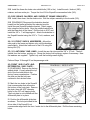
FORM #9600.01-082109 PRINTED IN U.S.A. PAGE 4 OF 12 Once unloaded, scribe an alignment mark on each bar to note its indexing in relation to the crossmember, the bars are to be reinstalled in the same position. Slide the torsion bars forward into the lower control arms (LCA) and the adjuster arms will fall free. Remove the three crossmember-to-frame bolts on each end of the crossmember. Shift the crossmember rearward and remove the bars. Now remove the crossmember from the frame rails. NOTE: Label the bars (front / rear end and driver / passenger side), they must be reinstalled on the same side and in the same front / rear direction as stock. Steps 3 through 5 are performed one side at a time. Start with the driver side. 3) SHOCK ABSORBERS, BRAKE CALIPER, AND ROTOR… Disconnect and discard the stock shocks. Unbolt the brake caliper / anchor plate assembly and tie it up and out of the way. Do not detach the brake hose from the caliper, nor the caliper form the anchor plate. Remove the brake rotor. 4) ANTI-SWAY BAR LINK AND OUTER TIE ROD END… Disconnect the anti-sway bar link from the anti-sway bar body and the LCA. Use a puller tool to separate the outer tie rod from the knuckle. 5) KNUCKLE / HUB DISASSEMBLY… Remove the three bolts that attach the disc brake rotor shield to the knuckle. If equipped with 4-wheel anti-lock brakes, remove the bolt that attaches the sensor wire to the knuckle. Now unplug the sensor wire at the connector located at the frame rail. Remove the axle hub nut. Remove the three hub bolts. Push inward on the end of the axle as you pull off the hub. The hub assembly is a slip fit onto the axle, so normally a puller tool will not be needed. Take care not to extend the CV joint and boot. Support the knuckle with a jack beneath the LCA, just inboard of the ball joint. Use a puller tool to separate the upper ball joint from the knuckle. The knuckle is now held only by the lower ball joint. Use a puller tool to free the joint then set the knuckle aside. Take care not to damage the wheel bearing seal, which is a press fit in the backside of the knuckle. If in good condition, the seal can be reused in the new Superlift knuckle. Remove the two LCA-to-frame bolts and set the LCA aside. Perform steps 3 through 5 on the passenger side. 6) DRIVESHAFT… Scribe an index mark on the driveshaft and pinion flange. Disconnect the axle end of the driveshaft and tie it up and out of the way. 7) FRONT DIFFERENTIAL / AXLE ASSEMBLY… Disconnect the axle vent and vacuum lines from the differential.