1
GE Healthcare
B30 Patient Monitor
User’s Reference Manual
B30 Patient Monitor
English
2039820-001 C (Paper)
2044678-001 C (CD)
© 2009 General Electric Company.
All Rights Reserved.
B30 patient Monitor
User's Reference Manual
Related to software license L-DICU08
Monitoring functions
0459
Conformity according to the Council Directive 93/42/EEC concerning Medical Devices.
All specifications are subject to change without notice.
Document no. 2039820-001
15th July, 2009
GE Medical Systems Information Technologies, Inc.
8200 West Tower Avenue
Milwaukee, WI USA
Zip: 53223
Tel: 1 414 355 5000 (outside US)
800 558 5102 (US only)
Fax: 1 414 355 3790
www.gehealthcare.com
Copyright © 2009 General Electric Company. All rights reserved.
GE Healthcare
3F Building 1, GE Technology Park
1 Huatuo Road
Shanghai PRC 201203
Tel: +86 21 3877 7888
Fax: +86 21 3877 7451
Intended purpose (Indications for use)
The B30 patient monitor is intended for multiparameter patient monitoring. The B30 monitor is
indicated for continuous monitoring of hemodynamic parameters (including arrhythmia and
ST segment analysis) and respiratory status and creation of limit alarms. The B30 monitor is
intended for all hospital patients and all hospital departments including intra-hospital
transport but excluding harsh physical environment like MRI.
The Patient side module E-PSM(P)W and accessories are indicated for monitoring of
hemodynamic parameters of all hospital patients. The hemodynamic parameters of the
module comprise ECG (including ST-Segment and arrhythmia), impedance respiration,
oscillometric NIBP (sys/dia/mean), temperature, SpO2 (including monitoring during conditions
of clinical patient motion), and invasive blood pressure. Impedance respiration measurement is
indicated for patients ages three years and up. The NIBP measurement is indicated for patients
who weight 5kg (11 lb) or up.The E-PSM(P)W is intended for all hospital departments including
intra-hospital transport but excluding harsh physical environment like MRI.
The extension module N-FCREC (option N-FCREC or N-FC) is indicated for monitoring of CO2 and
respiration rate of all hospital patients. CO2 measurements are indicated for patients who
weight over 5 kg (11 lb).
The B30 monitor and N-F(C)(REC) Extension Module and E-PSM(P)W Patient Side Module are
indicated for use by qualified medical personnel only.
Classifications
In accordance with IEC 60601-1
Class I and internally powered equipment – the type of protection against electric shock.
Type BF or CF equipment. The degree of protection against electric shock is indicated by a
symbol on each parameter module.
Equipment not suitable for use in the presence of a flammable anesthetic mixture with air or
with oxygen or nitrous oxide.
Continuous operation according to the mode of operation.
Portable Monitor.
In accordance with IEC 60529
IPX1 - degree of protection against harmful ingress of water.
In accordance with EU Medical Device Directive
The B30 patient monitor is classified as IIb.
In accordance with CISPR 11:
Group 1, Class B:
• Group 1 contains all ISM (Industrial, scientific and medical) equipment in which there is
intentionally generated and/or used conductively coupled radio-frequency energy which is
necessary for the internal functioning of the equipment itself.
• Class B equipment is suitable for use in domestic establishments and in establishments
directly connected to a low voltage power supply network which supplies buildings used for
domestic purposes.
Responsibility of the manufacturer
GE Medical Systems Information Technologies, Inc. is responsible for the effects on safety,
reliability and performance of the equipment only if:
• assembly, extensions, readjustments, modifications, servicing and repairs are carried out
by personnel authorized by GE.
• the electrical installation of the monitor room complies with appropriate requirements.
• the equipment is used in accordance with the "User's Guide."
Product availability
Some of the products mentioned in this manual may not be available in all countries. Please,
consult your local representative for the availability.
Trademarks
Dash, Datex, Ohmeda, S/5, D-fend, D-fend+, Mini D-fend, OxyTip+, ComWheel, ComBar, EarSat,
FingerSat, FlexSat are trademarks of GE Healthcare. All other product and company names are
property of their respective owners.
End User License Agreement
THIS DOCUMENT IS A LEGAL AGREEMENT BETWEEN YOU, THE "LICENSEE," AND GE HEALTHCARE
(“GE”). IF YOU DO NOT AGREE TO ALL THE TERMS OF THIS AGREEMENT, PROMPTLY RETURN THE
ENTIRE PACKAGE, INCLUDING ALL ACCESSORIES, IN THEIR ORIGINAL PACKAGE, WITH YOUR
SALES RECEIPT TO GE FOR A FULL REFUND.
1. Grant of License. GE grants to Licensee a nonexclusive, nontransferable, restricted license,
without right to sublicense, to use the copy of the incorporated software/firmware("Software"),
and manuals and documentation related to the Software in connection with Licensee's use of
the product for their labeled purpose and only when the instrument is used with authorized
accessories and sensors, in accordance with this End User License Agreement ("Software
License"). GE reserves all rights not expressly granted to Licensee.
2. Ownership of Software/Firmware. Title to, ownership of, and all rights and interests in, any
software and/or firmware and the documentation, and all copies thereof, remain at all times
vested in GE or its partners, and they do not pass to Licensee.
3. Assignment. The rights and obligations of the Licensee under this Software License are
personal. Accordingly, neither this Software License nor any of such rights and obligations are
assignable or transferable by merger or by operation of law or otherwise without the prior
written consent of GE. You may not rent, lease, sell, or otherwise dispose of the software/
firmware or the products on a temporary basis. GE may assign this Software License and/or
any rights of Licensor hereunder, to any affiliate, or to any purchaser of substantially all of the
assets used by GE in the performance of this Software License.
4. Limitation of liability. Other than the attached limited warranty, the Software is being
licensed to Licensee "as is," without warranty of any kind, express or implied, including without
limitation the warranties of merchantability, fitness for a particular purpose, functionality, use
or performance of the Software and compatibility with particular computer systems, computer
peripherals or other software packages, title or non-infringement. Some jurisdictions do not
allow the disclaimer of implied warranties, so the above disclaimer may not apply to Licensee,
in which case the duration of any such implied warranties is limited to the longer of (i) minimum
required by law or (ii) thirty (30) days from the date the Software is received by Licensee.
In no case, including without limitation any breach of a fundamental term or a fundamental
breach of this Software license, shall GE be liable for any damages, including but not limited to
indirect, exemplary, special, consequential or incidental damages of any kind (including
without limitation lost profits), even if GE has been advised of the possibility of such damages.
These provisions hereof shall apply to the full extent permitted by law.
5. Copy Restrictions. The software/firmware and the accompanying written materials are
copyrighted. Unauthorized copying of the software, including software that has been modified,
merged, or included with other software, or other written materials is expressly forbidden. You
may be held legally responsible for any copyright infringement that is caused or incurred by
your failure to abide by the terms of this license.
6. Use Restriction. As the Licensee, you may physically transfer the products from one location
to another provided that the software/firmware is not copied. You may not electronically
transfer the software/firmware from the products to any other device. You may not disclose,
publish, translate, release or distribute copies of the software/firmware to others. You may not
modify, adapt, translate, reverse engineer, decompile, disassemble, or create derivative works
based on the software/firmware, unless and to the extent specifically permitted by local law.
Your license to the software is not valid for use with any unauthorized data acquisition device.
When information of the internal structure of the Software is necessary in order to obtain
interoperability of the Software with other software programs, Licensee shall immediately
contact GE.
The Software contains proprietary and confidential information of GE and its suppliers and is
considered by GE and its suppliers to constitute valuable trade secrets. Licensee will hold the
Software in confidence and shall protect the Software with at least the same degree of care
with which Licensee protects its own similar confidential information but in no event less than
a reasonable standard of care. Licensee agrees that its officers and employees shall protect
the confidentiality of the Software and all confidential and non-public information relating
thereto and shall not disclose such information to any third party. This obligation of
confidentiality shall survive the termination of the Software License.
Licensee agrees to comply with all applicable export and re-export restrictions and regulations
imposed by the government of the United States or of the country to which the Software is
shipped to Licensee. Licensee shall not commit any act or omission, which will result in a
breach of any such export requirements. Licensee shall defend, indemnify and hold GE and all
GE's suppliers harmless from any claims arising out of Licensee's violation of such export
control laws.
Upon termination by GE or its suppliers of this Software License, Licensee shall (as advised by
GE) immediately destroy the Software and all copies thereof or return the same to GE and
within two (2) business days thereafter certify to GE in writing that in accordance with
instructions from GE or its suppliers, all copies of the Software have been either destroyed or
returned to GE, whether same is in tangible or intangible form and Licensee shall further certify
that all use thereof is and shall remain terminated.
7. No waiver. The failure of GE to enforce any provision of this Software License shall not be
considered a waiver of any subsequent breach of that provision or as a waiver of any other
provision hereof.
8. Amendments. This Software License may be modified only by a written instrument expressly
agreed to by the parties hereto.
Warranty
This Product is sold by GE Healthcare (“GE”) under the warranty set forth in the following
paragraphs. Such warranty is extended only with respect to the purchase of this Product
directly from GE or GE’s Authorized Dealers as new merchandise and is extended to the Buyer
thereof, other than for the purpose of resale.
For a period of twelve (12) months from the date of original delivery to Buyer, this Product,
other than expandable parts, is warranted against functional defects in materials and
workmanship and to conform to the description of the Product contained in this manual and
accompanying labels and/or inserts, provided that the same is properly operated under the
conditions of normal use, that regular periodic maintenance and service is performed and that
the replacements and repairs are made in accordance with the instructions provided, using
genuine parts and performed by a trained person. The foregoing warranty shall not apply if the
Product has been repaired by anyone other than GE or otherwise than in accordance with
written instructions provided by GE, or altered by anyone other than GE, or if the Product has
been subject to abuse, misuse, negligence, or accident.
GE’s sole and exclusive obligation and Buyer’s sole and exclusive remedy under the above
warranty is limited to repairing or replacing, free of charge, at GE’s option, a Product, which is
telephonically reported to the nearest GE office or GE’s Authorized Dealers office and which, if
so advised by GE, is thereafter returned with a statement of observed deficiency, not later than
seven (7) days after the expiration date of the applicable warranty, to the GE office or GE’s
Authorized Dealers office during normal business hours, transportation charges prepaid, and
which, upon GE’s examination, is found not to conform to the above warranty. GE shall not be
otherwise liable for any damages including but not limited to incidental damages,
consequential damages, or special damages.
There are no express or implied warranties, which extend beyond the warranty hereinabove
set forth. GE makes no warranty of merchantability or fitness for particular purpose with
respect to the product or parts thereof.
Table of contents
Table of contents
About this manual
1
Safety precautions
2
System description
3
Monitoring basic
4
Alarms
5
Monitor setup
6
Trends
7
Patient data management
8
Printing and recording
9
Cleaning and care
10 Troubleshooting
11 ECG
12 Pulse oximetry
13 Temperature
14 Invasive blood pressure
15 Impedance respiration
16 Non-invasive blood pressure
17 Airway gas (CO2)
Index
i
Table of contents
ii
Table of contents
Table of contents
About this manual
1
Intended audience . . . . . . . . . . . . . . . . . . . . . . . . . . . . . . . . . . . . . . . . . . . . . . . . . . . . . . . . . . . . . . . . . . . About-1
Overview . . . . . . . . . . . . . . . . . . . . . . . . . . . . . . . . . . . . . . . . . . . . . . . . . . . . . . . . . . . . . . . . . . . . . . . . . . . . About-1
Illustrations and names . . . . . . . . . . . . . . . . . . . . . . . . . . . . . . . . . . . . . . . . . . . . . . . . . . . . . . . . . . . About-1
Conventions used in this manual . . . . . . . . . . . . . . . . . . . . . . . . . . . . . . . . . . . . . . . . . . . . . . . . . . . . . About-2
Related documentation . . . . . . . . . . . . . . . . . . . . . . . . . . . . . . . . . . . . . . . . . . . . . . . . . . . . . . . . . . . . . . About-2
Installation and service . . . . . . . . . . . . . . . . . . . . . . . . . . . . . . . . . . . . . . . . . . . . . . . . . . . . . . . . . . . . About-3
i
Table of contents
ii
About this manual
About this manual
Intended audience
This manual is intended for clinical professionals. Clinical professionals are expected to have a
working knowledge of medical procedures, practices, and terminology, as required for
monitoring critically ill patients.
Overview
This User’s Reference Manual describes the functions offered by the B30 patient monitor
running the software license L-DICU08. As the monitor setup may vary, some menus, displays
and functions described may not be available in the monitor you are using.
This manual is an integral part of the product and describes its intended use. Keep it always
close to the equipment. Observance of the manual is a prerequisite for proper product
performance and correct operation and ensures patient and operator safety.
NOTE: Before using your monitor, please read the “User’s Guide” or this manual thoroughly.
This User’s Reference Manual gives you more specific information about the clinical and
technical aspects. Pay special attention to WARNING and CAUTION statements.
The new user of the monitor should begin with sections “Safety precautions” “System
description” and “Monitoring basic.” These sections describe the system and the basic
operation of the monitor.
The measurement sections describe the measurement technique, setup and how to adjust
displays and menus for patient monitoring and special views.
Section “Monitor setup” gives instructions about setting up the system and making changes in
the default settings. Section “Cleaning and care” describes cleaning and daily maintenance
procedures.
Illustrations and names
All illustrations in this manual are only examples, and may not necessarily reflect your system
settings or data displayed in your system. If a particular selection is not available in your
system, the selection is shown grayed in the menu.
All names used in examples and illustrations are fictitious.
1
B30 Patient Monitor
Conventions used in this manual
To help you find and interpret information easily, the manual uses consistent text formats:
Hard keys
Names of the hard keys on the Command board, side panel and
modules are written in the following way: Others.
Menu items
Software terms that identify window parts or menu items are written
in bold italic: Lab Data.
Menu access
Menu access is described from top to bottom. For example, the
selection of the Monitor Setup hard key, the Screen Setup menu
item and the Waveform Fields menu item would be shown as
Monitor Setup - Screen Setup - Waveform Fields.
File names etc.
File names, file paths and text to be entered are written in the
following way: comm.exe.
Messages
Messages (alarm messages, informative messages) displayed on the
screen are written inside single quotes: ‘Please wait.’
References
When referring to different sections in this manual or to other
manuals, manual names and section names are enclosed in double
quotes: See section "Cleaning and care." Please refer to "Technical
Reference Manual: Installation."
WARNING
CAUTION
This is a WARNING.
This is a CAUTION.
NOTE
This is a NOTE.
The following symbols are also used to distinguish procedures:
ECG
Press the menu key described.
Turn the ComWheel.
Push the ComWheel.
Related documentation
Software options and default settings are described in the “Default Configuration Worksheet”
delivered with each monitor.
Available accessories are described in the “Supplies and Accessories” catalog delivered with
each monitor.
For more information about the iCentral, see the “iCentral User’s Reference Manual”.
2
About this manual
Installation and service
A separate “Technical Reference Manual” describes installation, interfacing, connectors,
service, maintenance and reparation procedures of the monitor.
Medical electrical equipment needs special precautions regarding EMC and needs to be
installed and put into service according to the EMC information provided in the “Technical
Reference Manual” by qualified personnel.
Service and repairs are allowed for authorized service personnel only.
3
B30 Patient Monitor
4
Table of contents
Table of contents
1
Safety precautions
1-1
Warnings . . . . . . . . . . . . . . . . . . . . . . . . . . . . . . . . . . . . . . . . . . . . . . . . . . . . . . . . . . . . . . . . . . . . . . . . . . . . . . . . . 1-1
Cautions . . . . . . . . . . . . . . . . . . . . . . . . . . . . . . . . . . . . . . . . . . . . . . . . . . . . . . . . . . . . . . . . . . . . . . . . . . . . . . . . . . 1-2
ESD precautionary procedures . . . . . . . . . . . . . . . . . . . . . . . . . . . . . . . . . . . . . . . . . . . . . . . . . . . . . . . . . . . . 1-3
ESD precautionary procedure training . . . . . . . . . . . . . . . . . . . . . . . . . . . . . . . . . . . . . . . . . . . . . . . . . . 1-3
Points to note . . . . . . . . . . . . . . . . . . . . . . . . . . . . . . . . . . . . . . . . . . . . . . . . . . . . . . . . . . . . . . . . . . . . . . . . . . . . . 1-3
Disposal . . . . . . . . . . . . . . . . . . . . . . . . . . . . . . . . . . . . . . . . . . . . . . . . . . . . . . . . . . . . . . . . . . . . . . . . . . . . . . . . . . 1-3
i
Table of contents
ii
Safety precautions
1 Safety precautions
The following list contains all the general warnings and cautions you should know before
starting to use the system. Warnings and cautions specific to parts of the system can be found
in the relevant section.
Warnings
WARNING
A WARNING indicates a situation in which the user or the patient may be in
danger of injury or death.
•
•
•
•
•
To avoid explosion hazard, do not use the monitor in presence of flammable anesthetics.
•
•
•
•
•
Do not use an additional multiple socket outlet, extension cord or adapter of any kind.
•
•
•
•
•
Never install the monitor so that it is above the patient.
•
Use only approved accessories, including mounts and batteries, and defibrillator-proof
cables and invasive pressure transducers. For a list of approved supplies and accessories,
see the "Supplies and Accessories" catalog delivered with the monitor. Other cables,
transducers, batteries and accessories may cause a safety hazard, damage the
equipment or system, result in increased emissions or decreased immunity of the
equipment or system or interfere with the measurement. Protection against cardiac
defibrillator discharge is due in part to the accessories for pulse oximetry (SpO2),
temperature (T) and invasive pressure (P) measurement.
•
Single-use accessories are not designed to be re-used. Re-use may cause a risk of
contamination and affect the measurement accuracy.
•
The monitor or its components should not be used adjacent to or stacked with other
equipment. If adjacent or stacked use is necessary, the monitor and its components
should be observed to verify normal operation in configuration in which it will be used.
Connect only one patient to the monitor at a time.
Do not use the monitor without manufacturer approved mounting attached.
Use only hospital-grade grounded power outlets and power cord.
To avoid the risk of electric shock, this equipment must only be connected to a supply
mains with protective earth.
Use only an intact power cord.
Do not user the power cord for any other product or purpose.
Do not apply mechanical tension to the power cord, otherwise it may be damaged.
Some equipment malfunctions may not generate a monitor alarm. Always keep the
patient under close surveillance.
Do not use the monitor in high electromagnetic fields (for example, during MRI).
Do not connect any external devices to the system other than those specified.
Do not touch the patient, table, instruments, modules or the monitor during defibrillation.
Pins of connectors identified with the ESD warning symbol should not be touched.
Connections should not be made to these connectors unless ESD precautionary
procedures are used. For details, see ”ESD precautionary procedures” page 1-2.
1-1
B30 Patient Monitor
•
When detaching modules, be careful not to drop them. Always support with one hand
while pulling out with the other.
•
If you accidentally drop the monitor or modules, have them checked by authorized
service personnel prior to clinical use.
•
If the integrity of the external protective earth conductor arrangement is in doubt, use the
monitor with battery operation.
•
Vibrations during intrahospital transport may disturb SpO2, ECG, impedance respiration,
InvBP and NIBP measurements.
•
If the unit fails to respond as described, do not use the monitor until tested and repaired
by authorized service personnel.
•
•
The system is intended for use by qualified medical personnel only.
•
Make sure that the leadwire set clips or snaps do not touch any electrically conductive
material including earth.
When using the electrosurgery unit, ensure proper contact of the ESU return electrode to
the patient to avoid burns at monitor measurement sites.
Cautions
CAUTION
A CAUTION indicates a situation in which the unit or the devices connected to it
may be damaged.
•
Before connecting the power cord to a power supply, check that the local voltage and
frequency correspond with the rating stated on the device plate.
•
•
Leave space for air circulation to prevent the monitor from overheating.
•
Refresh the batteries completely every six months.
Do not store or use the monitor outside the temperature and humidity ranges specified in
“Performance” in section “System description” of this manual.
ESD precautionary procedures
•
To avoid electrostatic charges to build up, it is recommended to store, maintain and use
the equipment at a relative humidity of 30% or greater. Floors should be covered by ESD
dissipative carpets or similar. Non-synthetic clothing should be used when working with
the component.
•
To prevent applying a possible electrostatic discharge to the ESD sensitive parts of the
equipment, one should touch the metallic frame of the component or a large metal object
located close to the equipment. When working with the equipment and specifically when
the ESD sensitive parts of the equipment may be touched, a grounded wrist strap
intended for use with ESD sensitive equipment should be worn. Refer documentation
provided with the wrist straps for details of proper use.
ESD precautionary procedure training
• It is recommended that all potential users receive an explanation of the ESD warning
symbol and training in ESD precautionary procedures.
•
1-2
The minimum content of an ESD precautionary procedure training should include an
introduction to the physics of electrostatic charge, the voltage levels that can occur in
normal practice and the damage that can be done to electronic components if they are
touched by an operator who is electrostatically charged. Further, an explanation should
be given of methods to prevent build-up of electrostatic charge and how and why to
Safety precautions
discharge one’s body to earth or to the frame of the equipment or bond oneself by
means of a wrist strap to the equipment or the earth prior to making a connection.
Points to note
•
Medical electrical equipment needs special precautions regarding electromagnetic
compatibility, EMC, and needs to be installed and put into service according to the EMC
information provided in the "Technical Reference Manual" by qualified personnel.
•
Portable and mobile RF communications equipment can affect the medical electrical
equipment.
•
The equipment is suitable for use in the presence of electrosurgery. Please notice the
possible limitations in the parameter sections and in “Performance” on page 2-30.
•
Service and repairs are allowed for authorized service personnel only.
•
Dispose of the whole device, parts of it, its packing material and manuals in accordance
with local environmental and waste disposal regulations.
Disposal
Product Compliance
The B30 Patient Monitor is classified in the following categories for compliance:
•
•
•
•
•
•
•
•
•
•
This equipment is suitable for connection to public mains as defined in CISPR 11.
This Monitor conforms to general safety standard for medical devices to IEC 60601-1.
This Monitor conforms to EMC safety standard to IEC 60601-1-2.
This Monitor conforms to usability safety standard for medical devices to IEC 60601-1-6.
Software is developed in accordance with IEC 60601-1-4.
The application of risk management analysis to medical device conforms to ISO 14971.
The SpO2 Parameter conforms to ISO 9919.
The TEMP parameter conforms to EN 12470-4.
The CO2 parameter conforms to ISO 21647.
This Monitor conforms to particular safety standard for multifunction patient monitoring
equipment to IEC 60601-2-49 with the exception of Sub- clause 51.103; 51.103.1 and
51.102.4.
NOTE:
WARNING
−
This Monitor conforms to particular safety standard for multifunction patient
monitoring equipment to IEC 60601-2-49 with the exception of Sub- clause 51.103:
Both non-latched and latched alarms are selectable for technical alarms.
−
If the Latching Alarms selection is active, both technical alarm and physiological
alarm messages stay on the screen even if the initial alarm condition goes away.
The latching alarms function is convenient for the user to analyze and track
the old state of the patient. This is a advanced function, which protected by
the password in the monitor. This function should be operated by a
qualified medical personnel only. The latched technical alarms do not affect
safety and effectiveness of monitor.
1-3
B30 Patient Monitor
NOTE:
WARNING
−
This Monitor conforms to particular safety standard for multifunction patient
monitoring equipment to IEC 60601-2-49 with the exception of Sub- clause
51.103.1: A new technical alarm only triggers a visual indication, not the audible
alarm.
−
During silencing, all new alarms for the same reason and all alarms for a different
reason are indicated only visually.
In clinical conditions, caregivers are more likely to silence alarms when
they consider these alarms quietly cacophony and may distract and
overwhelm the clinicians. Appropriate visual textual message indicated in
B30 still work to direct the caregiver's attention to the unexpected situation
when alarms are silenced. However, the alarm silence function should be
carefully used, the clinical practitioner should check the monitor’s screen
frequently during silencing.
NOTE:
•
−
This Monitor conforms to particular safety standard for multifunction patient
monitoring equipment to IEC 60601-2-49 with the exception of Sub- clause
51.102.4: New PHYSIOLOGICAL ALARM(S) beginning after the activation of SILENCE/
RESET resume audio-visual ALARM manifestations
−
Refer to the exception of Sub- clause 51.103.1 for the same performance and
warning.
The invasive blood pressure parameter conforms to the IEC 60601-2-34 with the
exception of Sub-clause 51.300 and 51.207.4
NOTE:
−
The invasive blood pressure parameter conforms to the IEC 60601-2-34 with the
exception of Sub-clause 51.300: Both non-latched and latched alarms are
selectable for technical alarms.
−
Refer IEC 60601-2-49 item for monitor’s performance and warnings.
NOTE:
•
−
The invasive blood pressure parameter conforms to the IEC 60601-2-34 with the
exception of Sub-clause 51.207.4: A new alarm only triggers a visual indication, not
the audible alarm.
−
Refer IEC 60601-2-49 item for monitor’s performance and warnings.
The ECG parameter conforms to IEC 60601-2-27 with the exception of Sub-clause
50.102.8 a); 51.103.2; 51.103.3.4; 51.104.1 and 51.104
NOTE:
WARNING
1-4
−
The ECG parameter conforms to IEC 60601-2-27 with the exception of Sub-clause
50.102.8 a): Frequency response: The output signal amplitudes are out of range at
Method A 40HZ and Method B
−
The ECG high-frequency response limit for monitoring filter and ST filter with 50 Hz
power supply frequency is 30 Hz, but not 40 Hz according the 60601-2-27.
In clinical conditions, the high-frequency response limit of 30 Hz for
monitoring filter and ST filter with 50 Hz power supply frequency is
adequately and safe for these lethal arrhythmia identification which are
available in B30. The diagnostic filter is recommended for diagnostic
purposes.
Safety precautions
NOTE:
−
The ECG parameter conforms to IEC 60601-2-27 with the exception of Sub-clause
51.103.2: SILENCE/RESET of PHYSIOLOGICAL ALARMS/Sub-clause 51.104.1: Auditory
manifestation of TECHNICAL ALARMS: A new alarm only triggers a visual indication,
not the audible alarm.
−
Refer IEC 60601-2-49 item for monitor’s performance and warnings.
NOTE:
−
The ECG parameter conforms to IEC 60601-2-27 with the exception of Sub-clause
51.103.3.4: New PHYSIOLOGICAL ALARM(s) beginning after activation of SILENCE/
RESET resumed the auditory and visual ALARM manifestations
−
Refer IEC 60601-2-49 items for monitor’s performance and warnings.
NOTE:
•
−
The ECG parameter conforms to IEC 60601-2-27 with the exception of Sub-clause
51.104: Both non-latched and latched alarms are selectable for technical alarms.
−
Refer IEC 60601-2-49 items for monitor’s performance and warnings.
The NIBP parameter conforms to IEC 60601-2-30, EN 1060-1, EN 1060-3 with the
exception of Sub-clause 22.4.1, 51.103 of IEC 60601-2-30 and Sub-clause 5 of EN 1060-1.
NOTE:
−
WARNING
The NIBP parameter conforms to IEC 60601-2-30 with the exception of Sub- clause
22.4.1: In single fault condition, the functioning independently of the normal
pressure control system does not prevent immediately.
Prolonged use and frequent blood pressure determinations can lead to
venous pooling and congestion. Devices that exert pressure on tissue have
been associated with purpura, skin avulsion, compartmental syndrome,
ischemia, and/or neuropathy. To minimize these potential problems,
especially when monitoring at frequent intervals or over extended periods
of time, make sure the cuff is applied appropriately and examine the cuff
site and the limb distal to the cuff regularly for signs of impeded blood flow.
NOTE:
−
The NIBP parameter conforms to IEC 60601-2-30 with the exception of Sub-clause
51.103: Both non-latched and latched alarms are selectable for technical alarms.
−
Refer IEC 60601-2-49 item for monitor’s performance and warnings.
NOTE:
WARNING
−
The NIBP parameter conforms to EN1060-1 with the exception of Sub-clause 5:
Abbreviations; “Mean” used instead “M” or “MAP”.
−
The word “Mean” is used in monitor instead of “M” or “MAP” as the value for the NIBP
pressure mean average.
The clinical practitioner can understand “Mean” is the abbreviation of NIBP
pressure mean average. The B30 monitor is intended for use by qualified
medical personnel only.
•
The alarm systems of the Monitor conform to IEC 60601-1-8 with the exception of Subclause 6.3.3.1a
NOTE:
1-5
B30 Patient Monitor
−
The alarm systems of the Monitor conform to IEC 60601-1-8 with the exception of
Sub-clause 6.3.3.1a: An ALARM SYSTEM provided with auditory ALARM SIGNALS shall
have at least one set of ALARM SIGNALS.
−
The characteristics of auditory alarm signals are different from IEC 60601-1-8
requirement. This is only ms quantitative difference that can’t be defected by
human audition, according to the usability study, it has no negative effect in clinical
use.
0459
1-6
Comformity according to the Council Directive
93/42/EEC concerning Medical Devices.
Table of contents
Table of contents
2
System description
2-1
Principles of functions . . . . . . . . . . . . . . . . . . . . . . . . . . . . . . . . . . . . . . . . . . . . . . . . . . . . . . . . . . . . . . . . . . . . . 2-1
System introduction . . . . . . . . . . . . . . . . . . . . . . . . . . . . . . . . . . . . . . . . . . . . . . . . . . . . . . . . . . . . . . . . . . . . . . 2-1
Components . . . . . . . . . . . . . . . . . . . . . . . . . . . . . . . . . . . . . . . . . . . . . . . . . . . . . . . . . . . . . . . . . . . . . . . . . . . . . . 2-2
Optional components . . . . . . . . . . . . . . . . . . . . . . . . . . . . . . . . . . . . . . . . . . . . . . . . . . . . . . . . . . . . . . . . . . 2-3
Rear panel connections . . . . . . . . . . . . . . . . . . . . . . . . . . . . . . . . . . . . . . . . . . . . . . . . . . . . . . . . . . . . . . . . . . . 2-3
Module overview . . . . . . . . . . . . . . . . . . . . . . . . . . . . . . . . . . . . . . . . . . . . . . . . . . . . . . . . . . . . . . . . . . . . . . . . . . 2-4
Patient Side Module E-PSMW . . . . . . . . . . . . . . . . . . . . . . . . . . . . . . . . . . . . . . . . . . . . . . . . . . . . . . . . . . . 2-4
Patient Side Module E-PSMPW . . . . . . . . . . . . . . . . . . . . . . . . . . . . . . . . . . . . . . . . . . . . . . . . . . . . . . . . . . 2-5
Extension Module N-FC . . . . . . . . . . . . . . . . . . . . . . . . . . . . . . . . . . . . . . . . . . . . . . . . . . . . . . . . . . . . . . . . 2-6
Extension Module N-FCREC . . . . . . . . . . . . . . . . . . . . . . . . . . . . . . . . . . . . . . . . . . . . . . . . . . . . . . . . . . . . . 2-7
Extension Module N-FREC . . . . . . . . . . . . . . . . . . . . . . . . . . . . . . . . . . . . . . . . . . . . . . . . . . . . . . . . . . . . . . 2-7
General module description . . . . . . . . . . . . . . . . . . . . . . . . . . . . . . . . . . . . . . . . . . . . . . . . . . . . . . . . . . . . 2-8
Inserting and removing a module . . . . . . . . . . . . . . . . . . . . . . . . . . . . . . . . . . . . . . . . . . . . . . . . . . . . . . . 2-8
Keyboards . . . . . . . . . . . . . . . . . . . . . . . . . . . . . . . . . . . . . . . . . . . . . . . . . . . . . . . . . . . . . . . . . . . . . . . . . . . . . . .2-10
Command Board keys . . . . . . . . . . . . . . . . . . . . . . . . . . . . . . . . . . . . . . . . . . . . . . . . . . . . . . . . . . . . . . . .2-10
Side panel . . . . . . . . . . . . . . . . . . . . . . . . . . . . . . . . . . . . . . . . . . . . . . . . . . . . . . . . . . . . . . . . . . . . . . . . . . . .2-11
Batteries . . . . . . . . . . . . . . . . . . . . . . . . . . . . . . . . . . . . . . . . . . . . . . . . . . . . . . . . . . . . . . . . . . . . . . . . . . . . . . . .2-12
Battery indicators . . . . . . . . . . . . . . . . . . . . . . . . . . . . . . . . . . . . . . . . . . . . . . . . . . . . . . . . . . . . . . . . . . . . .2-13
Replacing the batteries . . . . . . . . . . . . . . . . . . . . . . . . . . . . . . . . . . . . . . . . . . . . . . . . . . . . . . . . . . . . . . . .2-14
Conditioning a battery . . . . . . . . . . . . . . . . . . . . . . . . . . . . . . . . . . . . . . . . . . . . . . . . . . . . . . . . . . . . . . . .2-15
Symbols and abbreviations . . . . . . . . . . . . . . . . . . . . . . . . . . . . . . . . . . . . . . . . . . . . . . . . . . . . . . . . . . . . . .2-15
Equipment safety symbols . . . . . . . . . . . . . . . . . . . . . . . . . . . . . . . . . . . . . . . . . . . . . . . . . . . . . . . . . . . .2-15
Other symbols . . . . . . . . . . . . . . . . . . . . . . . . . . . . . . . . . . . . . . . . . . . . . . . . . . . . . . . . . . . . . . . . . . . . . . . .2-16
Abbreviations . . . . . . . . . . . . . . . . . . . . . . . . . . . . . . . . . . . . . . . . . . . . . . . . . . . . . . . . . . . . . . . . . . . . . . . . .2-19
Performance . . . . . . . . . . . . . . . . . . . . . . . . . . . . . . . . . . . . . . . . . . . . . . . . . . . . . . . . . . . . . . . . . . . . . . . . . . . .2-30
Power supply . . . . . . . . . . . . . . . . . . . . . . . . . . . . . . . . . . . . . . . . . . . . . . . . . . . . . . . . . . . . . . . . . . . . . . . . .2-30
Battery operation . . . . . . . . . . . . . . . . . . . . . . . . . . . . . . . . . . . . . . . . . . . . . . . . . . . . . . . . . . . . . . . . . . . . .2-30
Environmental conditions . . . . . . . . . . . . . . . . . . . . . . . . . . . . . . . . . . . . . . . . . . . . . . . . . . . . . . . . . . . . .2-30
Alarm behavior . . . . . . . . . . . . . . . . . . . . . . . . . . . . . . . . . . . . . . . . . . . . . . . . . . . . . . . . . . . . . . . . . . . . . . .2-30
Defibrillator & IABP synchronization connector . . . . . . . . . . . . . . . . . . . . . . . . . . . . . . . . . . . . . . . . .2-30
Hemodynamic modules E-PSM, E-PSMP . . . . . . . . . . . . . . . . . . . . . . . . . . . . . . . . . . . . . . . . . . . . . . . .2-31
Modules with CO2 measurement, N-FC and N-FCREC . . . . . . . . . . . . . . . . . . . . . . . . . . . . . . . . . . .2-34
Modules with recorder, N-FREC and N-FCREC . . . . . . . . . . . . . . . . . . . . . . . . . . . . . . . . . . . . . . . . . . .2-35
i
Table of contents
ii
System description
2 System description
Principles of functions
The B30 monitor is a modular multiparameter patient monitor. The monitor is especially
designed for monitoring in PACU, ED, Wards, Step down units, ICU, CCU and OR in regions
where anesthesia gas monitoring is not required. It can also be used during transportation
within the hospital.
The modular design makes the system flexible and easy to upgrade.
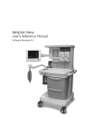
System introduction
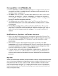
The B30 monitor system may consist of the elements shown below.
NOTE: Your system may not include all these components. Consult your local
representative for the available components.
1
2
3
Figure 2-1
B30 patient monitor system
(1)
B30 with module(s)
(2)
Printer (network printer only)
(3)
Other monitors in the network. NOTE: You cannot view other monitors on the B30 with LDICU08 software.
NOTE: The allowed cables, batteries, transducers and accessories for the monitor are
listed in the “Supplies and Accessories” catalog delivered with the monitor.
WARNING
WARNING
WARNING
If you accidentally drop the monitor, modules or frames, have them
checked by authorized service personnel prior to clinical use.
Connect only one patient to the monitor at a time.
Do not use the monitor without manufacturer approved mounting
attached.
2-1
B30 Patient Monitor
WARNING
CAUTION
Before starting to use the system, ensure that the whole combination
complies with the international standard IEC 60601-1-1 and with the
requirements of the local authorities. Do not connect any external devices
to the system other than those specified.
The monitor display is fragile. Ensure that it is not placed near a heat source or
exposed to mechanical shocks, pressure, moisture or direct sunlight.
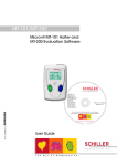
Components
The main components of the B30 are the monitor frame and the interchangeable modules.
2
1
3
4
5
12
6
11
10
Figure 2-2
(1)
9
8
7
B30 monitor front panel
Battery compartment
(2)
Transportation handle
(3)
Alarm light
(4)
Alarm LED indicators
(5)
Side panel keys
(6)
The ComWheel
(7)
Command Board keys
(8)
Guide rail for GCX mounting
(9)
Mains power and battery LEDs
(10) ON/standby key
(11) Defibrillator & IABP synchronization connector (marked with X5)
(12) Measurement modules, see page 2-4
You can use one E-PSM(P)W and/or one N-Fx module in the monitor at a time.
2-2
System description
Optional components
Optional components are:
•
•
Patient Side Modules E-PSMW and E-PSMPW
Extension Modules N-FREC, N-FCREC and N-FC
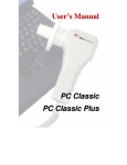
Rear panel connections
1
5
2
6
3
11
9
Figure 2-3
8
7
4
Rear panel connections
(1)
Battery compartment
(2)
Slot for infusion pole mounting
(3)
Module connector (marked with X4)
(4)
Guide rail for GCX mounting
(5)
Receptacle for power cord
(6)
Fuse holder
(7)
Serial port (marked with X9)
(8)
Network ID connector (marked with X8)
(9)
Connector for future use (marked with X7)
(10) Accessory: Multi I/O adapter (with connectors 7 - 9 above)
(11) Network connector
(12) Equipotential connector
2-3
B30 Patient Monitor
Module overview
Different modules measure different parameters. See below for module descriptions and
features.
Patient Side Module E-PSMW
1
2
6
3
4
5
Figure 2-4
2-4
Module E-PSMW
(1)
Module keys
(2)
NIBP connector
(3)
Temperature connector: 2-channel measurement
(4)
SpO2 connector
(5)
ECG (3/5 lead) and impedance respiration connector
(6)
Tab for removing the module
System description
Patient Side Module E-PSMPW
1
2
3
7
4
5
6
Figure 2-5
Module E-PSMPW
(1)
Module keys
(2)
NIBP connector
(3)
Invasive blood pressure connector: 2-channel measurement
(4)
Temperature connector: 2-channel measurement
(5)
SpO2 connector
(6)
ECG (3/5 lead) and impedance respiration connector
(7)
Tab for removing the module
Module keys
The E-PSM(P)W modules have the following direct function keys:
Auto
On/Off
For starting or stopping the NIBP
automatic cycling.
Start
Cancel
For starting or stopping the NIBP
manual cycling.
Zero P1
For zeroing pressure channel P1
NOTE: with E-PSMPW only.
Zero P2
For zeroing pressure channel P2
NOTE: with E-PSMPW only.
2-5
B30 Patient Monitor
Extension Module N-FC
2
3
4
1
5
Figure 2-6
2-6
Module N-FC
(1)
Module insertion guide for attaching an E-PSM(P)W module
(2)
Sample gas inlet
(3)
Water trap
(4)
Gas outlet
(5)
Tab for removing the module
System description
Extension Module N-FCREC
2
1
4
5
3
6
7
Figure 2-7
Module N-FCREC
(1)
Recorder
(2)
Paper compartment lever
(3)
CO2 measurement
(4)
Water trap
(5)
Tab for removing the module
(6)
Sample gas inlet
(7)
Gas outlet
Extension Module N-FREC
2
1
3
Figure 2-8
Module N-FREC
(1)
Recorder
(2)
Paper compartment lever
(3)
Tab for removing the module
2-7
B30 Patient Monitor
General module description
The modules are plugged into the monitor. They can be removed or inserted during monitoring.
Inserting and removing a module
Figure 2-9
Inserting and removing a module
To insert a module:
1.
Align the module with the insertion guide. E-PSM(P)W and N-Fx modules are all inserted
the same way.
2.
Push the module into the monitor frame until it clicks.
To remove a module:
Pull the module out using the tab.
WARNING
2-8
When detaching modules, be careful not to drop them. Always support with
one hand while pulling out with the other.
System description
Using two modules
1
2
Figure 2-10 Using two modules
NOTE: You can use one E-PSM(P)W and/or one N-Fx module in the monitor at a time.
To install an E-PSM(P)W and an N-Fx module:
1.
Insert the N-Fx module first, see ”Inserting and removing a module” page 2-8.
2.
Attach the E-PSM(P)W to the N-Fx.
2-9
B30 Patient Monitor
Keyboards
You can control monitoring through the keys on the Command Board and side panel, module.
For more information, see section ”Monitoring basic.”
Command Board keys
1
2
10
3
4
Admit/
Discharge
Pt.Data
& Trends
Monitor
Setup
Print/
Record
9
8
6
5
ECG
NIBP
Invasive
Pressures
Airway
Gas
Others
Normal
Screen
7
Figure 2-11 Command Board keys and LED indicators
(1)
ON/standby key
(2)
Mains power ON (lit) or OFF (dark): indicates mains or external DC power
(3)
For admitting or discharging a patient; for selecting user modes
(4)
For viewing trends and alarm history
(5)
For activating parameter specific menus. NOTE: All modules do not measure all of these
parameters. For more information, see “Module overview” on page 2-4.
(6)
For returning the Normal Screen view to the screen
(7)
For activating pulse oximetry, impedance respiration and temperature setup menus
(8)
For printing and recording different trends and waveforms
(9)
For setting up the monitor and for activating the HELP menu
(10) Battery operation LEDs, see “Batteries” on page 2-12.
2-10
System description
Side panel
Alarm LED indicators, see section ”Alarms.”
Silence
Alarms
Alarms
Setup
For silencing the alarms.
For activating the Alarms Setup menu.
Invasive Pressures
Zero
ALL
For zeroing the invasive pressure channels.
NOTE: Functional with the E-PSMPW module only.
NIBP
For starting the NIBP autocycling.
Start
Cancel
For starting or stopping the NIBP manual cycling.
Recorder
For starting or stopping local recording.
NOTE: Functional with N-FREC and N-FCREC modules only.
2-11
B30 Patient Monitor
Batteries
The monitor can be run either on mains power or batteries. Battery operation is initiated when
the power cord is disconnected or when the mains power is lost during monitoring.
NOTE: Always use the B30 with batteries inserted. Otherwise all trend data and
temporary settings are lost if the power cable is detached from the mains.
NOTE: Before using the monitor for the first time, charge the batteries to their full
capacity. Charging time is two hours per battery pack.
The B30 has two lithium-ion batteries at most, located in the battery compartment. They can
be charged separately, and screen symbols and monitor frame LEDs indicate their charging
level and possible failure, see below. You can also check the battery status through Monitor
Setup - Battery Setup. The internal battery capacity is up to 4.5 hours with fully charged
batteries.
Monitor
Setup
NOTE: When the monitor is battery powered, the green battery LED is on. When the
monitor is mains powered, the green mains LED is on.
If you wish to have the battery charge visible at all times, select it in one of the digit fields:
Monitor Setup - Screen Setup - Digit Fields - Battery. You can now see how much charging
time is left for each battery separately both in numbers and as symbols, and the total charging
time in numbers.
WARNING
2-12
Use only manufacturer approved batteries. Contact GE service if you need
to order new batteries.
System description
Battery indicators
The B30 messages, screen symbols and front panel LED indicators tell the user about the
status of the batteries. For screen symbols, see page 2-15. For LED indicators, consult the table
below and for messages, see section “Troubleshooting.”
Table 2-1
Battery indicators
Screen symbol
A
B
B
B
A
B
B
Explanation
Front panel battery
LED indicators
Monitor is battery
powered. Batteries are
fully charged; the size of
the green bar indicates
the charging level.
green lit
Monitor is battery
powered. Battery A is
empty, battery B charge
is ok.
green lit
Monitor is battery
powered. Battery A
failure, battery B is full.
green lit
orange dark
orange dark
orange flashing
NOTE: If both batteries fail, the green battery LED is dark.
B
no screen symbol
Monitor is mains
powered. Battery A is
being charged (white
bar), battery B is already
charged.
green dark
Monitor is mains
powered. 'No battery
backup' message on
screen. Batteries have
failed or they are not
inserted.
green dark
orange lit
orange flashing
2-13
B30 Patient Monitor
Checking the battery charge when the monitor is turned off
When the monitor is turned off, you can
check the battery charging level by
pressing the test button on the battery
as indicated in the drawing on the left.
The charging indicator bar (1) lights up
and the number of lit segments
indicates the charging level: the more lit
segments, the higher the charging level.
1
Figure 2-12 Charging indicator on the battery
Replacing the batteries
Check the monitor indicators regularly to see if either one of the batteries needs to be changed.
Battery capacity indicators in the upper right corner tell you when you should replace a
battery, and which one is out of charge, missing or not working. You can replace one battery at
a time.
To replace a battery:
A
B
1
2
3
Figure 2-13 Inserting a battery
CAUTION
2-14
(1)
Open the lid of the battery compartment located behind the handle by sliding it to the
left.
(2)
Lift up the battery you want to change. Check the indicators and messages on screen to
make sure that you change the battery with lower charge.
(3)
Push in the new battery. Make sure that the charging indicator is facing forward and push
the battery down all the way. Check the monitor indicators.
After replacing a battery, always make sure to close the battery compartment
by sliding the lid back to the right until it clicks.
System description
WARNING
Do not incinerate a battery or store at high temperatures as it will explode.
Conditioning a battery
Batteries should be conditioned regularly to maintain their useful life. Condition a battery every
six months, when its run time becomes noticeably shorter, or when the message ‘Condition
Battery x’ appears on the screen. Conditioning a battery is best done on an external charger.
Please, refer to instructions provided with the charger.
If you do not have an external charger, see section “Cleaning and care”:“Conditioning a
battery”.
Symbols and abbreviations
Equipment safety symbols
-
Attention, consult accompanying documents.
-
On the modules or frames indicates that modules with identical
measurements should not be used in the same monitor. If such modules
have been inserted, remove the module that has been most recently
connected. You can also remove both modules and re-connect the new
module after five seconds.
-
On the E-PSM(P)W module indicates that protection against cardiac
defibrillator discharge is due in part to the accessories for pulse oximetry
(SpO2), temperature (T) and invasive pressure (P) measurement.
-
On the N-FC(REC) module indicates that airway gases should be calibrated
every six months in normal use and every two months in continuous use.
-
On top of the monitor beside the battery cover: Use manufacturer
recommended batteries only. Follow the regional regulations for disposal.
-
On the rear panel this symbol indicates the following warnings and
cautions:
* Electric shock hazard. Do not open the cover or the back. Refer servicing
to qualified service personnel.
* For continued protection against fire hazard, replace the fuse only with
one of the same type and rating.
* Disconnect from the power supply before servicing.
* Do not touch the monitor during defibrillation.
* Do not use the monitor without manufacturer approved mounting
attached.
* Lithium battery on the CPU board: follow the regional regulations for
disposal.
* Use manufacturer recommended batteries only.
Type BF (IEC 60601-1) protection against electrical shock.
Type BF (IEC 60601-1) defibrillator-proof protection against electric shock.
Type CF (IEC 60601-1) protection against electric shock.
2-15
B30 Patient Monitor
Type CF (IEC 60601-1) defibrillator-proof protection against electric shock.
When displayed in the upper left corner of the screen, indicates that the
alarms are silenced. When displayed in the menu or digit fields, indicates that
the alarm source has been turned off or alarm does not meet the alarmspecific activation criteria.
ESD warning symbol for electrostatic sensitive devices. Pins of connectors
identified with the ESD warning symbol should not be touched. Connections
should not be made to these connectors unless ESD precautionary procedures
are used. For details, see ”ESD precautionary procedures” page 1-2.
Symbol for non-ionizing electromagnetic radiation. Interference may occur in
the vicinity of equipment marked with this symbol.
Other symbols
Equipotentiality. Monitor can be connected to potential equalization
conductor.
Alternating current
Fuse. Replace the fuse only with one of the same type and rating.
SN
Serial Number
In the front panel: battery.
A
B
B
B
B
Battery operation and remaining capacity. The height of the green bar
indicates the charging level.
Battery (A) charging (white bar)
Battery (A) failure
Both batteries have failed
2-16
System description
B
Battery (A) is missing
In the front panel: mains or external DC power
Submenu. Selecting an alternative marked with this symbol in a menu opens
a new menu.
The monitor is connected to Network
A blinking heart next to the heart rate or pulse rate value indicates the beats
detected.
A lung next to the respiration rate value indicates that respiration rate is
calculated from the impedance respiration measurement.
Gas inlet
Gas outlet
Do not reuse.
Use by. Indicates the last use day.
Date of manufacture
Do not immerse the sensor in liquids.
2-17
B30 Patient Monitor
This symbol indicates that the waste of electrical and electronic equipment
must not be disposed as unsorted municipal waste and must be collected
separately. Please contact an authorized representative of the manufacturer
for information concerning the decommissioning of your equipment.
The separate collection symbol is affixed to a battery, or its packaging, to
advise you that the battery must be recycled or disposed of in accordance
with local or country laws. To minimize potential effects on the environment
and human health, it is important that all marked batteries that you remove
from the product are properly recycled or disposed. For information on how
the battery may be safely removed from the device, please consult the
service manual or equipment instructions. Information on the potential
effects on the environment and human health of the substances used in
batteries is available at this url: http://www.gehealthcare.com/euen/
weeerecycling/index.html
This product consists of devices that may contain mercury, which must be
recycled or disposed of in accordance with local, state, or country laws.
(Within this system, the backlight lamps in the monitor display contain
mercury.)
Degree of protection against harmful ingress of water as detailed in the
IEC 60529:
IPX class
IPX0
IPX1
IPX2
IPX3
IPX4
IPX7
IPX8
2-18
- Ordinary equipment
- Protection against vertically falling water drops.
- Protection against vertically falling water drops when enclosure tilted up to
15°.
- Protected against spraying water.
- Protected against splashing water.
- Protected against the effects of temporary immersion in water.
- Protected against the effects of continuous immersion in water.
System description
Abbreviations
/min
beats per minute, breaths per minute
°C
Celsius degree
°F
Fahrenheit degree
µg
microgram
A
arm (describing location)
A
alveolar
a
arterial
a/AO2
arterio-alveolar PO2 ratio
AaDO2
alveolo-arterial oxygen difference
AA
anesthetic agent
AAMI
Association for the Advancement of Medical Instrumentation
ABG
arterial blood gases
ABP
arterial pressure
ADU
Anesthesia Delivery Unit
AEP
auditory evoked potential
AirW
airway temperature
Alpha, Al
alpha frequency band
AM
Anesthesia Monitor
Amp
amplitude
Ant
anterior
APN
apnea
Arrh.
arrhythmia
Art
arterial pressure
ASY
asystole
ATMP
atmospheric pressure
ATPD
atmospheric/ambient temperature and pressure, dry gas
ATPS
ambient temperature and pressure, saturated gas
AV
atrioventricular
aVF
left foot augmented lead
avg
average
aVL
left arm augmented lead
aVR
right arm augmented lead
aw
airway
Axil
axillatory temperature
BAEP
brainstem auditory evoked potential
Bal
balance gas
bar
1 atmosphere
Beta, Be
beta frequency band
Bigem.
bigeminy
BIS
bispectral index
Blad
bladder temperature
Blood
blood temperature (C.O. measurement)
2-19
B30 Patient Monitor
2-20
Body
body temperature
BP
blood pressure
Brady
bradycardia
BSA
body surface area
BSR
burst suppression ratio
B-to-B
beat-to-beat
BTPS
body temperature and pressure, saturated gas
c
calculated/derived value
C
chest
C(a-v)O2
arteriovenous oxygen content difference
C.C.O.
continuous cardiac output
CFI
cardiac function index
C.I.
cardiac index
C.O.
cardiac output
cal.
calibration
Calc
calculated/derived value
Calcs
calculations
CAM
Compact Anesthesia Monitor
CaO2
arterial oxygen content
Casc.
cascaded (ECG)
cc
cubic centimeter
CCCM
Compact Critical Care Monitor
CCM
Critical Care Monitor
CcO2
capillary oxygen content
CCU
cardiac (coronary) care unit
CEL
Celsius degree
CFI
cardiac function index
CISPR
International Special Committee on Radio Interference
cmH2O
centimeter of water
CMRR
common mode rejection ratio
CO
carbon monoxide
CO2
carbon dioxide
COHb
carboxyhemoglobin
Compl
compliance
Cont.
continuous
Contrl
controlled ventilation
Core
core temperature
Count
count of responses
CPB
cardiopulmonary bypass
CPP
cerebral perfusion pressure
CSA
compressed spectral array
CT
computer tomography
CvO2
(mixed) venous oxygen content
System description
CVP
central venous pressure
d
day
dB
decibel
DBS
double burst stimulation (NMT)
DEL
delete
Delta, De
delta frequency band
depr.
depression
Des
desflurane
Dia
diastolic pressure
Diagn
diagnostic (ECG filter)
DIFF
difference
DIS
S/5 Device Interfacing Solution
DO2
oxygen delivery
DO2I
oxygen delivery index
DSC
digital signal converter
dyn
dynamic
e
estimated
ECG
electrocardiogram
ECG1
first ECG waveform (top)
ECG1/r
real-time ECG
ECG2
second ECG waveform
ECG3
third ECG waveform
ED
emergency department
EDV
end-diastolic volume
EDVI
end-diastolic volume index
EE
energy expenditure (kcal/24h)
EEG
electroencephalogram
EEG1
first EEG waveform
EEG2
second EEG waveform
EEG3
third EEG waveform
EEG4
fourth EEG waveform
EEMG
evoked electromyogram
EEtot
total energy expenditure
elect
electrode
elev.
elevation
EMC
electromagnetic compatibility
EMG
electromyogram
Enf
enflurane
Entr
entropy
EP
evoked potential
ESD
electrostatic discharge
Eso
esophageal temperature
2-21
B30 Patient Monitor
2-22
ESV
end-systolic volume
ESVI
end-systolic volume index
ET, Et
end-tidal concentration
EtAA
end-tidal anesthetic agent
EtBal
end-tidal balance gas
EtCO2
end-tidal carbon dioxide
EtN2O
end-tidal nitrous oxide
EtO2
end-tidal oxygen
ET-tube, ETT
endotracheal tube
EVLW
extravascular lung water
EVLWI
extravascular lung water index
Exp
expiratory
F
foot (describing location)
FAH
Fahrenheit degree
FEMG
frontal electromyogram
FFT
fast Fourier transform
FI, Fi
fraction of inspired gas
FiAA
fraction of inspired anesthetic agent
Fib
fibrillation
FiBal
fraction of inspired balance gas
FiCO2
fraction of inspired carbon dioxide
FiN2
fraction of inspired N2
FiN2O
fraction of inspired nitrous oxide
FiO2
fraction of inspired oxygen
Flow
airway gas flow
Freq.
frequent
ft
foot, feet
FVloop
flow volume loop
G
Gauss
g
gram
GEDI
global enddiastolic volume index
GEDV
global enddiastolic volume
GEF
global ejection fraction
Graph.
graphical
h
hour
H
hand (describing location)
Hal
halothane
Hb
hemoglobin
Hbtot
total hemoglobin
HCO3-
bicarbonate
Hemo
hemodynamic
System description
Hemo Calcs
hemodynamic calculations
HHb
reduced hemoglobin
HME
heat and moisture exchanger
HMEF
heat and moisture exchanger with filter
hPa
hectopascal
HR
heart rate
HRdiff
heart rate difference
ht
height
HW
hardware
Hz
hertz
IEC
International Electrotechnical Comission
I:E
inspiratory-expiratory ratio
IABP
intra-aortic balloon pump
IC
inspiratory capacity
ICP
intracranial pressure
ICU
intensive care unit
ID
identification
Imped.
impedance; impedance respiration
in
inch
Inf
inferior
Infl.
inflation (limit)
Insp
inspiratory
Inv.
invasive
Inv. BP
invasive blood pressure
Irreg.
irregular
Iso
isoflurane
ISO
International Standards Organisation
ISM
Industrial, Scientific and Medical
ITBV
intrathoracic blood volume
IVR
idioventricular rhythm
J
joule
K
kelvin
kcal
kilocalorie
kJ
kilojoule
kPa
kilopascal
L
leg (describing location)
L
left (describing location)
L, l
liter
l/min
liters/minute
Lab
laboratory
LAN
local area network
LAP
left atrial pressure
2-23
B30 Patient Monitor
2-24
Lat
lateral
lb
pound
LCD
liquid crystal display
LCW
left cardiac work
LED
light emitting diode
LVEDP
left ventricular end diastolic pressure
LVEDV
left ventricular end diastolic volume
LVSW
left ventricular stroke work
LVSWI
left ventricular stroke work index
MAC
minimum alveolar concentration
Max
maximum
mbar
millibar
mcg
microgram
Mean
mean blood pressure
mEq
milliequivalent
MetHb
methemoglobin
MF
median frequency
mg
milligram
min
minute
Min
minimum
ml
milliliter
MLAEP
middle-latency auditory evoked potential
mmHg
millimeters of mercury
mol
mole
Monit
monitoring (ECG filter)
MRI
magnetic resonance imaging
Mult.
multiple
Multif. PVCs
multifocal PVCs
MV
minute volume
MVexp
expired minute volume (l/min)
MVexp(BTPS)
expired minute volume in BTPS conditions
MVexp(STPD)
expired minute volume in STPD conditions
MVinsp
inspired minute volume (l/min)
MVspont
spontaneous minute volume
Myo
myocardiac temperature
N
neutral
N2
nitrogen
N2O
nitrous oxide
Na
sodium
Naso
nasopharyngeal temperature
neo
neonate
Net
network
System description
NIBP
non-invasive blood pressure
Ni-Cd
nickel-cadmium
Ni-MH
nickel-metal hydride
NMT
neuromuscular transmission
NO
nitric oxide
NTPD
normal temperature and pressure, dry gas
Num.
numerical
O2
oxygen
O2ER
oxygen extraction ratio
O2Hb
oxygenated hemoglobin
OR
operation room
Oxy
oxygenation
Oxy Calcs
oxygenation calculations
P
partial pressure
P
pressure
P(BTPS)
pressure in BTPS conditions
P(g-a)CO2
difference between gastrointestinal carbon dioxide and arterial blood
carbon dioxide concentration
P(g-ET)CO2
difference between gastrointestinal carbon dioxide and end tidal
carbon dioxide concentration
P(STPD)
pressure in STPD conditions
P1, P2
invasive pressure channel identification on module
PA
pulmonary artery
Pa
Pascal (unit of pressure)
Paced
paced beats
PaCO2
partial pressure of carbon dioxide in the arteries
PAO2
partial pressure of oxygen in the alveoli
PaO2
partial pressure of oxygen in the arteries
PAOP
pulmonary artery occlusion pressure
PA
pulmonary arterial pressure
Paw
airway pressure
Pbaro
barometric pressure
PCWP
pulmonary capillary wedge pressure
PE
polyethylene
pedi
pediatric
PEEP
positive end-expiratory pressure
PEEPe
extrinsic positive end expiratory pressure
PEEPe+i
total positive end expiratory pressure (ICU)
PEEPe+PEEPi
total positive end expiratory pressure (ICU)
PEEPi
intrinsic positive end expiratory pressure
PEEPtot
total positive end expiratory pressure (anesthesia)
PgCO2
gastrointestinal carbon dioxide concentration
2-25
B30 Patient Monitor
2-26
pH
pH
pHa
arterial pH
pHi
intramucosal pH
pHv
(mixed) venous pH
PIC
patient interface cable
Pleth
plethysmographic pulse waveform
PM
pacemaker
PM non-capt.
pacemaker non-capturing
PM non-funct.
pacemaker non-functioning
Pmax
maximum pressure
Pmean
mean pressure
Pmin
minimum pressure
Ppeak
peak pressure
Pplat
plateau (pause) pressure
PR
pulse rate
Prev.
previous
psi
pounds per square per inch
pt
patient
PTC
post tetanic count (NMT)
pts
patients
PVC
polyvinylchloride
PVC
premature ventricular contraction
PVloop
pressure volume loop
PvO2
partial pressure of oxygen in (mixed) venous blood
PVR
pulmonary vascular resistance
PVRI
pulmonary vascular resistance index
Px
standard pressure label, x being 1, 2, 3, 4, 5, or 6
QRS
QRS complex
Qs/Qt
venous admixture
R
right (describing location)
RAP
right atrial pressure
Raw
airway resistance
RCW
right cardiac work
RCWI
right cardiac work index
RE
Response Entropy
Rect
rectal temperature
REF
right ventricular ejection fraction
ref.
reference
Resp
respiration rate (total) (set)
Resp Rate
respiration rate (total) (measured)
RF
radio frequency
RMS
average (root mean square) power
System description
Room
room temperature
RQ
respiratory quotient
RR
respiration rate (total) (measured)
rtm
rhythm
RV
residual volume
RVEDV
right ventricular end-diastolic volume
RVESV
right ventricular end-systolic volume
RVP
right ventricular pressure
RVSW
right ventricular stroke work
RVSWI
right ventricular stroke work index
s
second
SA
sinoatrial
SaO2
arterial oxygen saturation
S.A.R.
specific absorption rate
SD
standard deviation
SE
State Entropy
SEF
spectral edge frequency
SEMG
spontaneous electromyogram
Sev
sevoflurane
SI
stroke index
Skin
skin temperature
SN, S/N
serial number
Spiro
patient spirometry
SpO2
oxygen saturation
Spont
spontaneous breathing
SQI
signal quality index
SR
suppression ratio
SR
sinus rhythm
SSEP
somatosensory evoked potentials
ST
single twitch (NMT)
ST
ST segment of electrocardiograph
stat
static
STAT
continuous NIBP cuff inflation for five minutes
STBY
standby
Stfilt
ST filter (ECG)
STPD
standard temperature and pressure, dry gas
Surf
surface temperature
SV
stroke volume
SVC
supraventricular contraction
SVI
stroke volume index
SvO2
(mixed) venous oxygen saturation
SVR
systemic vascular resistance
SVRI
systemic vascular resistance index
2-27
B30 Patient Monitor
2-28
SW
software
SVV
stroke volume variation
Sys
systolic pressure
t
time (min)
T
temperature
T
tesla
T(BTPS)
temperature in BTPS conditions
T1%
first stimulus as % of the reference value (NMT)
T1, T2
temperature channel identification on module
Tab.
tabular
Tachy
tachycardia
Tbl, Tblood
blood temperature
Tcorr
temperature correction
Temp
temperature
Theta, Th
theta frequency band
Tinj
injectate temperature
TOF
train of four (NMT)
TOF%
ratio of the 4th to the 1st response (NMT)
Trigem.
trigeminy
TV
tidal volume
TVexp
expired tidal volume (ml)
TVinsp
inspired tidal volume (ml)
Tx
temperature label, x being 1, 2, 3, or 4 or one of the other label choices
Tymp
tympanic temperature
v
venous
V
ventricular
V
volume
V/Q
ventilation/perfusion ratio
V0.5
volume expired during the first 0.5 seconds
V1.0
volume expired during the first second
VA
alveolar ventilation
VC
vital capacity
VCO2
carbon dioxide production
Vd
dead space
Vd/Vt
dead space ventilation
Vent Calcs
ventilation calculations
VFib
ventricular fibrillation
VO2
oxygen consumption
VO2Calc
calculated oxygen consumption*
VO2CalcI
calculated oxygen consumption index*
VO2I
oxygen consumption index
Vol
volume
System description
V Run
ventricular run
V Tachy
ventricular tachycardia
WLAN
wireless local area network
wt
weight
X
extreme
yr
year
yrs
years
* with Fick equation
2-29
B30 Patient Monitor
Performance
WARNING
Operation of the monitor outside the specified values may cause inaccurate
results.
Any fluctuations within the specified limits do not affect the performance.
NOTE: Information in this section can be especially useful to clinicians.
Power supply
Rated voltages and frequencies:
Allowed voltage fluctuations:
Maximum power consumption:
100 to 240 V 50/60 Hz
±10 %
150 VA
Battery operation
Batteries:
Charging time:
Operation time:
Exchangeable lithium-ion, 2 pcs max.
2 hours per battery pack
up to 4.5 hours
Environmental conditions
Operating temperature:
normal operation:
while charging batteries:
Storage and transport temperature:
Relative humidity:
Atmospheric pressure:
+5 to +40°C (41 to 104°F)
+5 to +35°C (41 to 95°F)
-20 to +60°C (-4 to 140°F)
10 to 90 % noncondensing
670 to 1060 mbar (500 to 800 mmHg)
Alarm behavior
The maximum alarm delay of the alarm at the monitor signal output to network: 5 seconds
If the alarm mode is latched, the technical alarms are latched as well. This does not comply with the NIBP
(IEC 60601-2-30) and invasive pressure (IEC 60601-2-34) standard requirements.
Silencing alarms for 5 minutes does not comply with the SpO2 (ISO 9919) standard requirements.
Defibrillator & IABP synchronization connector
Analog output
ECG:
From first user lead (ECG1)
Gain:
1 V/mV ±10%
Delay:
< 15 ms
DC offset:
±100 mV max.
Frequency response:
0.05 Hz to 40 Hz
Invasive blood pressure:
From pressure labeled ‘Art’
Gain:
10 mV/mmHg ±2%
Delay:
< 35 ms
DC offset:
±20 mV max.
Frequency response:
DC to 30 Hz
The pacemaker pulses have been replaced with 2 ms ±20% fixed digital pulses at the ECG analog output.
A device that fulfils the requirements of the IEC 60601-1 standard can be connected to the defibrillator &
IABP synchronization connector. There are no other limitations, because the signals of the connector are
galvanically isolated from patient applied part of the ECG and invasive blood pressure measurements.
2-30
System description
Synchronization pulse
Pulse width:
Delay:
Amplitude:
Output impedance:
Current limit:
10 ms positive pulse
< 35 ms (R-wave peak to leading edge of pulse)
CMOS compatible
3.5 V min. at 1 mA sourcing
0.5 V max. at 5 mA sinking
50 ohm
10 mA
Hemodynamic modules E-PSM, E-PSMP
ECG 1
Filter modes:
With 50 Hz power supply frequency:
monitoring filter:
0.5 to 30 Hz
ST filter:
0.05 to 30Hz
diagnostic filter:
0.05 to 150 Hz
With 60 Hz power supply frequency:
monitoring filter:
0.5 to 40 Hz
ST filter:
0.05 to 40 Hz
diagnostic filter
0.05 to 150 Hz
QRS minimum detection level:
Minimum level 0.5 mV with duration between 40 and 120 ms.
Defibrillation protection:
5000 V, 360 J
Recovery time:
<5 s
Heart rate:
Measurement range:
30 to 250 bpm
Measurement accuracy:
±5 % or ±5 bpm
Displays average of 10-second median values2
Display update time:
1s
Maximum response time of heart rate meter to change in heart rate:
Response time 80 to 120 bpm:
6.9 s
Response time 80 to 40bpm:
8.2 s
Maximum Tall T wave amplitude that does not disturb the heart rate calculation time: >1.4 mV
Input impendance: >2.5 Mohm
The heart rate calculation operates with irregular rhythms of IEC 60601-2-27 6.8.2 bb 4, the heart rate
after a 20 second stablization period as follows:
Figure 101 A1): 80 bpm
Figure 101 A2): 59 bpm
Figure 101 A3): 122 bpm
Figure 101 A4): 117 bpm
Pacemaker pulse detection:
detection level:
2 to 700 mV
pulse duration:
0.5 to 2 ms
Pacemaker detector may not operate correctly during the use of high-frequency (HF) surgical equipment.
The disturbances of HF surgical equipment typically cause false positive pacer detection.
Direct current for leads-off detection
through an active patient electrode:
<30 nA
1
2
The isolation barrier capacitance in the module has been minimized to reduce the hazard of burns in the event of a
defect in the ESU return electrode connection.
When the heart rate (HR) changes rapidly, the averaging is restarted.
2-31
B30 Patient Monitor
Direct current for leads-off detection
through a reference electrode:
<120 nA
The normalized respiration sensing current between RA (R) and LL (F)
or RA (R) and LA (L) or LA (L) and LL (L):
<5.0 µA
Frequency of respiration sensing current:
31.25 kHz
Minimizing the effects of the line isolation monitor transients:
Crystal controlled oscillator used as the operating frequency source of the patient isolation power
supply.
The average time and time range ( ) to alarm (VFib or VTachy) for tachycardia waveform
are as follows (IEC60601-2-27 6.8.2.bb.6):
Figure 101 B1 halved amplitude:
9.9 s (8.4 to 11.5 s)
Figure 101 B1 normal amplitude:
7.1 s (5.8 to 8.2 s)
Figure 101 B1 doubled amplitude:
4.4 s (4.2 to 4.6 s)
Figure 101 B2 halved amplitude:
7.0 s (6.1 to 7.5 s)
Figure 101 B2 normal amplitude:
5.8 s (4.5 to 7.4 s)
Figure 101 B2 doubled amplitude:
6.1 s (5.1 to 7.0 s)
A clinician should always confirm the rhythm from the ECG waveform.
Direct cardiac application
The display area reserved for the ECG measurement in the screen may not be adequate for displaying
the complete ECG amplitude when measuring ECG direct from the surface of the heart. Clipping of the
signal can be reduced by adjusting the size of the signal on the screen (for example, from the default 1.0
to 0.2) in the ECG menu.
Impedance respiration
Respiration range:
4 to 120 resp/min
Accuracy:
± 5% or ± 5 resp/min, whichever is greater
The conducted RF immunity of the respiration measurement has been tested with 1 Vrms. The radiated
RF immunity of the respiration measurement has been tested with 1 V/m. The impedance respiration
measurement technology has been optimized so that the measurement is not sensitive to electrosurgery
equipment which is commonly used in the intended environment for the impedance respiration
measurement.
NOTE: Impedance respiration measurement is intended for patients ages three years
and up.
Invasive blood pressure1 (E-PSMP module only)
Measurement range:
Measurement accuracy:
Pulse rate:
Measurement range:
Accuracy:
Transducer sensitivity:
1
-40 to 320 mmHg (-5.3 to 42.6 kPa)
±5 % or ±2 mmHg
30 to 250 bpm
±5 % or ±5 bpm
5 µV/V/mmHg
The isolation barrier capacitance in the module has been minimized to reduce the hazard of burns in the event of a
defect in the ESU return electrode connection.
2-32
System description
Temperature1
Measurement range:
Measurement accuracy:
Probe type:
10 to 45 °C (50 to 113 °F)
±0.1 °C (25 to 45 °C)
Use only GE Healthcare temperature probes or defibrillator-proof
YSI 400 series probes.
Temperature self-check:
At start-up and then every 10 minutes.
Time constant of temperature probes:
Reusable skin temperature probe:
3s
Reusable adult central temperature probe:
6s
Reusable pediatric central temperature probe:
4s
Disposable skin temperature probe:
3 to 6 s
Disposable central temperature probe, 12F:
5 to 8 s
Disposable central temperature probe, 9F:
5 to 8 s
NIBP
Measurement range:
adult 25 to 260 mmHg (3.3 to 34.7 kPa)
child 25 to 190 mmHg (3.3 to 25.3 kPa)
infant 15 to 140 mmHg (2.0 to 18.7 kPa)
Typical measuring time:
adult less than 30 s, infant less than 25 s
Overall system accuracy:
Meets or exceeds SP10-2002 AAMI standards2
The ESU does not cause a burn hazard through the NIBP cuff, because there is no electrical connection
between the cuff and the NIBP measuring electronics.
NOTE: NIBP measurement is intended for patients who weigh 5 kg (11 lb) and up.
NOTE: The cuff pressure measurement range is equal to cuff nominal and cuff
indication ranges.
Pulse oximetry
SpO21
Automatic scaling of plethysmographic waveform.
Measurement and display range:
0 to 100 %
Calibration range:
70 to 100 %
Calibrated against functional oxygen saturation.
Measurement accuracy 3 :
100 to 70 %, ±2 digits
69 to 0 %, unspecified
Display resolution:
1 digit (1% of SpO2)
Wavelength of SpO2 probe LEDs:
Infrared LED
940 nm
Red LED
660 nm
Maximum energy of SpO2 probe LEDs:
Infrared LED
Red LED
Pulse rate:
Measurement and display range:
4
Measurement accuracy :
1
2
3
42 µJ/pulse
62 µJ/pulse
30 to 250 bpm
±5 % or ±5 bpm, whichever is greater
The isolation barrier capacitance in the module has been minimized to reduce the hazard of burns in the event of a
defect in the ESU return electrode connection.
According to SP10-2002 AAMI 4.4.5.2.B, Intra-arterial method as the reference standard, mean difference of the test
system and the comparison system shall be ± 5 mmHg or less with standard deviation of 8 mmHg or less
Accuracy is based on deep hypoxia studies with volunteered subjects during motion and non-motion conditions over a
wide range of arterial blood oxygen saturations as compared to arterial blood CO-Oximetry. Accuracy may depend on
the sensor used, please refer to the instructions for use in the accessory package. The accuracy is expressed as rms. This
means that approximately two-thirds of the data will fall within the accuracy range.
2-33
B30 Patient Monitor
Default alarm limits 1:
SpO2 high Off, low 90%
PR high 160, low 40
NOTE: For each SpO2 accessory, refer to the instructions for use in the accessory
package for patient weight limits and accuracy.
Modules with CO2 measurement, N-FC and N-FCREC
Sampling rate:
Maximum sampling line length:
Sampling delay:
Total system response time:
150 ±25 ml/min (sampling line 2 to 3 m, normal conditions)
6m
2.1 s typical with a 3-m sampling line
2.4 seconds typical with a 3-m sampling line, including sampling
delay and rise time (typically 3.7 seconds with a 6-m sampling
line)
Warm-up time:
1 min for operation, 30 min for full specification
Autozeroing interval:
4, 15, 30 and 60 minutes after start-up, then every 60 minutes
Automatic compensation for barometric pressure.
Gas values are measured in ATPD conditions (ambient temperature and pressure, dry). When CO2 is
displayed as a partial pressure (kPa, mmHg), the value can be alternatively shown as wet (BTPS, body
temperature and pressure saturated).
Non-disturbing gases are those with a maximum effect on the CO2 reading at 5.0 vol% < 0.2 vol%. The
effect is valid for specific concentrations shown in parentheses of the non-disturbing gas:
Ethanol C2H5OH (<0.3%)
Acetone (<0.1%)
Methane CH4(<0.2%)
Nitrogen N2(0 to 100%)
water vapor (0 to 100%)
Dichlorofluoromethane (<1%)
Tetrafluoroethane (<1%)
Disturbing gases and their effect on the CO2 reading at 5.0 vol-% CO2 are shown below. Errors listed
reflect the effect of specific concentrations (shown in parentheses) of an individual disturbing gas and
should be combined when estimating the effect of gas mixtures:
Halothane (4%) increases < 0.3 vol%
Isoflurane(5%) increases < 0.4 vol%
Enflurane(5%) increases < 0.4 vol%
Desflurane(24%) increases < 1.2 vol%
Sevoflurane(6%) increases < 0.4 vol%
Helium (50%) decreases < 0.3 vol%
O2 (40 to 95%) decreases < 0.3 vol%
If O2 compensation is not activated:
If O2 compensation is activated:
O2 (40 to 95%) error < 0.15 vol%
If N2O compensation is not activated: N2O (40%) decreases < 0.4 vol%
If N2O compensation is activated:
4
1
N2O (40 to 80%) error < 0.3 vol%
The reported SpO2 pulse rate accuracy is the product specification. SpO2 pulse rate accuracy tests with a simulator
yielded a PR error of less than 2 bpm (rms) over the whole measurement range.
Limits are adjustable:
OFF to 51% for SpO2 high
50 to 100% for SpO2 low
250 to 35 bpm for PR high
30 to 245 bpm for PR low
2-34
System description
Default alarm limits 1:
EtCO2 high 8%, low 3%
FiCO2 high 3%, low Off
Carbon dioxide (CO2)
Measurement range:
0 to 20 vol %
Resolution:
0.01%
Measurement rise time:
< 300 ms with nominal flow
Accuracy:
0 to 15 vol%
± (0.2 vol % + 2% of reading)
15 to 20 vol%
± (0.7 vol % + 2% of reading)
Valid for respiration rate < 40 1/min at I:E ratio of 1:1. (Relative error is typically 10% for respiration rate 80
1/min at I:E ratio of 1:1.) The accuracy is specified in simulated ventilation. With higher respiration rates
and with varying ventilation methods the specifications may not be met.
Respiration rate
Breath detection:
1% change in CO2 level
Measurement range:
Accuracy:
4 to 80 breaths/min
±1 breath/min in the range 4 to 20 breath/min,
±5% in the range 20 to 80 breath/min
1 breath/min
Resolution:
NOTE: CO2 measurement is intended for patients who weigh over 5 kg (11 lb).
Modules with recorder, N-FREC and N-FCREC
Power consumption
Recorder type:
Print resolution:
Paper width:
Traces:
Print speed:
1
3W
Thermal array
vertical 8 dots/mm
horizontal 24 dots/mm
50 mm, printing width 48 mm
Selectable 1, 2 or 3 waveforms
1, 6.25, 12.5, 25 mm/s
Alarm limits and their adjustment range may vary depending on the mode used.
2-35
B30 Patient Monitor
2-36
Table of contents
Table of contents
3
Monitoring basics
3-1
Principles . . . . . . . . . . . . . . . . . . . . . . . . . . . . . . . . . . . . . . . . . . . . . . . . . . . . . . . . . . . . . . . . . . . . . . . . . . . . . . . . . 3-1
Modules and module keys . . . . . . . . . . . . . . . . . . . . . . . . . . . . . . . . . . . . . . . . . . . . . . . . . . . . . . . . . . . . . . 3-1
Patient Side Module, E-PSM . . . . . . . . . . . . . . . . . . . . . . . . . . . . . . . . . . . . . . . . . . . . . . . . . . . . . . . . . . . . . 3-1
Patient Side Module, E-PSMPW . . . . . . . . . . . . . . . . . . . . . . . . . . . . . . . . . . . . . . . . . . . . . . . . . . . . . . . . . 3-2
Module with built-in recorder, N-FREC . . . . . . . . . . . . . . . . . . . . . . . . . . . . . . . . . . . . . . . . . . . . . . . . . . . 3-2
Module with CO2 measurement and built-in recorder, N-FCREC . . . . . . . . . . . . . . . . . . . . . . . . . . . 3-3
Module with CO2 measurement, N-FC . . . . . . . . . . . . . . . . . . . . . . . . . . . . . . . . . . . . . . . . . . . . . . . . . . . 3-4
Command Board . . . . . . . . . . . . . . . . . . . . . . . . . . . . . . . . . . . . . . . . . . . . . . . . . . . . . . . . . . . . . . . . . . . . . . . . . 3-4
Command Board keys . . . . . . . . . . . . . . . . . . . . . . . . . . . . . . . . . . . . . . . . . . . . . . . . . . . . . . . . . . . . . . . . . 3-5
Side panel keys . . . . . . . . . . . . . . . . . . . . . . . . . . . . . . . . . . . . . . . . . . . . . . . . . . . . . . . . . . . . . . . . . . . . . . . . . . . 3-6
Using menus . . . . . . . . . . . . . . . . . . . . . . . . . . . . . . . . . . . . . . . . . . . . . . . . . . . . . . . . . . . . . . . . . . . . . . . . . . . . . 3-7
Starting and ending . . . . . . . . . . . . . . . . . . . . . . . . . . . . . . . . . . . . . . . . . . . . . . . . . . . . . . . . . . . . . . . . . . . . . .3-10
Preparations . . . . . . . . . . . . . . . . . . . . . . . . . . . . . . . . . . . . . . . . . . . . . . . . . . . . . . . . . . . . . . . . . . . . . . . . . .3-10
Starting monitoring . . . . . . . . . . . . . . . . . . . . . . . . . . . . . . . . . . . . . . . . . . . . . . . . . . . . . . . . . . . . . . . . . . .3-10
Entering and loading patient data . . . . . . . . . . . . . . . . . . . . . . . . . . . . . . . . . . . . . . . . . . . . . . . . . . . . .3-11
During monitoring . . . . . . . . . . . . . . . . . . . . . . . . . . . . . . . . . . . . . . . . . . . . . . . . . . . . . . . . . . . . . . . . . . . .3-11
Automatic discharge of the patient . . . . . . . . . . . . . . . . . . . . . . . . . . . . . . . . . . . . . . . . . . . . . . . . . . . .3-11
Ending monitoring . . . . . . . . . . . . . . . . . . . . . . . . . . . . . . . . . . . . . . . . . . . . . . . . . . . . . . . . . . . . . . . . . . . .3-11
i
Table of contents
ii
Monitoring basic
3 Monitoring basic
Principles
You can control monitoring of the B30 patient monitor through the keys on the Command
Board, side panel and modules.
Module keys and side panel keys control a set of the most often used functions while the
Command Board keys give access to all functions.
Modules and module Keys
The module keys start or end a function immediately. They are designed to make the most
common monitoring tasks easier and quicker to use.
The accessories have to be plugged to the respective module before module keys become
operative.
Refer to “System description” on page 2-1 for detail modules and keyboards instructions.
3-1
B30 Patient Monitor
Using menus
A menu is a list of functions or commands displayed on the monitor screen.
To display a menu, press one of the Command Board keys.
Figure 3-1
3-2
Example of a menu
(1)
Menu header
(2)
List of menu selections
(3)
Indicates the present selection
(4)
Adjustment window with other options
(5)
Short instructions
(6)
Entry indicator to submenus
Monitoring basic
Select items in the menus with the ComWheel. For example, to change what is displayed in the
ECG display:
Select the desired
function by pressing
the menu key.
ECG
Turn the ComWheel
to move the highlight
down in the menu to
the desired selection.
3-3
B30 Patient Monitor
Push the ComWheel to
enter an adjustment
window or a submenu
Turn the ComWheel to
choose the desired
option or selection in
the window.
Push the ComWheel to
confirm the selection.
Press the Normal Screen key to return to normal monitoring display.
Submenus are indicated by a symbol
contain less frequently used functions.
3-4
. They function just like the main menus and
Monitoring basic
Starting and ending
WARNING
WARNING
WARNING
WARNING
Always make sure that necessary alarm limits are active and set according
to the patient's clinical condition when you start monitoring a patient.
After transferring or reinstalling the monitor, always check that it is
properly connected and all parts are securely attached. Pay special
attention to this in case of stacked mounting.
Do not use the monitor without manufacturer approved mounting
attached.
If you accidentally drop the monitor or modules, have them checked by
authorized service personnel prior to clinical use.
Preparations
1.
Check that the monitor, accessories and monitor parts are clean and intact.
2.
Plug in the desired measurement modules.
3.
Turn on the monitor from the ON/standby key. The monitor performs a self-test to ensure
correct functioning.
4.
If necessary, change the user mode:
−
Press the Admit/Discharge key and select Select Mode.
The mode defines what is displayed on screen and in the trends. Note that changing the mode
also changes settings such as alarm limits.
The monitor automatically reconfigures the display when modules are inserted.
Reconfiguration of the display may take up to 5 seconds.
Starting monitoring
1.
Prepare the patient connections according to the setup picture in the measurement
section.
Use only approved supplies and accessories, see the “Supplies and Accessories” catalog.
The alarms and parameter default settings become active.
2.
Check that you have the desired waveforms and digits in the fields. If necessary, adjust
the selections:
−
Press the Monitor Setup key.
−
Select Screen Setup.
−
Select Waveform Fields or Digit Fields.
3.
Zero invasive blood pressure lines.
4.
Check the alarm limits.
−
Press the Alarms Setup side panel key.
The alarms are operative and the parameter default settings are active when the patient
is connected to the monitor.
5.
Start the measurement according to the instructions in the measurement section.
For example, zero the invasive pressure channels by pressing the Zero Px module keys,
and start NIBP measurement to get reference values.
6.
Enter or load patient data, see next page.
3-5
B30 Patient Monitor
Entering and loading patient data
Press the Admit/Discharge key and do one of the following:
−
To continue with a patient already admitted on the same monitor, select Contin.
Previous.
−
To admit a new patient, select Admit Patient.
The patient admission also happens automatically when the monitor receives vital signs.
Always observe the monitor and the patient carefully during start-up periods and when
inserting modules.
During monitoring
•
•
If you need to avoid audible alarms, press the Silence Alarms key.
Empty the water trap container of the N-FCREC or N-FC module whenever it is more than
half full.
Automatic discharge of the patient
The monitor will discharge a patient automatically after 24 hours when vital signs for some
parameters (ECG, Art, NIBP, SpO2, Resp and CO2 (with N-FCREC and N-FC only)) are not
available. When this happens, all trend data will be cleared and alarm limits will be set to
default values.
Ending monitoring
1.
Print necessary data.
−
2.
Press the Print/Record key.
Wait until the printing is finished. Then clear patient data and return settings, including
alarm limits, to their defaults by discharging the patient:
−
Press the Admit/Discharge key.
−
Select Discharge and Yes.
3.
Turn off the monitor from the ON/standby key if the monitor will not be used.
4.
Clean the monitor according to the instructions, see section ”Cleaning and care.”
Using modes
The B30 monitor has six user modes. These user modes are predefined combinations of
settings. They determine, for example, what is displayed on the screen and in trends and what
the alarm limits are. In other words, by choosing a specific mode you get suitable settings on
the screen without having to choose all features one by one.
Modes can be hospital specific. The monitor starts in start-up modes, which is one of the user
modes chosen during configuration. The default modes are STEP-DOWN, ED, PACU, CCU,
NEURO and PEDIATRIC. Please refer to the “Default Configuration Worksheet“ delivered with
the monitor for more information.
For more information about the installation settings and using modes, see section ”Monitor
setup.”
Setup monitor before use
For more information about the how to setup monitor, see section ”Monitor setup.”
3-6
Table of contents
Table of contents
4
Alarms
4-1
Overview . . . . . . . . . . . . . . . . . . . . . . . . . . . . . . . . . . . . . . . . . . . . . . . . . . . . . . . . . . . . . . . . . . . . . . . . . . . . . . . . . 4-1
Points to note . . . . . . . . . . . . . . . . . . . . . . . . . . . . . . . . . . . . . . . . . . . . . . . . . . . . . . . . . . . . . . . . . . . . . . . . . . . . . 4-2
Alarm indications . . . . . . . . . . . . . . . . . . . . . . . . . . . . . . . . . . . . . . . . . . . . . . . . . . . . . . . . . . . . . . . . . . . . . . 4-2
Alarm categories . . . . . . . . . . . . . . . . . . . . . . . . . . . . . . . . . . . . . . . . . . . . . . . . . . . . . . . . . . . . . . . . . . . . . . . . . 4-3
Alarm LED indicators . . . . . . . . . . . . . . . . . . . . . . . . . . . . . . . . . . . . . . . . . . . . . . . . . . . . . . . . . . . . . . . . . . . 4-4
Alarm light . . . . . . . . . . . . . . . . . . . . . . . . . . . . . . . . . . . . . . . . . . . . . . . . . . . . . . . . . . . . . . . . . . . . . . . . . . . . . 4-4
Alarm activation . . . . . . . . . . . . . . . . . . . . . . . . . . . . . . . . . . . . . . . . . . . . . . . . . . . . . . . . . . . . . . . . . . . . . . . . . . 4-4
Alarms Setup menu . . . . . . . . . . . . . . . . . . . . . . . . . . . . . . . . . . . . . . . . . . . . . . . . . . . . . . . . . . . . . . . . . . . . . . . 4-5
Adjusting alarm limits . . . . . . . . . . . . . . . . . . . . . . . . . . . . . . . . . . . . . . . . . . . . . . . . . . . . . . . . . . . . . . . . . . . . . 4-7
Adjusting limits . . . . . . . . . . . . . . . . . . . . . . . . . . . . . . . . . . . . . . . . . . . . . . . . . . . . . . . . . . . . . . . . . . . . . . . . 4-7
Choosing automatic limits . . . . . . . . . . . . . . . . . . . . . . . . . . . . . . . . . . . . . . . . . . . . . . . . . . . . . . . . . . . . . . 4-7
Returning to default limits . . . . . . . . . . . . . . . . . . . . . . . . . . . . . . . . . . . . . . . . . . . . . . . . . . . . . . . . . . . . . . 4-7
Changing alarm sources . . . . . . . . . . . . . . . . . . . . . . . . . . . . . . . . . . . . . . . . . . . . . . . . . . . . . . . . . . . . . . . . . . 4-8
Silencing alarms . . . . . . . . . . . . . . . . . . . . . . . . . . . . . . . . . . . . . . . . . . . . . . . . . . . . . . . . . . . . . . . . . . . . . . . . . . 4-9
Silencing audible alarms temporarily . . . . . . . . . . . . . . . . . . . . . . . . . . . . . . . . . . . . . . . . . . . . . . . . . . . 4-9
Reactivating alarms . . . . . . . . . . . . . . . . . . . . . . . . . . . . . . . . . . . . . . . . . . . . . . . . . . . . . . . . . . . . . . . . . . . . 4-9
Silencing audible alarms permanently . . . . . . . . . . . . . . . . . . . . . . . . . . . . . . . . . . . . . . . . . . . . . . . . . . 4-9
Reactivating alarms . . . . . . . . . . . . . . . . . . . . . . . . . . . . . . . . . . . . . . . . . . . . . . . . . . . . . . . . . . . . . . . . . . .4-10
Deactivating alarms . . . . . . . . . . . . . . . . . . . . . . . . . . . . . . . . . . . . . . . . . . . . . . . . . . . . . . . . . . . . . . . . . .4-11
Automatic recording on alarms . . . . . . . . . . . . . . . . . . . . . . . . . . . . . . . . . . . . . . . . . . . . . . . . . . . . . . . .4-11
Showing alarm history . . . . . . . . . . . . . . . . . . . . . . . . . . . . . . . . . . . . . . . . . . . . . . . . . . . . . . . . . . . . . . . . . . .4-12
Other adjustable features . . . . . . . . . . . . . . . . . . . . . . . . . . . . . . . . . . . . . . . . . . . . . . . . . . . . . . . . . . . . . . . .4-13
Displaying limits . . . . . . . . . . . . . . . . . . . . . . . . . . . . . . . . . . . . . . . . . . . . . . . . . . . . . . . . . . . . . . . . . . . . . .4-13
Enabling or disabling alarm silencing . . . . . . . . . . . . . . . . . . . . . . . . . . . . . . . . . . . . . . . . . . . . . . . . . .4-14
Disabling the alarm light . . . . . . . . . . . . . . . . . . . . . . . . . . . . . . . . . . . . . . . . . . . . . . . . . . . . . . . . . . . . . .4-14
Latching alarms . . . . . . . . . . . . . . . . . . . . . . . . . . . . . . . . . . . . . . . . . . . . . . . . . . . . . . . . . . . . . . . . . . . . . .4-15
Reminder volume . . . . . . . . . . . . . . . . . . . . . . . . . . . . . . . . . . . . . . . . . . . . . . . . . . . . . . . . . . . . . . . . . . . . .4-16
Changing the tone pattern . . . . . . . . . . . . . . . . . . . . . . . . . . . . . . . . . . . . . . . . . . . . . . . . . . . . . . . . . . . .4-16
i
Table of contents
ii
Alarms
4 Alarms
Overview
When an alarm for the monitored parameter becomes active:
1
2
3
Figure 4-1
View of alarms
(1)
Alarm messages appear in the message field in the order of priority.
(2)
The measurement value flashes. The color (red, yellow) indicates the alarm category (high
priority, medium priority). If the alarm is a low priority (white) note, the measurement
value is not flashing.
(3)
In some cases a message in the digit or waveform field gives more detailed information
using the color of the parameter.
An audible alarm is also triggered, and the alarm LEDs on the monitor side panel indicate the
alarm level. If enabled, also the alarm light flashes red (high priority) or yellow (medium priority)
according to alarm levels. Refer to “Default Configuration Worksheet“ for more information
about priorities and escalating.
4-1
B30 Patient Monitor
Points to note
WARNING
WARNING
When the alarms are silenced, observe the patient frequently.
Always make sure that the audio alarm volume level is adequate in your
care environment.
Alarm indications
4-2
•
When the monitor is turned on, you will hear a beep: this tells you that the alarm audio
signal is working. Also the alarm LED indicators are lit up for a few seconds. To check
them, see section ”Functioning of the alarms.” You can also check the functioning of the
audio signal and alarm light through Alarms Setup - Alarm Volume or Alarm Light.
•
If alarms are turned off and a power interruption occurs when there is no battery backup,
or if the monitor is turned off for up to 15 minutes, check the alarm status before you start
monitoring again.
•
If the monitor is connected to the network, the alarms can be heard and seen on the
Central as well. Please, consult the "iCentral User's Reference Manual: Alarms" for details.
•
If the monitor is connected to the network, the alarms can also be silenced using the
Central if this feature has been enabled in Central configuration.
Alarms
Alarm categories
The alarms are classified into three categories according to the priority: HIGH PRIORITY/RED
ALARM, MEDIUM PRIORITY/YELLOW ALARM, and LOW PRIORITY/WHITE NOTE (white color).
NOTE: Asystole and ventricular fibrillation alarms are always high priority alarms.
The priority of an alarm depends primarily on the cause and the duration (generally minimum
20 seconds) of the alarm condition, the priority increasing with the duration and according to
the physiological significance. Thus, for example, brady advances rapidly to high priority,
whereas apnea is allowed a slightly longer duration.
The monitor has three options for alarm tones and patterns: ISO, ISO2, and General. The ISO2
and ISO patterns are very similar. The difference is the rising sound of the tone pattern. The
following frame colors and tones identify the alarm categories:
Table 4-1
ISO pattern
Visual
Tone pattern
Red
For life threatening red LED
Rising triple + double
situations. High
flashing
beep every 5 seconds
(except the second tone priority alarm.
pattern which is
produced 1 second
after the first one)
-- 5 -- 5 --
Yellow
Triple beep every 19
seconds
-- 19 -- 19 --
For serious but not
life threatening
problems. Medium
priority alarm.
White
Single beep
-
yellow LED lit
Advisory note. It
may be equipment
related like ‘Leads
off’. Low priority
alarm.
Table 4-2
Meaning
Side panel
LEDs
yellow LED
flashing
Alarm light
(if enable)
flashing red
flashing
yellow
lit
yellow
ISO2 pattern
Visual
Tone pattern
Red
Rising triple + double beep every 5 For life threatening situations. High priority
seconds (except the second tone alarm.
pattern which is produced 1
second after the first one)
5
Yellow
5
Triple beep every 19.5 seconds
19,5
White
Meaning
Single beep
-
19,5
For serious but not life threatening problems.
Medium priority alarm.
Advisory note. It may be equipment related
like ‘Leads off’. Low priority alarm.
4-3
B30 Patient Monitor
Table 4-3
General pattern
Visual
Tone pattern
Meaning
Red
Continuous beep
For life threatening situations. High priority
alarm.
Yellow
Double beep every 5 seconds
For serious but not life threatening problems.
Medium priority alarm.
-- 5 -- 5 -White
Single beep
-
Advisory note. It may be equipment related
like ‘Leads off’. Low priority alarm.
There is also a sound for catastrophic situations: you hear continuous beep if the FiO2 is less
than 18%, or Ppeak is high.
Alarm LED indicators
The B30 has several alarm indicators. There are two LEDs, red and yellow, in the side panel
beside the Silence Alarms key. For their functioning, see page 4-3. These indicators can be
disabled.
Alarm light
In addition to the audible and LED indications, the B30 has an alarm light, located in the upper
right corner of the monitor frame. The alarm light can be enabled (default) or disabled, see
“Other adjustable features” on page 4-13. When enabled, it flashes red (high priority) or yellow
(medium priority) according to the currently active highest priority alarm. You can adjust the
brightness of the light in the range 5 to 100 %. To adjust the brightness of the light:
1.
Press the Alarms Setup key.
2.
Select Alarm Light and adjust with the ComWheel. During adjustment the red light is on
to help you determine a suitable brightness level.
Alarm activation
To enable the alarms, connect patient cables. If the alarm source is selected, the alarms are
active also when the measurement is not displayed (except the impedance respiration alarms).
When an alarm becomes active, messages appear in order of priority. See default settings
presented in the "Default Configuration Worksheet."
Individual alarms have their own specific requirements before they become active, for
example:
4-4
−
Apnea requires five breaths to be activated.
−
Invasive pressures need to be within alarm limits for 20 seconds after zeroing.
Alarms
Alarms Setup menu
You can view and adjust patient alarm limits in the Alarms Setup menu.
Alarms
Setup
Adjust Limits
(1)
List of selections
(2)
Exit from the alarm limit adjustment area back to Alarms Setup menu
(3)
Parameter box with high and low limit values and a 10-minute trend showing the current
status
Adjusts individual measurement alarm limits. You can also access the adjustment menu
through each parameter menu.
NOTE: If the monitor is connected to the network, the alarm limits can also be changed
using the Central if this feature has been enabled in its configuration.
Auto Limits
Auto limits are calculated from the displayed patient reading at the time when auto limits are
selected.
Default Limits Sets the alarms to the default alarm limits.
NOTE: Default limits can be changed and saved to modes. For more information, see the
"Default Configuration Worksheet."
Cancel Changes Returns all the limits to the ones set before entering the Alarms Setup menu if you have not
exited the menu yet.
Arrh. Alarms
Opens a menu to select and adjust Severe arrhythmia analysis. Alarm priorities can be
configured in this menu.
Adjust = defines the alarm priorities (red, yellow, white, off).
NOTE: You can only set the priority for V Tachy.
NOTE: V Tachy alarm cannot be selected OFF.
NOTE: Alarm priorities can also be set using the Central, depending on its
configuration.
To redisplay the Alarms Setup menu, select Alarms Setup.
For more information on arrhythmia alarms, please see section ”ECG.”
4-5
B30 Patient Monitor
Alarm Volume Adjusts the volume of the audio alarms. The range is from 1 (soft) to 10 (loud).
NOTE: Audible alarms cannot be totally silenced with the Alarm Volume function.
Alarm Light
Adjusts the brightness of the alarm light if the light has been enabled (default) through
Monitor Setup - Install/Service - Installation - Alarm Options - Alarm Light- YES. The range
is from 5 to 100%. The light is on during the adjustment to help determine a suitable brightness.
Audio ON/OFF Opens a menu to select Silence Apnea, Silence ECG, Silence Apn & ECG or Silence All.
NOTE: The silencing selections that is, all other selections than the Activate Alarms) are
available only if alarm silencing has been enabled by selecting Monitor Setup - Install/
Service - Installation - Alarm Options - Show Audio ON/OFF - Yes. By default, it is disabled. For
more details, see ”Enabling or disabling alarm silencing” page 4-14.
Activate Alarms = Activates silenced alarms. This selection is always available for activating
alarms that have been permanently silenced using the Central.
Silence Apn = Silences apnea and disconnection alarms as well as CO2, respiration rate.
Silence ECG = Silences arrhythmia alarms and also HR limit alarms.
Silence Apn & ECG = Silences both of above.
Silence ALL = Silences permanently all alarms except FiO2<18%, Ppeak >70 cmH2O.
Remove Menu
4-6
Clears the menu selections from the display so that only 10 minute trends and limits are
displayed (push the ComWheel to return the selections on the screen).
Alarms
Adjusting alarm limits
Adjusting limits
1.
Press the Alarms Setup side panel key.
2.
Select Adjust Limits.
3.
Turn the ComWheel to highlight the measurement. If the desired measurement is not
displayed in the window, select Next Page.
4.
Push the ComWheel to open an adjustment window.
5.
Turn the ComWheel to change the limits and accept them by pushing it. Move between
selections by turning the ComWheel.
6.
To return to the Alarms Setup menu to select more measurements, push the ComWheel
until the cursor is in the adjustment menu, then select Previous Menu or Alarms Setup.
7.
Press the Normal Screen key to return to normal monitoring view.
You can enter the alarm limit adjustment window also through the measurement menus.
When you are in an XX parameter menu, select XX Alarm or enter XX Setup and then select
XX Alarm.
NOTES:
•
•
ST high/low alarms will reach the white (low priority) level only.
•
If the monitor is connected to the network, the alarm limits can also be adjusted using the
Central if this feature has been enabled in its configuration. If alarm limits are adjusted
using the Central, the message 'Alarm settings changed from Central' is displayed in the
bedside monitor.
In NIBP measurement, the alarm limits change automatically according to the cuff hose
type used.
Choosing automatic limits
To activate automatic patient-specific alarm limits enabling close patient control, select Auto
Limits in the Alarms Setup menu. Limits are then calculated from the displayed patient reading
at the point of time when auto limits are selected.
Returning to default limits
Select Default Limits to set the alarms to the default alarm limits. The factory default alarm
limits are listed in the "Default Configuration Worksheet."
4-7
B30 Patient Monitor
Changing alarm sources
For NIBP, P1 and P2 (with E-PSMPW), you can select which measured values trigger the alarm.
One or several alarm sources may be active at a time.
Parameters
Alarm triggered off by
Blood pressure
(NIBP, P1, P2)
Systolic, diastolic and/or mean pressure or off
(with off, there is no 10 minute trend on
display)
1.
Press the Alarms Setup side panel key.
2.
Select Adjust Limits.
3.
Select the measurement. If the desired measurement is not displayed, select Next Page.
4.
Push the ComWheel. An adjustment window is displayed.
5.
In the adjustment window, turn the ComWheel to get from the limit setting to the menu
selections.
6.
Select X Alarm and push the ComWheel to change the selection OFF or ON.
Alarms
Setup
4-8
Alarms
Silencing alarms
Silencing audible alarms temporarily
NOTES:
•
The bedside alarms can also be silenced and acknowledged from the Central if this
feature has been enabled in the Central configuration. In this case, the message 'Alarms
silenced from Central' or 'Alarms acknowledged from Central' is displayed on the bedside
monitor display.
•
If the monitor is connected to the network and the network connection is lost, the
silenced alarms are reactivated and the volume level is automatically set to 7.
Pressing the Silence Alarms key once
• To silence all alarms for two minutes, press the Silence Alarms side panel key once.
• To silence all alarms for five minutes, keep the Silence Alarms key pressed for more
than five seconds.
NOTE: NOTE: FiO2<18%, high Ppeak alarms are always silenced only for 20 seconds.
Pressing the Silence Alarms key once silences the alarms that are currently active, and
presilences the upcoming alarms of other measurements. If the alarms are not active when
you press the Silence Alarms key, they are pre-silenced for 2 or 5 minutes.
The crossed bell symbol with a countdown timer is displayed in the upper left hand corner of
the screen to indicate that the alarms are silenced, and the message field is cleared of all the
previous alarm and note messages. The visual alarms in the digit and waveform fields remain
as long as they are valid. During silencing, all new alarms for the same reason and all alarms
for a different reason are indicated visually. Apnea alarms are activated after five breaths.
Pressing the Silence Alarms key twice
• To silence an individual alarm that is currently active, press the Silence Alarms key
twice. This does not pre-silence the upcoming alarms.
The message ‘Alarms acknowledged’ is displayed to indicate that the alarms that were
silenced by pressing the Silence Alarms key twice remain silent, whereas other upcoming
alarms will have an audible sound.
Reactivating alarms
You can reactivate the alarm sounds of new upcoming alarms by pressing the Silence
Alarms key once again during the silencing period. The alarms that were active when the key
was first pressed will not sound before the original silencing period is over.
Silencing audible alarms permanently
Silencing certain audible alarms entirely may be desirable for special cases.
4-9
B30 Patient Monitor
NOTES:
•
The following silencing selections (that is, all other selections than Activate Alarms are
available only if alarm silencing has been enabled (Monitor Setup - Install/Service Installation - Alarm Options - Show Audio ON/OFF - Yes). By default, it is disabled. You
need a password to enter the Install/Service menu. (For details, see ”Changing alarm
options” page 5-4.)
•
If the monitor is connected to the network, the bedside alarms can also be silenced using
the Central if this feature has been enabled in its configuration.
Alarms
Setup
Select one of the following:
•
•
•
•
Silence Apnea = Silences apnea and disconnection alarms as well as CO2, respiration rate,
low Ppeak, PEEP, and minute volume limit alarms permanently.
Silence ECG = Silences arrhythmia alarms and also HR limit alarms.
Silence Apn & ECG = Silences both of the above.
Silence ALL = Silences permanently all alarms except FiO2<18%, Ppeak >70 cmH2O.
Selecting a choice displays a warning symbol, for example
.
If an active alarm is silenced, the monitor gives a reminder beep every two minutes. You can
adjust the volume of the reminder beep through Monitor Setup - Install/Service Installation - Alarm Options - Reminder Volume (a password is required for this operation).
For more information, see ”Reminder volume” page 4-16.
Reactivating alarms
•
4-10
Select Alarms Setup - Audio ON/OFF - Activate Alarms to turn on audible alarms.
Alarms
Deactivating alarms
You can set the alarm limits temporarily to OFF for the following parameters: HR, SpO2 and
respiration rate. This way, you can silence a parameter without having to adjust the alarm
limits.
1.
Press the Alarms Setup key.
2.
Select Adjust Limits.
3.
Turn the ComWheel to highlight the measurement.
4.
and push the ComWheel to change the selection Off.
The symbol
appears in the digit field.
When you select the alarm limit ON again, the previous alarm limits will be active.
Automatic recording on alarms
An automatic local recording is possible when Asystole, Tachy/Brady, Art High/Low, V Fib or V
Tachy alarms reach the red alarm level. When the red alarm level is reached, the recorder
prints the ECG + Art waveforms.
1.
Press the Print/Record key.
2.
Select Record Waveforms.
3.
Select Start on Alarms and Yes.
Print/
Record
4-11
B30 Patient Monitor
Recording time is 30 seconds consisting of 12 seconds recording from the recorder memory
and 18 seconds real-time recording. The alarm source is always marked to the alarm
recordings. The following alarms start the recording:
Alarm
Recorded parameters
Asystole
ECG1 + Art waveforms, 25 mm/s
Tachy/Brady
ECG1 + Art waveforms, 25 mm/s
Art High/Low
ECG1 + Art waveforms, 25 mm/s
V Fib
ECG1 + Art waveforms, 25 mm/s
V Tachy
ECG1 + Art waveforms, 25 mm/s
V Run >3
ECG1 + Art waveforms, 25 mm/s
Alarming level
Alarms which start the recording
Severe
Asystole, Tachy/Brady, Art High/Low, V Fib, V Tachy
Showing alarm history
•
4-12
Press the Pt. Data & Trends key and select Alarm History. This displays a list of the
last 20 alarms that have reached the yellow or the red alarm level. The time and type of
occurrence are displayed next to the alarm list items.
Alarms
Other adjustable features
NOTE: This section describes the rest of the adjustable features regarding the alarms. You can
adjust each feature if you know the required password for entering the Install/Service menu. If
you wish to adjust the settings, we recommend that you contact the person responsible for the
entire configuration.
Displaying limits
You may select the alarm limits to be displayed next to the numerical parameter value.
1.
Press the Monitor Setup key.
2.
Select Install/Service and enter the password.
3.
Select Installation - Alarm Options.
4.
Select Show Limits and YES or NO.
Monitor
Setup
The alarm limits become visible when patient monitoring begins and the monitor receives
patient data.
4-13
B30 Patient Monitor
Enabling or disabling alarm silencing
With this selection, you can determine whether the audible alarms can be turned off or not.
1.
Press the Monitor Setup key.
2.
Select Install/Service and enter the password.
3.
Select Installation - Alarm Options.
4.
Select Show Audio ON/OFF and YES to enable alarm silencing or NO to disable it.
Monitor
Setup
Disabling the alarm light
By default, the Alarm Light has been enabled. The light flashes red or yellow according to the
currently active alarm. If several alarms are active at the same time, the color follows the
highest priority alarm.
To disable the alarm light:
1.
Press the Monitor Setup key.
2.
Select Install/Service and enter the password.
3.
Select Installation - Alarm Options.
4.
Select Alarm Light - NO.
Monitor
Setup
4-14
Alarms
Latching alarms
If the Latching Alarms selection is active, the alarm messages stay on the screen even if the
initial alarm condition goes away. This enables unattended monitoring. You will also hear a
reminder beep every 10 seconds.
To clear the message field of the no-longer active alarm messages and to clear the beep, press
the Silence Alarms key once.
To clear the message field of all the alarms, enabling only new upcoming alarm messages,
press the Silence Alarms key twice.
To select latching alarms:
1.
Press the Monitor Setup key.
2.
Select Install/Service and enter the password.
3.
Select Installation - Alarm Options.
4.
Select Latching Alarms - Yes.
Monitor
Setup
4-15
B30 Patient Monitor
Reminder volume
1.
Press the Monitor Setup key.
2.
Select Install/Service and enter the password.
3.
Select Installation - Alarm Options.
4.
Select Reminder Volume and adjust the alarm reminder volume with the ComWheel.
Monitor
Setup
Changing the tone pattern
The monitor has three choices of alarming tone patterns: ISO, ISO2 and General.
To change the tone pattern:
1.
Press the Monitor Setup key.
2.
Select Install/Service and enter the password.
3.
Select Installation - Alarm Options.
4.
Select Alarm Tones and ISO, ISO2 or General.
Monitor
Setup
4-16
Table of contents
Table of contents
5
Monitor setup
5-1
Overview . . . . . . . . . . . . . . . . . . . . . . . . . . . . . . . . . . . . . . . . . . . . . . . . . . . . . . . . . . . . . . . . . . . . . . . . . . . . . . . . . 5-1
Configuration and passwords . . . . . . . . . . . . . . . . . . . . . . . . . . . . . . . . . . . . . . . . . . . . . . . . . . . . . . . . . . . . . 5-1
Setting time and date . . . . . . . . . . . . . . . . . . . . . . . . . . . . . . . . . . . . . . . . . . . . . . . . . . . . . . . . . . . . . . . . . . . . . 5-2
Battery setup . . . . . . . . . . . . . . . . . . . . . . . . . . . . . . . . . . . . . . . . . . . . . . . . . . . . . . . . . . . . . . . . . . . . . . . . . . . . . 5-2
Changing monitor installation settings . . . . . . . . . . . . . . . . . . . . . . . . . . . . . . . . . . . . . . . . . . . . . . . . . . . . . 5-3
Changing units . . . . . . . . . . . . . . . . . . . . . . . . . . . . . . . . . . . . . . . . . . . . . . . . . . . . . . . . . . . . . . . . . . . . . . . . 5-3
Changing alarm options . . . . . . . . . . . . . . . . . . . . . . . . . . . . . . . . . . . . . . . . . . . . . . . . . . . . . . . . . . . . . . . . 5-4
Changing printer settings . . . . . . . . . . . . . . . . . . . . . . . . . . . . . . . . . . . . . . . . . . . . . . . . . . . . . . . . . . . . . . 5-4
Changing the monitor settings . . . . . . . . . . . . . . . . . . . . . . . . . . . . . . . . . . . . . . . . . . . . . . . . . . . . . . . . . 5-4
Changing the user modes . . . . . . . . . . . . . . . . . . . . . . . . . . . . . . . . . . . . . . . . . . . . . . . . . . . . . . . . . . . . . . . . . 5-5
Saving changes in user modes . . . . . . . . . . . . . . . . . . . . . . . . . . . . . . . . . . . . . . . . . . . . . . . . . . . . . . . . . 5-5
Changing the user mode . . . . . . . . . . . . . . . . . . . . . . . . . . . . . . . . . . . . . . . . . . . . . . . . . . . . . . . . . . . . . . . 5-6
Changing the startup mode . . . . . . . . . . . . . . . . . . . . . . . . . . . . . . . . . . . . . . . . . . . . . . . . . . . . . . . . . . . . 5-7
Renaming a mode . . . . . . . . . . . . . . . . . . . . . . . . . . . . . . . . . . . . . . . . . . . . . . . . . . . . . . . . . . . . . . . . . . . . . 5-7
Loading modes . . . . . . . . . . . . . . . . . . . . . . . . . . . . . . . . . . . . . . . . . . . . . . . . . . . . . . . . . . . . . . . . . . . . . . . . 5-7
Changing the Normal Screen layout . . . . . . . . . . . . . . . . . . . . . . . . . . . . . . . . . . . . . . . . . . . . . . . . . . . . . . . 5-8
Modifying waveform fields . . . . . . . . . . . . . . . . . . . . . . . . . . . . . . . . . . . . . . . . . . . . . . . . . . . . . . . . . . . . . 5-9
Modifying digit fields . . . . . . . . . . . . . . . . . . . . . . . . . . . . . . . . . . . . . . . . . . . . . . . . . . . . . . . . . . . . . . . . . .5-10
Modifying split screen . . . . . . . . . . . . . . . . . . . . . . . . . . . . . . . . . . . . . . . . . . . . . . . . . . . . . . . . . . . . . . . . .5-11
Modifying the minitrend length . . . . . . . . . . . . . . . . . . . . . . . . . . . . . . . . . . . . . . . . . . . . . . . . . . . . . . . .5-11
Other adjustable screen features . . . . . . . . . . . . . . . . . . . . . . . . . . . . . . . . . . . . . . . . . . . . . . . . . . . . . . . . .5-12
Changing the display brightness . . . . . . . . . . . . . . . . . . . . . . . . . . . . . . . . . . . . . . . . . . . . . . . . . . . . . . .5-12
Changing sweep speeds . . . . . . . . . . . . . . . . . . . . . . . . . . . . . . . . . . . . . . . . . . . . . . . . . . . . . . . . . . . . . .5-12
Displaying pulse rate . . . . . . . . . . . . . . . . . . . . . . . . . . . . . . . . . . . . . . . . . . . . . . . . . . . . . . . . . . . . . . . . . .5-12
Changing parameter colors . . . . . . . . . . . . . . . . . . . . . . . . . . . . . . . . . . . . . . . . . . . . . . . . . . . . . . . . . . .5-12
Changing the recorder and printer settings . . . . . . . . . . . . . . . . . . . . . . . . . . . . . . . . . . . . . . . . . . . . . . .5-13
Recorder settings . . . . . . . . . . . . . . . . . . . . . . . . . . . . . . . . . . . . . . . . . . . . . . . . . . . . . . . . . . . . . . . . . . . . .5-13
Printer settings . . . . . . . . . . . . . . . . . . . . . . . . . . . . . . . . . . . . . . . . . . . . . . . . . . . . . . . . . . . . . . . . . . . . . . .5-13
Configuring trends . . . . . . . . . . . . . . . . . . . . . . . . . . . . . . . . . . . . . . . . . . . . . . . . . . . . . . . . . . . . . . . . . . . .5-14
Configuring trend pages . . . . . . . . . . . . . . . . . . . . . . . . . . . . . . . . . . . . . . . . . . . . . . . . . . . . . . . . . . . . . .5-14
Setting trend length . . . . . . . . . . . . . . . . . . . . . . . . . . . . . . . . . . . . . . . . . . . . . . . . . . . . . . . . . . . . . . . . . . .5-14
Setting trend scales . . . . . . . . . . . . . . . . . . . . . . . . . . . . . . . . . . . . . . . . . . . . . . . . . . . . . . . . . . . . . . . . . . .5-14
Setting the default trend . . . . . . . . . . . . . . . . . . . . . . . . . . . . . . . . . . . . . . . . . . . . . . . . . . . . . . . . . . . . . .5-14
i
Table of contents
ii
Monitor setup
5 Monitor setup
Overview
The B30 monitor has numerous setup options for screen, parameters, alarms, etc. There are
two types of settings:
−
User mode settings: Some of the monitor setup options are preconfigured to be effective.
The preconfigured default settings, so called factory settings, form six sets of user modes.
The monitor starts in the startup mode, which is one of the user modes. You can change
to another user mode, see ”Changing the user mode” page 5-6.
The changes you make in the user mode settings are valid only temporarily until you
discharge the patient or change a mode, or until more than 15 minutes has elapsed from
the turn-off of the monitor. The changes need to be saved in the mode to become
permanent.
−
Monitor installation settings: the monitor installation settings are the same in all user
modes. The changes are permanent and preserved until changed again.
Before starting to use the monitor, check the monitor installation settings and what is
configured in the different user modes, and make necessary changes. You need passwords for
making the changes, see ”Configuration and passwords” below.
This User’s Reference Manual describes most of the configurable features. More detailed lists of
the options, and also of the factory settings, can be found in the "Default Configuration
Worksheet" delivered with each monitor.
NOTE: If you wish to make permanent changes, we recommend that you contact the person
responsible for the configuration, who is familiar with the configuration architecture. When
new settings are saved, they should be marked in the "Default Configuration Worksheet."
Configuration and passwords
NOTE: If you want to make changes that require a password, we recommend you contact the
system administrator.
−
The default password for entering the Install/Service menu is 16, 4, 34.
Press Monitor Setup and select the Install/Service menu, turn the ComWheel in the opened
adjustment window until you hit the desired number, then push the ComWheel to accept and
select the number. Continue until all three numbers are selected. After entering the third
number the Install/Service menu is displayed.
Most of the modifications are valid only temporarily unless you accept them in the Save Modes
menu, which is a submenu of the Install/Service menu. A password is also required for
entering the Save Modes menu.
−
The default password for entering the Save Modes menu is 13, 20, 31.
5-1
B30 Patient Monitor
Setting time and date
The time is shown in the upper right corner of the screen. Turning off the monitor does not
affect the clock.
1.
Press Monitor Setup and select Time and date.
Monitor
Setup
2.
Turn and push the ComWheel to set the time and date:
−
Hours, minutes and seconds.
−
Day, month and year.
NOTE: If the monitor is connected to the Central, the monitor follows the Central’s time settings
and the Time and date menu is not available.
Battery setup
Through this menu you can check the battery status:
5-2
1.
Press the Monitor Setup key.
2.
Select Battery Setup. Battery information is now available.
Monitor setup
Changing monitor installation settings
Monitor
Setup
Changing units
You can change units for height, weight and blood pressure. You can change temperature
units through Others - TempSetup and CO2 units through Airway Gas - CO2 Setup. The
changes are permanent. To change the units:
1.
Press the Monitor Setup key.
2.
Select Install/Service and enter the password.
3.
Select Installation - Units.
Monitor
Setup
4.
Set the units for height, weight and blood pressure.
5-3
B30 Patient Monitor
Changing alarm options
1.
Press the Monitor Setup key, select Install/Service and enter the password.
2.
Select Installation - Alarm Options.
•
•
Select Show limits and YES to show alarm limits in digit fields. NO is the default.
Select Show Audio ON/OFF (default) and YES to enable alarm silencing. Selecting
NO disables silencing options in the Audio ON/OFF menu in Alarms Setup.
NOTE: The Show Audio ON/OFF setting should be changed only by the system
administrator.
•
•
Select Alarm Light and YES (default) to enable the alarm light or NO to disable it.
•
•
Select Reminder Volume and adjust the volume of the audible alarm reminder tone.
Select Latching Alarms and YES to keep alarm messages on screen until Silence
Alarms key is pressed. NO is the default.
Select Alarm Tones and ISO, ISO2 or General.
Other alarm settings (alarm limits, alarm light brightness and alarm volume) can be changed in
the Alarms Setup menu. To make the changes permanent, save them in user modes, see
section ”Saving changes in user modes.”
Changing printer settings
1.
Press the Monitor Setup key.
2.
Select Install/Service and enter the password.
3.
Select Installation - Printer.
•
Select ECG Printout Type and 2x6-25 mm/s (2 columns, 6 lines, 25 mm/s; default),
2x6-50 mm/s (2 columns, 6 lines, 50 mm/s) or 3x4-25 mm/s (3 columns, 4 lines, 25
mm/s).
•
•
Select Printer Connection and Net1…Net16/None (default).
Select Paper Size and A4 (default) or Letter.
NOTE: Network printer only.
Other printer settings can be changed in the Print & Record menu. To make the changes
permanent, save them in user modes.
Changing the monitor settings
1.
Press the Monitor Setup key.
2.
Select Install/Service and enter the password.
3.
Select Installation - Monitor Settings.
•
Select Parameter Settings and select:
Humidity compensation type: CO2 Numbers - Dry (default), Wet.
5-4
Monitor setup
Changing the user modes
You can change the settings in each user mode to suit your specific needs. User modes are
predefined combinations of settings that include both general and measurement specific
settings. A user mode defines, for example, what is displayed on the screen and in the trends.
General settings can be changed in the Monitor Setup menu, other settings in the parameter
setup menus. You need a password to make changes through Monitor Setup - Install/Service
menus and to enter the Save Modes menu; for details, see ”Configuration and passwords”
page 5-1.
This section describes the following changes that can be saved in user modes:
“Changing the Normal Screen layout” on page 5-8
“Changing sweep speeds” on page 5-12
“Displaying pulse rate” on page 5-12
“Changing parameter colors” on page 5-12
“Changing the recorder and printer settings” on page 5-13
Saving changes in user modes
The modifications are valid only temporarily unless you accept them by saving them in the
modes:
1.
Select Monitor Setup - Install/Service. Enter the password.
2.
Select Save Modes. Enter the password (see page 5-1).
3.
Select the mode from the list and select Save.
Temporary modifications are valid until you discharge the patient or change a mode or
until more than 15 minutes has elapsed from the turn-off of the monitor.
5-5
B30 Patient Monitor
Changing the user mode
The monitor always starts in startup mode. The startup mode is one of the user modes, and it is
chosen during configuration.
To change from the startup mode to another mode:
1.
Press Admit/Discharge and select Select Mode.
2.
Select one of the following modes:
STEP-DOWN
Mode for intermediate care
ED
Mode for emergency care
PACU
Mode for post-anesthesia care
CCU
Mode for ECG and ST care
NEURO
Mode for neurological monitoring
PEDIATRIC
Mode for pediatric ICU monitoring
Admit/
Discharge
The selected mode is marked with a circle. You can return to the previous mode by selecting
Return to X.
During monitoring, you can make additional changes to the mode settings and, to make the
changes permanent, save them through the Save Modes menu.
5-6
Monitor setup
Changing the startup mode
1.
Select Monitor Setup - Install/Service - Save Modes. Enter the password.
2.
Select Startup Mode - 1, 2, 3, 4, 5, or 6.
Renaming a mode
1.
Select Monitor Setup - Install/Service - Save Modes. Enter the password.
2.
Select the mode, select Name and give a new name.
Loading modes
1.
Select Monitor Setup - Install/Service - Save Modes. Enter the password.
2.
Select Load Modes and one of the following:
•
From Network: Loads all modes from network and saves them in monitor's
permanent memory.
•
To Network: Copies all modes from monitor's permanent memory to network. This
selection is available only if saving modes to network is enabled in Central
5-7
B30 Patient Monitor
Changing the Normal Screen layout
At startup, the screen is arranged according to the startup mode definitions. Parameters that
are not used are not displayed and no space is reserved for them. You can decide which
waveforms and numerical information are displayed, and where on the screen they are
arranged. You can do this for the duration of monitoring or save the changes in the user mode.
To make the changes permanent, save them in the user mode through Monitor Setup Install/Service - Save Modes.
Alarms message field
Real-time
Menus
waveforms
Waveform
digits
or trends
Digit Field 1
Figure 5-1
Digit Field 2
Digit Field 3
Digit Field 4
Display fields
To change the Normal Screen page:
1.
Press the Monitor Setup key.
2.
Select Screen Setup.
3.
Select Waveform Fields, Digit Fields,split Screen or Minitrend Length.
Monitor
Setup
NOTE: Choosing the same parameter in the waveform and digit field makes the
previously chosen field disappear.
5-8
Monitor setup
Modifying waveform fields
1.
Press the Monitor Setup key.
2.
Select Screen Setup.
3.
Select Waveform Field.
Up to six waveforms can be displayed at a time.
Monitor
Setup
When waveforms are configured to be displayed, they appear and disappear automatically
when modules are connected or disconnected. The invasive pressure waveforms are displayed
only when the transducer is connected to the module.
Waveforms are always evenly spread to fill the entire waveform area. Whenever there are less
than 6 waveforms configured on the screen, the remaining waveforms are enlarged.
Changing the waveform to another also changes the numerical field to the right of the
waveform. It may also change the digit fields at the bottom: if you choose the same
measurement in the waveform field that is currently in the digit field, the digit field disappears.
Selecting Combine Pressures in the Waveform Fields menu displays invasive pressures in the
same waveform field with individual scales.
When you use 5-lead ECG measurement, up to three different ECG leads can be displayed
simultaneously in different fields.
5-9
B30 Patient Monitor
Modifying digit fields
Patient data may be displayed in up to four digit fields, located in the lower part of the screen.
The fields are numbered from left to right.
Figure 5-2
Digit fields
You may change the contents of each field, or turn them off individually. Before modifying the
digit fields remember to check that the desired parameter module is plugged in.
1.
Press the Monitor Setup key and select Screen Setup.
2.
Select Digit Fields and change the field contents.
Monitor
Setup
Changing the digit field may also change the waveform field setup. If you choose the same
measurement in the digit field that is currently in the waveform field, this measurement is
removed from the waveform field.
If a digit field is turned OFF, the remaining digit fields are enlarged to fill the space.
5-10
Monitor setup
Modifying split screen
You can split Normal Screen so that one part continuously displays trend data.
To select a split screen view:
1.
Press the Monitor Setup key.
2.
Select Screen Setup.
3.
Select Split Screen and choose from the options: Trend or None.
Figure 5-3
Split screen view
Modifying the minitrend length
You can choose to view minitrend data from the last 5-minute or 30-minute period next to the
parameter’s waveform field. The 5-minute minitrend is updated every 10 seconds, and the 30minute minitrend once every minute.
To modify the minitrend length:
1.
Press the Monitor Setup key.
2.
Select Screen Setup.
3.
Select Minitrend Length and choose 5 min or 30 min.
5-11
B30 Patient Monitor
Other adjustable screen features
Changing the display brightness
1.
Press Monitor Setup and select Display brightness.
2.
Select from 10 to 100 %.
Changing sweep speeds
You can change the speed of the waveforms on the screen. Selections are Fast (6.25 mm/s)
and Slow (0.625 mm/s). For hemodynamic parameters, the selections are 12.5, 25 and 50 mm/
s. Slow waveforms have a sweep speed one tenth of normal, for a full screen sweep. Slow
waveforms show amplitude changes better than fast waveforms.
1.
Press the Monitor Setup key.
2.
Select Sweep Speeds, select the parameter and adjust the value.
Displaying pulse rate
Combined heart rate and pulse rate can be displayed next to the ECG waveform. The current
HR source is displayed with bigger font and the heart rate symbol flashes next to it.
1.
Press the ECG key.
2.
Select ECG Setup.
3.
Select Display with HR and PR, PVC or None.
Changing parameter colors
You can select the color of each parameter to be yellow, white, green, red or blue. For some
parameters, also violet is possible. To change the color:
5-12
1.
Press the Monitor Setup key.
2.
Select Install/Service and enter the password.
3.
Select Colors.
4.
Select the desired parameter and the color.
Monitor setup
Changing the recorder and printer settings
Recorder settings
1.
Press Print/Record.
2.
Select Record Waveforms.
•
Select Waveform 1 and select a parameter or select OFF. Then select Waveform 2
and 3 and their parameters. You can record up to three waveforms simultaneously.
If you wish to record only one waveform, select the other waveform fields OFF.
•
Select Start on Alarms - Yes to start automatic strip chart recording when the
following alarms reach the red alarm level (NO is the default):
−
3.
with L-DICU08 software license: bradycardia, tachycardia, asystole, Art high/
low, V Fib, V Tachy
•
Select Delay and OFF or 12 s. If the recording delay is OFF, the recording starts
when an event occurs and continues for 30 seconds or until manually stopped, or
until the recorder runs out of paper. If the delay is 12 seconds (default), the recording
starts when an event occurs and the 12 seconds prior to the event are recorded
from the recorder memory. The recording continues for 18 seconds if the length has
been set to 30 seconds or until the recorder runs out of paper.
•
•
Select Paper Speed and 1, 6.25, 12.5 (default), or 25 mm/s.
Select Length and choose 30 s (default) or Cont.
Select Record Trends.
•
Select Trend Resolution and every 1 min, 5 min, 10 min (default) or 30 min. This
setting is for numerical trends.
•
Select Num Trend Type and Num. (default) or Tab. as the format of the numerical
trend recorded.
•
Select Graphic. Trend 1 and select the parameter and then do the same for Graphic
Trend 2. These settings define the graphical trends recorded in upper field and lower
field. You can record graphical trends of two parameters.
Printer settings
1.
Press Print/Record.
2.
Select Print Graphical.
•
Hours/Page and select to print 1, 2 (default), 4, 6, 8, 10, 12, 24, 36, 48 or 72 hours on
one page.
•
Select Trend Length and select 1, 2, 4, 6, 8 (default), 10, 12, 24, 36, 48 or 72 hours.
5-13
B30 Patient Monitor
Configuring trends
Configuring trend pages
You can change the parameters on the trend fields:
1.
Press the Monitor Setup key.
2.
Select Install/Service and enter the password.
3.
Select Trends and select Graphical Trends.
4.
Select the trend page that you want to change.
5.
Select graphical parameters for each field.
The field numbers start from the top of the screen. Select one parameter for each field on the
trend page, or turn the field OFF. When all the fields are OFF, the page is displayed with empty
fields. The time scale and page number appear at the bottom of the page.
If several similar fields are selected on top of each other, they form one higher field. Equal fields
cannot be defined separate to each other.
NOTE: You cannot make changes in numerical trend page configuration.
Setting trend length
1.
Press Pt. Data & Trends.
2.
Select Trends - Graphical - Time Scale and select 20min, 1h, 2h (default), 4h, 6h, 8h, 10h,
12h, 24h, 36h, 48h or 72h.
Setting trend scales
You can change the scale for HR, ST, PVC, SpO2 and temperature trends.
1.
Press Pt. Data & Trends.
2.
Select Trends - Graphical - Trend Scales and adjust the scales.
Setting the default trend
You can select graphical or numerical trends to be displayed by default:
5-14
1.
Press the Monitor Setup key.
2.
Select Install/Service and enter the password.
3.
Select Trends.
4.
Select Default Trend and Graph or Num.
Table of contents
Table of contents
6
Trends
6-1
Overview . . . . . . . . . . . . . . . . . . . . . . . . . . . . . . . . . . . . . . . . . . . . . . . . . . . . . . . . . . . . . . . . . . . . . . . . . . . . . . . . . 6-1
Trended parameters . . . . . . . . . . . . . . . . . . . . . . . . . . . . . . . . . . . . . . . . . . . . . . . . . . . . . . . . . . . . . . . . . . . 6-1
Most common tasks . . . . . . . . . . . . . . . . . . . . . . . . . . . . . . . . . . . . . . . . . . . . . . . . . . . . . . . . . . . . . . . . . . . . 6-2
Minitrend view . . . . . . . . . . . . . . . . . . . . . . . . . . . . . . . . . . . . . . . . . . . . . . . . . . . . . . . . . . . . . . . . . . . . . . . . . . . . 6-3
Minitrend length . . . . . . . . . . . . . . . . . . . . . . . . . . . . . . . . . . . . . . . . . . . . . . . . . . . . . . . . . . . . . . . . . . . . . . . 6-4
Removing minitrend . . . . . . . . . . . . . . . . . . . . . . . . . . . . . . . . . . . . . . . . . . . . . . . . . . . . . . . . . . . . . . . . . . . 6-4
Graphical trend view . . . . . . . . . . . . . . . . . . . . . . . . . . . . . . . . . . . . . . . . . . . . . . . . . . . . . . . . . . . . . . . . . . . . . . 6-5
Symbols . . . . . . . . . . . . . . . . . . . . . . . . . . . . . . . . . . . . . . . . . . . . . . . . . . . . . . . . . . . . . . . . . . . . . . . . . . . . . . . . . . 6-6
Graphical trend pages . . . . . . . . . . . . . . . . . . . . . . . . . . . . . . . . . . . . . . . . . . . . . . . . . . . . . . . . . . . . . . . . . . . . 6-7
Changing trend length and resolution . . . . . . . . . . . . . . . . . . . . . . . . . . . . . . . . . . . . . . . . . . . . . . . . . . . 6-7
Moving on graphical trend pages . . . . . . . . . . . . . . . . . . . . . . . . . . . . . . . . . . . . . . . . . . . . . . . . . . . . . . . 6-8
Recording and printing . . . . . . . . . . . . . . . . . . . . . . . . . . . . . . . . . . . . . . . . . . . . . . . . . . . . . . . . . . . . . . . . . 6-8
Factory default parameters . . . . . . . . . . . . . . . . . . . . . . . . . . . . . . . . . . . . . . . . . . . . . . . . . . . . . . . . . . . . 6-8
Numerical trend view . . . . . . . . . . . . . . . . . . . . . . . . . . . . . . . . . . . . . . . . . . . . . . . . . . . . . . . . . . . . . . . . . . . . . 6-9
Numerical trend pages . . . . . . . . . . . . . . . . . . . . . . . . . . . . . . . . . . . . . . . . . . . . . . . . . . . . . . . . . . . . . . . . . . .6-10
Moving between numerical trend pages . . . . . . . . . . . . . . . . . . . . . . . . . . . . . . . . . . . . . . . . . . . . . . .6-10
Recording and printing . . . . . . . . . . . . . . . . . . . . . . . . . . . . . . . . . . . . . . . . . . . . . . . . . . . . . . . . . . . . . . . .6-10
Factory default parameters . . . . . . . . . . . . . . . . . . . . . . . . . . . . . . . . . . . . . . . . . . . . . . . . . . . . . . . . . . .6-10
Erasing trend data . . . . . . . . . . . . . . . . . . . . . . . . . . . . . . . . . . . . . . . . . . . . . . . . . . . . . . . . . . . . . . . . . . . . . . .6-11
i
Table of contents
ii
Trends
6 Trends
Overview
The monitor displays two types of trend data: graphical and numerical. The monitor collects
graphical and numerical trend data automatically from trended variables. You can select the
trend time between 20 minutes and 72 hours.
You can view the trends through Pt.Data & Trends - Trends, or you can select graphical
minitrends to be displayed continuously next to the waveform fields (Monitor Setup – Screen
Setup – Split Screen).
Trended parameters
−
Electrocardiography (HR, ST)
−
Invasive pressures
−
Non-invasive blood pressure
−
Oxygen saturation (Pleth, SpO2)
−
Gases (CO2, Resp)
−
Impedance respiration (Resp)
−
Temperatures
Trend data is stored in the memory for 15 minutes after the power has been turned to standby.
6-1
B30 Patient Monitor
Most common tasks
Displaying trends and
activating the Trends menu
•
Scrolling time with trend cursor
1. Turn the ComWheel to move the cursor to the time
you want.
2. Numeric measurement values of that time are
displayed in the graphical trend next to the cursor.
3. Push the ComWheel to return to the menu.
Scrolling pages to see more
parameters
•
Changing the time scale
1. Select Time Scale.
2. Select the trend time (20 min or 1, 2, 4, 6, 8, 10, 12, 24,
36, 48, 72 hours).
Selecting numerical or graphical
trends to the screen
•
Select Graphical or Numerical.
Changing trend scales
•
Select Trend Scales.
Printing trends
•
To print the currently viewed trend data, select
Graphical or Numerical and then Print Page.
•
To print all the graphical trend data, press the Print/
Record key and select Print Graphical – select page
Press the Pt.Data & Trends key and select Trends.
The most recently displayed trend (graphical or
numerical) is displayed together with the Trends
menu.
Select Scroll Pages and turn the ComWheel to move
from one page to the other.
- Print Graphs.
Recording trends
6-2
•
To record numerical trends, press the Print/Record
key and select Record Trends - Record Numerical.
•
To record graphical trends, press the Print/Record
key and select Record Trends - Record Graphical.
Erasing trend history
1. Press the Admit/Discharge key.
2. Select Discharge - Yes.
Selecting minitrend as split
screen option
1. Press the Monitor Setup key.
2. Select Screen Setup and Split Screen – Trend.
Trends
Minitrend view
Figure 6-1
Minitrend view
You can split the Normal Screen page so that one fourth of the screen, on the left hand side,
continuously shows graphical minitrends beside waveforms. Note that the split screen option
is available only when the Normal Screen page shows waveforms.
6-3
B30 Patient Monitor
To select a split screen view:
1.
Press the Monitor Setup key.
2.
Select Screen Setup.
3.
Select Split Screen and Trend.
Monitor
Setup
Minitrend length
You can choose to view trend data from the last five minutes or the last 30 minute period. The
five minute minitrend is updated every 10 seconds, the 30 minute minitrend is updated once
every minute.
To modify the split screen trend view:
1.
Press the Monitor Setup key.
2.
Select Screen Setup.
3.
Select Minitrend Length and choose 5 min or 30 min.
Removing minitrend
To remove the minitrend from the screen:
6-4
1.
Press the Monitor Setup key.
2.
Select Screen Setup.
3.
Select Split Screen and None.
Trends
Graphical trend view
Figure 6-2
Graphical trend page
(1)
Trends menu
(2)
Measurement trend field
(3)
Real time ECG
(4)
Numeric value of a measurement at the trend cursor point
(5)
Trend page number
(6)
Indication of the amount of data gathered and viewed
(7)
Time and marker field
6-5
B30 Patient Monitor
Symbols
Trend bar, parameter scale to the left.
The gap shows the blood pressure mean value except in the Paw
field where it indicates Pplat.
NIBP trend bar
Dotted vertical line across the trend field indicates change, such as
ST relearning or zeroing of an invasive blood pressure channel/
changing a label.
___________
A blue, white or red line above the marker field indicates the
following things:
Blue line indicates the amount of data on the screen: the left end of
the line shows the starting point of the trend data gathering. The
right end of the line shows the last moment the data has been
gathered.
White line indicates which proportion of the data you see on the
screen. If the line is on the left, there is more data to see after the
current view. If the line is on the right, there is more data to see
before the current view. If the line is in the middle, there is more
trend data to see towards the beginning and the end of the case.
Red line indicates the availability of trend data with 10 second
resolution (available for the last 30 minutes only).
6-6
Trends
Graphical trend pages
Graphical trends contain:
−
Four pages
−
Six fields on each page
Five fields are usually visible. The lowest (sixth) field is replaced by digit fields on the screen. All
six fields are printed.
Scale, label, unit and color of the parameter follow the real time waveform setting for each
parameter. For HR, ST, PVC, CPP, SpO2 and temperature you can select the scale through
Pt.Data & Trends - Trends - Trend Scales.
Changing trend length and resolution
1.
Press the Pt.Data & Trends key.
2.
Select Trends - Time Scale.
3.
Select the trend length.
Table 6-1
Trend length and resolution
Trend length on the
screen
Resolution
Trended time period
20 minutes
10 seconds
last 30 minutes
1 hour
1 minute
last 24 hours
2 hours
1 minute
last 24 hours
4 hours
2 minutes
last 24 hours
6 hours
3 minutes
last 24 hours
8 hours
4 minutes
last 24 hours
10 hours
5 minutes
last 24 hours
12 hours
6 minutes
last 24 hours
24 hours
12 minutes
last 24 hours
36 hours
18 minutes
last 36 hours
48 hours
24 minutes
last 48 hours
72 hours
36 minutes
last 72 hours
6-7
B30 Patient Monitor
Moving on graphical trend pages
To see more parameters on other pages:
•
Select Scroll Pages in the Trends menu.
Numeric measurement values for trended parameters are displayed next to the cursor. The
cursor indicates the time when these values have been measured. To change the cursor
location:
1.
In the Trends menu, select Cursor.
2.
to move the cursor.
3.
to return to the menu.
To scroll the time, move the cursor past the right or left border of the trend.
Recording and printing
Recording
1.
Press the Print/Record key.
2.
Select Record Trends.
3.
Select Record Graphical.
The recording time of a trend corresponds to the time scale of the graphical trends. You can
choose the time scale (20 minutes to 72 hours) in the trends menu.
To select the parameters for graphical trend recording:
1.
Press the Print/Record key.
2.
Select Record Trends.
3.
Select Graphic Trend 1 and choose the parameter in the opened adjustment menu.
4.
Select Graphic Trend 2 and choose the parameter in the opened adjustment menu.
Printing
You can print all the graphical trends gathered:
1.
Press the Print/Record key.
2.
Select Print Graphical.
3.
Select the page and Print Graphs.
Factory default parameters
The default graphical trend setup varies according to mode types. For details refer to “Default
Configuration Worksheet”. To change these settings, see section ”Monitor setup.”
6-8
Trends
Numerical trend view
Figure 6-3
Numerical trend page
(1)
Trend menu
(2)
Page name and number
(3)
Real time ECG
(4)
Real time digit fields, if the Normal Screen shows waveforms
6-9
B30 Patient Monitor
Numerical trend pages
Numerical trends contain:
−
four pages of maximum 72 hours trend information
−
real-time ECG on top of each page
Resolution is five minutes.
Moving between numerical trend pages
•
Use the ComWheel to scroll the trend in vertical direction.
When the highlight reaches the top or the bottom of the view, next five minutes of information
appear.
Recording and printing
Recording
Parameters for recording are chosen during configuration. To change the parameters, see
section ”Monitor setup.”
1.
Press the Print/Record key.
2.
Select Record Trends.
3.
Select Record Numerical.
Printing
1.
Press the Pt.Data & Trends key and select Trends.
2.
To print all the numerical trend data, select Numerical - Print Page.
Factory default parameters
You cannot change the contents of numerical trend fields. The parameter units follow the real
time waveform settings of each parameter.
Page 1: Vital parameters
Mark
Time
HR
SpO2
NIBP
NIBP
sys/dia mean
Art
Art
sys/dia mean
CVP
mean
CO2
ET
P2
CVP
C.O.
REF
PCWP
Page 2: Hemodynamics
Mark
Time
P1
Art
Page 3: Gases
Mark
Time
CO2
ET/FI
RR
Page 4: Temperatures and saturations
Mark
6-10
Time
T1
T2
Tblood
SpO2
SvO2
Trends
Erasing trend data
Trends are erased when you discharge the patient.
1.
Press the Admit/Discharge key.
2.
Select Discharge.
3.
In the opened window, select Yes to erase the trends and to discharge the patient.
Admit/
Discharge
6-11
B30 Patient Monitor
6-12
Table of contents
Table of contents
7
Patient data management
7-1
Overview . . . . . . . . . . . . . . . . . . . . . . . . . . . . . . . . . . . . . . . . . . . . . . . . . . . . . . . . . . . . . . . . . . . . . . . . . . . . . . . . . 7-1
Admitting a patient . . . . . . . . . . . . . . . . . . . . . . . . . . . . . . . . . . . . . . . . . . . . . . . . . . . . . . . . . . . . . . . . . . . . . . . 7-1
Adding demographics . . . . . . . . . . . . . . . . . . . . . . . . . . . . . . . . . . . . . . . . . . . . . . . . . . . . . . . . . . . . . . . . . . 7-2
Loading previous data . . . . . . . . . . . . . . . . . . . . . . . . . . . . . . . . . . . . . . . . . . . . . . . . . . . . . . . . . . . . . . . . . . . . 7-2
Contin. Previous . . . . . . . . . . . . . . . . . . . . . . . . . . . . . . . . . . . . . . . . . . . . . . . . . . . . . . . . . . . . . . . . . . . . . . . . 7-2
Automatic saving of patient data . . . . . . . . . . . . . . . . . . . . . . . . . . . . . . . . . . . . . . . . . . . . . . . . . . . . . . . . . . 7-3
Discharging the patient . . . . . . . . . . . . . . . . . . . . . . . . . . . . . . . . . . . . . . . . . . . . . . . . . . . . . . . . . . . . . . . . . . . 7-3
i
Table of contents
ii
Patient data management
7 Patient data management
Overview
The monitor continuously saves patient data, such as trends. Saving is activated once the
patient is admitted. The monitor saves automatically.
−
In the monitor memory the most recent patient data up to 72 hours if the network is
not in use.
−
In the network the most recent patient data up to 72 hours from 2 to 90 days
depending on the configuration.
All the data can be printed through network and saved to the network for monitor memory.
Admitting a patient
Monitoring of a new patient is started by admitting the patient. After the patient has been
admitted, you can start monitoring and trend gathering. To admit the patient:
1.
Admit/Discharge key.
2.
Select Admit Patient and enter the patient data. Select letters and numbers by turning
and pushing the ComWheel (max. 14 characters or numbers for each name and ID).
Admit/
Discharge
NOTE: Always observe the monitor and the patient carefully during start-up periods.
7-1
B30 Patient Monitor
Adding demographics
1.
Admit/Discharge key.
2.
Select Admit Patient - Demographics.
3.
Enter patient data: Height is adjustable from 15 to 250 cm (5 in to 8 ft 2 in), Weight is
adjustable from 1 to 250 kg (2 to 555 lb).
The body surface area, BSA, is calculated automatically by using du Bois formula. The
body surface area is used in calculating index values of some parameters.
Loading previous data
If the patient has already been admitted on the same monitor and this monitor has been
restarted, the Contin. Previous will be appeared.
Admit/
Discharge
Contin. Previous
Select this to load the most recent patient trends from the monitor memory when less than 15
minutes has elapsed from the turn-off. If the patient has been discharged but the monitor has
been on, you can retrieve approximately the last 24 hours.
NOTE: This selection is available if the patient is already admitted on this monitor.
7-2
Patient data management
Automatic saving of patient data
The monitor continuously and automatically collects and saves patient data such as trends.,
Saving is activated once the patient is admitted or the monitor receives vital data.
If the monitor is not connected to the network, patient data is saved to the monitor memory.
If the monitor is connected to the network patient data is automatically saved to the network.
The network saves data from up to 2 to 90 days. The amount depends on the network
configuration.
Discharging the patient
When you end monitoring, discharge the patient. The monitor erases screen layout, trend data
and alarm and parameter settings that were active during monitoring, and returns to the
starting mode and its settings.
1.
Press the Admit/Discharge key.
2.
Select Discharge - Yes.
NOTE: Please wait the message “discharged“ appear in the screen, then turn off the
monitor if you need, and please wait about 30 seconds at least to power on.
7-3
B30 Patient Monitor
7-4
Table of contents
Table of contents
8
Printing and recording
8-1
Overview . . . . . . . . . . . . . . . . . . . . . . . . . . . . . . . . . . . . . . . . . . . . . . . . . . . . . . . . . . . . . . . . . . . . . . . . . . . . . . . . . 8-1
Recording . . . . . . . . . . . . . . . . . . . . . . . . . . . . . . . . . . . . . . . . . . . . . . . . . . . . . . . . . . . . . . . . . . . . . . . . . . . . . . . . 8-1
Recorder description . . . . . . . . . . . . . . . . . . . . . . . . . . . . . . . . . . . . . . . . . . . . . . . . . . . . . . . . . . . . . . . . . . . 8-1
Side panel key . . . . . . . . . . . . . . . . . . . . . . . . . . . . . . . . . . . . . . . . . . . . . . . . . . . . . . . . . . . . . . . . . . . . . . . . . 8-1
Recording waveforms . . . . . . . . . . . . . . . . . . . . . . . . . . . . . . . . . . . . . . . . . . . . . . . . . . . . . . . . . . . . . . . . . . . . . 8-2
Selecting waveforms for recording . . . . . . . . . . . . . . . . . . . . . . . . . . . . . . . . . . . . . . . . . . . . . . . . . . . . . . 8-2
Changing the paper speed . . . . . . . . . . . . . . . . . . . . . . . . . . . . . . . . . . . . . . . . . . . . . . . . . . . . . . . . . . . . . 8-3
Controlling the recording time . . . . . . . . . . . . . . . . . . . . . . . . . . . . . . . . . . . . . . . . . . . . . . . . . . . . . . . . . . 8-3
Selecting the recording delay time . . . . . . . . . . . . . . . . . . . . . . . . . . . . . . . . . . . . . . . . . . . . . . . . . . . . . . 8-4
Recording on alarms . . . . . . . . . . . . . . . . . . . . . . . . . . . . . . . . . . . . . . . . . . . . . . . . . . . . . . . . . . . . . . . . . . . 8-5
Recording trends . . . . . . . . . . . . . . . . . . . . . . . . . . . . . . . . . . . . . . . . . . . . . . . . . . . . . . . . . . . . . . . . . . . . . . . . . 8-6
Recording numerical trends . . . . . . . . . . . . . . . . . . . . . . . . . . . . . . . . . . . . . . . . . . . . . . . . . . . . . . . . . . . . 8-6
Tabular trend format . . . . . . . . . . . . . . . . . . . . . . . . . . . . . . . . . . . . . . . . . . . . . . . . . . . . . . . . . . . . . . . . . . . 8-7
Selecting graphical trends . . . . . . . . . . . . . . . . . . . . . . . . . . . . . . . . . . . . . . . . . . . . . . . . . . . . . . . . . . . . . . 8-7
Inserting recorder paper . . . . . . . . . . . . . . . . . . . . . . . . . . . . . . . . . . . . . . . . . . . . . . . . . . . . . . . . . . . . . . . . . . 8-8
Printing . . . . . . . . . . . . . . . . . . . . . . . . . . . . . . . . . . . . . . . . . . . . . . . . . . . . . . . . . . . . . . . . . . . . . . . . . . . . . . . . . . . 8-8
Printing currently displayed screen contents . . . . . . . . . . . . . . . . . . . . . . . . . . . . . . . . . . . . . . . . . . . . 8-8
Printing all the information . . . . . . . . . . . . . . . . . . . . . . . . . . . . . . . . . . . . . . . . . . . . . . . . . . . . . . . . . . . . . 8-8
Changing the printer . . . . . . . . . . . . . . . . . . . . . . . . . . . . . . . . . . . . . . . . . . . . . . . . . . . . . . . . . . . . . . . . . . . 8-8
Other adjustable features . . . . . . . . . . . . . . . . . . . . . . . . . . . . . . . . . . . . . . . . . . . . . . . . . . . . . . . . . . . . . . . . . 8-8
i
Table of contents
ii
Printing and recording
8 Printing and recording
Overview
You can manage recording and printing via the Print/Record menu. For recordings, you need a
module with the built in recorder, N-FCREC or N-FREC, and for printouts you need a laser
printer (PCL5 compatible, min. 2 MB memory). The monitor can be connected to a laser printer
via network.
You can record and print waveforms, measurement values. If you need to record or print just
one view of trends, on one page, you can do that in the corresponding measurement menu. If
you need to record or print several pages or all the data gathered and about several
parameters, you need to enter the Print&Record menu.
Recording
The recorder:
−
records up to three real-time waveforms simultaneously
−
displays recordings of numerical information in horizontal and vertical plane
−
prints up to 72 hours or graphical and numerical trend data
NOTE: Printings on thermal paper may be destroyed when exposed to light, heat,
alcohol, and so on. Take a photocopy for your archives.
Recorder description
Module with recorder, N-FREC or N-FCREC
1
2
Figure 8-1
N-FREC module with built-in recorder
(1)
Recorder
(2)
Paper compartment lever
Side panel key
Use the Start Stop side panel key to start and stop local recording immediately. Note that this
key is functional only when N-FREC or N-FCREC modules are used.
8-1
B30 Patient Monitor
Recording waveforms
You can record three waveforms to a local recorder:
1.
Press the Print/Record monitor key and select Record Waveforms - Record to Local.
2.
Stop Waveforms.
Print/
Record
Figure 8-2
Sample of recording
(1)
Recorder speed
(2)
Scale
(3)
Selected waveform
(4)
Date
(5)
Time
NOTE: Waveform scaling follows the displayed parameter scaling, when applicable.
8-2
Printing and recording
Selecting waveforms for recording
You can select which waveforms and how many of them you want to record.
1.
Press the Print/Record key.
2.
Select Record Waveforms.
3.
Select Waveform 1 and a parameter for it (see the list below), or select OFF.
4.
Select Waveform 2 and 3 and their parameters.
You can record simultaneously up to three waveforms. The following menu figure shows which
parameters have recordable waveforms.
Print/
Record
Changing the paper speed
To see the waveforms more clearly or more generally, you can change the paper speed. The
recorder speed can be 1, 6.25, 12.5, or 25 mm/second.
1.
Press the Print/Record key.
2.
Select Record Waveforms.
3.
Select Paper Speed.
Print/
Record
8-3
B30 Patient Monitor
Controlling the recording time
You can adjust the recording time to be 30 seconds or continuous, which means that the
recording continues until the recorder runs out of paper.
1.
Press the Print/Record key.
2.
Select Record Waveforms.
3.
Select Length and choose 30 s or Cont.
The default setting for the recording time is 30 seconds.
NOTE: When recording is activated by alarms, the recording time is always 30
seconds.
Print/
Record
Selecting the recording delay time
If the recording delay time is set to OFF, the recording starts when an event occurs and
continues for 30 seconds or until it is manually stopped, or until the recorder runs out of paper
(see “Controlling the recording time” on page 8-4). If the delay time is set to 12 seconds
(default), the recording starts when an event occurs and the 12 seconds prior to the event are
recorded from the recorder memory. The recording continues for 18 seconds if the length has
been set to 30 seconds (see “Controlling the recording time” on page 8-4) or until the recorder
runs out of paper.
To change the delay:
1.
Press the Print/Record key.
2.
Select Record Waveforms.
3.
Select Delay and OFF or 12 s.
The recording can be started manually, or automatically when certain alarms occur. The
automatic alarm recording is explained in the following.
NOTE: When recording is activated by alarms, the delay is always 12 seconds.
8-4
Printing and recording
Recording on alarms
An automatic strip chart recording is activated when the following alarms reach the red level:
Asystole, Tachy, Brady, Art High, Art Low, V Fib, and V Tachy. When recording is activated by
alarms, the recording time is always 30 seconds and the delay always 12 seconds.
1.
Press the Print/Record key.
2.
Select Record Waveforms.
3.
Select Start on Alarms and Yes.
Print/
Record
The following alarms start recording:
Alarm
Recorded parameters
Asystole
Tachy/Brady
Art High/Low
V Fib
V Tachy
ECG1 + Art waveforms, 25 mm/s
ECG1 + Art waveforms, 25 mm/s
ECG1 + Art waveforms, 25 mm/s
ECG1 + Art waveforms, 25 mm/s
ECG1 + Art waveforms, 25 mm/s
Arrhythmia analysis
Alarms which start the recording (if the alarm
is set on/level red)
Severe
Asystole, Tachy/Brady, Art High/Low, V Fib, V Tachy
All alarm recordings are marked with the alarm source.
8-5
B30 Patient Monitor
Recording trends
To record trends:
1.
Press the Print/Record monitor key.
2.
Select Record Trends – Record Numerical or Record Graphical.
3.
Stop recording by selecting Stop Numerical or Stop Graphical.
You can record numerical, graphical or tabular trends.
Recording numerical trends
Since the contents of the numerical trends are preconfigured, you cannot choose the
parameters or change their order.
The following parameters are printed in the numerical trend record:
Parameter
Printed values and units
HR and SpO2
bpm/SpO2
NIBP
Sys/dia or mean mmHg
P1 “Art“
Sys/dia or mean mmHg
P2 “CVP“
Sys/dia or mean mmHg
T1/T2
Celsius or Fahrenheit
CO2
ET/FI %, kPa or mmHg
Resp. Rate
Breaths per minute
Figure 8-3
Numerical trend printout
For pressures, either Sys/Dia or Mean are recorded depending on the digit format selected in
the pressure setups. PCWP is measured from the pressure channel labeled PA.
8-6
Printing and recording
Selecting the format for the recorded numerical trends
You can select the format for the recorded numerical trend to be either Num. (vertical) or Tab.
(horizontal):
1.
Press the Print/Record key and select Record Trends.
2.
Select Num Trend Type and Num. or Tab.
Changing resolution
To select the resolution of a numerical or tabular trend record:
1.
Press the Print/Record key and select Record Trends.
2.
Select Trend Resolution. Choices are: every 1 minute, 5 minutes, 10 minutes, 30 minutes.
Tabular trend format
Tabular trend printout
Parameter
Printed values and units
HR
bpm
SpO2
%
NIBP or Art
sys/dia mmHg
CO2
Et%, mmHg or kPa
Selecting graphical trends
You can record graphical trends of two parameters.
To select the parameters for the graphical trends:
1.
Press the Print/Record key.
2.
Select Record Trends.
3.
Select Graphic Trend 1 or Graphic Trend 2.
The following figure shows which parameters have graphic trends that you can record.
Print/
Record
8-7
B30 Patient Monitor
Inserting recorder paper
Figure 8-4
Inserting recorder paper
Printing
NOTE: Before you start printing, check that the printer is operational.
You can print to a laser printer:
−
Graphical or numerical trends
You can print several pages or trend data through the Print/Record menu.
Printing currently displayed screen contents
To print a trend view
1.
Press the Pt.Data & Trends key.
2.
Select Trends - Graphical/Numerical.
3.
Select the desired trend page with Scroll Pages.
4.
Select Print Page.
Printing all the information
To print several pages of graphical trend data:
1.
Press the Print/Record key.
2.
Select Print Graphical.
Changing the printer
If you need to change the printer connection:
1.
Press the Print/Record key.
2.
Select Printer Connection.
3.
Select the printer from the list.
The default printer is set during configuration, see section ”Monitor setup.”
Other adjustable features
To adjust the ECG printout type, default printer connection or default paper size, please, see
section ”Monitor setup.”
8-8
Table of contents
Table of contents
9
Cleaning and care
9-1
Overview . . . . . . . . . . . . . . . . . . . . . . . . . . . . . . . . . . . . . . . . . . . . . . . . . . . . . . . . . . . . . . . . . . . . . . . . . . . . . . . . . 9-1
Preventive maintenance . . . . . . . . . . . . . . . . . . . . . . . . . . . . . . . . . . . . . . . . . . . . . . . . . . . . . . . . . . . . . . . . . . 9-1
Daily and between the patients . . . . . . . . . . . . . . . . . . . . . . . . . . . . . . . . . . . . . . . . . . . . . . . . . . . . . . . . . 9-1
Regular checks . . . . . . . . . . . . . . . . . . . . . . . . . . . . . . . . . . . . . . . . . . . . . . . . . . . . . . . . . . . . . . . . . . . . . . . . 9-2
Every six months . . . . . . . . . . . . . . . . . . . . . . . . . . . . . . . . . . . . . . . . . . . . . . . . . . . . . . . . . . . . . . . . . . . . . . 9-3
Every 12 months . . . . . . . . . . . . . . . . . . . . . . . . . . . . . . . . . . . . . . . . . . . . . . . . . . . . . . . . . . . . . . . . . . . . . . . 9-3
Power interruption . . . . . . . . . . . . . . . . . . . . . . . . . . . . . . . . . . . . . . . . . . . . . . . . . . . . . . . . . . . . . . . . . . . . . 9-4
Changing fuses . . . . . . . . . . . . . . . . . . . . . . . . . . . . . . . . . . . . . . . . . . . . . . . . . . . . . . . . . . . . . . . . . . . . . . . . 9-4
Cleaning . . . . . . . . . . . . . . . . . . . . . . . . . . . . . . . . . . . . . . . . . . . . . . . . . . . . . . . . . . . . . . . . . . . . . . . . . . . . . . . . . . 9-4
Permitted detergents and disinfectants . . . . . . . . . . . . . . . . . . . . . . . . . . . . . . . . . . . . . . . . . . . . . . . . . 9-4
Other accessories . . . . . . . . . . . . . . . . . . . . . . . . . . . . . . . . . . . . . . . . . . . . . . . . . . . . . . . . . . . . . . . . . . . . . . 9-7
i
Table of contents
ii
Cleaning and care
9 Cleaning and care
Overview
For safe and reliable function and operation of the monitor, regular care has to be carried out
according to the instructions in this manual and to the maintenance procedures described in
the "Technical Reference Manual”."
WARNING
Use only approved accessories, including mounts and batteries, and
defibrillator-proof cables and invasive pressure transducers. For a list of
approved accessories, see the “Supplies and Accessories” catalog delivered
with the manual. Other cables, transducers and accessories may cause a
safety hazard, damage the equipment or system, result in increased
emissions or decreased immunity of the equipment or system or interfere
with the measurement.
If the monitor does not function as it should and troubleshooting cannot solve the problem,
contact your service or sales representative. Do not perform any other cleaning or
maintenance procedures than those described in the monitor manuals.
NOTE: Refer to the accessory package for detailed cleaning instructions.
Preventive maintenance
Daily and between the patients
•
•
Wipe the monitor and module surfaces.
Wipe the ECG trunk cable and leadwires, NIBP cuff and cables and SpO2 sensors. Avoid
excessive use of liquids.
•
•
•
•
•
•
Change or sterilize all airway and invasive patient accessories.
•
Check/note the following points regarding different parameters.
Clean, disinfect or sterilize reusable temperature probes.
Empty the D-fend water trap whenever half full.
Check that all accessories, cables and monitor parts are clean and intact.
Clean the device as described in the “Cleaning” part of this section.
When you start monitoring, check that the module is firmly in place, the accessories are
intact and properly connected, and that you have selected desired parameters to be
displayed in digit and waveform fields.
9-1
B30 Patient Monitor
Regular checks
When you start monitoring, check that:
−
The module is firmly in place.
−
Accessories are intact and properly connected.
−
You have selected desired parameters to be displayed in the digit and waveform fields.
ECG and impedance respiration
• Check that the message 'Leads off' disappears and the waveforms are displayed when
the cable is connected to the patient.
Pulse oximetry
• Check that the red light is lit in the sensor.
• Check that the SpO2 value is displayed and the message 'SpO2 probe off' disappears
when the sensor is connected to the patient.
Temperature
• Check that the temperature value is displayed when the probe is connected to the
patient.
InvBP
• Check that the monitor recognizes cable connections (activates the display) for all the
pressure channels used and the pressure values are shown.
•
Make sure all transducers are zeroed correctly.
NIBP
• Ensure that you are using correct cuff size and have selected correct inflation limits. For
children and when using hoses without identification, the inflation limit must be set
manually.
•
•
•
Check that the cuff hose detection works properly.
Check that the pressure values are displayed.
Start the Venous Stasis mode and check that the pump is not restarting during the
measurement. If it does, the cuff may be leaking.
Airway gas (CO2)
• Check that the water trap is empty.
• Occlude the sampling line and check that the message ‘Sample line blocked’ appears
within 30 seconds and gas waveforms are showing zero at the same time.
Functioning of the alarms
• Set a parameter value outside the alarm limits. For example, connect the SpO2 sensor and
adjust the SpO2 High limit under the measured SpO2 values. The alarms go from medium
priority (Yellow) to high priority (red) according to sequence given in the alarm categories
table, see section ”Alarms.”
Check that the yellow and red LEDs function as indicated in the table. To check audible
alarms and alarm light, see section ”Alarms.” NOTE: Although SpO2 may not be the best
example because it is often off by default, it is easy to use for alarm checking.
If the monitor does not work as described, see section ”Troubleshooting.”
9-2
Cleaning and care
Safety checks for software
The GE Healthcare software design controls include performance of a risk analysis using
methods consistent with ISO 14971 Medical devices - Application of risk management to
medical devices.
The monitor software employs watchdog timers, self-monitoring activities (memory,
communication and sensor checks and so on), and power-on self-diagnostics (for example,
memory checksums). For example, for SpO2 the software continuously monitors the SpO2
sensor and, if excessive sensor current is detected, the message ‘Faulty probe’ is displayed in
the SpO2 number field and ‘SpO2 Faulty’ in the monitor message field, and the old SpO2 data is
removed from the display.
Every six months
Gas calibration
Perform gas calibration for airway gas monitoring according to the instructions in the relevant
section. If gas measurement is in extensive use, calibration is recommended every two
months.
NOTE: Do not wash or disinfect calibration gas sampling lines.
Conditioning the batteries
Condition batteries regularly to maintain after their useful life. This is best done on an external
charger. Condition a battery every six months or when the message ‘Replace Battery x’
appears status. You can also check the status through Monitor Setup - Battery Setup.
If you do not have an external charger, proceed according to the following instructions. NOTE:
You cannot condition batteries during patient monitoring. Always disconnect the modules first.
1.
Continue normal battery use until the green bar of a battery charge indicator is less than
3/4 of the full height. After this, remove the battery. Continue monitoring with one battery
until its charge is less than 3/4 of the full capacity.
2.
Insert both batteries and connect the monitor to the power supply. The monitor starts
charging both batteries, and the capacity indicators scroll accordingly. Keep charging the
batteries until both capacity indicators are full height.
3.
Continue charging for another two hours. After this, check that the orange battery LED in
the front panel is no longer on. If it is, continue charging until it goes off.
4.
Disconnect the monitor from the power supply and leave it on until the batteries run out
and the monitor switches off. Wait for another 15 minutes.
5.
Reconnect the monitor to the power supply and turn it on. Continue charging the
batteries until both capacity indicators are full height and no longer scrolling.
6.
Keep charging for another two hours. After this, check that the orange battery LED in the
front panel is no longer on. If it is, continue charging until it goes off to indicate that the
battery conditioning is complete.
Every 12 months
Preventive maintenance check
The annual check according to detailed instructions of the "Technical Reference Manual"
requires trained service personnel and appropriate testing tools and equipment.
Calibration check of temperature, NIBP and invasive blood pressures
Calibration check of temperature, NIBP and invasive blood pressures should be performed at
least once a year by qualified service personnel as a part of the Planned Maintenance, see
"Technical Reference Manual”.
9-3
B30 Patient Monitor
Power interruption
NOTE: Always use the monitor with batteries inserted. Otherwise all trend data and
temporary settings are lost if the power cable is detached from the mains. If the
monitor is turned off, trend data and the latest user-made settings remain in the
monitor memory for 15 minutes even if the mains power is interrupted. If not, contact
service personnel. After 15 minutes, trend data is lost and the monitor returns to the
user default settings (startup mode).
Changing fuses
1.
Remove the power cord if used.
2.
Remove the fuse holder by pushing the locking pin and pulling the holder gently out.
3.
If a fuse is blown, replace it with a fuse of the correct type and rating.
NOTE: Only a qualified medical personnel allow to operate.
Cleaning
The appropriate cleaning procedure depends on where and how the part or accessory is used
and on the patient's condition.
WARNING
WARNING
WARNING
CAUTION
CAUTION
CAUTION
Before cleaning, disconnect the monitor from the power supply.
After cleaning, ensure that every part of the system is dry before
reconnecting it to the power supply.
If liquid has accidentally entered the system or its parts, disconnect the
power cord from the power supply and have the equipment serviced by
authorized service personnel.
Do not immerse any part of the device in liquids or allow liquid to enter the
interior.
Do not autoclave the device or its parts.
Do not use hypochlorite-, acetone-, phenol- or ammonia -based cleaners,
abrasive material or harsh chemicals as they may damage the surfaces of the
device.
Permitted detergents and disinfectants
−
Mild hospital detergents
−
Ethanol
−
Isopropyl alcohol
−
Chlorite compounds
−
Glutaraldehyde
Monitor casing
• Wipe with mild hospital detergent solution. Make sure not to leave any liquid spills on any
metal part.
•
•
9-4
Let dry completely before connecting to power source.
Check ventilation holes and clean if necessary.
Cleaning and care
Modules
• Wipe the front panel as any monitor casing.
• Do not wash or immerse module in any liquid.
The internal sampling system of the airway module does no cleaning nor sterilization. The
water trap functions as a bacteria filter and there is no reverse flow back to the patient. If the
measuring chamber is suspected to be contaminated (for example, gas zero error), the airway
module should be serviced by authorized service personnel.
Display
• Wipe all splashes immediately with a dry cloth.
• Wipe the LCD display after use with a cloth moisturized with mild detergent solution.
ECG cables
• Wipe the cables with mild detergent solution.
• Avoid excessive use of liquids.
• Disinfect when necessary.
• Allow the product to dry completely after cleaning.
Pulse oximetry sensors
The GE Healthcare pulse oximetry sensors are latex-free. Take possible patient allergies into
account also when selecting the cleaning agent.
1.
Detach the sensor from the patient and the monitor.
2.
Wipe the sensor with mild detergent solution. Allow it to dry completely before use.
Sensors can be disinfected with chlorite compounds.
The sensors may be sterilized using an ethylene oxide mixture at 50 to 60°C / 120 to 140°F.
NOTE: After ethylene oxide sterilization, sensors must be well aerated in a ventilated place.
WARNING
WARNING
WARNING
A damaged sensor or a sensor soaked in liquid may cause burns during
electrosurgery.
To prevent erroneous readings, do not use physically damaged sensors or
sensor cables. Discard a damaged sensor or sensor cable immediately.
Never repair a damaged sensor or cable; never use a sensor or cable
repaired by others.
Allow the sensor and cable to dry completely after cleaning. Moisture and
dirt on the connector can affect the measurement accuracy.
Temperature probes
• Clean with mild detergent solution and rinse with water.
• Disinfect or sterilize when necessary.
NIBP cuff hose
• The cables and hose can be wiped with mild detergent solution.
• Disinfect when necessary.
NIBP cuff
The NIBP cuffs listed in the “Supplies and Accessories” catalog are latex-free. Take possible
patient allergies into account also when selecting the cleaning agent.
9-5
B30 Patient Monitor
•
Clean only when necessary. Wash the cuff in mild detergent solution. Do NOT use alcohol.
Invasive blood pressure cables
• Wipe the cables with sterile alcohol-based detergent. After cleaning rinse surfaces by
wiping them with a cloth damped with sterile water. Dry with a dry cloth.
Invasive blood pressure transducer
WARNING
Mechanical shock to the invasive blood pressure transducer may cause
severe shifts in zero balance and calibration, and cause erroneous readings.
Airway adapter
• Replace the single use adapter after each patient.
A reusable adapter can be disinfected with glutaraldehyde or alcohol.
If you want to clean the adapter before use: submerge the adapter in 70% alcohol solution for
30 seconds and rinse carefully with water.
Make sure that all traces of alcohol or detergent are rinsed away or dried before connecting to
the patient.
Sampling line
• Do not reuse the sampling line. Reusing a cleaned sampling line may affect measurement
results.
NOTE: Do not wash or disinfect calibration gas sampling lines.
Water trap
The water trap is based on a hydrophobic membrane, which prevents water and secretions
from entering the measuring chamber. Condensed water and saliva are collected into a
washable container.
Replace the water trap every 24 hours or when the message “Sample line blocked“ or “Replace
D-fend“ persists.
The water trap container can be cleaned with disinfecting solutions or sterilized using cold
chemicals or ethylene oxide.
CAUTION
Do not disinfect or open the water trap cartridge. Do not touch the water trap
membrane. The hydrophobic membrane is damaged if any cleaning is
attempted other than rinsing with water.
To lengthen the lifetime of the monitor and minimize downtime:
•
•
•
Empty the water trap container whenever it is more than half full.
•
•
•
Do not force air or oxygen through the water trap.
Do not open, wash or sterilize the water trap cartridge.
After washing or disinfecting the water trap container, make sure there is no alcohol nor
detergent left when used again. Traces of alcohol or other organic cleaning solutions
may affect measurement.
Do not allow smoke and dust to enter the water trap.
While administering nebulized medication, disconnect the gas sampling line from the
patient circuit for 30 minutes.
If the message ‘Sample line blocked’ alarm occurs:
•
•
9-6
Replace the sampling line.
Empty the water trap container. It may be full.
Cleaning and care
Figure 9-1
Emptying the water trap container
To remove the water trap, push the trigger above the water trap. The water trap is springloaded. The message ‘Check D-fend’ is displayed.
•
•
•
•
•
Detach the container from the water trap cartridge by pulling it carefully downward.
Empty and clean the container.
Attach the container tightly back into the cartridge.
Push the whole unit into its housing on the front panel until the latch is set.
Press the Normal Screen key to restart monitoring. Check that the message ‘Check Dfend’ disappears.
Other accessories
See the accessory package for instructions for how to clean and check them. Do not reuse
single-use disposable accessories.
9-7
B30 Patient Monitor
9-8
Table of contents
Table of contents
10 Troubleshooting
10-1
Overview . . . . . . . . . . . . . . . . . . . . . . . . . . . . . . . . . . . . . . . . . . . . . . . . . . . . . . . . . . . . . . . . . . . . . . . . . . . . . . . .10-1
Checklist . . . . . . . . . . . . . . . . . . . . . . . . . . . . . . . . . . . . . . . . . . . . . . . . . . . . . . . . . . . . . . . . . . . . . . . . . . . . . . . .10-1
Power interruption . . . . . . . . . . . . . . . . . . . . . . . . . . . . . . . . . . . . . . . . . . . . . . . . . . . . . . . . . . . . . . . . . . . . . . .10-1
Messages . . . . . . . . . . . . . . . . . . . . . . . . . . . . . . . . . . . . . . . . . . . . . . . . . . . . . . . . . . . . . . . . . . . . . . . . . . . . . . .10-2
Other situations . . . . . . . . . . . . . . . . . . . . . . . . . . . . . . . . . . . . . . . . . . . . . . . . . . . . . . . . . . . . . . . . . . . . . . . . . .10-8
i
Table of contents
ii
Troubleshooting
10 Troubleshooting
Overview
The troubleshooting section consists of two parts which together should help you resolve the
most common monitoring problems. The parts are “Checklist” and “Messages”.
Checklist
Check the following things before monitoring to ensure that you have remembered to make all
essential preparations, and if any problems occur during monitoring. Parameter-specific
checklists can be found in the respective parameter sections.
Check that:
•
•
•
•
The monitor and its modules do not have any visual defects such as cracks or loose parts.
•
•
•
•
Patient connection cables are attached to the module connectors.
•
•
Disposable accessories are not reused.
The batteries are inserted and charged.
The power cord is connected to an electrical wall outlet and to the monitor.
The modules are pushed properly into the frame and the monitor recognizes the module
(parameter is displayed on the screen and menu selections are active).
Trends of the previous patient are erased.
Alarm limits are suitable for the patient.
The desired measurements have been selected for screen through Monitor Setup –
Screen Setup - Waveform Fields or Digit Fields.
Sensors are not expired.
Power interruption
NOTE: Always use the B30 with batteries inserted. Otherwise all trend data and
temporary settings are lost if the power cable is detached from the power supply.
If the monitor is turned off, trend data and the latest user-made settings remain in the monitor
memory for 15 minutes even if the power (mains or external DC) is interrupted. After 15
minutes, trend data is lost and the monitor returns to the user default settings (start-up mode).
10-1
B30 Patient Monitor
Messages
Table 10-1
Messages
Message
Explanation
What to do
Air leakage
Air leak in cuff or hose.
•
NIBP: Check all connections and
test tightness using Venous Stasis.
Alarms acknowledged (from
Central)
Silenced alarms remain silent. New
alarms will have an audible sound.
(Can be done using the Central).
•
If required, turn on the alarms
through Alarms Setup – Audio
ON/OFF – Activate Alarms.
Alarm setup changed from
Central
Alarm limits or arrhythmia alarm
priorities have been changed using
the Central.
•
Check the alarm limits and the
arrhythmia alarm priorities; see
“Alarms” and “Troubleshooting”.
Alarms silenced from Central Alarms have been silenced using the
Central.
•
If required, turn on the alarms
through Alarms Setup – Audio
ON/OFF – Activate Alarms.
Apnea
•
•
Check the patient status.
No breath detected for 20 seconds.
Check the ventilator and breathing
circuit.
Apnea deactivated
The case has just been started or the
measurement has just been activated,
and apnea alarm is not active yet. It
will activate after 5 breaths.
•
The message will disappear after
the monitor detects three breaths.
Artifacts
Some artifacts (muscle activity, eye
movements etc.). may disturb certain
measurements.
•
Calm the patient since patient
movements, shivering, deep
breathing, arrhythmia or irregular
beats may cause some
measurements to fail.
•
If applicable, start a new
measurement.
•
•
Check the patient status.
Asystole
No QRS detected in ECG.
Check the electrodes.
Battery low
About 20 minutes of battery operation
time left.
•
Replace the battery or connect the
monitor to power outlet.
Brady
HR is equal to or below the lower
alarm limit.
•
Check the patient status.
Calibr. error
Unsuccessful gas calibration.
•
Perform a new calibration.
Check D-fend
The water trap is not attached.
•
Check that the water trap is
properly attached to the module. If
the problem persists, contact
authorized service personnel.
10-2
Troubleshooting
Message
Explanation
What to do
Check NIBP
NIBP measurement affected by low
blood pressure and pulsation, or a
change in patient's condition.
•
•
•
Check the patient status.
Check the measurement setup.
Check the cuff.
Check sample gas out
Sample gas outlet is blocked.
•
Remove blockage from the sample
gas outlet.
Check SpO2 probe
SpO2: There is no detectable SpO2
signal, the sensor is faulty or it is
detached from the patient.
•
Check the sensor and connections.
Cuff loose
Cuff is not attached to the patient or it
is too loose. The hose is not connected
to the module.
•
Check cuff and hose.
Cuff occlusion
Tubes or hose are kinked.
•
Check tubes and hose.
Cuff overpressure
Cuff is squeezed during measurement
and pressure safety limits are
exceeded.
•
•
Check cuff, hose and tubes.
Leads have been disconnected for 15
minutes for impedance respiration
check or have just been connected
(<15 seconds ago).
•
Reconnect the leads or wait to
continue the measurement.
EEPROM error or EPROM error Faulty EEPROM circuit on the CPU
board, or failure in CPU software
memory.
•
Call service to replace CPU.
Faulty ECG cable
The ECG cable is defective.
•
The ECG cable may be electrically
damaged or the connectors are wet.
Change the ECG cable and the lead
set.
•
Change the ECG module if the
module connector is wet. Keep the
connectors dry.
•
Avoid excessive use of liquids when
cleaning cables and connectors.
•
Reconnect the N-FREC or N-FCREC
module if you want to restart the
CO2 measurement.
measurement off
Gas measurements removed
Restart measurement.
Identical modules
There are two identical modules
measuring the same parameter.
•
You are trying to use two or more
E-PSM(P)W modules or two or more
N-Fx modules at the same time.
You can only use one E-PSM(P)W
and/or one N-Fx module at a time.
Remove extra modules.
Infl. limits! Check setup
Adult or child cuff is used but infant
inflation mode is selected.
•
Check cuff and inflation limits.
InvBP’s not zeroed
One or both InvBP channels have not
been zeroed.
•
Zero the channel indicated or zero
both channels.
10-3
B30 Patient Monitor
Message
Explanation
What to do
Lead changed
The monitor automatically switches
the ECG1 waveform selection to a
measurable ECG Lead (I, II, III, aVR, aVL,
aVF or V) if the current ECG1 is not
measurable. Note that the ECG
waveform changes according to the
lead it is measured from.
•
Check the lead.
Leads off
ECG trunk cable or any of the leads is
disconnected. Offset voltage between
two electrodes is too high.
•
ECG: Reconnect the disconnected
trunk cable, electrode or leadwire.
•
ECG: Change the trunk cable,
leadset and module.
Network cable is not connected.
•
•
Check the network cable.
•
Check the NIBP setup and restart
autocycling.
•
Replace the batteries.
•
•
•
ECG: Check the patient status.
•
Poor electrode quality or wrong
positioning.
•
•
Change the lead.
Network down: xxx
The Central is shut down.
NIBP manual
Autocycling mode is interrupted
because of an air leak or loose cuff.
No battery backup
Noise
Unreliable HR calculation or distorted
waveform, possibly during
defibrillation or because of motion
artifacts.
Check the Central.
ECG: Check the electrodes.
Ensure that the patient is not
shivering.
Remove the ECG cable from the
connector and reinsert it.
No P1 transducer
Transducer or channel x cable
disconnected.
•
Connect the transducer or the
cable.
No SpO2 probe
There is no SpO2 probe.
•
Check connection between the
SpO2 sensor and module.
No SpO2 pulse
No SpO2 pulse can be detected.
•
Try other measuring sites.
Poor signal
Signal is not sufficient.
•
SpO2: Change the measuring site.
Printer error
Printer is not working properly.
•
Check that the network printer is
operational.
Printing...
Printing network printer has started.
•
Please wait until the printing is
finished.
Printing ready
Monitor has completed sending
printing data to the printer.
•
Please wait until the printing is
finished.
PVC rate limit changed
Limit has changed on the Arrhythmia
Workstation
•
Check the limit.
10-4
Troubleshooting
Message
Explanation
What to do
RAM error
Faulty RAM circuit on the CPU board.
•
Contact authorized service
personnel.
Recorder module removed
There is no recorder module.
•
Reconnect the N-FREC or N-FCREC
module if you need a recorder.
Replace Battery A
Replace Battery B
There is hardly any charge left in one
of the batteries. Also check the symbol
on screen.
•
Replace the battery as soon as
possible.
Replace D-fend
Water trap is partially blocked. This
decreases air flow.
•
Replace the water trap.
Sample line blocked
The sampling line inside or outside the
monitor is blocked, or the water trap is
occluded.
•
Change the sampling line and
water trap.
Select inflation limits
You are using a hose without an
automatic identification. When you try
to start the measurement, the monitor
goes automatically to the selection
NIBP Setup - Inflation Limits.
•
Select appropriate inflation limits.
NOTE: Auto option is not available
for these hoses.
Sensor INOP
The gas measuring sensor is
inoperative or the temperature in the
module has increased.
•
Contact authorized service
personnel.
Small resp curve
Signal amplitude is less than 0.4 ohms.
SpO2 probe off
The finger or ear lobe may be too thin
or sensor halves are not aligned.
•
Check connection between sensor
and patient.
•
Replace the sensor.
SRAM error
Faulty SRAM circuit on the CPU board.
•
Contact authorized service
personnel.
Tachy
HR is equal to or above the higher
alarm limit.
•
Check the patient status.
Temperature error
The self-check has found an error in
the temperature measurement.
•
Contact authorized service
personnel.
Unable to measure Dia
Accurate diastolic pressure not
achieved because of artifacts, weak
pulsation etc.
•
•
•
Check the patient status.
•
•
•
Check the patient status.
•
Calm the patient and retry.
Unable to measure Sys
Unstable zero pressure
Systolic pressure probably higher than
maximum inflation pressure, or
artifacts interfere in the systolic area.
Pressure is unstable at start of the
measurement.
Check the NIBP cuff placement.
Perform a new NIBP measurement.
Check the inflation limits.
Perform a new NIBP measurement.
10-5
B30 Patient Monitor
Message
Explanation
What to do
Weak pulsation
Weak or unstable oscillation signal
due to improper cuff position or
attachment, weak or abnormal blood
circulation, slow heart rate associated
with artifacts, moving or disturbed
patient during measurement, small air
leak.
•
•
Check the patient status.
•
Check that the cuff is not damaged.
•
Check the leadwires and their
connections.
•
Reconnect the module if you want
to restart the measurement.
•
•
Check the patient status.
x-Lead off
x measurement(s) removed
Measurement module has been
removed.
x high/low
Check the NIBP cuff position and
attachments.
Adjust the alarm limits.
Zero error
Zeroing during gas calibration failed.
•
Repeat the calibration procedure.
<0.6 (displayed in the RQ
field)
Gas exchange measurement out of
physiological range.
•
Check the patient status.
Table 10-2
Other problems related to airway gas measurement
Symptom
Possible cause and solution
Airway gas values
are too low
•
Table 10-3
Other problems related to arrhythmia measurement
Symptom
Possible cause and solution
Extra arrhythmia
alarms
The morphology of the ECG signal has changed.
Extra Ventricular
Fibrillations are
detected
Patient’s medical condition.
•
•
Start relearning manually through the ECG menu.
Check the patient status.
Low amplitude signal in some ECG leads.
•
•
10-6
Check the sampling line and connectors for leakage.
Leads I and II: Select the one with the largest amplitude to ECG1.
After selecting the leads, start relearning manually.
Troubleshooting
Table 10-4
Other problems related to batteries
Symptom
Possible cause and solution
Battery operation
time is markedly
shortened
•
Table 10-5
Condition the batteries according to the instructions in this
manual.
Other problems related to ECG measurement
Symptom
Possible cause and solution
ECG signal is
• Ensure that the patient is not shivering.
noisy or no QRS is
Incorrect ECG filter.
detected
• Check the filter through ECG - ECG Setup - Filter.
Poor electrode quality or wrong positioning.
Pacer markers are
not visible
Thick ECG
baseline
•
Check the electrodes and cables and their placement. See
section“ECG” for details.
•
•
Change the lead.
•
Check that:
-
The pacer markers have been selected ON.
-
The pacemaker has been adjusted correctly and not above R.
-
The pacemaker functions correctly: ECG cables, electrodes and
setups are correct.
Remove the ECG cable from the connector and reinsert it.
ECG cable is looped.
Other electrical power cables are near the ECG leadwires.
Incorrect ECG filter.
Incorrect power frequency of the monitor.
Table 10-6
Other problems related to impedance respiration measurement
Symptom
Possible cause and solution
Respiration
measurement
fails
•
•
Check the electrode quality and positioning.
•
Other electrical devices may interfere with the measurement.
Table 10-7
Adjust the detection limits. During ventilator-supported breathing, the
respiration calculation may count only ventilator-produced
inspirations and expirations.
Other problems related to InvBP measurement
Symptom
Possible cause and solution
InvBP readings
seem unstable
•
Make sure there are no air bubbles in the transducer system. Flush
and zero.
•
Place the transducer on the patient’s mid-heart level and zero.
10-7
B30 Patient Monitor
Table 10-8
Other problems related to NIBP measurement
Symptom
Possible cause and solution
NIBP
measurement
does not work or
values seem
unstable
•
•
•
Table 10-9
Check that cuff tubings are not bent, stretched, compressed or loose.
Prevent motion artifacts.
Use cuffs of correct size.
Other problems related to temperature measurement
Symptom
Possible cause and solution
Temperature
measurement
fails
•
•
Check that you are using a correct probe.
Try another probe.
Table 10-10 Other problems related to SpO2 measurement
Symptom
Possible cause and solution
SpO2 signal is
poor
•
•
•
•
Check the sensor and sensor positioning.
Change the averaging time from slow to normal.
Note that skin pigment causes differences.
Make sure that the patient is not shivering.
Other situations
The following table lists some other situations that may occur during monitoring and possible
explanations.
Table 10-11 Other operation problems
Symptom
Possible cause and solution
Printing is not
possible
•
Printer selection is None; change it through Print/Record - Printer
connection.
•
Printer is not connected to the network. Check printer cable.
The measured
values are not
displayed
•
Check that you have selected the desired parameter to a waveform
or digit field.
The monitor does
not start
•
•
•
Check that the power cord is properly connected.
•
•
•
Check that the measurement module is properly installed.
You cannot
perform a
measurement or
a function
10-8
Check that all cables are properly connected.
Check the fuses and replace them if necessary.
Check that all cables are properly connected.
Remove the module and reinstall it.
Table of contents
Table of contents
11 ECG
11-1
Overview . . . . . . . . . . . . . . . . . . . . . . . . . . . . . . . . . . . . . . . . . . . . . . . . . . . . . . . . . . . . . . . . . . . . . . . . . . . . . . . .11-1
Module description . . . . . . . . . . . . . . . . . . . . . . . . . . . . . . . . . . . . . . . . . . . . . . . . . . . . . . . . . . . . . . . . . . . .11-1
Displaying ECG and heart rate . . . . . . . . . . . . . . . . . . . . . . . . . . . . . . . . . . . . . . . . . . . . . . . . . . . . . . . .11-2
Preparing the patient and placing the electrodes . . . . . . . . . . . . . . . . . . . . . . . . . . . . . . . . . . . . . . . . . .11-3
Preparing the patient . . . . . . . . . . . . . . . . . . . . . . . . . . . . . . . . . . . . . . . . . . . . . . . . . . . . . . . . . . . . . . . . .11-3
Placing the electrodes . . . . . . . . . . . . . . . . . . . . . . . . . . . . . . . . . . . . . . . . . . . . . . . . . . . . . . . . . . . . . . . . .11-3
Lead measurement . . . . . . . . . . . . . . . . . . . . . . . . . . . . . . . . . . . . . . . . . . . . . . . . . . . . . . . . . . . . . . . . . . . . . .11-4
Color and letter coding . . . . . . . . . . . . . . . . . . . . . . . . . . . . . . . . . . . . . . . . . . . . . . . . . . . . . . . . . . . . . . . . . . .11-5
IEC standard . . . . . . . . . . . . . . . . . . . . . . . . . . . . . . . . . . . . . . . . . . . . . . . . . . . . . . . . . . . . . . . . . . . . . . . . . .11-5
AAMI standard . . . . . . . . . . . . . . . . . . . . . . . . . . . . . . . . . . . . . . . . . . . . . . . . . . . . . . . . . . . . . . . . . . . . . . 11-5
ECG Setup menu . . . . . . . . . . . . . . . . . . . . . . . . . . . . . . . . . . . . . . . . . . . . . . . . . . . . . . . . . . . . . . . . . . . . . . . . .11-6
Selecting a lead . . . . . . . . . . . . . . . . . . . . . . . . . . . . . . . . . . . . . . . . . . . . . . . . . . . . . . . . . . . . . . . . . . . . . . . . . .11-7
Selecting user leads . . . . . . . . . . . . . . . . . . . . . . . . . . . . . . . . . . . . . . . . . . . . . . . . . . . . . . . . . . . . . . . . . . .11-7
Viewing a cascaded ECG . . . . . . . . . . . . . . . . . . . . . . . . . . . . . . . . . . . . . . . . . . . . . . . . . . . . . . . . . . . . . . . . .11-8
Adjusting the ECG size . . . . . . . . . . . . . . . . . . . . . . . . . . . . . . . . . . . . . . . . . . . . . . . . . . . . . . . . . . . . . . . . . . . .11-8
Starting relearning manually . . . . . . . . . . . . . . . . . . . . . . . . . . . . . . . . . . . . . . . . . . . . . . . . . . . . . . . . . . . . .11-9
Setting heart rate alarm limits . . . . . . . . . . . . . . . . . . . . . . . . . . . . . . . . . . . . . . . . . . . . . . . . . . . . . . . . . . . .11-9
Setting PVC alarm limits . . . . . . . . . . . . . . . . . . . . . . . . . . . . . . . . . . . . . . . . . . . . . . . . . . . . . . . . . . . . . . . . 11-10
ST segment analysis . . . . . . . . . . . . . . . . . . . . . . . . . . . . . . . . . . . . . . . . . . . . . . . . . . . . . . . . . . . . . . . . . . . 11-11
Overview . . . . . . . . . . . . . . . . . . . . . . . . . . . . . . . . . . . . . . . . . . . . . . . . . . . . . . . . . . . . . . . . . . . . . . . . . . 11-11
Display of ST . . . . . . . . . . . . . . . . . . . . . . . . . . . . . . . . . . . . . . . . . . . . . . . . . . . . . . . . . . . . . . . . . . . . . . . . 11-11
Monitoring the ST segment . . . . . . . . . . . . . . . . . . . . . . . . . . . . . . . . . . . . . . . . . . . . . . . . . . . . . . . . . . 11-11
Setting the ST measurement points . . . . . . . . . . . . . . . . . . . . . . . . . . . . . . . . . . . . . . . . . . . . . . . . . . 11-12
Setting ST alarm limits . . . . . . . . . . . . . . . . . . . . . . . . . . . . . . . . . . . . . . . . . . . . . . . . . . . . . . . . . . . . . . 11-13
Description of the ST segment measurement algorithm . . . . . . . . . . . . . . . . . . . . . . . . . . . . . . . 11-14
Test results of ST segment measurement algorithm testing . . . . . . . . . . . . . . . . . . . . . . . . . . . 11-14
Monitoring arrhythmia . . . . . . . . . . . . . . . . . . . . . . . . . . . . . . . . . . . . . . . . . . . . . . . . . . . . . . . . . . . . . . . . . 11-15
Adjusting arrhythmia alarm settings . . . . . . . . . . . . . . . . . . . . . . . . . . . . . . . . . . . . . . . . . . . . . . . . 11-15
Detecting the ECG arrhythmia alarms . . . . . . . . . . . . . . . . . . . . . . . . . . . . . . . . . . . . . . . . . . . . . . . 11-16
Selecting leads for the arrhythmia analysis . . . . . . . . . . . . . . . . . . . . . . . . . . . . . . . . . . . . . . . . . . 11-16
Description of the arrhythmia algorithm . . . . . . . . . . . . . . . . . . . . . . . . . . . . . . . . . . . . . . . . . . . . . 11-17
Test results of arrhythmia algorithm testing . . . . . . . . . . . . . . . . . . . . . . . . . . . . . . . . . . . . . . . . . . 11-17
Monitoring pacemaker patients . . . . . . . . . . . . . . . . . . . . . . . . . . . . . . . . . . . . . . . . . . . . . . . . . . . . . . . . 11-18
Other adjustable features . . . . . . . . . . . . . . . . . . . . . . . . . . . . . . . . . . . . . . . . . . . . . . . . . . . . . . . . . . . . . . 11-18
ECG printout type . . . . . . . . . . . . . . . . . . . . . . . . . . . . . . . . . . . . . . . . . . . . . . . . . . . . . . . . . . . . . . . . . . . 11-18
ECG waveform sweep speed . . . . . . . . . . . . . . . . . . . . . . . . . . . . . . . . . . . . . . . . . . . . . . . . . . . . . . . . 11-18
Checklist . . . . . . . . . . . . . . . . . . . . . . . . . . . . . . . . . . . . . . . . . . . . . . . . . . . . . . . . . . . . . . . . . . . . . . . . . . . . . . 11-18
i
Table of contents
ii
ECG
11 ECG
Overview
The electrocardiography, ECG, reflects the electrical activity generated by the heart muscle.
ECG monitoring is used for a heart rate measurement, for arrhythmia analysis and for
detecting pacemaker function and myocardial ischemia.
In Normal Screen, when measuring 5-lead ECG, you can simultaneously monitor the
waveforms of up to three different ECG leads. In 3-lead ECG, the monitor displays one ECG lead.
When monitoring the ECG, the monitor simultaneously analyzes ST segment changes.
Module description
NOTE: You can use only one E-PSM(P)W module in the same monitor at a time.
E-PSMPW
E-PSMW
ECG and
impedance
respiration
connector
Figure 11-1
Modules for electrocardiographic (ECG) measurement
11-1
B30 Patient Monitor
Displaying ECG and heart rate
4
6
5
7
8
ECG
aVR
H
R
1
9
/min
10
I
S
T
2
3
aVR 2.8
I -2.8
II 2.8
V2
3.8
11
II
14
13
12
Figure 11-2 Display of ECG and HR
(1)
ECG1 is displayed first
(2)
ECG2 is displayed below ECG1
(3)
ECG3 is displayed below ECG2
(4)
Selected lead label
(5)
ECG gain bar (1 mV reference)
(6)
Heart rate (HR) label
(7)
Heart rate/pulse rate source (ECG/Art/ABP/Pleth)
(8)
HR/PR value
(9)
Heart beat detector is flashing with every detected heart beat
(10) ST values are always displayed next to ECG2
(11) Fourth ST value, showing the largest absolute ST value
(12) Selected ST leads
(13) ST label
(14) Message field for parameter messages
NOTES:
11-2
•
You can change the number of ECG waveforms on the screen in the Monitor Setup menu
by selecting Screen Setup and Waveform Fields. The ECG leads can be chosen in the ECG
menu.
•
The module input circuits are protected against the effects of electrosurgery and
defibrillation. However, the ECG waveform on the monitor screen may be disturbed
during electrosurgery.
ECG
Preparing the patient and placing the electrodes
Preparing the patient
•
•
Prepare the skin properly to ensure optimal signal quality.
•
•
•
Clean the skin using a mild soap and water solution.
Shave any hair from the electrode site. Gently rub the skin surface to increase capillary
blood flow and remove dead skin cells and oil.
Dry the skin completely before applying the electrodes.
Pre-gelled electrodes are recommended. Check that the electrodes are moist and have
not dried out during storage.
Placing the electrodes
When placing the electrodes, avoid bones close to the skin, obvious layers of fat and major
muscles.
Figure 11-3 Electrode positioning with 3-lead ECG
R = RED (IEC)
RA = WHITE (AAMI)
L = YELLOW (IEC)
LA = BLACK (AAMI)
C = WHITE (IEC)
V = BROWN (AAMI)
N = BLACK (IEC)
RL = GREEN (AAMI)
F = GREEN (IEC)
LL = RED (AAMI)
Figure 11-4 Electrode positioning with 5-lead ECG
11-3
B30 Patient Monitor
Patient connection
NOTE: Keep the ECG cable, lead set and connectors dry. Avoid excessive use of liquids
when cleaning the cables and connectors.
L=YELLOW (IEC)
LA=BLACK (AAMI)
R=RED (IEC)
RA=WHITE (AAMI)
LEAD I
L/LA
LE
AD
II
F/LL
1
L=YELLOW (IEC)
LA=BLACK (AAMI)
LEAD III
R/RA
R=RED (IEC)
RA=WHITE (AAMI)
C=WHITE (IEC)
V=BROWN (AAMI)
N=BLACK (IEC)
RL=GREEN (AAMI)
F=GREEN (IEC)
LL=RED (AAMI)
F=GREEN (IEC)
LL=RED (AAMI)
R L
R L
RA
I
I I
R A L A
2
L
L L
3
A
III
Figure 11-5 Example of the ECG setup with E-PSM(P)W module
(1)
E-PSMW or E-PSMPW module
(2)
ECG trunk cable, or 3-lead ECG cable with integrated leadwires
(3)
3 or 5 leadwire set
ECG electrodes (pre-gelled electrodes are recommended). Check the expiration data.
NOTE: For a comprehensive list of accessories, see the “Supplies and Accessories“ catalog.
Lead measurement
The following table lists the electrodes needed to measure different ECG leads:
11-4
Lead
Electrodes needed
I
R/RA, L/LA + F/LL or N/RL
II
R/RA, F/LL + L/LA or N/RL
III
LL/LA, F/LL + R/RA or N/RL
aVR
N/RL, R/RA, L/LA, F/LL
aVL
N/RL, R/RA, L/LA, F/LL
aVF
N/RL, R/RA, L/LA, F/LL
V5
N/RL, R/RA, L/LA, F/LL, C5
ECG
Color and letter coding
IEC standard
3-lead ECG
Position
on body
surface
5-lead ECG
Position
on body
surface
Position on
surface
R = red
right arm
R = red
right arm
right arm
L = yellow
left arm
L = yellow
left arm
left arm
F = green
left leg
F = green
left leg
left leg
N = black
right leg (neutral) right leg (neutral)
C = white
chest
4th intercostal
space at right
border of sternum
AAMI standard
3-lead ECG
Position
on body
surface
5-lead ECG
Position
on body
surface
Position on
surface
RA = white
right arm
RA = white
right arm
right arm
LA = black
left arm
LA = black
left arm
left arm
LL = red
left leg
LL = red
left leg
left leg
RL = green
right leg (neutral) right leg (neutral)
V = brown
chest
4th intercostal
space at right
border of sternum
11-5
B30 Patient Monitor
ECG Setup menu
ECG
Beat Sound Volume
Adjusts the pulse/heart beat sound volume (0 to 10). When the monitor has detected a QRS
complex or a pleth or pressure pulse, a beep tone is produced. You can raise, lower or turn off
the volume.
Adjusting beat sound volume affects also the beat sound volume of the HR source (ECG, Art or
Pleth).
When Pleth is monitored, the monitor provides a variable pulse beep, so that the tone of the
pulse beep rises with increasing oxygen saturation and falls with decreasing saturation. This
affects also the ECG tone.
HR Source
Selects the heart rate source (AUTO, ECG, Art, ABP or Pleth). When ECG is selected, HR is
always calculated from ECG. If the ECG signal is affected by too much noise for a reliable heart
rate calculation, pulse rate can be calculated from pressure (Art and ABP) or plethysmographic
pulse waveform. The selected heart rate source is displayed above the numerical display of the
heart rate. The color of the heart rate source indicator is the same as that of the source
parameter.
The AUTO selection priorities for heart rate calculation are: ECG, pressure (Art or ABP),
plethysmographic pulse waveform. The first heart rate source available is selected.
Display with HR Select PR, PVC or None to display combined heart rate and pulse rate or heart rate and PVC
rate next to the ECG waveform. The current HR source is displayed with bigger font and the
heart rate symbol flashes next to the reading.
Filter
Filters the ECG signal high frequency noise and slow respiratory artifacts.
Monit (monitor) filter effectively filters the artifacts caused by, for example, the electrosurgery
unit and respiration.
STfilt (ST filter) permits more accurate information of the ST segment. It filters the high
frequency artifacts caused by the electrosurgery unit but catches the slow changes in the ST
segment. The ST filter is more susceptible to baseline wander than the monitor filter.
11-6
ECG
Diagn (diagnostic) filter is used if more accurate information of the waveform is needed (for
example, of the P wave or AV block). The diagnostic filter is more susceptible to both high
frequencies and baseline wander than the monitor filter.
Pacemaker
Selects how to display the pacing spike of cardiac pacemaker. The selections are:
Hide = The pacing spike is filtered away from ECG data.
Show = The pacing spike is filtered away from ECG data but the spike is displayed as a
constant height marker.
Sensit = This selection uses a more sensitive pacemaker detection. Pacing spike is displayed on
ECG.
Grid
Selects the ECG gridlines to be displayed or not. If you select ON, you can view the ECG
waveforms over gridlines.
5-lead cable
Selects five or three electrodes.
V Lead
Selects the label for V lead according to the placement of the 5th electrode (see “Placing the
electrodes” on page 11-3).
NOTE: Selectable with the 5 lead trunk cable only.
Selecting a lead
The following lead selections are possible:
−
with 3 leadwire set: I, II or III
−
with 5 leadwire set: I, II, III, aVL, aVF, aVR or V
−
For channels ECG2 and ECG3, also a cascaded lead selection (Casc.) is available.
To select the ECG1 lead:
•
Press the ECG key and select ECG1 Lead.
You can select all leads (ECG1, ECG2 and ECG3) in the ECG menu.
ECG
The label of the lead is displayed in the ECG field.
Selecting user leads
1.
Press the ECG key.
2.
Select a lead for ECG1 -3 Lead.
With 3-lead ECG, you can select only one user lead (ECG1 Lead). With 5-lead ECG, you can
select three user leads.
11-7
B30 Patient Monitor
Viewing a cascaded ECG
With a 3 leadwire set, ECG2 and ECG3 leads are automatically shown as cascaded. The same
ECG will be displayed in each waveform field. Thus more QRS complexes are displayed at the
same time.
With a 5 leadwire set either a cascaded ECG or different leads can be displayed. Select the
leads in the ECG menu.
•
To cascade a lead, press ECG and select ECG2/ECG3 Lead - Casc.
Adjusting the ECG size
Increasing or decreasing the ECG gain affects the size of the 1 mV bar at the left end of the ECG
waveform and the size of the ECG waveform accordingly.
ECG
11-8
ECG
Starting relearning manually
When the patient’s ECG pattern changes considerably, the monitor should start relearning a
new ECG pattern. The pattern changes, for example, when changing the patient’s position. To
start relearning manually:
1.
Press the ECG key.
2.
Select Relearn.
ECG
Setting heart rate alarm limits
To set the heart rate alarm limits:
1.
Press the ECG key.
2.
Select ECG Alarms.
3.
Select Adjust Limits.
You can also adjust the limits through Alarms Setup - Adjust Limits. For detailed instructions,
see section ”Alarms.”
ECG
11-9
B30 Patient Monitor
Setting PVC alarm limits
To set the PVC alarm limits:
1.
Press the ECG key.
2.
Select ECG Alarms.
3.
Select PVC Alarm - ON.
4.
Select Adjust Limits.
You can also adjust the limits through Alarms Setup - Adjust Limits. For detailed instructions,
see section ”Alarms.”
ECG
11-10
ECG
ST segment analysis
Overview
The ST value, analyzed by the monitor, shows the difference of electrical activity between ISO
and ST points.
Myocardial ischemia appears in the ECG as an ST segment deviation from the isoelectric line
(ISO point). The ST segment generally rises above the PQ isoelectric line in the presence of
transmural ischemia and is pressed below the isoelectric line in the subendocardial ischemia.
NOTE: ST segment changes may also be affected by such factors as drugs or
metabolic and conduction disturbances.
NOTE: The significance of the ST segment changes needs to be determined by a
physician.
Display of ST
Figure 11-6 ST number field
(1)
Message field
(2)
ST values of ECG1, ECG2, and ECG3
(3)
Fourth ST value showing the largest absolute ST value
(4)
Lead label
NOTE: ST segment deviations are not displayed if the patient has a ventricular
pacemaker in use.
Monitoring the ST segment
The monitor analyzes ST for all measured leads and gives ST trends separately for each lead.
Numerical ST data is shown to the right of the second real-time ECG waveform field.
You can also select numerical ST data to the lower digit field. Press the Monitor Setup key
and select Screen Setup - Digit Fields. Select ST data to the field you prefer.
The ST analysis starts automatically after the leads have been connected and the QRS
detection has started. During a learning period of 32 accepted beats the median ST values are
displayed. Also, when the cable or the V lead is changed, or when an electrode is removed, or
relearning is started manually, the monitor starts to learn the ST segment.
NOTE: If the patient has an atrial pacemaker, ST calculations can be performed if the pacer
spike does not coincide with the ISO point’s adjustment range.
11-11
B30 Patient Monitor
Setting the ST measurement points
Automatic setting of the J, ST and ISO points
The ST algorithm automatically searches for the J and ISO points. The distance between the ST
and J point is set according to the heart rate:
−
If the heart rate is less than 120 bpm, the ST point is set at J+80 ms.
−
If the heart rate is more than 120 bpm, the ST point is set at J+60 ms.
Setting the J, ST and ISO points manually
You can also set the J, ST and ISO points manually. If any of these points is manually set, the
other two are set at their current values.
Select Adjust ST and Set ISO point, Set J point or ST point.
•
Setting the J point manually
The J point is the point on the ECG trace where the S wave transitions to the ST segment.
Adjust the J point by turning the ComWheel and confirm by pushing the ComWheel. If the
J point setting is changed, the original point is shown as a dashed line. When you adjust
the J point, also the ST point is set according to the selected ST point setting (J+20, J+40,
J+60 or J+80).
The manually set J point remains until the monitor is turned off or reset. After a turn-off or
reset, the J point is set automatically.
•
Setting the ST point manually
ST segment is the component of the ECG trace between the end of the QRS complex and
the T wave.
Manual ST point adjustment sets the distance between ST and J points in ms. Selection
values are J+20, J+40, J+60, J+80.
The manually set ST point remains until the monitor is turned off or reset. After a turn-off
or reset, the ST point is set automatically according to the heart rate.
•
Setting the ISO point manually
The ISO point is on the isoelectric line. Adjust the ISO point by turning the ComWheel and
confirm by pushing the ComWheel. If the ISO point setting is changed, the original point is
shown as a dashed line.
The manually set ISO point remains until the monitor is turned off or reset. After a turn-off
or reset, the ISO point is set automatically.
R
J
P
T
P-R
11-12
interval
S-T segment
QRS interval
Q S
Q-T
interval
U
ECG
Setting ST alarm limits
To set the ST alarm limits:
1.
Press the ECG key.
2.
Select ECG Alarms.
3.
Select ST Alarms.
4.
Select Adjust Limits.
You can also adjust the limits through Alarms Setup - Adjust Limits.
ECG
11-13
B30 Patient Monitor
Description of the ST segment measurement algorithm
The ST segment begins at the point where the QRS ends (J point). Diagnostic criteria of ST
segment changes are measured at 60 ms after the J point. For monitoring purposes it is
important to keep the measurement point fixed during monitoring to notice the ST changes on
the respective trends.
The sophisticated algorithms of B30 monitors search the J and isoelectric (ISO) points. The
system learns the ECG and stores the reference QRST complex. The algorithm sets the ISO and
J points. Due to the large variation with QRST complexes the user has possibility to adjust the
ST measurement points manually. The QRS analysis classifies each beat by using several
criteria and rejects distorted complexes from the ST calculation.
NOTE: The ST algorithm has been tested for accuracy of the ST segment data. The significance
of the ST segment changes needs to be determined by a physician.
Test results of ST segment measurement algorithm testing
The algorithm testing has been performed by using The European Society of Cardiology ST-T
Database (ESC DB).
Average results from ischemic ST detection:
11-14
Episode sensitivity
84%
Episode positive predictive accuracy
70%
Duration sensitivity
64%
Duration positive predictive accuracy
74%
ECG
Monitoring arrhythmia
The Severe arrhythmia analysis mode used by the B30 detects asystole, bradycardia,
tachycardia, ventricular fibrillation and ventricular tachycardia.
Adjusting arrhythmia alarm settings
To open the adjustment menu:
1.
Press ECG.
2.
Select ECG Alarms - Arrh. Alarms.
In the adjustment menu, turn and push the ComWheel to select the priority for all alarms
except asystole and ventricular fibrillation, which are always red (high priority), and ventricular
tachycardia, which cannot be selected OFF.
NOTE: Alarm priorities can also be set using the Central, depending on its
configuration.
ECG
Detecting the ECG arrhythmia alarms
Alarm
Criteria
Asystole
Cardiac arrest, no QRS complexes for five seconds.
Brady
HR below the HR alarm limit.
Tachy
HR over the HR alarm limit.
V Fib
Fibrillatory waveform caused by ventricular fibrillation.
V Tachy
Five or more consecutive PVCs and rate of successive beats
over 100 bpm.
11-15
B30 Patient Monitor
Selecting leads for the arrhythmia analysis
When measuring 5-lead ECG, you can affect the selection of the two ECG leads used for
detecting beats and ventricular fibrillation. The selection of user leads (ECG1, ECG2, ECG3) on
the monitor affects the leads used for detection. The first lead used for detection is lead I or II.
The algorithm uses the lead appearing first in user leads. The second lead used for detection is
one of the precordial leads (V1-V6). The algorithm uses the precordial lead appearing first in the
user leads.
To change the user lead:
1.
Press the ECG key.
2.
Select a lead for ECG1 Lead, ECG2 Lead, ECG3 Lead.
The monitor starts relearning the new ECG pattern automatically.
NOTE: With the 3 leadwire trunk cable, the algorithm uses the only one available lead
ECG1 Lead, which is I, II or III, depending on the selected user lead.
Description of the arrhythmia algorithm
The bedside arrhythmia algorithm is based on template matching. A template is a group of
beats matching the same morphology. The algorithm detects QRS complexes, generates QRS
templates and performs beat labeling.
Parallel to this process there is an algorithm for detection of ventricular fibrillation. Detection of
ventricular fibrillation is based on waveform analysis.
NOTE: A physician must analyze the arrhythmia information in conjunction with other
clinical findings.
Test results of arrhythmia algorithm testing
The algorithm testing has been performed by using the following databases:
−
AHA (The American Heart Association Database for Evaluation of Ventricular Arrhythmia
Detectors)
−
MIT-BIH (The Massachusetts Institute of Technology- Beth Israel Hospital Arrhythmia
Database)
−
NST (The Noise Stress Test Database)
−
CU (The Creighton University Sustained Ventricular Arrhythmia Database)
Gross results for beat-by-beat detection (AHA)
11-16
Test
Gross
QRS Sensitivity
99.84%
QRS positive preductive
accuracy
99.88%
VEB sensitivity
95.24%
VEB positive predictive
accuracy
97.24%
VEB false positive rate
0.274%
ECG
Gross results for sample-by-sample detection of ventricular
fibrillation (AHA)
Test
Gross
VF Sensitivity (duration)
99%
VF positive preductive accuracy 100%
(episode)
The gross results are calculated as overall results of all records.
Abbreviations:
VEB
Ventricular ectopic beat
QRS
The waveform presented in an ECG during ventricular depolarization
VF
Ventricular fibrillation or ventricular flutter
ST
Segment of the ECG between the end of the QRS complex and the
start of the T-wave.
Monitoring pacemaker patients
The monitor detects and rejects pacemaker pulses (see selection Pacemaker in the ECG Setup
menu). Sometimes this may lead to unnecessary asystole alarms.
NOTE: The shape of QRS complex may be changed because of the pacemaker so
much that QRS detection may be affected.
NOTE: If the patient has an atrial pacer, ST calculations can be performed if the pacer
does not coincide with the ISO point’s adjustment range.
NOTE: Pacemaker detector may not operate correctly during the use of highfrequency (HF) surgical equipment. The disturbances of HF surgical equipment
typically cause false positive pacer detection.
WARNING
WARNING
PATIENTS WITH PACEMAKERS: Do not rely entirely upon rate meter alarms
when monitoring patients with pacemakers. The monitor may count the
pacemaker pulses as heartbeats. In this case, asystole and ventricular
fibrillation may go undetected. Always keep these patients under close
surveillance and monitor their vital signs carefully.
Impedance respiration measurement may cause rate changes in Minute
Ventilation Rate Responsive pacemakers. Set the pacemaker rate
responsive mode off or turn off the impedance respiration measurement on
the monitor.
11-17
B30 Patient Monitor
Other adjustable features
NOTE: This section describes the rest of the adjustable features related to ECG
measurement. To adjust the following features, you need a password. If you wish to
adjust the settings of the features, we recommend that you contact the person
responsible for the entire configuration.
ECG printout type
See “Changing printer settings” on page 5-4.
ECG waveform sweep speed
To change the waveform sweep speed, Monitor Setup - Sweep Speeds. Select
Hemodynamics and adjust the value.
Checklist
Check that:
•
•
•
•
•
•
•
•
•
11-18
Electrode gel is moist.
Electrodes have good skin contact.
Electrodes are positioned correctly.
Correct leadwire set is selected.
The trunk cable is connected properly.
Leadwire set is properly connected to the trunk cable.
Correct leadwire type is selected in the ECG Setup menu.
Pacemaker selection in the ECG Setup menu is Show when a pacemaker is used.
ECG is selected for screen through Monitor Setup - Screen Setup.
Table of contents
Table of contents
12 Pulse oximetry
12-1
Overview . . . . . . . . . . . . . . . . . . . . . . . . . . . . . . . . . . . . . . . . . . . . . . . . . . . . . . . . . . . . . . . . . . . . . . . . . . . . . . . .12-1
Module description . . . . . . . . . . . . . . . . . . . . . . . . . . . . . . . . . . . . . . . . . . . . . . . . . . . . . . . . . . . . . . . . . . . .12-1
Display of pulse oximetry . . . . . . . . . . . . . . . . . . . . . . . . . . . . . . . . . . . . . . . . . . . . . . . . . . . . . . . . . . . . .12-2
Patient connections . . . . . . . . . . . . . . . . . . . . . . . . . . . . . . . . . . . . . . . . . . . . . . . . . . . . . . . . . . . . . . . . . . . . . .12-3
Selecting the sensor . . . . . . . . . . . . . . . . . . . . . . . . . . . . . . . . . . . . . . . . . . . . . . . . . . . . . . . . . . . . . . . . . .12-3
Connecting the patient . . . . . . . . . . . . . . . . . . . . . . . . . . . . . . . . . . . . . . . . . . . . . . . . . . . . . . . . . . . . . . . .12-4
Pulse oximetry menu . . . . . . . . . . . . . . . . . . . . . . . . . . . . . . . . . . . . . . . . . . . . . . . . . . . . . . . . . . . . . . . . . . . .12-5
During monitoring . . . . . . . . . . . . . . . . . . . . . . . . . . . . . . . . . . . . . . . . . . . . . . . . . . . . . . . . . . . . . . . . . . . . . . .12-6
Removing the sensor . . . . . . . . . . . . . . . . . . . . . . . . . . . . . . . . . . . . . . . . . . . . . . . . . . . . . . . . . . . . . . . . . .12-6
Measurement limitations . . . . . . . . . . . . . . . . . . . . . . . . . . . . . . . . . . . . . . . . . . . . . . . . . . . . . . . . . . . . . . . . .12-7
Checklist . . . . . . . . . . . . . . . . . . . . . . . . . . . . . . . . . . . . . . . . . . . . . . . . . . . . . . . . . . . . . . . . . . . . . . . . . . . . . . . .12-7
i
Table of contents
ii
Pulse oximetry
12 Pulse oximetry
Overview
Oxygen saturation SpO2 is the percentage of saturated hemoglobin compared to total
hemoglobin measured by a two wavelength pulse oximeter (also called functional or In Vivo
oxygen saturation.
The SpO2 value is measured by light absorption technique: Red and infrared light is emitted
from the emitter side of the sensor. The light is partly absorbed when it passes through the
monitored tissue. The amount of transmitted light is detected in the detector side of the sensor.
When the pulsative part of the light signal is examined, the amount of light absorbed by
arterial hemoglobin is discovered and the saturation level can be calculated.
The plethysmographic pulse wave is derived from variations of the intensity of the transmitted
light and reflects the blood pulsation at the measuring site. Thus the amplitude of the
waveform reflects the perfusion.
Module description
NOTE: In the monitoring system, use only one module measuring pulse oximetry.
E-PSMW
E-PSMPW
Pulse
oximetry
connector
12-1
B30 Patient Monitor
Display of pulse oximetry
1
2
2
3
4
Figure 12-1 Display of SpO2 value and pleth waveform
(1)
12-2
Scale of plethysmogram
(2)
Label
(3)
Oxygen saturation (SpO2) value
(4)
Pulse oximetry message field
Pulse oximetry
Patient connections
Selecting the sensor
GE Healthcare OxyTip+ Finger Sensors are recommended for short term patient monitoring
with patients weighing more than 20 kg.
The EarSat sensors are recommended for patients weighing more than 10 kg and patients with
compromised peripheral circulation.
For long term monitoring and during high motion conditions, use GE Healthcare OxyTip+
Adhesive Sensors.
For pediatric patients weighing more than 3 kg, use GE Healthcare OxyTip+ Adhesive Sensors
or Wrap Sensors.
NOTE: For each SpO2 accessory, refer to the instructions for use in the accessory
package for patient weight limits.
OXY-E-UN
OXY-SE-3
OXY-F-UN
1
2
OXY-W-UN
OXY-AP
OXY-AF
Figure 12-2 Pulse oximetry setup with OxyTip+ sensors
(1)
E-PSMW or E-PSMPW module with SpO2 measurement capability
(2)
OxyTip+ interconnect cable
NOTE: The listed sensors are latex-free.
12-3
B30 Patient Monitor
Connecting the patient
NOTE: Use dry and clean sensors only.
1.
Connect the sensor to the blue connector in the module.
2.
Clean the application site: Remove nail polish, artificial fingernails, earrings etc., clip long
fingernails.
3.
Position the sensor correctly. For proper sensor positioning, see the “Instructions for use”
accompanying each sensor.
4.
Attach the sensor to the patient.
5.
Attach the sensor cable to the wrist or bed clothes to prevent the cable and sensor from
moving.
The message ‘Pulse Search’ is displayed in the message field. After the pulse search is
completed, the plethysmographic pulse waveform and the SpO2 reading are displayed on the
screen.
WARNING
WARNING
WARNING
WARNING
12-4
Allow sensor and cable to dry completely after cleaning. Moisture and dirt
on the connector may affect the measurement accuracy.
To prevent erroneous readings, do not use physically damaged sensors,
cables or modules. Discard a damaged sensor or cable immediately. Never
repair a damaged sensor or cable; never use a sensor or cable repaired by
others. A damaged sensor or a sensor soaked in liquid may cause burns
during electrosurgery.
Inaccurate SpO2 data can result if a sensor is past its useful life. Therefore,
re-evaluate the measurement periodically by performing additional
assessment of the patient and equipment, including consideration of use of
alternate monitoring methods such as direct measurement of arterial
oxyhemoglobin (SaO2).
Conditions that may cause inaccurate readings and impact alarms include
interfering substances, excessive ambient light, electrical interference,
ventricular septal defects (VSD), excessive motion, low perfusion, low signal
strength, incorrect sensor placement, poor sensor fit, and/or movement of
the sensor on the patient.
Pulse oximetry
Pulse oximetry menu
Others
Pleth Scale
If the pleth scale selection is AUTO, the scale of the plethysmographic waveform display is
automatically set during ‘Pulse Search’. The scale is then kept constant throughout the case to
enable easy detection of changes in the patient's perfusion. To adjust the pleth scale further,
select one of the following: 2, 5, 10, 20, 50, Auto.
With automatic AUTO scaling mode, the scale changes automatically if the amplitude of the
pleth waveform either exceeds the current scale or falls below the maximum value of the next
lower scale by 10% for 30 seconds or more. When the scale changes, the message ‘Scale
changed’ is displayed.
The scale indicator number is displayed on the left side of the waveform.
SpO2 Response Selects the SpO2 averaging time. The selections are Normal: 12 seconds (default setting), Fast:
3 seconds.
Beat Sound Volume
Adjusting the SpO2 beat volume also affects the beat volume of ECG.
When SpO2 is monitored, the monitor provides a variable pulse beep so that the tone of the
pulse beep rises with increasing oxygen saturation and falls as saturation decreases. You can
select the volume from 1 (soft) to 10 (loud). With selection 0 there is no audible sound.
HR Source
Selects the heart rate source. If the ECG signal is affected by too much noise for a reliable heart
rate calculation, heart rate can also be calculated from invasive pressure (Art) or
plethysmographic pulse waveform Pleth. The selected heart rate source is displayed above the
numerical display of the heart rate. The color of the heart rate is the same as that of the source
parameter.
The AUTO selection priorities for heart rate calculation are: ECG (the lead with highest R-wave),
pressure (Art) and plethysmographic pulse waveform.
12-5
B30 Patient Monitor
During monitoring
WARNING
Check the sensor site every four hours (more frequently if the perfusion is
poor). Routinely check to ensure adequate circulation distal to the sensor
site.
Patient condition or prolonged use may require changing the sensor site periodically. Check
skin integrity, circulatory status and correct alignment and change sensor site at least every
four hours.
For patients with poor peripheral blood circulation or sensitive skin, change the site at intervals
of 30 minutes to one hour. To confirm the circulatory status, observe the size of the
plethysmographic waveform with a fixed pleth scale. Take special care of this when monitoring
small children.
If possible, do not attach the SpO2 sensor on a limb that is used for NMT measurement or for
administrating cold infusions.
NIBP measurement and arterial blood pressure measurement
To avoid erroneous readings, do not use a blood pressure cuff or arterial blood pressure
measurement device on the same limb as the sensor.
Plethysmographic pulse wave
To get an optimal pulse wave use smaller scale indicators when using measuring sites with
poor perfusion. A small pulse wave may be a sign of impaired circulation that may require
increased attention.
Higher scale indicators together with a well defined pulse wave indicate strong circulation and
a relaxed patient.
Removing the sensor
•
12-6
Open the sensor. Do not pull the sensor from its cable.
Pulse oximetry
Measurement limitations
•
The B30 monitors are designed to minimize the interference of electrosurgery. Under
some circumstances electrosurgery may cause noise on the screen. Therefore, be careful
in interpreting the results, especially the plethysmographic pulse waveform, during
electrosurgery.
•
The saturation values may be somewhat higher for smokers. Special care should be
taken with patients who have burns or carbon monoxide (CO) intoxication. When carbon
monoxide intoxication is suspected, always confirm the pulse oximetry reading with a
blood sample measurement.
•
Intravascular dyes may cause erroneous readings. For example, methylene blue, indigo
carmine, indocyanine green or any substances that contain dyes, interfere with the SpO2
measurement.
•
Vasoconstrictive drugs, such as phenylephrine hydrochloride and dopamine, may affect
the accuracy of the measurement.
•
The pulse oximeter cannot distinguish between oxyhemoglobin and dyshemoglobins, for
example, met- or carboxyhemoglobins.
•
•
Poor perfusion may affect the accuracy of measurement when using the ear probe.
To avoid erroneous readings, do not use a blood pressure cuff or arterial blood pressure
measurement device, or NMT sensor in the same limb as the SpO2 sensor.
Checklist
Check that
•
•
•
•
•
•
•
Only one module with pulse oximetry measurement is inserted.
Correct SpO2 sensor is selected for each patient size.
The sensor is completely dry after cleaning.
Sensor or interconnect cable is plugged to the blue connector in the module.
Sensor is properly connected to the interconnection cable if used.
Sensor is positioned correctly to the patient.
SpO2 is selected for screen through Monitor Setup - Screen Setup.
12-7
B30 Patient Monitor
12-8
Table of contents
Table of contents
13 Temperature
13-1
Overview . . . . . . . . . . . . . . . . . . . . . . . . . . . . . . . . . . . . . . . . . . . . . . . . . . . . . . . . . . . . . . . . . . . . . . . . . . . . . . . .13-1
Module description . . . . . . . . . . . . . . . . . . . . . . . . . . . . . . . . . . . . . . . . . . . . . . . . . . . . . . . . . . . . . . . . . . . .13-1
Displaying temperature . . . . . . . . . . . . . . . . . . . . . . . . . . . . . . . . . . . . . . . . . . . . . . . . . . . . . . . . . . . . . .13-2
Patient connections . . . . . . . . . . . . . . . . . . . . . . . . . . . . . . . . . . . . . . . . . . . . . . . . . . . . . . . . . . . . . . . . . . . . . .13-2
Temp Setup menu . . . . . . . . . . . . . . . . . . . . . . . . . . . . . . . . . . . . . . . . . . . . . . . . . . . . . . . . . . . . . . . . . . . . . . .13-3
Changing temperature label . . . . . . . . . . . . . . . . . . . . . . . . . . . . . . . . . . . . . . . . . . . . . . . . . . . . . . . . . . . . . .13-3
Combining different temperatures . . . . . . . . . . . . . . . . . . . . . . . . . . . . . . . . . . . . . . . . . . . . . . . . . . . . . . . .13-4
Testing temperature . . . . . . . . . . . . . . . . . . . . . . . . . . . . . . . . . . . . . . . . . . . . . . . . . . . . . . . . . . . . . . . . . . . . .13-4
Changing temperature units . . . . . . . . . . . . . . . . . . . . . . . . . . . . . . . . . . . . . . . . . . . . . . . . . . . . . . . . . . . . . .13-4
Checklist . . . . . . . . . . . . . . . . . . . . . . . . . . . . . . . . . . . . . . . . . . . . . . . . . . . . . . . . . . . . . . . . . . . . . . . . . . . . . . . .13-4
i
Table of contents
ii
Temperature
13 Temperature
Overview
You can simultaneously measure and monitor temperature of two sites by using one of the
hemodynamic multiparameter modules E-PSMW or E-PSMPW.
As a measuring probe use only GE Healthcare temperature probes or defibrillator-proof
YSI 400 series probes. You can measure, for example, esophageal, nasopharyngeal, rectal, and
skin temperature.
NOTE: Monitoring of perioperative body temperature is recommended when inducing
hypothermia or if unexpected temperature changes occur.
Module description
Temperature measurement is included in the hemodynamic multiparameter modules
E-PSMW and E-PSMPW. With a dual temperature adapter cable you get a two-channel
measurement.
NOTE: Do not use identical modules in the same monitoring system simultaneously. To monitor
temperature, select E-PSMW or E-PSMPW module.
E-PSMW
E-PSMPW
Temperature
connector
Figure 13-1 Modules for temperature measurement
13-1
B30 Patient Monitor
Displaying temperature
1
1
3
2
Figure 13-2 T1+T2 digit display
(1)
Labels
(2)
Temperature measurement value
(3)
Calculated T2-T1 difference
The other options are individual T1 and T2 readings in a digit field.
Patient connections
3
1
3
2
5
4
Figure 13-3 Temperature measurement setup
(1)
E-PSMW or E-PSMPW module
(2)
Adapter cable for temperature probes
(3)
Reusable temperature probe
(4)
Adapter cable for disposable temperature probe
(5)
Disposable temperature probe
To connect the patient:
1.
Attach the temperature probe to the patient.
2.
Connect the adapter cable to the module connector.
NOTE: For a comprehensive list of accessories, see the "Supplies and Accessories"
catalog.
13-2
Temperature
Temp Setup menu
Others
T1, 2 Label
Allows you to label each temperature measurement site.
Unit
Allows you to select the units to be either degrees Celsius or degrees Fahrenheit.
Allows you to adjust temperature alarm limits for two measurement sites, measured by T1 or
T2. You can choose one or both sources to be active at a time.
Previous Menu Returns to the previous menu level.
Changing temperature label
1.
Press the Others key.
2.
Temp Setup - T1 Label or T2 Label.
3.
Select the label with the ComWheel. Labels are T1 and T2, or:
Eso (Esophageal temperature)
Naso (Nasopharyngeal temperature)
Tymp (Tympanic temperature)
Rect (Rectal temperature)
Blad (Bladder temperature)
Axil (Axillary temperature)
Skin (Skin temperature)
AirW (Airway temperature)
Room (Room temperature)
Myo (Myocardial temperature)
Core (Core temperature)
Surf (Surface temperature)
13-3
B30 Patient Monitor
Combining different temperatures
The monitor displays the difference between different temperatures if they are displayed in the
same digit field. differences (T2-T1,) are displayed in the temperature digit field if you choose
them in the same digit field. For example, to display T1+T2:
1.
Press the Monitor Setup key and select Screen Setup.
2.
Select Digit Fields.
3.
Select T1+T2 to one of the lower fields.
Testing temperature
The temperature measurement functioning is automatically tested periodically. During the
test, the message ‘Performing temp test’ is displayed. If the test fails, the monitor displays the
message ‘Temperature error’.
Changing temperature units
You can select the temperature unit to be either degrees Centigrade or degrees Fahrenheit:
1.
Press the Others key.
2.
Temp Setup - Unit.
3.
Select the unit (°C or °F) with the ComWheel.
Checklist
Check that:
13-4
•
Temperature adapter cable is properly inserted into the connector in the module, and the
probe is inserted into the adapter cable.
•
•
Temperature probe is positioned correctly.
Temperature is selected for screen through Monitor Setup - Screen Setup.
Table of contents
Table of contents
14 Invasive blood pressure
14-1
Overview . . . . . . . . . . . . . . . . . . . . . . . . . . . . . . . . . . . . . . . . . . . . . . . . . . . . . . . . . . . . . . . . . . . . . . . . . . . . . . . .14-1
Module description . . . . . . . . . . . . . . . . . . . . . . . . . . . . . . . . . . . . . . . . . . . . . . . . . . . . . . . . . . . . . . . . . . . .14-1
Module keys . . . . . . . . . . . . . . . . . . . . . . . . . . . . . . . . . . . . . . . . . . . . . . . . . . . . . . . . . . . . . . . . . . . . . . . . . .14-1
Side panel key . . . . . . . . . . . . . . . . . . . . . . . . . . . . . . . . . . . . . . . . . . . . . . . . . . . . . . . . . . . . . . . . . . . . . . . .14-1
Display of invasive blood pressure . . . . . . . . . . . . . . . . . . . . . . . . . . . . . . . . . . . . . . . . . . . . . . . . . . . .14-2
Patient connections . . . . . . . . . . . . . . . . . . . . . . . . . . . . . . . . . . . . . . . . . . . . . . . . . . . . . . . . . . . . . . . . . . . . . .14-2
Starting with accurate values . . . . . . . . . . . . . . . . . . . . . . . . . . . . . . . . . . . . . . . . . . . . . . . . . . . . . . . . . .14-4
Invasive Pressures menu . . . . . . . . . . . . . . . . . . . . . . . . . . . . . . . . . . . . . . . . . . . . . . . . . . . . . . . . . . . . . . . . .14-5
Px Setup menu . . . . . . . . . . . . . . . . . . . . . . . . . . . . . . . . . . . . . . . . . . . . . . . . . . . . . . . . . . . . . . . . . . . . . . .14-5
Labeling channels . . . . . . . . . . . . . . . . . . . . . . . . . . . . . . . . . . . . . . . . . . . . . . . . . . . . . . . . . . . . . . . . . . . . . . .14-6
Cerebral perfusion pressure . . . . . . . . . . . . . . . . . . . . . . . . . . . . . . . . . . . . . . . . . . . . . . . . . . . . . . . . . . . . . .14-7
Adjusting alarm sources and limits . . . . . . . . . . . . . . . . . . . . . . . . . . . . . . . . . . . . . . . . . . . . . . . . . . . . . . .14-7
Smart InvBP and flushing . . . . . . . . . . . . . . . . . . . . . . . . . . . . . . . . . . . . . . . . . . . . . . . . . . . . . . . . . . . . . . . . .14-8
Checklist . . . . . . . . . . . . . . . . . . . . . . . . . . . . . . . . . . . . . . . . . . . . . . . . . . . . . . . . . . . . . . . . . . . . . . . . . . . . . . . .14-8
i
Table of contents
ii
Invasive blood pressure
14 Invasive blood pressure
Overview
You can measure and monitor two invasive blood pressures at the same time using a dual
invasive blood pressure cable. To measure invasive blood pressure you need the E-PSMPW
module.
During the invasive blood pressure measurement, the transducer converts pressure variations
into electrical signals. The electrical signals are amplified and displayed as numeric pressure
values and waveforms.
WARNING
All invasive procedures involve risks to the patient. Use aseptic technique.
Follow catheter manufacturer’s instructions.
Module description
E-PSMPW
Invasive pressures connector
Module keys
E-PSMPW module has direct function keys to zero both pressure transducers separately.
•
Press the Zero P1 or Zero P2 module key. The message ‘Zeroing’ is displayed. After the
transducer is zeroed, the message ‘Zeroed’ is displayed.
Side panel key
The monitor has one side panel key for invasive pressures, the Zero ALL key. You can use this
to zero all pressure transducers.
NOTE: Selecting Zero ALL does not zero ICP. Zero it separately.
14-1
B30 Patient Monitor
Display of invasive blood pressure
2
3
4
5
1
Figure 14-1 InvBP display
(1)
Invasive blood pressure waveforms with zero and reference lines
(2)
Selected pressure label
(3)
Selected pressure scale
(4)
Field for messages and alarm limit settings
(5)
Systolic, diastolic and mean pressure values of invasive blood pressures
You can have a combined display of all those waveforms that are selected on the screen. This
combined display uses the whole waveform field area and the same zero line for all
waveforms.
To select:
1.
Press the Monitor Setup key and select Screen Setup.
2.
Select Waveform Fields.
3.
To combine all waveforms in one field, select Combine Pressures and Yes.
Patient connections
1.
Connect the pressure transducer to the transducer adapter cable. Connect the cable to
the red connector in the module, or to the dual invasive blood pressure adapter cable.
NOTE: Invasive pressures need to be zeroed after reconnecting the pressure
transducer or cable, and whenever the patient’s position is changed. The transducer is
always leveled to the mid right atrium.
WARNING
14-2
2.
Prepare the transducer kit according to the manufacturer’s instructions. Mount the kit
with the transducer zeroing port at mid-heart level.
3.
Ensure that there is no air in the line. Refer to transducer manufacturer’s instructions on
how to remove trapped air from the transducer.
4.
Connect the patient catheter to the pressure line.
5.
Open the dome stopcock to room air.
6.
Zero the transducer. See “Starting with accurate values” on page 14-4.
7.
Open the dome stopcock to pressure catheter and check the quality of the waveform.
Mechanical shock to invasive blood pressure transducer may cause severe
shifts in zero balance and calibration, and cause erroneous readings.
Invasive blood pressure
2
4
5
3
1
7
6
Figure 14-2 Invasive blood pressure setup
(1)
E-PSMPW module
(2)
Heparinized fluid bag with pressure infusor
(3)
Flushing set
(4)
Disposable catheter
(5)
Transducer
(6)
Adapter cable for the InvBP transducer
(7)
Adapter cable for dual InvBP measurement
NOTE: Patient connections made according to the picture above using approved accessories
are defibrillator-proof.
WARNING
WARNING
Make sure that no part of the patient connections touches any electrically
conductive material including earth.
Use only defibrillator-proof transducers and cables.
14-3
B30 Patient Monitor
Starting with accurate values
Pressure transducers generally produce a small signal even when no pressure is applied to
them. It is necessary to zero the monitor with the transducer to establish an accurate electrical
zero point.
Also, the position of the transducer effects the accuracy of the measurement. An error of 10
mmHg of static pressure is introduced for every 13.6 cm (5.4 inches) difference in height
between the mid-heart and the transducer.
To zero the transducer, open the transducer to air and do one of the following:
•
Press the Zero Px module key or the Zero ALL side panel key. This starts zeroing
immediately.
NOTE: Selecting Zero ALL does not zero ICP. Zero it separately.
•
Press the Invasive Pressures key on the Command Board and select Zero Pressures.
Invasive
Pressures
During the zeroing process, the message ‘Zeroing’ is displayed. After the transducer is zeroed,
the message ‘Zeroed’ is displayed in the digit field. After each channel is zeroed, the time of
zeroing is displayed in the menu.
NOTE: Check zero level after power interruptions.
NOTE: Invasive pressures need to be zeroed after reconnecting the pressure
transducer or cable, and whenever the patient’s position is changed. If all channels
have not been zeroed, the message ‘InvBP not zeroed’ appears. However, the alarms
advance to yellow and red levels regardless of zeroing.
14-4
Invasive blood pressure
Invasive Pressures menu
Invasive
Pressures
Zero Pressures Opens a menu to zero both pressures or one of them.
Ventilation Mode Respiration causes artifacts in invasive pressures. At the end of expiration the artifact is at its
smallest. Select Spont for spontaneous respiration and Contr for controlled ventilation.
Px Setup menu
Label
Start-up labels are Art and CVP. Other labels are P1, P2, PA, RAP, RVP, LAP, ICP and ABP.
Assigning the appropriate label automatically changes other pressure settings accordingly.
Scale
Scales are assigned by the monitor when the channel is labeled. Scales can also be individually
adjusted between 10 and 300 mmHg in steps of 10.
Digit Format
With the numeric display format you can choose either the Systolic/Diastolic numbers (S/D) or
the Mean pressure value (Mean) in large size to the screen. You can also choose all values (S/D/
M) to the screen. If the label is ICP, also the CPP selection is available (see also page 14-7).
Response
Use the ComWheel to change the invasive blood pressure averaging time. The available values
are Normal and B-TO-B (beat-to-beat). With selection Normal, normal averaging is used.
Depending on the label, the values are updated approximately every five seconds. With
selection B-TO-B, no averaging is used and the values of the last detected pulse are displayed.
These values can change up to three times per second. This feature is useful when it is
necessary to detect fast pressure changes. NOTE: This setting affects only the displayed
values, not the averaging of invasive pressure trends.
Filter FrequencyMeasured signal is filtered to remove noise and artifacts. Use the ComWheel to adjust the filter
between 4 and 22 Hz.
HR Source
PX Alarm
If the ECG signal is affected by too much noise for a reliable heart rate calculation, heart rate
can be calculated mechanically from the pressure (Art) or plethysmographic pulse waveform.
The selected heart rate source is displayed above the numerical display of the heart rate. The
color of the heart rate is the same as that of the source parameter. Auto selection prioritizes
the heart rate calculation in a specified order: ECG (the lead with highest R-wave), pressure
(Art), and plethysmographic pulse waveform.
Alarms can be adjusted in this menu or in the Alarms Setup menu which opens by pressing the
Alarms Setup key.
14-5
B30 Patient Monitor
Determining pressure values visually
By moving the horizontal cursor across the pressure waveform, you can get accurate pressure
values at selected points. This may be useful, for example, if the patient's breathing pattern is
irregular. The cursor is not available for pressures shown with a combined scale.
1.
Press the Invasive Pressures key.
2.
Select Px Setup - Px Cursor.
3.
Move the cursor up or down by turning the ComWheel. Every time the cursor is moved,
the time (hours and minutes) and pressure values are displayed on the screen. This way,
you can keep track of the changes made.
4.
You can remove the cursor by selecting Remove cursor. Note that if the cursor is not
removed, it remains visible in the Normal Screen.
Labeling channels
The label of the pressure channel sets its display scale, color, filter, alarm source and alarm
limits. The label descriptions are preconfigured.
To change the label:
1.
Press the Invasive Pressures key.
2.
Select P1 Setup.
3.
Select Label.
Invasive
Pressures
The labels are the following:
P1, P2
Standard labels
Art
Arterial pressure
CVP
Central venous pressure
PA
Pulmonary arterial pressure
RAP
Right atrial pressure
RVP
Right ventricular pressure
LAP
Left atrial pressure
ICP
First intracranial pressure
ABP
Arterial blood pressure
Both Art and ABP labels are available for situations when two arterial lines are desired but you
want to use different settings or alarm labels.
14-6
Invasive blood pressure
Table 14-1
Invasive blood pressure labels and descriptions
LABEL
Scale mmHg/kPa
P1, Art,
ABP
P2, CVP RAP, LAP
ICP
PA
RVP
200/30
20/3
20/3
20/3
60/8
60/8
Color
Red
Blue
White
White
Yellow
White
Alarm source
Sys
Mean
Off
Off
Off
Off
Digit format
S/D
Mean
Mean
CPP
S/D
S/D
Filter (Hz)
22
9
9
9
9
9
Response
normal
normal
normal
normal
normal
normal
Cerebral perfusion pressure
Cerebral Perfusion pressure CPP is calculated by subtracting ICP mean pressure from Art mean
pressure.
CPP mean is displayed next to the ICP value.
NOTE: Set the Label of the channel to ICP, and the Digit Format to CPP.
Adjusting alarm sources and limits
You can adjust or turn off pressure alarm limits in the Alarms Setup/Adjust Limits menu. Enter
the menu by pressing the Alarms Setup key.
For each pressure channel you can choose as a source Sys (Systolic), Dia (Diastolic), Mean or
Off. Note that you can choose one or both sources to be active at a time.
Alarms
Setup
For more information about alarms and adjusting, see section ”Alarms.”
14-7
B30 Patient Monitor
Smart InvBP and flushing
Flushing is performed to keep the lines open. It prevents blood from clotting and occluding the
lines and measurements. Infusion that is used for flushing goes through the dome into the
patient’s artery.
Two types of flushing are used simultaneously: flushing with continuous infusion and manual
flushing. Flushing with continuous infusion uses a higher pressure than the patient’s blood
pressure and contains Heparin to prevent blood from clotting. Manual flushing is always used
after having taken a blood sample, and every now and then to ensure that the lines remain
open.
The monitor detects the pressure used for infusion to flush the invasive blood pressure line.
There is a 40 second time-out for performing the flushing. The digits change to dashes, ---/--- ,
and there are no alarms. After 40 seconds, or when flushing is completed and patient’s pulse
detected, the pressure digits are displayed and alarms become active. If pressure values are
outside the alarm limits, an alarm is given.
The monitor functions the same way when blood samples are taken.
Checklist
Check that:
14-8
•
Invasive blood pressure transducer cable is plugged to the adapter cable, and this is
connected to the red connector in the module.
•
•
•
Pressure transducer is connected to the cable.
•
•
Pressure transducer is zeroed.
Patient catheter is connected to the pressure line.
There is no air in the transducer dome or catheter line and transducer is at mid heart
level.
Invasive blood pressure is selected for screen through Monitor Setup - Screen Setup.
Table of contents
Table of contents
15 Impedance respiration
15-1
Overview . . . . . . . . . . . . . . . . . . . . . . . . . . . . . . . . . . . . . . . . . . . . . . . . . . . . . . . . . . . . . . . . . . . . . . . . . . . . . . . .15-1
Module description . . . . . . . . . . . . . . . . . . . . . . . . . . . . . . . . . . . . . . . . . . . . . . . . . . . . . . . . . . . . . . . . . . . .15-2
Respiration detection . . . . . . . . . . . . . . . . . . . . . . . . . . . . . . . . . . . . . . . . . . . . . . . . . . . . . . . . . . . . . . . . .15-2
Respiration rate calculation . . . . . . . . . . . . . . . . . . . . . . . . . . . . . . . . . . . . . . . . . . . . . . . . . . . . . . . . . . .15-2
Displaying impedance respiration . . . . . . . . . . . . . . . . . . . . . . . . . . . . . . . . . . . . . . . . . . . . . . . . . . . . .15-3
Patient connections . . . . . . . . . . . . . . . . . . . . . . . . . . . . . . . . . . . . . . . . . . . . . . . . . . . . . . . . . . . . . . . . . . . . . .15-4
Activating measurement . . . . . . . . . . . . . . . . . . . . . . . . . . . . . . . . . . . . . . . . . . . . . . . . . . . . . . . . . . . . . . . . .15-5
Improving waveform readability . . . . . . . . . . . . . . . . . . . . . . . . . . . . . . . . . . . . . . . . . . . . . . . . . . . . . . . . . .15-6
Correcting the respiration number . . . . . . . . . . . . . . . . . . . . . . . . . . . . . . . . . . . . . . . . . . . . . . . . . . . . . . . .15-7
Measurement limitations . . . . . . . . . . . . . . . . . . . . . . . . . . . . . . . . . . . . . . . . . . . . . . . . . . . . . . . . . . . . . . . .15-8
Turning off the measurement . . . . . . . . . . . . . . . . . . . . . . . . . . . . . . . . . . . . . . . . . . . . . . . . . . . . . . . . . . . . .15-8
Checklist . . . . . . . . . . . . . . . . . . . . . . . . . . . . . . . . . . . . . . . . . . . . . . . . . . . . . . . . . . . . . . . . . . . . . . . . . . . . . . . .15-9
i
Table of contents
ii
Impedance respiration
15 Impedance respiration
Overview
Impedance respiration is measured across the thorax. When the patient is breathing or is
ventilated, the volume of air changes in the lungs, resulting in impedance changes between the
electrodes Respiration rate is calculated from these impedance changes, and a respiration
waveform is displayed on the monitor screen.
NOTE: Impedance respiration measurement is intended for patients over three years old.
WARNING
WARNING
WARNING
This device is not an apnea monitor system intended to alarm primarily
upon the cessation of breathing. In central apnea it indicates an alarm after
a pre-determined time since the last breath detection. Do not attempt to
use it for detecting obstructive or mixed apneas, since respiration
movements and impedance variations may continue in these cases.
The impedance respiration measurement may cause rate changes in
Minute Ventilation Rate Responsive Pacemakers. Set the pacemaker rate
responsive mode off or turn off the impedance respiration measurement on
the monitor.
The impedance respiration measurement is inherently very sensitive as it
measures very small physiologic signals (changes of impedance of the
patient's chest area). Conducted RF current above 1 Vrms may cause
erroneous measurements at various frequencies, for example interference
with the signal/waveform leading to respiration rate readings inconsistent
with the patient's true respiration rate. If you notice this, use another form
of respiration monitoring. For further information, see the "Technical
Reference Manual.
15-1
B30 Patient Monitor
Module description
E-PSMW
E-PSMPW
ECG and
impedance
respiration
connector
Figure 15-1 Modules E-PSMW and E-PSMPW for impedance respiration
measurement
Respiration detection
The respiration rate is the sum of the respirations that have exceeded the detection limit.
The dotted lines present the zero line and the detection limit. The signal strength produced by a
respiration should thus exceed this minimum limit to be included in the respiration rate
calculation. Peaks within the grids are not calculated.
%
If the detection mode is AUTO, the grid lines present the minimum limits. The limits in use may
be larger. The RR value could include fewer respirations than indicated by the gridline.
Respiration rate calculation
Respiration rate is calculated automatically when ECG or CO2 is measured unless the
respiration measurement is turned off. When CO2 is measured, the respiration rate is
automatically calculated from CO2.
Respiration rate calculation switches back to impedance respiration if you press the Silence
Alarms key during an Apnea alarm.
The respiration rate source is displayed above the respiration numeric value.
Figure 15-2 Respiration rate source indication for impedance and CO2
The impedance respiration waveform is displayed next to the RR value also when the RR value
is calculated from CO2.
15-2
Impedance respiration
To manually select impedance respiration as respiration rate source:
1.
Press the Others key.
2.
Select Resp Setup.
3.
Select Resp Rate Source and select AUTO, CO2 or Imped.
Others
Displaying impedance respiration
Figure 15-3 Impedance respiration waveform and numeric respiration rate value.
15-3
B30 Patient Monitor
Patient connections
The setup is the same as for the ECG measurement. For more information, see section “ECG.”
NOTE: Impedance respiration measurement is intended for patients over three years
old.
LEAD I
L/ LA
LE
AD
II
F/LL
1
L=YELLOW (IEC)
LA=BLACK (AAMI)
LEAD III
R/RA
R=RED (IEC)
RA=WHITE (AAMI)
L=YELLOW (IEC)
LA=BLACK (AAMI)
R=RED (IEC)
RA=WHITE (AAMI)
C=WHITE (IEC)
V=BROWN (AAMI)
N=BLACK (IEC)
RL=GREEN (AAMI)
F=GREEN (IEC)
LL=RED (AAMI)
F=GREEN (IEC)
LL=RED (AAMI)
R L
R L
RA
I
I I
R A L A
2
L
L L
3
A
III
Figure 15-4 Impedance respiration setup
(1)
E-PSMW or E-PSMPW module
(2)
Multi-link 5 lead standard cable
(3)
Multi-link leadwire set (3 or 5 leads)
ECG electrodes (pre-gelled electrodes are recommended). Check the expiration date.
NOTE: For a comprehensive list of accessories, see the "Supplies and Accessories"
catalog.
15-4
Impedance respiration
Activating measurement
Select respiration in a waveform or a digit field, otherwise the respiration information is not
included in the trends and the alarms are not operative.
Monitor
Setup
or:
Check that the measurement is on:
1.
Press the Others key.
2.
Select Resp Setup.
3.
Select Measurement and ON.
Others
15-5
B30 Patient Monitor
Improving waveform readability
To improve readability, increase the waveform size.
1.
Press the Others key.
2.
Select Resp Setup.
3.
Select Size and adjust the waveform size.
Others
The bar on the left side of the waveform always indicates a 1 Ω reference.
15-6
Impedance respiration
Correcting the respiration number
Normally, we recommend the use of the AUTO detection limit. However, in some specific cases
you may wish to adjust the limits manually.
−
When the respirations are weak, you can manually adjust the detection limits
(measurement sensitivity) closer to each other to ensure that all respirations are included
in the RR value. In this case, the dotted line represents the absolute detection limits.
−
When there are lots of artifacts, the grids can be adjusted further apart to separate
smaller artifacts from larger, true respiration peaks. The small peaks fall within the grids
and are not calculated, while the bigger peaks cross the grids and are calculated as true
respirations.
To ensure the correct respiration number, adjust the limits closer to each other:
1.
Press Others.
2.
Select Resp Setup - Detection Limit and adjust the limit.
Others
The percentage is the ratio to the 1 Ω reference bar which is 100%.
15-7
B30 Patient Monitor
Measurement limitations
Movement artifacts
Changing position, moving the head, moving the arms or shivering may result in movement
artifacts. Also the heart may cause noticeable movement and sometimes this may interfere
with the respiration measurement.
Electrical interference
Electrical devices, such as electrosurgery units and infrared heaters, that emit electromagnetic
disturbance may cause artifacts or disable the respiration measurement completely.
Intermittent mechanical ventilation
During spontaneous breathing the ventilator may at times support the patient’s ventilation
with an extra inspiration. If these ventilator inspirations are substantially larger than the
spontaneous breaths, the respiration calculation may mistakenly count only the inspirations
and expirations produced by the ventilator. You can correct this by adjusting the detection
limits manually:
1.
Press the Others key.
2.
Select Resp Setup.
3.
Select Detection limit and adjust the limits.
Turning off the measurement
If the impedance respiration measurement signal interferes with other measurements, such as
ECG, you can turn it off.
1.
Press the Others key.
2.
Select Resp Setup.
3.
Select Measurement OFF.
Others
15-8
Impedance respiration
Checklist
Check that:
•
•
•
•
•
•
•
•
Electrode gel is moist.
Electrodes have good skin contact.
Electrodes are positioned correctly.
Correct leadwire set is selected.
The trunk cable is connected properly.
Leadwire set is properly connected to the trunk cable.
Correct leadwire type is selected in the ECG Setup menu.
ECG + Resp are selected for screen through Monitor Setup - Screen Setup.
15-9
B30 Patient Monitor
15-10
Table of contents
Table of contents
16 Non-invasive blood pressure
16-1
Overview . . . . . . . . . . . . . . . . . . . . . . . . . . . . . . . . . . . . . . . . . . . . . . . . . . . . . . . . . . . . . . . . . . . . . . . . . . . . . . . .16-1
Module description . . . . . . . . . . . . . . . . . . . . . . . . . . . . . . . . . . . . . . . . . . . . . . . . . . . . . . . . . . . . . . . . . . . .16-1
Direct function keys . . . . . . . . . . . . . . . . . . . . . . . . . . . . . . . . . . . . . . . . . . . . . . . . . . . . . . . . . . . . . . . . . . .16-2
Displaying non-invasive blood pressure . . . . . . . . . . . . . . . . . . . . . . . . . . . . . . . . . . . . . . . . . . . . . . . .16-2
Patient connections . . . . . . . . . . . . . . . . . . . . . . . . . . . . . . . . . . . . . . . . . . . . . . . . . . . . . . . . . . . . . . . . . . . . . .16-3
Selecting a cuff and a cuff hose . . . . . . . . . . . . . . . . . . . . . . . . . . . . . . . . . . . . . . . . . . . . . . . . . . . . . . .16-3
Connecting the cuff hose . . . . . . . . . . . . . . . . . . . . . . . . . . . . . . . . . . . . . . . . . . . . . . . . . . . . . . . . . . . . . .16-4
NIBP Setup menu . . . . . . . . . . . . . . . . . . . . . . . . . . . . . . . . . . . . . . . . . . . . . . . . . . . . . . . . . . . . . . . . . . . . . . . .16-4
Starting . . . . . . . . . . . . . . . . . . . . . . . . . . . . . . . . . . . . . . . . . . . . . . . . . . . . . . . . . . . . . . . . . . . . . . . . . . . . . . . . .16-5
During measurement . . . . . . . . . . . . . . . . . . . . . . . . . . . . . . . . . . . . . . . . . . . . . . . . . . . . . . . . . . . . . . . . .16-5
Autocycling . . . . . . . . . . . . . . . . . . . . . . . . . . . . . . . . . . . . . . . . . . . . . . . . . . . . . . . . . . . . . . . . . . . . . . . . . . . . .16-6
Setting cycle time . . . . . . . . . . . . . . . . . . . . . . . . . . . . . . . . . . . . . . . . . . . . . . . . . . . . . . . . . . . . . . . . . . . . .16-6
Starting a manual measurement . . . . . . . . . . . . . . . . . . . . . . . . . . . . . . . . . . . . . . . . . . . . . . . . . . . . . . . . .16-7
Canceling a measurement . . . . . . . . . . . . . . . . . . . . . . . . . . . . . . . . . . . . . . . . . . . . . . . . . . . . . . . . . . . . . . .16-7
Starting and stopping a continuous measurement (STAT) . . . . . . . . . . . . . . . . . . . . . . . . . . . . . . . . . . .16-7
Using venous stasis . . . . . . . . . . . . . . . . . . . . . . . . . . . . . . . . . . . . . . . . . . . . . . . . . . . . . . . . . . . . . . . . . . . . . .16-8
Automatic NIBP double check . . . . . . . . . . . . . . . . . . . . . . . . . . . . . . . . . . . . . . . . . . . . . . . . . . . . . . . . . . . .16-9
Functioning of NIBP measurement during arrhythmias . . . . . . . . . . . . . . . . . . . . . . . . . . . . . . . . . . . .16-9
Checklist . . . . . . . . . . . . . . . . . . . . . . . . . . . . . . . . . . . . . . . . . . . . . . . . . . . . . . . . . . . . . . . . . . . . . . . . . . . . . . . .16-9
i
Table of contents
ii
Non-invasive blood pressure
16 Non-invasive blood pressure
Overview
The non-invasive blood pressure (NIBP) measurement uses the oscillometric measuring
principle. The cuff is inflated with a pressure slightly higher than the presumed systolic
pressure, then slowly deflated at a speed based on the patient’s heart rate, collecting data
from the oscillations produced by the pulsating artery. Based on this data, the unit calculates
values for systolic, mean and diastolic pressures.
Blood pressure measurements determined with this device are equivalent to those obtained by
an intra-arterial blood pressure measurement device. Multiple intra-arterial sites were used.
You can set the NIBP module into an automatic cycling mode to make measurements at
desired time intervals. You can also measure NIBP continuously for five minutes in STAT mode
or take separate single measurements.
NOTE: Intervals below 10 minutes and STAT measurements are not recommended for
extended periods of time.
WARNING
The NIBP measurement is indicated for patients weighing over 5 kg (11 lb).
Module description
NOTE: In the monitoring system, use only one module at a time for measuring NIBP.
E-PSMPW
E-PSMW
NIBP
connector
Figure 16-1
Modules measuring non-invasive blood pressure
16-1
B30 Patient Monitor
Direct function keys
There are two module keys for NIBP on the module and on the monitor side panel:
Starts and stops autocycling measurements.
Auto
On/Off
Starts a single measurement, and cancels any measurement.
Start
Cancel
Displaying non-invasive blood pressure
NIBP can be displayed in the digit field:
2
1
3
4
5
Figure 16-2 NIBP digit field display
(1)
Systolic and diastolic pressure value of non-invasive blood pressure
(2)
Label
(3)
Mean pressure value of NIBP
(4)
Time since the last autocycle measurement
(5)
NIBP autocycle time indicator
NOTE: When 60 minutes has passed from the latest NIBP measurement, the NIBP
numeric value digits turn gray. When 245 minutes has passed from the latest NIBP
measurement, the gray numeric value digits are replaced by a dashed line.
16-2
Non-invasive blood pressure
Patient connections
3
4
5
1
2
Figure 16-3 Cuff positioning
(1)
E-PSMW or E-PSMPW module
(2)
Cuff hose
(3)
Cuff of correct size
Place the arrow (4) over the brachial artery. Check that the index line (5) falls within the range
markings on the cuff, and wrap the cuff around the upper arm.
For a comprehensive list of accessories, see the “Supplies and Accessories” catalog. The listed
NIBP cuffs are latex-free.
Selecting a cuff and a cuff hose
Two different cuff hoses with different cuff connections are available:
−
BLACK hose for adults and children (corresponding inflation limits Adult and Child.
including cuff identification.
−
LIGHT BLUE hose for infants (corresponding inflation limit Infant. without cuff
identification.
The monitor automatically identifies the black hose and sets the inflation limits automatically
for adults to Adult. For children and when using hoses without identification (the light blue
infant hose), the inflation limit must be set manually in the NIBP Setup menu. To do this:
1.
Press the NIBP key and select NIBP Setup - Inflation Limits.
NOTE: When using hoses without identification, the monitor goes to this selection
automatically when you try to start the NIBP measurement. With these hoses, AUTO
option is not available.
2.
Select the limit according to the hose with the ComWheel. For children, select Child, and
for infants, select Infant.
NOTES:
−
You cannot select Adult inflation limits when using an infant cuff
−
The NIBP system incorporates a safety circuit to prevent overpressure or prolonged
inflation of the cuff.
−
The alarm limits change automatically according to the cuff hose type used (Adult/
Infant.)
To determine the correct cuff size, check that the index line on the outer edge of the cuff falls
between the range lines. If not, use a larger or smaller cuff.
16-3
B30 Patient Monitor
Connecting the cuff hose
1.
Connect the cuff hose to the NIBP cuff by placing the opposite connectors in contact and
locking them together.
2.
Plug the NIBP cuff hose to the module.
NIBP Setup menu
NIBP
Ready Prompt Ready prompt gives an audible tone when the NIBP measurement is ready. Adjust the volume
of the beep tone from 1 (soft) to 10 (loud), or to 0 (OFF.)
Inflation Limits When this selection is ‘Auto’, the monitor automatically identifies the cuff hose and selects the
right inflation pressure and alarm limits for adults. For children, and when using infant hoses
without identification, set the limit manually to Child or to Infant.
This selection allows you to override the automatic safety limit feature for the hose/cuff being
used.
The selections are: Auto, Infant, Child and Adult. The selection AUTO is not available when
using hoses without identification.
NOTE: You cannot select adult limits with an infant cuff hose.
NOTE: When using very large adult cuffs, use ‘Adult’ limits to prevent ‘Cuff loose’
message from displaying.
Calibration Check
Enables the calibration check with an external manometer:
Remove cuff from the module connector before entering the menu. When the menu is
displayed, attach an external manometer with pump to the connector. Pump approximately
200 mmHg and compare the readings of the manometer and screen. If the difference is more
than 4 mmHg, calibration by authorized service personnel may be necessary.
Previous Menu Returns to the NIBP menu level.
16-4
Non-invasive blood pressure
Starting
Note that the measurement unit may be mmHg or kPa. The unit is selected during
configuration through Monitor Setup - Install/Service - Installation - Units.
You can start the NIBP measurement using either the direct function keys on the module or on
the side panel, or by pressing the NIBP key on the Command Board.
NIBP
In the beginning of the measurement, sys and dia labels are replaced by the inflation limit
indication (Infant, Child, Adult) for five seconds. The cuff pressure is displayed in the mean
pressure value field.
If motion artifacts are detected, the monitor automatically holds deflation until the motion
stops (maximum of 30 seconds). If the artifacts prevent proper measurement, a new
measurement starts automatically.
When the measurement is ready, you can hear a short beep and see the result numbers
flashing.
WARNING
The monitor sets the inflation pressure automatically according to the
previous measurement. Discharge the patient from the monitor to reset the
inflation limit before measuring a new patient.
During measurement
•
Observe the cuffed limb frequently. Measurement may impair blood circulation. Intervals
below 10 minutes and STAT measurements are not recommended for extended periods
of time.
•
Make sure that the tubes are not bent, pressed or stretched. Measurement may be
impaired.
•
•
Blood pressure values may be affected by a change in the patient's position.
The presence of some arrhythmias during NIBP measurement may increase the time
required for the measurement. For details, see “Functioning of NIBP measurement during
arrhythmias” on page 16-9.
16-5
B30 Patient Monitor
Autocycling
The Auto On/Off key sets automatic NIBP measurement at selected intervals on and off.
Autocycling is synchronized to real time so that if the first measurement was at 12.02, the next
measurement is at 12.05 and again at 12.10 (5 min. interval.)
To start the autocycling, do one of the following:
•
Press the Auto On/Off module or side panel key, or
press the NIBP key on the Command Board and select Start Cycling.
The bar at the bottom of the NIBP field shows the time remaining to the next
measurement.
To stop autocycling:
•
Press the Auto On/Off module or side panel key or
press the NIBP key on the Command Board and select Stop Cycling.
Setting cycle time
The possible intervals for autocycling are 1, 2.5, 3, 5, 10, 15, 30 minutes or 1, 2 or 4 hours.
To set the cycle time:
•
•
Press the NIBP key on the Command Board and select Cycle Time.
Select the alternative with the ComWheel.
NIBP
16-6
Non-invasive blood pressure
Starting a manual measurement
To start the measurement, do one of the following:
•
Press the Start/Cancel module or side panel key, or
press the NIBP key on the Command Board and select Start Manual.
Canceling a measurement
To cancel any NIBP measurement, do one of the following:
Press the Start/Cancel module or side panel key, or
press the NIBP key on the Command Board and select Cancel.
Starting and stopping a continuous measurement (STAT)
The STAT mode initiates continuous measurement for five minutes. A new NIBP measurement
starts immediately after the previous one.
In STAT mode the early systolic value is measured and displayed until the final result is
available.
After five minutes the monitor automatically returns to the previously selected cycling interval
or to manual mode.
To start the measurement, do one of the following:
•
Press the NIBP key on the Command Board and select Start STAT
To discontinue the measurement:
•
press the NIBP key on the Command and select Stop STAT.
16-7
B30 Patient Monitor
Using venous stasis
Venous Stasis initiates and holds the pressure in the cuff to help venous cannulation. A
constant pressure is maintained in the cuff. The value is selected automatically after the
inflation limits (infant, child or adult) are set.
NIBP
To release the pressure before two minutes have expired:
•
Press the Start/Cancel key on the module, or
press the NIBP key on the Command Board and select Stop Ven. Stasis.
The inflation limits, venous stasis pressure and venous stasis times are listed in the table below.
Inflation limit
Maximum venous stasis
inflation limit
Venous stasis time
Infant
150+5 mmHg (19.3 ± 0.7 kPa)
40+5mmHg (5.3 ± 0.7 kPa)
1 min
Child
200+10mmHg (26.7 ± 1.3 kPa)
60+5mmHg (8.0 ± 0.7 kPa)
2 min
Adult
280+10 mmHg (37.3 ± 1.3 kPa)
80+5 mmHg (10.7 ± 0.7 kPa)
2 min
Venous stasis pressure may be lower than the values above if the patient has low blood
pressure. The venous stasis pressure adapts to the measured mean pressure being
approximately the same as the mean pressure but always at least the following:
Infant 20 ± 5 mmHg (2.7 ±0.7 kPa)
Child 30 ± 5 mmHg (4.0 ±0.7 kPa)
Adult 40 ± 5 mmHg (5.3 ±0.7 kPa)
16-8
Non-invasive blood pressure
Automatic NIBP double check
If the NIBP value exceeds the alarm limits, a new measurement takes place automatically
(immediately, when Manual measurement is selected, and after 30 seconds when Auto
measurement is selected.) If the alarm situation persists, an alarm is given.
Functioning of NIBP measurement during arrhythmias
The functioning of the NIBP measurement has been tested by using Biotek BP Pump W (Noninvasive blood pressure monitor tester with wrist cuff) in the presence of the following
arrhythmias (available from the Biotek BP Pump W): Tachycardia, Bradycardia, Premature
Atrial Contraction #1, Premature Atrial Contraction #2, Premature Ventricular Contraction and
Atrial Fibrillation and PVCs.
The test results indicate that the presence of some arrhythmias during measurement may
increase the time required for the measurement.
Checklist
Check that:
•
•
•
•
•
•
•
•
•
•
•
•
•
The hose is correct: black NIBP hose for adults and children and light blue for infants.
The O-ring on the hose connector is intact.
The connector is firmly pushed inside the cuff tube.
The NIBP hose is properly connected to the module and will not detach if pulled.
The NIBP cuff is correct for the patient size.
There are no holes or cracks in the cuff bladder or cuff tube.
The symbol indicating the center of the bladder is over the artery.
All residual air is squeezed out of the cuff before wrapping it around the arm.
The cuff is not loose.
The cuff is at heart level.
The cuff tubes or NIBP tube are not kinked or squeezed together.
If leak is suspected, start venous stasis and check that the pressure is stable during stasis.
Non-invasive blood pressure is selected to be displayed through Monitor Setup Screen Setup.
16-9
B30 Patient Monitor
16-10
Table of contents
Table of contents
17 Airway gas (CO2)
17-1
Overview . . . . . . . . . . . . . . . . . . . . . . . . . . . . . . . . . . . . . . . . . . . . . . . . . . . . . . . . . . . . . . . . . . . . . . . . . . . . . . . .17-1
Module description . . . . . . . . . . . . . . . . . . . . . . . . . . . . . . . . . . . . . . . . . . . . . . . . . . . . . . . . . . . . . . . . . . . .17-1
Display of gases . . . . . . . . . . . . . . . . . . . . . . . . . . . . . . . . . . . . . . . . . . . . . . . . . . . . . . . . . . . . . . . . . . . . . .17-2
Patient connections . . . . . . . . . . . . . . . . . . . . . . . . . . . . . . . . . . . . . . . . . . . . . . . . . . . . . . . . . . . . . . . . . . . . . .17-3
Points to note . . . . . . . . . . . . . . . . . . . . . . . . . . . . . . . . . . . . . . . . . . . . . . . . . . . . . . . . . . . . . . . . . . . . . . . . . . . .17-4
CO2 setup menu . . . . . . . . . . . . . . . . . . . . . . . . . . . . . . . . . . . . . . . . . . . . . . . . . . . . . . . . . . . . . . . . . . . . . . . .17-5
Selecting alarm sources . . . . . . . . . . . . . . . . . . . . . . . . . . . . . . . . . . . . . . . . . . . . . . . . . . . . . . . . . . . . . . . . . .17-5
Calibrating . . . . . . . . . . . . . . . . . . . . . . . . . . . . . . . . . . . . . . . . . . . . . . . . . . . . . . . . . . . . . . . . . . . . . . . . . . . . . .17-6
Interfering gases . . . . . . . . . . . . . . . . . . . . . . . . . . . . . . . . . . . . . . . . . . . . . . . . . . . . . . . . . . . . . . . . . . . . . . . . .17-8
Unit conversions . . . . . . . . . . . . . . . . . . . . . . . . . . . . . . . . . . . . . . . . . . . . . . . . . . . . . . . . . . . . . . . . . . . . . . . . .17-8
Checklist . . . . . . . . . . . . . . . . . . . . . . . . . . . . . . . . . . . . . . . . . . . . . . . . . . . . . . . . . . . . . . . . . . . . . . . . . . . . . . . .17-9
i
Table of contents
ii
Airway gas (CO2)
17 Airway gas (CO2)
Overview
With the N-FC and N-FCREC modules, you can measure and monitor the gases being delivered
to the patient and exhaled by the patient.
The modules are equipped with a water separation system and they measure only CO2.
Respiration rate is the frequency of peak (end tidal) CO2 measurements per minute. A breath is
defined as a change in the CO2 signal which exceeds 1% (8 mmHg). All concentrations are
measured and displayed breath by breath.
Module description
The airway gas measurement is housed in the N-FC and N-FCREC modules.
You can connect and disconnect airway modules like any other modules.
(1) Insertion guide for attaching on
E-PSM(P)W module
3
2
1
(2)
Water trap
(3)
Sampling gas inlet
(4)
Gas outlet
(5)
Tab for removing the module
(1)
Recorder
(2)
Paper compartment lever
(3)
CO2 measurement
(4)
Water trap
4
5
Figure 17-1 N-FC module
1
2
3
(5)
Sampling gas inlet
(6)
Tab for removing the module
(7)
Gas outlet
4
5
6
7
Figure 17-2 N-FCREC module
17-1
B30 Patient Monitor
Display of gases
Figure 17-3 Airway gas waveform display
(1)
30 minute trend for CO2 (selected in the Monitor Setup menu)
(2)
Gas waveforms
(3)
Message field for gases
(4)
Gas label
(5)
Digit field for ET and FI gas values
(6)
Respiration rate
(7)
Scale
NOTE: When the measured CO2 value is outside the specified measurement range, the
numeric value is gray.
Figure 17-4 Lower digit field for gases
17-2
Airway gas (CO2)
Patient connections
WARNING
1.
Insert the N-FC or N-FCREC in the monitor. Align the module with the insertion guides and
push until it clicks.
2.
Check visually that the airway adapter connections are tight and that the adapter is
operating properly, then attach it to the patient.
3.
Make sure that the water trap container is empty and properly attached. The water trap
should be changed between patients and emptied whenever it is more than half full.
Handle the water trap and its contents as you would any body fluid.
Infectious hazard may be present.
4.
Connect the gas sampling line to the sampling line connector on the water trap.
5.
Turn on the monitor. The monitor performs a self-check.
6.
Before connecting the patient, wait until the message ‘Calibrating gas sensor’ disappears.
Then make the patient connections as described below and connect the sampling line to
the airway adapter.
7.
Position the adapter with sampling port upwards. This prevents any condensed water
from entering the sampling line.
If N-FCREC or N-FC is used with O2 and/or N2O contents higher than 40%, make sure that FiO2
Level and N2O Level are set accordingly through Airway Gas - CO2 Setup to enable O2 and/
or N2O compensation.
Take the gas sample as close to the patient’s airway as possible, as shown in the illustrations,
and connect the sampling line to the patient’s airway adapter.
Position the adapter’s sampling port upwards to prevent any condensed water from entering
the sampling line.
NOTE: The message ‘Sampling line blocked’ may result if you attach the sampling line
to the water trap after turning on the monitor.
17-3
B30 Patient Monitor
Points to note
WARNING
CAUTION
CAUTION
WARNING
17-4
•
•
•
•
You can connect and disconnect airway modules like any other modules.
•
When the warning symbol is displayed beside the O2 value FiO2, low alarm limit is set
below 21%.
For a comprehensive list of accessories, see the "Supplies and Accessories" catalog.
In the monitoring system, use only one module for measuring airway gases.
The message ‘Sampling line blocked’ may result if you attach the sampling line to the
water trap after turning the monitor on.
Use only approved accessories. For a list of approved supplies and
accessories, see the "Supplies and Accessories" catalog delivered with the
monitor. Other accessories may cause a safety hazard, damage the
equipment or system, result in increased emissions or decreased immunity
of the equipment or system or interfere with the measurement.
Remove the airway sampling line from the patient’s airway while nebulized
medications are being delivered.
Do not apply pressurized air to any outlet or tubing connected to the monitor.
Pressure may destroy sensitive elements.
Always test the airway adapter for a tight connection and proper operation
before attaching it to the patient.
Airway gas (CO2)
CO2 setup menu
Airway
Gas
Scale
Allows you to select the following scales:
scale options for %
scale options for kPa
scale options for mmHg
0-6%
0-10%
0-15%
0-20%
0 - 6 kPa
0 - 10 kPa
0 - 15 kPa
0 - 20 kPa
0 - 50 mmHg
0 - 80 mmHg
0 - 100 mmHg
0 - 160 mmHg
FiO2 Level
Selects the FiO2 level. The FiO2 level is used in gas compensations of the CO2 measurement to
increase the measurement accuracy. Make sure the level is set if the FiO2 level is higher than
40%.
Unit
Selects the CO2 display unit: %, kPa or mmHg.
Resp Rate Source
You can select the rate to be calculated from the ECG leads (impedance measurement) or the
CO2 measurement. If you select AUTO, the rate is automatically calculated from the measured
CO2. If impedance measurement is present and the source is AUTO, the respiration rate
calculation switches back to impedance respiration if you press the Silence Alarms key
during an Apnea alarm.
CO2 Alarm
Opens the CO2 Alarms Adjustment menu to change the CO2 alarm limits.
Resp Rate Alarm
Opens the Resp Rate Alarms Adjustment menu to change the respiration rate alarm limits.
Previous Menu Returns to the previous menu.
Selecting alarm sources
To select alarm sources, go to the CO2 Setup menu’s submenu CO2 Alarm. The selections are
FI or ET as the high and low alarm limit.
17-5
B30 Patient Monitor
Calibrating
NOTE: Ensure that the calibration gas and regulator are functioning properly before
calibration. Perform annual maintenance of the regulator as required.
NOTE: Do not wash or disinfect calibration gas sampling lines.
The airway module should be calibrated once every six months or whenever there are
indications of errors in the gas readings.
Calibrate the gas measurement with the GE Healthcare calibration gas. Do not use any other
calibration gases.
−
Use the regulator 755534 or equivalent.
−
Use the gas 755580 only and set the CO2 concentration to 20%.
If you do not use the recommended calibration gases, the calibration does not succeed.
During gas calibration, % units are always used for CO2 regardless of selected measuring units.
Figure 17-5 Attaching regulator to calibration can
1.
Attach the regulator to the gas container.
2.
Attach a new sampling line to the water trap. Connect the loose end of the sampling line
to the regulator on the gas container.
Figure 17-6 Connecting sampling line to the gas valve and feeding gas
17-6
Airway gas (CO2)
3.
Turn on the power. For maximum accuracy, let the monitor warm up for 30 minutes. The
menu item Gas calibration remains gray as long as the message ‘Calibrating gas sensor’
is displayed.
4.
Press the Airway Gas key and select Gas calibration.
5.
Wait until ‘Zero ok’ and then ‘Feed gas’ messages are displayed after each gas on the
screen.
6.
Open the regulator and feed calibration gas until the message ‘Adjust’ is displayed, then
close the valve. If you use an older brass regulator, the feeding pressure should be
adjusted between 5 and 7 psi.
7.
Check that the displayed gas values match the values on the calibration gas container.
NOTE: Set the CO2 level according to the gas, for example with 755580, set the CO2
level to 20%.
NOTE: If an error occurs during calibration or if no gas is fed, the highlight goes
automatically over the item Recalibrate and the text ‘Calibr. error’ is displayed after
each gas. Push the ComWheel to perform a new calibration.
If adjustments are required:
•
•
Turn the ComWheel to highlight the first gas to be adjusted and then push the ComWheel.
Turn the ComWheel until the displayed value matches the desired value in the gas bottle
and push it again.
Repeat these two steps for each gas.
The use of an old regulator with the new aerosol cylinders requires an adapter available from
GE Healthcare. For ordering details, see the "Supplies and Accessories" catalog.
If the message ‘Zero error’ is displayed, press the Normal Screen key and repeat the
calibration procedure. If the problem persists, contact authorized service personnel.
The monitor performs autozeroing after start up. The autozeroing intervals are: 4 min, 15 min,
30 min and 60 minutes after start-up, thereafter every 60 minutes.
NOTE: If you are using separate gas cylinders, calibrate each gas separately.
The time of the last calibration is shown at the bottom of the menu page.
17-7
B30 Patient Monitor
Interfering gases
Non-disturbing gases are those with a maximum effect on the CO2 reading < 0.2 vol%. The
effect is valid for specific concentrations shown in parentheses of the non-disturbing gas:
Ethanol C2H5OH (<0.3%)
Acetone (<0.1%)
Methane CH4 (<0.2%)
Nitrogen N2
water vapor
Dichlorofluoromethane (<1%)
Tetrafluoroethane (<1%)
Disturbing gases and their effect on the CO2 reading at 5.0 vol-% CO2 are shown below. Errors
listed reflect the effect of specific concentrations (shown in parentheses) of an individual
disturbing gas and should be combined when estimating the effect of gas mixtures:
Halothane (4%) increases < 0.3 vol%
Isoflurane (5%) increases < 0.4 vol%
Enflurane (5%) increases < 0.4 vol%
Desflurane (24%) increases < 1.2 vol%
Sevoflurane (6%) increases < 0.4 vol%
Helium (50%) decreases < 0.3 vol%
If O2 compensation is not activated: O2 (40 to 95%) decreases < 0.3 vol%
If O2 compensation is activated: O2 (40 to 95%) error < 0.15 vol%
If N2O compensation is not activated: N2O (40%) increases < 0.4 vol%, N2O (40 to 80%)
increases < 0.8 vol%
If N2O compensation is activated: N2O (40 to 80%) error < 0.3 vol%
Unit conversions
Relationship between gas concentration and its partial pressure:
Reading in mmHg (dry gas) =
(ambient pressure in mmHg) x (gas concentration in%)
100
Reading in mmHg (water vapor saturated gas) =
(ambient pressure in mmHg - 47 mmHg) x gas concentration in%
100
Reading in kPa (dry gas) =
(ambient pressure in mmHg) x (gas concentration in%)
750
Reading in kPa (water vapor saturated gas) =
((ambient pressure in mmHg - 47mmHg) x (gas concentration in%)
750
NOTE: 47 mmHg is the partial pressure of the saturated water vapor at 37°C.
17-8
Airway gas (CO2)
Checklist
Check that:
•
•
•
•
•
•
•
•
•
Water trap is locked into the module.
Water trap container is empty.
A new sampling line is used after each patient.
Sampling line is connected to the water trap.
Monitor is turned on and self-check is performed with the sampling line attached.
Sampling line is connected to the airway adapter.
The humidification and/or bacteria filter are in correct place.
Breathing circuit or accessories have no residuals of alcohol based disinfectants.
Desired gas parameter is selected for screen through Monitor Setup - Screen Setup.
17-9
B30 Patient Monitor
17-10
Index
Index
selecting leads 11-16
Axillary temperature 13-3
B
A
Abbreviations 2-19
Accessories About-2
Adjusting
alarm light brightness 4-6
Admitting 7-1
Adults
cuff hose detection 9-2
inflation limit 16-4
Venous Stasis 16-8
Airway adapter
cleaning 9-6
Airway gases
calibrating 17-6
checklist 17-9
CO2 setup menu 17-5
display 17-2
sampling line 9-6
Airway sampling line 9-6
Airway temperature 13-3
Alarm
activation 4-4
AUDIO OFF 5-4
categories 4-3
changing the tone pattern 4-16
changing tone 5-4
deactivating 4-11
displaying limits 4-13
enabling and disabling silencing 4-14
history 4-12
latching alarms 4-15
PVC alarm limits 11-10
reactivating permanently silenced 4-10
reactivating temporarily silenced 4-9
recording 4-11
reminder volume 4-16
Setup menu 4-5
silencing permanently 4-9
ST limit 11-13
Arrhythmia
alarm settings 11-15
arrhythmia algorithm 11-16
detecting 11-15
Batteries
capacity 2-12
charging indicator 2-14
conditioning 2-15
indicators 2-13
replacing 2-14
test button 2-14
Bladder temperature 13-3
Brightness, changing display brightness
5-12
C
Calibration
airway gas 17-6
NIBP 16-4
Canceling
alarm limit changes 4-5
Capacity
batteries 2-12
Central
setting time 5-2
Changing the water trap 9-7
Charging
indicator on the battery 2-14
Checklist
temperature 13-4
Children
Venous Stasis 16-8
children 16-3
Cleaning
airway adapters 9-6
ECG cables 9-5
NIBP cuff and hose 9-5
parameter cables 9-5
temperature probes 9-5
color 16-3
Colors
changing parameter colors 5-12
Command Board 2-10
Configuration
digit fields 5-10
installation settings 5-3
split screen 5-11
trends 5-14
units 5-3
user modes 5-5
waveform fields 5-9
1
Index
Connecting patients 3-5
Core temperature 13-3
Cuff
cuff hose 16-3
Cursor
invasive blood pressure 14-6
D
Date setup 5-2
Default user modes 5-6
Digit field
modifying 5-10
Display
airway gases 17-2
ECG 11-2
heart rate 11-2
invasive blood pressure 14-2
SpO2 12-2
ST 11-11
temperature 13-2
Display brightness 5-12
E
ECG
3-lead 11-3
5-lead 11-3
adjusting size 11-8
cascaded waveforms 11-8
changing waveform sweep speed 5-12
cleaning of cables 9-5
filter 11-6
monitoring the ST segment 11-11
setup 11-6
starting relearning manually 11-9
user leads 11-7
Electrodes
ECG 11-3
Emptying the water trap 9-7
E-PSM 13-2, 16-1
E-PSMP 13-2, 16-1
Equipment safety symbols 2-15
ESD
warning symbol 2-16
Esophageal temperature 13-3
2
Gas calibrating 17-6
Graphical trends 6-7
H
Half-annual maintenance 9-3
Heart rate
display 11-2
HR Source 11-6
setting limits 11-9
Hose
adult 16-3
children 16-3
color 16-3
infant 16-3
HR 11-6
I
Impedance respiration
measurement, patient's age 15-4
module 15-2
patient connections 15-4
infant 16-3
Infants
Venous Stasis 16-8
Invasive blood pressure 14-1
horizontal cursor 14-6
module keys 14-1
modules 14-1
patient connections 14-2
setup menu 14-5
L
Label
ECG lead label 11-7
temperature 13-3
V lead label 11-7
LED
alarm 4-1
Light
alarm 4-4
Loading modes 5-7
M
F
Filter
ECG 11-6
Functioning of the alarms
G
9-2
Main symbol 2-15
Maintenance
airway gas 9-2
checking the functioning of the alarms
9-2
Index
NIBP 9-2
temperature 9-2
water trap 9-6
Menus 3-2
Messages
system 10-2
Module
impedance respiration 15-2
invasive blood pressure 14-1
keys 2-5
Monitor
installation settings 5-1
Monitoring
starting 3-5
Myocardial temperature 13-3
N
Nasopharyngeal temperature 13-3
N-FCREC 8-1
N-FREC 8-1
NIBP
cuff and hose cleaning 9-5
patient connections 16-3
setup 16-4
Normal Screen
digit fields 5-10
minitrend length 5-8
waveform fields 5-9
Numerics 5-10
O
Oscillometric 16-1
Other equipment symbols
Oxygen saturation 12-1
2-16
P
Pacemaker 15-2
Paper
recorder paper speed 5-13
Parameter
colors 5-12
trended parameters 6-1
Patient connections
impedance respiration 15-4
invasive blood pressure 14-2
NIBP 16-3
SpO2 12-3
temperature 13-2
Preparations 3-5
Printing
numerical trends 6-10
Printout
tabular trend printout 8-7
Problems
messages 10-2
other situations 10-8
Pulse rate
display 11-6
R
Recording
delay time 8-4
general 8-1
numerical trend format 8-7
numerical trends 6-10
paper speed 5-13
selecting graphical trend parameter 5-13
selecting graphical trends 8-7
selecting recorded waveforms 5-13
side panel key 8-1
Rectal temperature 13-3
Removing
water trap 9-7
Room temperature 13-3
S
Sampling line 9-6
Scale
pleth 12-5
trend time scale 5-14
Screen setup
digit fields 5-10
parameter colors 5-12
waveform fields 5-9
Setup
changing units 5-3
digit field 5-10
ECG 11-6
NIBP 16-4
parameter colors 5-12
SpO2 12-5
temperature 13-3
temperature units 13-4
time and date 5-2
trends 5-14
user mode 5-6
waveforms 5-9
Side panel 2-11
Side panel keys
3
Index
recording 8-1
Silencing alarms
from Central 4-10
Size
ECG 11-8
impedance respiration waveform 15-6
Skin temperature 13-3
SpO2
patient connections 12-3
ST
display 11-11
monitoring ST segment 11-11
setting alarm limit 11-13
Surface temperature 13-3
Sweep speed
changing waveform sweep speed 5-12
Symbols
equipment safety symbols 2-15
other equipment symbols 2-16
trend 6-6
System
configuration 5-1
messages 10-2
T
Temperature
changing label 13-3
changing units 13-4
checklist 13-4
cleaning the probes 9-5
combining temperatures 13-4
display 13-2
label 13-3
modules 13-1
patient connections 13-2
testing 13-4
Time
setup 5-2
Trend
configuring 5-14
graphical pages 6-7
graphical trend view 6-5
printing numerical 6-10
recording numerical 6-10
symbols 6-6
trended parameters 6-1
Troubleshooting 10-1
Tympanic temperature 13-3
4
U
Unit
changing for different parameters
temperature 13-4
User leads 11-7
User mode
default modes 5-6
renaming 5-7
V
Vapor of water 17-8
Venous stasis 16-8
Volume
beat sound from SpO2
heart beat 11-6
NIBP 16-4
W
Water trap 9-6
care 9-6
emptying 9-6
Waveform 5-9
modifying the field
WEEE symbol 2-18
Z
Zeroing
airway gas
IBP 14-4
17-7
5-9
12-5
5-3
World Headquarters
European Representative
Asian Headquarters
GE Medical Systems
Information Technologies, Inc.
8200 West Tower Avenue
Milwaukee, WI 53223 USA
Tel:+ 1 414 355 5000
1 800 558 5120 (US only)
Fax:+ 1 414 355 3790
GE Medical Systems
Information Technologies GmbH
MunzingerStrasse 5
79111 Freiburg
Germany
GE Medical Systems
Information Technologies Asia
GE China Technology Park
1 Huatuo Road
Shanghai 201203, P.R. China
Tel: + 86 21 3877 7888
Fax: + 86 21 3877 7451
GE Medical Systems Information Technologies, Inc.
8200 West Tower Avenue Milwaukee, WI 53223 USA
GE Medical Systems Information Technologies, a General Electric Company, going to market as
GE Healthcare
www.gehealthcare.com
0459