1
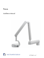
Focus Installation Manual 51775-IMG rev 7 Copyright Code: 51775-IMG rev 7 Date: 19 November 2008 Document code: 51775-IMG1TPH-1 rev 7 Copyright © 11/2008 by PaloDEx Group Oy. All rights reserved. Documentation, trademark and the software are copyrighted with all rights reserved. Under the copyright laws the documentation may not be copied, photocopied, reproduced, translated, or reduced to any electronic medium or machine readable form in whole or part, without the prior written permission of Instrumentarium Dental. The original language of this manual is English. Instrumentarium Dental reserves the right to make changes in specification and features shown herein, or discontinue the product described at any time without notice or obligation. Contact your Instrumentarium Dental representative for the most current information. Manufactured by Instrumentarium Dental Nahkelantie 160 (P.O. Box 20) FI-04300 Tuusula FINLAND Tel. +358 45 7882 2000 Fax. +358 9 851 4048 For service, contact your local distributor. Table of Contents 1 Introduction.................................................................................................................. 1 1.1 General ................................................................................................................. 1 2 Pre installation ............................................................................................................. 3 2.1 Checking the site................................................................................................... 3 2.2 Tools and hardware .............................................................................................. 4 3 Assembly...................................................................................................................... 5 3.1 Mounting system ................................................................................................... 5 3.2 Mounting plate and mounting cover ...................................................................... 6 3.3 Horizontal arm....................................................................................................... 7 3.4 Scissors arm ......................................................................................................... 8 3.4.1 SmartBox cable installation, only valid with Focus SmartBox™ ................ 9 3.5 Friction brake ...................................................................................................... 11 3.5.1 Outer end of the horizontal arm ............................................................... 11 3.5.2 Wall end of the horizontal arm ................................................................. 13 3.6 Leveling the horizontal arm ................................................................................. 13 3.7 Remote control installation.................................................................................. 15 3.8 Connecting to the mains voltage......................................................................... 17 3.8.1 Non-permanent installation to 230 VAC national grid .............................. 19 3.8.2 Permanent installation to 230 VAC national grid...................................... 19 3.8.3 Non-permanent installation to 115 VAC national grid .............................. 21 3.8.4 Permanent installation to 115 VAC national grid...................................... 23 3.9 Dental care unit mounting ................................................................................... 23 3.10 Fastening the covers........................................................................................... 26 3.11 Automatic Exposure Control (AEC).................................................................... 27 3.12 Tests to be done before use ............................................................................... 28 4 Options ....................................................................................................................... 29 4.1 Adjusting the scissors arm .................................................................................. 29 4.2 System configurations......................................................................................... 30 4.2.1 FOCUS Dip Switches............................................................................... 30 4.2.2 Example 1 ................................................................................................ 31 4.2.3 Example 2 ................................................................................................ 32 4.2.4 Example 3 ................................................................................................ 32 4.2.5 Example 4 ................................................................................................ 33 4.2.6 Example 5 ................................................................................................ 33 4.3 Changing of the external fuses ........................................................................... 34 4.4 Wiring options ..................................................................................................... 34 4.5 Using terminal strip for connecting Focus control panel ..................................... 36 5 Dimensions ................................................................................................................ 39 51775-IMG rev 7 Instrumentarium Dental i ii Instrumentarium Dental 51775-IMG rev 7 1 Introduction 1 Introduction 1.1 General FOCUS is a microprocessor controlled intraoral x-ray unit with a HF DC generator, which produces high quality dental images with film or digital sensors. This manual covers the installation of the FOCUS intraoral x-ray unit. For information about how to use the intraoral unit please refer to the Users Manual. A FOCUS Installation Manual and FOCUS User's Manual are shipped with each FOCUS x-ray unit. These manuals and future updates will be available upon request from Instrumentarium Dental. As the manufacturer we strongly recommend that you review both FOCUS manuals before installation. 51775-IMG rev 7 Instrumentarium Dental 1 1 Introduction 2 Instrumentarium Dental 51775-IMG rev 7 2 Pre installation 2 Pre installation 2.1 Checking the site Radiation Shielding: Follow all regulations for radiation shielding of the x-ray room. Wall: The wall and mounting hardware must sustain a pull of 350 lbs./1500N, from each wall bracket bolt. Radiation Safety: During the exposure the operator must follow applicable radiation shielding requirements and stay at least 7 feet (2 meters) from the radiation source. Main voltage: Verify the main voltage (3 wire: single-phase, 115 V or 230 V with protective ground). voltage: Voltage range: 230 VAC line 207 - 253 VAC 115 VAC line 103 - 126 VAC Fuses: Verify that FOCUS power is supplied through a circuit breaker with current rating of max. 16 A slow blow. Voltage: Fuse: 230 VAC line 6,25 A Slow blow 115 VAC Line 6,25 A Slow blow NOTE! Some countries and / or localities may have regulations on fault current protection. Such regulations must be observed. Protective ground: Verify the protective ground. 51775-IMG rev 7 Instrumentarium Dental 3 2 Pre installation 2.2 Tools and hardware NOTE! All screws, bolts, nuts and washers used in FOCUS are in metric sizes. The following tools are required during the installation: Metric Allen wrench set Electric drill, drill bits (8 mm & 10 mm or equal) Mounting hardware for wall bracket Pencil or drawing ink Spirit Level Hammer Anchor driver (concrete wall) Flat screw drivers Pozidrive or phillips screwdrivers (PZD-1 and PZD-2) Pliers Knife or scissors Wrenches, 13 mm and 19 mm Tape measure Make sure that you have all tools and items needed prior to installation. NOTE! This unit is intended for fixed installation only, therefore mobile installation is prohibited. 4 Instrumentarium Dental 51775-IMG rev 7 3 Assembly 3.1 Mounting system Focus mounting system comprises a wall mounting bracket, a single stud wall mounting plate (narrow) and alternatively a 16 inch center stud wall mounting plate (wide). The wall mounting bracket has also several cable connections like the power supply cable connection. Prior to mounting of FOCUS, locate the supporting material of the wall or a mounting surface and choose the mounting system according to the following examples. Mount the unit so that the lower edge of the mounting plate is approximately 47 inches (1100 mm) from the floor. Wall type 51775-IMG rev 7 Anchor Thread 1 K25 Concrete wall HSA expansion anchor M8 2 K30 Concrete wall HKD-S flush anchor M8 3 Wood frame wall 4 Steel frame Screw Washer DIN 912 M8x20 DIN 125-B 8,7 DIN 571 8x90 DIN 125-B 8,7 Installing FOCUS directly to steel framing is not recommended. Recommended is a 2”x6” backing (2”x4” minimum). Then install as per #3 above. Instrumentarium Dental 5 3 Assembly 3.2 Mounting plate and mounting cover If FOCUS is mounted to a wall with 16 inch center studs specify the site of the unit and fasten the mounting plate firmly to the wall. Level the mounting plate. Accurate dimensions for the mounting plate are in chapter 5 Dimensions. Place the mounting cover over the mounting plate. SINGLE STUD MOUNTING IN STEEL FRAME If the wall is constructed with metal studs, a support plate is needed when mounting the unit. Attach a sturdy wooden or steel plate to the opposite side of the steel stud wall and bolt through with the single stud mounting plate. Before mounting the plate make sure that the bolts, which are used for attaching of the unit, are put first to the holes so that they come out visible when the plate is mounted on the wall. 6 Instrumentarium Dental 51775-IMG rev 7 3 Assembly The mounting cover is not needed if the single stud mounting plate is used. 3.3 Horizontal arm Lift the horizontal arm to its place and attach the nuts as shown in the image below. Note that there are two nuts on each side of the wall mounting bracket. Leave the nuts slack to allow for leveling. Adjust the wall mounting arm bracket by means of a level (there is ±2° adjustment allowance). 51775-IMG rev 7 Instrumentarium Dental 7 3 Assembly Level and tighten the wall mounting bracket. 3.4 Scissors arm WARNING! Do not remove the safety strap on the scissors arm before the entire unit is assembled because the scissors arm can open with force. Route the cables of the scissors arm through the hole (bearing) on the horizontal arm. Fit the shaft of the scissors arm in to the hole of the horizontal arm. Assure that the scissors arm is entirely seated into the bearing. Make certain that no space remains between the horizontal arm and the scissors arm assembly. Connect the cables. 8 Instrumentarium Dental 51775-IMG rev 7 3 Assembly 3.4.1 SmartBox cable installation, only valid with Focus SmartBox™ Route the Smartbox cable through the (bearing) on the horizotal arm. Fig 3.1. SmartBox cable through the bearing Fig 3.2. SmartBox cable through the arm Fig 3.3. SmartBox cabel out of the arm 51775-IMG rev 7 Instrumentarium Dental 9 3 Assembly Fig 3.4. Strain relief Route the Smartbox cable through the hole in Focus horizotal arm cover and place the strain relief. Attach the horizontal arm cover. Kuva 3.5. The horizontal arm cover Fig 3.6. The horizontal arm cover 10 Instrumentarium Dental 51775-IMG rev 7 3 Assembly 3.5 Friction brake There are brakes at the both ends of the horizontal arm. The brake at the wall end of the horizontal arm has been factory assembled and adjusted. 3.5.1 Outer end of the horizontal arm Hold the adjustable brake and insert the shorter screw (a) slightly so that the adjustable brake stays in position. Insert two longer screws (b) into the adjustable brake. Leave the screws loose to allow for adjustment of the brake. Adjust the screw (a) to achieve the desired breaking action of the rotation of the scissors arm. Tighten the screws (b) to lock the brake in place. CAUTION! Secure the cables with the cable tie. 51775-IMG rev 7 Instrumentarium Dental 11 3 Assembly Attach the horizontal arm cover and fasten it with the screw at the bottom of the cover. 12 Instrumentarium Dental 51775-IMG rev 7 3 Assembly 3.5.2 Wall end of the horizontal arm NOTE! The brake at the wall end of the horizontal arm has been factory assembled and adjusted. This section can be skipped when installing the unit first time. To adjust the break on the wall end of the horizontal arm first remove the wall mounting bracket cover. Turn the horizontal arm pointing to the left and unscrew the screw of the horizontal arm cover. Loosen the screws b on the top of the brake. Adjust the screw a to achieve the desired breaking action. Replace the covers. 3.6 Leveling the horizontal arm Loosen the nuts on both sides of the horizontal arm bracket (figures below). 51775-IMG rev 7 Instrumentarium Dental 13 3 Assembly Locate the adjuster screw in the adjustment plate below the shaft (Fig. 1). Rotate the adjuster screw observing at the same time the level on the horizontal arm (Fig. 2.). Perform the adjustment until the arm is horizontal. Tighten the four lock screws on the side of the wall mounting bracket to assure that the horizontal arm stays in position. After adjusting the horizontal arm, cut off the safety strap to release the scissors arm. 14 Instrumentarium Dental 51775-IMG rev 7 3 Assembly 3.7 Remote control installation 1. Fasten the back plate of the remote control to the wall with screws. 2. Connect the cable (RJ-45) to the connector X21. 3. Set the cable (RJ-45) inside the ferrite and close it. NOTE! If you need to detach the ferrite when routing the cable in cable rack, open the ferrite with a special tool. 51775-IMG rev 7 Instrumentarium Dental 15 3 Assembly 4. Attach the front cover by pushing into position. 5. Attach the frame of the remote control. 6. Insert screws to the bottom of the remote control. Fig 3.7. The screw places in the back plate of the remote control in Focus V3. Fig 3.8. Ferrite should be tidily inside the panel. It does not push any components or display board. Fig 3.9. Remote control attached to the frame. 16 Instrumentarium Dental Fig 3.10. Plastic cover on the remote control. 51775-IMG rev 7 3 Assembly Fig 3.11. Plastic Cover fastened from the bottom. Fig 3.12. Remote control installed. 3.8 Connecting to the mains voltage Focus is classified either as a non-permanently installed equipment or a permanently installed equipment depending on how it has been installed. The non-permanently installed unit is connected with power supply cord and mains plug when electric current passes through both (F2 and F3) mains fuses in the wall mounting bracket. The permanently installed unit is connected straight to the branch circuit and so that electric current passes through only one mains fuse (F3) in the wall mounting bracket. NOTE! No fuse is used on neutral supply. 51775-IMG rev 7 Instrumentarium Dental 17 3 Assembly WARNING! Only a qualified technician is permitted to carry out these connections. See chapter requirements. 2 for the mains voltage and fuse The unit is normally shipped as follows: All units that are delivered for the national grid of 230VAC, are delivered with a power supply cable. – Instruction for the non-permanent installation are found from section 3.8.1 – Instructions for the permanent installation are found from section 3.8.2 All units that are delivered for the national grid of 115 VAC, are delivered without a power supply cable. – Instructions for the non-permanent installation are found from section 3.8.3 – Instructions for permanent installation are found from section 3.8.4 Use only approved cables and plugs. Mains connector type: 115V / NEMA 6-15P or similar Hospital Grade Power supply cord type: H05VV5-F / AWG 14 (UL 2587) WARNING! Before connecting to the mains, make sure that the cable connections to the fuses are made as instructed. 18 Instrumentarium Dental 51775-IMG rev 7 3 Assembly 3.8.1 Non-permanent installation to 230 VAC national grid The units are delivered with the power supply cable and it can be straight connected to the mains. 3.8.2 Permanent installation to 230 VAC national grid Remove the cable clamp and the power supply cable. Remove the cables F3 and F4. Circuit diagram 1. Cable connection in the permanently installed unit. Plug the cable F32 between the mains switch connector (at the back on the left) and fuse F3. 51775-IMG rev 7 Instrumentarium Dental 19 3 Assembly Plug the blue cord of the cable F33 between mains switch connector slot (which is on the same side as the blue cord from the cable F2) and then connector 2 of the terminal block X91. Plug the black cord of the cable F33 between the fuse F3 and the connector 1 of the terminal block X91. The narrow cable plugs fit the fuses and the wide ones the mains switch connector. Cable markings are found on the cables. NOTE! Do not mix the cable F3 and the fuse F3. The power supply cable is connected to the terminal block (X91) as shown in the image below. Connect neutral and phase into the connectors N and L in the terminal block. Connect the protective ground. WARNING! Only a qualified technician is permitted to carry out this connection. 20 Instrumentarium Dental 51775-IMG rev 7 3 Assembly 3.8.3 Non-permanent installation to 115 VAC national grid Remove the cable F32 from the fuse F3 and from mains switch the connector. Remove also the cable F33 (both cables blue and black) from fuse F3, from the mains switch connector and from the terminal block X91. Cable markings are found on the cables. Circuit diagram 2. Cable connections in a non-permanently installed unit. Plug the blue cord from the cable F4 between the fuse F2 and the connector 2 of the terminal block X91. Plug the black cord from the cable F4 between the fuse F3 and the connector 1 of the terminal block X91. Plug the blue cord from the cable F3 between the fuse F2 and mains switch connector slot, which is on the same side as the blue cord from the cable F2. Plug the black cord from the cable F3 between the fuse F3 and mains switch connector (at the back on the left side). The narrow cable plugs fit the fuses and the wide ones the mains switch connector slot which is on the same side as the black cord in the cable F2. Cable markings are found on the cables. 51775-IMG rev 7 Instrumentarium Dental 21 3 Assembly NOTE! Do not mix the cable F3 and the fuse F3. 1. Twist the part a to the wall mounting bracket. Tighten the part a and the counterpart b together. Tighten the counterpart b by hand as tight as possible and after that tighten it 1/4 round by tool. 2. Route the power supply cable through the cable clamp and finally twist the part c to the part a with strength of 6Nm. Connect neutral and phase into the connectors N and L in the terminal block (X91). Connect the protective ground. Use only the approved cables and plugs. 22 Instrumentarium Dental 51775-IMG rev 7 3 Assembly 3.8.4 Permanent installation to 115 VAC national grid The power supply cable is connected to the terminal block (X91) as shown in the image below. Connect neutral and phase into the connectors N and L in terminal block. Connect the protective ground. 3.9 Dental care unit mounting Focus can be mounted to the dental care unit if a specific unit mount model of Focus (order code 900077) is available. NOTE! The following requirement apply for safe installation on a dental care unit: 1. The the dental care unit must provide bearing (adapter) designed for a dental X-ray with a shaft of diameter of 32 mm +-0.2 mm and a length of 110 mm. 2. The adapter must provide proper and safe means of conducting the Focus main cable of a diameter of 10 mm through the shaft of the X-ray to the generator module installed nearby. 3. The installation must provide tilt adjustment to level and balance the arm. 4. The installation must not allow twisting the X-ray more than 360 degree. 5. The dental care unit must be securely fixed to the floor or other solid construction. The installation must not overbalance if subjected to a force of 220 N (subclause 24.101 of IEC 60601-2-32:1994 Particular requirements for the safety of associated equipment of X-ray equipment) 51775-IMG rev 7 Instrumentarium Dental 23 3 Assembly GENERATOR MODULE INSTALLATION 1. Remove the screws on the side (4 pcs) and at the end (2 pcs) of the generator module and remove the cover. 2. Mount the generator board to the proper place on the dental care unit. SCREW HOLE EXAMPLE LOCATIONS 3. 24 Connect the mains cable to the connection strip. Instrumentarium Dental 51775-IMG rev 7 3 Assembly 4. Connect ground cable to the screw in the bottom. 5. Close the generator module cover and tighten the screws. HORIZONTAL INSTALLATION ARM AND SCISSORS ARM Note: Before installation make sure the proper adapter is available for the pole of the dental care unit. Ask the adapter from the unit supplier. 51775-IMG rev 7 1. Route the main cable to come out from the pole of the dental care unit. Set the horizontal arm into the pole while guiding the cable. 2. Set the scissors arm on the horizontal arm as instructed in chapter 3.4. Scissors arm. 3. Connect the cables and route the inside the horizontal arm. Secure the cables with a cable tie. Instrumentarium Dental 25 3 Assembly 4. Fasten the friction brake as instructed in chapter 3.5. Friction brake. 5. Close the horizontal arm’s end cover and fasten the bottom screw. Fasten the bottom cover. The bottom cover is the same as the spring adjustment cover of which fastening is instructed in the chapter 4.1. Adjusting the scissors arm. HORIZONTAL ARM’S END COVER BOTTOM COVER 3.10 Fastening the covers Place the small U-shaped cover on top of the adjustment part. 26 Instrumentarium Dental 51775-IMG rev 7 3 Assembly If the wire from the remote control is surface mounted, remove a piece from the mounting bracket cover in order to allow the remote control cable to fit in. If the unit is supplied with two remote controls, do the same on the opposite side. Fasten the cover with two screws at the bottom. Fasten the cone. 3.11 Automatic Exposure Control (AEC) AEC function makes it possible to take always perfect images with Sigma sensors without need to adjust exposure time. Connect the external AEC communication cable that comes with FocusLink, between the Sigma electronics and Focus Connection Box Board. Once it is connected the AEC can be used by pressing the AEC button of the Focus remote control. 51775-IMG rev 7 Instrumentarium Dental 27 3 Assembly 3.12 Tests to be done before use Calibration: Calibrate the unit by exposing manually 60 kV, 1.00 s exposures 8 times. This calibrates filament preheat and tube current. Accuracy test: Make one exposure of 10 mm thick Al-plate placed in front of the cone and another exposure without anything between Sigma sensor and the cone. In both cases the exposure level must be between 80 and 100 percent. Exposure level is found in the Cliniview image information dialog. If the exposure level is not within the range of 80 and 100 in either case, calibrate the AEC. Calibration of the AEC is found in service mode 6 (Sr6). Refer to Service Manual for details. Repeatability test: Make two test exposures of a phantom with both kVs, 100200 ms. Exposure time (ms) nor exposure level must not vary more than +/- 10%. Refer to Service Manual, chapter Calibration of AEC for details. Test for exposure time limiter: Aim the beam away from the sensor. Expose with both kVs. Focus should stop the exposure and display H7 error. Refer to Service Manual for details. 28 Instrumentarium Dental 51775-IMG rev 7 4 Options 4 Options 4.1 Adjusting the scissors arm Although the factory scissors arm balance scissors arm, remove below by pressing the the cover out. adjustment usually suffices, the can be adjusted. To adjust the the covers shown in the picture clip with a screwdriver and pulling Turn the nut inside the scissors arm with a screwdriver to adjust the tension of the springs. To increase the tension, turn the nut clockwise. To decrease the tension, turn the nut counter clockwise. After adjusting the scissors arm replace the covers. 51775-IMG rev 7 Instrumentarium Dental 29 4 Options NOTE! If the unit is equipped with a Sigma SmartBox then the adjustment has to be done with at least one Sigmasensor short module connected to the box. 4.2 System configurations 4.2.1 FOCUS Dip Switches Remote Control Description 2 3 Two remote controls in parallel on on Two remote controls in series off off Primary remote control only in use off on Secondary remote control only in use on off Door switch disabled 4 on Connection Box Board Dip switch 1 Position ON (closed) Door signal from Connection Box is connected to ground (Door is closed) OFF (open) Door signal from Connection Box is connected to door switch (Causes Error H3) 2 3 4 5 30 Description unused ON (closed) Enables exposure signal for Remote A (X62). Switch 5 must also be ON OFF (open) Disables exposure signal for Remote A (X62) ON (closed) Enables exposure signal for Remote B (X63). Switch 6 must also be ON OFF (open) Disables exposure signal for Remote B (X63) ON (closed) Enables Remote A (X62) Instrumentarium Dental 51775-IMG rev 7 4 Options Dip switch 6 Position Description OFF (open) Disables Remote A (X62) (Readonly mode) ON (closed) Enables Remote B (X63) OFF (open) Disables Remote B (X63) (Readonly mode) 4.2.2 Example 1 2 remotes daisy-chained, exposure hand / wall switch from each remote, both remote exposure buttons disabled. 51775-IMG rev 7 Instrumentarium Dental 31 4 Options 4.2.3 Example 2 1 remote with exposure button disabled, exposure hand / wall switch from Connection Box, one door switch from Connection Box and one door switch from remote. 4.2.4 Example 3 1 remote with 2 exposure hand / wall switches connected in series, remote exposure button disabled. 32 Instrumentarium Dental 51775-IMG rev 7 4 Options 4.2.5 Example 4 2 remotes using a selector switch, exposure hand / wall switch from each remote. 4.2.6 Example 5 Remote control and external exposure button in series. 51775-IMG rev 7 Instrumentarium Dental 33 4 Options 4.3 Changing of the external fuses Push upward on the fuse base and twist it counterclockwise with a screwdriver. The fuse with the base will come out. Remove the fuse from the base and replace it with the new one. Repeat this with each fuse. Fasten the fuses by pushing the base up and twisting it clockwise with the screwdriver. Use only appropriate fuses. EXTERNAL FUSES: 6,25 A (slow blow) 230 VAC 6,25 A (slow blow) 115 VAC 4.4 Wiring options Standard wiring with power cable (left and right side of the wall mounting bracket). 34 Instrumentarium Dental 51775-IMG rev 7 4 Options The main cable coming out from the wall. Two remote controls with external cables. Connection for the external exposure lamp. 51775-IMG rev 7 Instrumentarium Dental 35 4 Options 4.5 Using terminal strip for connecting Focus control panel Focus unit includes remote control panel cable with RJ-45 connector at both ends. In case it is not possible to pull the RJ-45 connector through conduits at the place of installation the following instructions may be used. In this instruction the terminal strip (X61) at the Focus connection box board is used instead of the RJ-45 terminal connector (X62 or X63). NOTE! Use only the original cable that has been delivered by the manufacturer for installing the remote control panel There are two different types of cables delivered, with different color coding. Check the RJ-45 pin colors and determine cable type used. (see tables below). RJ-45 connector pin number order 36 1. Cut the cable from the connection box board end. 2. Route the cable from the remote control panel to the Focus X-ray unit. 3. Remove cable tubing carefully about 2" (50mm). 4. Strip the wires about 1/3" (8mm). 5. Attach stripped wires to terminal strip X61 as shown in the table below. In case of shielding foil leave it unconnected. 6. Verify connections. Remote control panel cable is a straight through cable (pin 1 connected to pin 1 etc.). Instrumentarium Dental 51775-IMG rev 7 4 Options Cable type 1 (EIA 568A) RJ45 control panel board X21 Connection box board terminal strip X61 1. white/green 1. CS 2. green 2. GND 3. white/orange 3. CLK 4. blue 4. DOUT 5. white/blue 5. BEEP 6. orange 6. DIN 7. white/brown 7. EXP 8. brown 8. PWR Cable type 2 (EIA 568B) RJ45 control panel board X21 connection box board terminal strip X61 1. white/orange 1. CS 2. orange 2. GND 3. white/green 3. CLK 4. blue 4. DOUT 5. white/blue 5. BEEP 6. green 6. DIN 7. white/brown 7. EXP 8. brown 8. PWR 51775-IMG rev 7 Instrumentarium Dental 37 4 Options 38 Instrumentarium Dental 51775-IMG rev 7 5 Dimensions 5 Dimensions Mounting Plate (measures in mm) 51775-IMG rev 7 Instrumentarium Dental 39 5 Dimensions Mounting Plate Cover 40 Instrumentarium Dental 51775-IMG rev 7 5 Dimensions Small Mounting Plate (measures in mm) 75mm (215/16”) 23mm (7/8”) 50mm (115/16”) 60mm (23/8”) 36.5mm (1.44”) 82.5mm (3.25”) 5mm (0.2”) 8mm 31.2mm (11/4”) (0.31”) 102mm (4”) Remote Control Frame (measures in mm) 51775-IMG rev 7 Instrumentarium Dental 41 5 Dimensions 42 Instrumentarium Dental 51775-IMG rev 7 5 Dimensions 51775-IMG rev 7 Instrumentarium Dental 43 5 Dimensions 44 Instrumentarium Dental 51775-IMG rev 7 Instrumentarium Dental reserves the right to make changes in specification and features shown herein, or discontinue the product described at any time without notice or obligation. Contact your Instrumentarium Dental representative for the most current information. Copyright © 11/2008 by PaloDEx Group Oy. All rights reserved. Instrumentarium Dental Nahkelantie 160, FI-04300 Tuusula, Finland Tel. +358 45 7882 2000 Fax +358 9 851 4048 Americas: Instrumentarium Dental Inc. Milwaukee, Wisconsin, U.S.A. Tel. 800 558 6120 Fax 414 481 8665 Focus Installation Manual, English 51775-IMG rev 7 Printed in Finland 11/2008