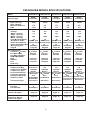
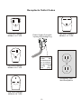
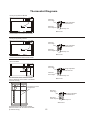
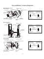
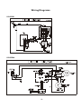
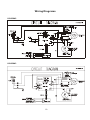
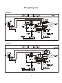
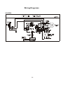
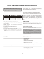
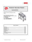
1
Product Information
and Technical Guide
2005 Room Air Conditioners
Model Year Designation “P”
Heavy Duty----------Example FAS155P1A
Thru-The-Wall------Example FAH085P1T
Slider Casement---Exmaple FAK104P1V
Safety update
3
Safe Servicing Practices
4
Model Specifications
5-11
Compressor Overloads
12
Restrictor Tube Data
12
Receptacle Codes
13
Product Dimensions
14
Thermostat Diagrams
15
Fan/Blower Diagrams
16
Wiring Diagrams
17-22
Troubleshooting
23-24
Factory location:RK
ATTENTION SERVICERS!
To get a helping hand, visit the
Frigidaire Web Site at:
http://www.frigidaire.com
User name:
service
Password:
tips
Part No.: 5995434726
May 2005
TABLE OF CONTENTS
Safety Update........................................................................................................3
Safe Servicing Practices .......................................................................................4
Model Specifications ........................................................................................5-11
Compressor Overload Data .................................................................................12
Restrictor Tube Data ...........................................................................................12
Receptacle Outlet Codes .....................................................................................13
Product Dimensions ........................................................................................... 14
Control Thermostat Location Diagrams ...............................................................15
2005 Heavy Duty Thermostat Locations .............................................................15
2005 Thru-The-Wall Thermostat Locations ........................................................ 15
2005 Slider Thermostat Locations .....................................................................15
Fan and Blower Location Diagrams ......................................................................16
Heavy Duty................. ....................................................................................16
Slider Casement..............................................................................................16
Thru-The-Wall.................................................................................................16
Wiring Diagrams .............................................................................................17-22
81902548........................................................................................................17
81902549 .......................................................................................................17
81902381 .......................................................................................................18
81902544........................................................................................................18
81902642........................................................................................................19
81902643........................................................................................................19
81902546........................................................................................................20
81902357........................................................................................................20
81902551........................................................................................................21
81902382........................................................................................................21
81902506 .......................................................................................................22
Troubleshooting .............................................................................................23-24
2
IMPORTANT SAFETY UPDATE
Room Air Conditioners manufactured after August 1st , 2004 are equipped with a new industry
regulated power cord with either of the following in the plug-head or in line:
LCDI: Leakage Current Detection Interrupter
AFCI: Arc-Fault Circuit Interrupter.
All Frigidaire products have an LCDI located in the plug head or in-line.
The power supply cord contains a current device that senses damage to the power cord. To test
your power supply cord does the following:
1. Plug in the Air Conditioner.
2. The power supply cord will have TWO buttons on the plug head. Press the TEST button. You will
notice a click as the RESET button pops out.
3. Press the RESET button. Again you will notice a click as the button engages.
4. The power supply cord is now supplying electricity to the unit. (On some products this is also
indicated by a light on the plug head).
Notes:
Do not use this device to turn the unit on or off.
Always make sure the RESET button is pushed in for correct operation.
The power supply cord must be replaced if it fails to reset when either the TEST button is
pushed, or it cannot be reset. A new one can be obtained from the product manufacturer.
If power supply cord is damaged, it CANNOT be repaired, it MUST be replaced by one obtained
from the product manufacturer.
3
SAFE SERVICING PRACTICES - ALL APPLIANCES
To avoid personal injury or property damage, it is important that Safe Servicing Practices be
observed. The following are some limited examples of safe practices.
1. DO NOT attempt a product repair if you doubt your ability to complete it in a safe and
satisfactory manner.
2. Before servicing or moving an appliance
Remove power cord from electrical outlet, trip circuit breaker to OFF position, or remove fuse
Turn off gas supply
Turn off water supply
3. Never interfere with the proper operation of any safety device.
4. Use only OEM replacement parts cataloged for this appliance. Substitutions may
defeat compliance with safety standards set for home appliances.
5. GROUNDING: The standard color coding for safety ground wires is GREEN, or GREEN with
YELLOW STRIPES. DO NOT use ground leads as current carrying conductors. It is
EXTREMELY important that the service technician reestablish all safety grounds prior to
completing service. Failure to do so will create an electrical hazard.
6. Prior to returning the product to service, ensure that
All electrical connections are correct and secure
All electrical leads are properly dressed and secured away from sharp edges,
high-temperature components, and moving parts
All non-insulated electrical terminals, connectors, heaters, etc. are adequately spaced away
from all metal parts and panels
All safety grounds (both internal and external) are correctly and securely connected
All panels are properly and securely reassembled.
7. In the event that the power cord is damaged, it cannot be repaired. It must be replaced with a
new one from the product manufacturer.
WARNING
This service manual is intended for use by persons having electrical and mechanical training and
a level of knowledge of these subjects generally considered acceptable in the appliance repair
trade. Electrolux Home Products Inc. Cannot be responsible, nor assume any liability, for injury or
damage of any kind arising from the use of this manual.
© 2005 Electrolux Home Products, Inc.
4
FRIGIDAIRE MODEL SPECIFICATIONS
Model
Chassis Type
Capacity Features
BTU - Cooling
BTU - Heating
Moisture Removal
EER
FAS155P1A1 FAS155P1A2
FAS156P1A1 FAS156P1A2 FAS157P1A1
Heavy Duty
Heavy Duty
Heavy Duty
Heavy Duty
Heavy Duty
15100
3.5
10.7
15100
3.5
10.7
15100
3.5
10.7
15100
3.5
10.7
15100
3.5
10.7
Capacity Features
Voltage
115
115
115
115
115
Amps - Cooling
12.3
12.3
12.3
12.3
12.3
Amps - Heating
Watts - Cooling
1400
1400
1400
1400
1400
Watts - Heating
Fuse/Breaker(Amps)
15
15
15
15
15
Receptacle Code
NEMA 5-15
NEMA 5-15
NEMA 5-15
NEMA 5-15
NEMA 5-15
Power Cord Number KT21C7-12(U) KT21C7-12(U) KT21C7-12(U) KT21C7-12(U) KT21C7-12(U)
Power Cord Amps Min
15
15
15
15
15
Wiring Diagram
81902548
81902548
81902548
81902548
81902549
Page #
Page 17
Page 17
Page 17
Page 17
Page 17
Air Flow System
Capacitor- Farads
Fan Motor Mfg.
Fan Motor Number
RPM/CMP(EVAP)
High
Medium
Low
Heat Only
Refrigeration System
Compressor Mfg.
Compressor Number
Compressor Type
Overload Protector
Capacitor- Farads
Refrigerant Charge
Restrictor Tube
Thermostat Type
Installation Instructions
Kit Type
Part Number
Control Thermostat
Location Diagram
Condenser Fan and
Evaporator Blower
Location Diagram
10/250
Heshan
81402116
10/250
Heshan
81402116
10/250
Heshan
81402116
10/250
Heshan
81402116
10/250
Heshan
81402116
900/450
-
900/450
-
900/450
-
900/450
-
900/450
-
Sanyo
1304436
Rotary
LG
1304559
Rotary
Sanyo
1304436
Rotary
LG
1304559
Rotary
Sanyo
1304436
Rotary
MRA98693-9200
MRA4720-12027
MRA98693-9200 MRA4720-12027
MRA98693-9200
40
F/250V
47.3
813034550
Electronic
60u/250V
47.3
813034139
Electronic
40
A
819042102
A
819042102
A
819042102
A
819042102
A
819042102
F/250V
47.3
813034550
Electronic
60u/250V
47.3
813034139
Electronic
40
F/250V
47.3
813034550
Electronic
Page 15
Page 15
Page 15
Page 15
Page 15
Page 16
Page 16
Page 16
Page 16
Page 16
5
FRIGIDAIRE MODEL SPECIFICATIONS
Model
Chassis Type
Capacity Features
BTU - Cooling
BTU - Heating
Moisture Removal
EER
FAS157P1A2 FAS182P2A1 FAS184P2A1 FAS185P2A1 FAS186P2A1
Heavy Duty
15100
3.5
10.7
Heavy Duty
Heavy Duty
18000/17800 18000/17800
5.3
5.3
9.7
9.7
Heavy Duty
Heavy Duty
18500/18200
5.5
10.7
18500/18200
5.5
10.7
Capacity Features
115
230/208
230/208
230/208
230/208
Voltage
Amps - Cooling
12.3
7.6/8.4
8.1/9.0
7.6/8.4
8.1/9.0
Amps - Heating
Watts - Cooling
1400
1730/1700
1850/1830
1730/1700
1850/1830
Watts - Heating
Fuse/Breaker(Amps)
15
15
15
15
15
Receptacle Code
NEMA 5-15
NEMA 6-15
NEMA 6-15
NEMA 6-15
NEMA 6-15
Power Cord Number KT21C7-12(U) KT21C7-13(U) KT21C7-13(U) KT21C7-13(U) KT21C7-13(U)
Power Cord Amps Min
15
15
15
15
15
Wiring Diagram
81902549
81902542
81902381
81902542
81902544
Page #
Page 17
Page 19
Page 18
Page 19
Page 18
Air Flow System
Capacitor- Farads
Fan Motor Mfg.
Fan Motor Number
RPM/CMP(EVAP)
High
Medium
Low
Heat Only
Refrigeration System
Compressor Mfg.
Compressor Number
Compressor Type
Overload Protector
Capacitor- Farads
Refrigerant Charge
Restrictor Tube
Thermostat Type
Installation Instructions
Kit Type
Part Number
Control Thermostat
Location Diagram
Condenser Fan and
Evaporator Blower
Location Diagram
6
F/450V
Heshan
8140270
6
F/450V
Heshan
81402117
6
F/450V
Heshan
81402117
6
900/450
-
1050/470
850/350
-
1050/470
850/350
-
1050/470
-
1050/470
-
LG
1304559
Rotary
Samsung
1304462
Rotary
Samsung
1304462
Rotary
Samsung
1304462
Rotary
Samsung
1304462
Rotary
10/250
Heshan
81402116
F/450V
Heshan
81402117
MRA4720-12027 MRA12133-12007 MRA12133-12007 MRA12133-12007 MRA12133-12007
60u/250V
47.3
813034139
Electronic
35
F/450V
43.7
813034653
Mechanical
35
F/450V
43.7
813034653
Electronic
35
F/450V
52.2
813034653
Electronic
35
A
819042102
A
819042102
A
819042102
A
819042102
A
819042102
Page 15
Page 15
Page 15
Page 15
Page 15
Page 16
Page 16
Page 16
Page 16
Page 16
6
F/450V
52.2
813034653
Electronic
FRIGIDAIRE MODEL SPECIFICATIONS
Model
Chassis Type
Capacity Features
BTU - Cooling
BTU - Heating
Moisture Removal
EER
FAS187P2A1 FAS18EP2A1 FAS225P2A1 FAS226P2A1
Heavy Duty
Heavy Duty
Heavy Duty
Heavy Duty
18500/18200
5.5
10.7
18000/17800
16000/13000
5.5
9.7
22000/21600
6.5
9.4
22000/21600
6.5
9.4
Capacity Features
230/208
Voltage
230/208
230/208
230/208
Amps - Cooling
7.6/8.4
8.1/9.0
9.9/10.9
9.9/10.9
Amps - Heating
19.2/21.0
Watts - Cooling
1730/1700
1855/1840
2340/2300
2340/2300
Watts - Heating
4900/4000
Fuse/Breaker(Amps)
30
15
15
15
Receptacle Code
NEMA 6-30
NEMA 6-15
NEMA 6-15
NEMA 6-15
Power Cord Number KT21C7-13(U) KT21C8-04(U) KT21C8-03(U) KT21C8-03(U)
Power Cord Amps Min
20
15
20
20
Wiring Diagram
81902547
81902544
81902542
81902542
Page #
Page 19
Page 18
Page 19
Page 19
Air Flow System
Capacitor- Farads
Fan Motor Mfg.
Fan Motor Number
RPM/CMP(EVAP)
High
Medium
Low
Heat Only
Refrigeration System
Compressor Mfg.
Compressor Number
Compressor Type
Overload Protector
Capacitor- Farads
Refrigerant Charge
Restrictor Tube
Thermostat Type
6
F/450V
Heshan
81402117
6
F/450V
Heshan
81402117
6
F/450V
Heshan
81402117
6
F/450V
Heshan
81402117
1050/470
-
1050/470
-
1050/480
-
1050/480
-
Samsung
1304462
Rotary
Samsung
1304462
Rotary
LG
1304579
Rotary
3HM408
40 F/450V
52.9
813034888
Electronic
35
F/450V
52.2
813034653
Electronic
35
F/450V
43.7
813034653
Electronic
LG
1304579
Rotary
3HM408
40 F/450V
52.9
813034888
Electronic
A
819042102
A
819042102
A
819042102
A
819042102
Control Thermostat
Location Diagram
Page 15
Page 15
Page 15
Page 15
Condenser Fan and
Evaporator Blower
Location Diagram
Page 16
Page 16
Page 16
Page 16
Installation Instructions
Kit Type
Part Number
MRA12133-12007 MRA12133-12007
7
FRIGIDAIRE MODEL SPECIFICATIONS
Model
Chassis Type
Capacity Features
BTU - Cooling
BTU - Heating
Moisture Removal
EER
FAS255P2A1 FAS256P2A1 FAS25EP2A1 FAS294P2A1 FAS296P2A1
Heavy Duty
Heavy Duty
Heavy Duty
Heavy Duty
25000/24700
7.6
9.4
25000/24700
7.6
9.4
25000/24700
16000/13000
7.6
9.4
28500/28000 28500/28000
8.6
8.6
8.5
8.5
Heavy Duty
Capacity Features
230/208
Voltage
230/208
230/208
230/208
230/208
Amps - Cooling
11.4/12.6
14.4/15.9
11.4/12.6
14.4/15.9
11.4/12.6
Amps - Heating
19.2/21.0
Watts - Cooling
2660/2630
3350/3300
2660/2630
3350/3300
2660/2630
Watts - Heating
4900/4000
Fuse/Breaker(Amps)
30
20
30
20
30
Receptacle Code
NEMA 6-30
NEMA 6-20
NEMA 6-20
NEMA 6-30 NEMA 6-30
Power Cord Number KT21C8-03(U) KT21C8-03(U) KT21C8-04(U)KT21C8-04(U) KT21C8-04(U)
Power Cord Amps Min
20
20
20
20
20
Wiring Diagram
81902643
81902642
81902546
81902642
81902546
Page #
Page 19
Page 19
Page 20
Page 19
Page 20
Air Flow System
Capacitor- Farads
Fan Motor Mfg.
Fan Motor Number
RPM/CMP(EVAP)
High
Medium
Low
Heat Only
6
F/450V
Heshan
81402117
6
F/450V
Heshan
81402117
6
F/450V
Heshan
81402117
7.5 F/450V
Heshan
81402118
7.5 F/450V
Heshan
81402118
1050/480
-
1050/480
-
1050/480
-
1150/500
-
1150/500
-
Refrigeration System
Compressor Mfg.
Samsung
Samsung
Samsung
Samsung
Samsung
Compressor Number
1304606
1304606
1304608
1304608
1304606
Compressor Type
Rotary
Rotary
Rotary
Rotary
Rotary
Overload Protector
3HM208-41
3HM208-41
3HM535-41
3HM535-41
3HM208-41
Capacitor- Farads
50uF/400V
50uF/400V
50uF/400V
50uF/400V
50uF/400V
Refrigerant Charge
50.0
50.0
48.7
48.7
50.0
Restrictor Tube
813034709/10* 813034709/10* 813034709/10* 813034751-54# 813034751-54#
Electronic
Electronic
Thermostat Type
Electronic
Electronic
Electronic
Installation Instructions
Kit Type
Part Number
A
819042102
A
819042102
A
819042102
A
819042102
A
819042102
Control Thermostat
Location Diagram
Page 15
Page 15
Page 15
Page 15
Page 15
Condenser Fan and
Evaporator Blower
Location Diagram
Page 16
Page 16
Page 16
Page 16
Page 16
* Restrictor tube part numbers: 813034709 & 813034710.
# Restrictor tube part numbers: 813034751, 813034752, 813034753 & 813034754.
8
FRIGIDAIRE MODEL SPECIFICATIONS
Model
Chassis Type
FAK085P7V1 FAK104P1V1 FAK107P1V1 FAK124P1V1 FAK127P1V1
Slider
Casement
Slider
Casement
Slider
Casement
Slider
Casement
Slider
Casement
8000
6.5
10.5
10000
6.5
9.5
10000
6.5
9.5
12000
6.5
9.5
12000
6.5
9.5
Capacity Features
BTU - Cooling
BTU - Heating
Moisture Removal
EER
Capacity Features
Voltage
115
115
115
115
115
Amps - Cooling
7.3
9.6
9.6
11. 2
11. 2
Amps - Heating
Watts - Cooling
760
1050
1050
1260
1260
Watts - Heating
Fuse/Breaker(Amps)
15
15
15
15
15
Receptacle Code
NEMA 5-15
NEMA 5-15
NEMA 5-15
NEMA 5-15
NEMA 5-15
Power Cord Number KT21C6-27(U) KT21C6-27(U) KT21C6-27(U) KT21C7-12(U) KT21C7-12(U)
Power Cord Amps Min
13
13
13
15
15
Wiring Diagram
81902357
81902357
81902357
81902357
81902357
Page #
Page 20
Page 20
Page 20
Page 20
Page 20
Air Flow System
Capacitor- Farads
Fan Motor Mfg.
Fan Motor Number
RPM/CMP(EVAP)
High
Medium
Low
Heat Only
Refrigeration System
Compressor Mfg.
Compressor Number
Compressor Type
Overload Protector
Capacitor- Farads
Refrigerant Charge
Restrictor Tube
8
F/250V
Heshan
8140296
8
F/250V
Heshan
8140262
8
F/250V
Heshan
8140262
8
F/250V
Heshan
8140262
8
1280/210
1100/190
1000/160
-
1380/270
1200/245
1050/205
-
1380/270
1200/245
1050/205
-
1380/270
1200/245
1050/205
-
1380/270
1200/245
1050/205
-
LG
1304443
Rotary
LG
1304443
Rotary
LG
1304447
Rotary
LG
1304447
Rotary
Panasonic
1304599
Rotary
F/250V
Heshan
8140262
MRA98503or 98706 MRA12061-12026 MRA12061-12026 MRA12053-12027 MRA12053-12027
50
Thermostat Type
35uF/250V
21.9
813034688/
813035382
Electronic
Installation Instructions
Kit Type
Part Number
F/250V
23.3
813032374
50
Electronic
Electronic
Electronic
Electronic
V
819042237
V
819042237
V
819042237
V
819042237
V
819042237
Control Thermostat
Location Diagram
Page 15
Page 15
Page 15
Page 15
Page 15
Condenser Fan and
Evaporator Blower
Location Diagram
Page 16
Page 16
Page 16
Page 16
Page 16
9
F/250V
23.3
813032374
50
F/250V
23.3
50
F/250V
23.3
813034472/8130 813034472/8130
34774/813034775 34774/813034775
FRIGIDAIRE MODEL SPECIFICATIONS
Model
FAH085P1T1
Chassis Type
Thru-the-wall Thru-the-wall Thru-the-wall Thru-the-wall
Capacity Features
BTU - Cooling
BTU - Heating
Moisture Removal
EER
8000
1.8
9.4
FAH08EP1T1 FAH105P1T1
8000
4000
1.8
9.4
10000
2.8
9.4
FAH105P2T1
10000/9800
2.8
9.4
Capacity Features
Voltage
115
115
115
230/208
Amps - Cooling
7.4
7.4
9.5
4.8/5.5
Amps - Heating
11. 2
Watts - Cooling
850
850
1065
1065/1040
Watts - Heating
1250
Fuse/Breaker(Amps)
15
15
15
15
Receptacle Code
NEMA 5-15
NEMA 5-15
NEMA 5-15
NEMA 6-15
Power Cord Number KT21C7-15(U) KT21C7-15(U) KT21C7-15(U) KT21C7-14(U)
Power Cord Amps Min
15
15
15
15
Wiring Diagram
81902357
81902551
81902357
81902382
Page #
Page 20
Page 21
Page 20
Page 21
Air Flow System
Capacitor- Farads
Fan Motor Mfg.
Fan Motor Number
RPM/CMP(EVAP)
High
Medium
Low
Heat Only
12uF/450V
Heshan
8140297
12uF/450V
Heshan
8140297
12uF/450V
Heshan
8140297
3.5uF/450V
Heshan
8140298
1010/280
910/240
810/205
-
1010/280
910/240
810/205
-
1010/250
910/220
810/185
-
1010/250
910/220
810/185
-
Refrigeration System
Compressor Mfg.
Hili
Hili
LG
Compressor Number
1304607
1304607
1304443
Compressor Type
Rotary
Rotary
Rotary
Overload Protector MRA98883-9200 MRA98883-9200 MRA12061-12026
50 F/250V
50 F/250V
50 F/250V
Capacitor- Farads
24.7
20.5
20.5
Refrigerant Charge
813034403
813034737
813034737
Restrictor Tube
Electronic
Electronic
Electronic
Thermostat Type
Installation Instructions
Kit Type
Part Number
LG
1304564
Rotary
MRA12054-12026
30
F/450V
24.7
813034747
Electronic
T
819042236
T
819042236
T
819042236
T
819042236
Control Thermostat
Location Diagram
Page 15
Page 15
Page 15
Page 15
Condenser Fan and
Evaporator Blower
Location Diagram
Page 16
Page 16
Page 16
Page 16
10
FRIGIDAIRE MODEL SPECIFICATIONS
Model
FAH10EP2T1 FAH125P2T1 FAH12EP2T1
Chassis Type
Thru-the-wall Thru-the-wall Thru-the-wall
Capacity Features
BTU - Cooling
BTU - Heating
Moisture Removal
EER
10000/9800
10000/8500
2.8
9.4
12000/11750
3.6
9.4
12000/11700
10000/8500
3.6
9.4
Capacity Features
Voltage
230/208
230/208
230/208
Amps - Cooling
4.8/5.5
5.9/6.4
5.9/6.4
Amps - Heating
13.2/12.0
13.7/12.7
Watts - Cooling
1065/1040
1275/1250
1275/1250
Watts - Heating
3050/2500
3120/2600
Fuse/Breaker(Amps)
15
15
15
Receptacle Code
NEMA 6-15
NEMA 6-15
NEMA 6-15
Power Cord Number KT21C7-14(U) KT21C7-14(U) KT21C7-14(U)
Power Cord Amps Min
15
15
15
Wiring Diagram
81902506
81902506
81902382
Page #
Page 22
Page 22
Page 21
Air Flow System
Capacitor- Farads
Fan Motor Mfg.
Fan Motor Number
RPM/CMP(EVAP)
High
Medium
Low
Heat Only
Refrigeration System
Compressor Mfg.
Compressor Number
Compressor Type
Overload Protector
Capacitor- Farads
Refrigerant Charge
Restrictor Tube
Thermostat Type
Installation Instructions
Kit Type
Part Number
Control Thermostat
Location Diagram
Condenser Fan and
Evaporator Blower
Location Diagram
3.5uF/450V
Heshan
8140298
3.5uF/450V
Heshan
8140298
3.5uF/450V
Heshan
8140298
1010/250
910/220
810/185
-
1010/260
910/230
810/195
-
1010/260
910/230
810/195
-
LG
1304564
Rotary
LG
1304580
Rotary
LG
1304580
Rotary
MRA12054-12026 MRA12124-12026 MRA12124-12026
30
F/450V
24.7
813034747
Electronic
30
F/450V
26.1
813034230
Electronic
30
T
819042236
T
819042236
T
819042236
Page 15
Page 15
Page 15
Page 16
Page 16
Page 16
11
F/450V
26.1
813034230
Electronic
Compressor Overload Data
Supplier Part#
Used With
Compressor
Opening Temp
Closing Temp
Short Time Tripat 25
Test Amp Opeing Time-Sec
QXE-19(F)
165
5
69
11
43.0
MRA4720-12027
QK208CAA
150
5
69
11
50.3
MRA12133-12007
48D172IUAEL
150
75
97
11
11
26.0
MRA98693-9200
11
5
7
5
QP306KBB
165
5
5
3HM208-41
55A260IU2JM
165
5
90
11
59.0
3~10
3HM535-41
55A300IU1JM
165
5
92
11
67.0
10
5
2R12S3R126AUB
160
5
80
11
26.0
11
5
3HM408
MRA98503or 98706
54.0
11 5
10 5
QK141CCD
150
5
61
11
40.5
11
5
MRA12053-12027
QK164CBF
150
5
61
11
41.5
11
5
MRA98883-9200
SD104SW-P3AU
160
5
70
11
25.0
11
5
MRA12054-12026
QK141KBH
155
7
69
11
14.5
11
5
MRA12124-12026
QK164KBK
145
5
69
11
19.0
11
5
MRA12061-12026
*Terminal to overload must withstand 10 pounds pull test.
Restrictor Tube Data
Style#
Length
O.D.
I.D.
Mpa
813034550
813034139
813034653
813034888
813034709
813034710
813034751
813034752
813034753
813034754
813034688
813035382
813032374
813034472
813034774
813034775
813034737
813034403
813034747
813034230
800
800
550
400
1000
850
450
650
650
650
600
520
400
1100
800
950
600
550
550
500
0.106
0.106
0.106
0.106
0.106
0.106
0.106
0.106
0.106
0.106
0.106
0.106
0.106
0.106
0.106
0.106
0.106
0.106
0.106
0.106
0.055
0.055
0.039
0.039
0.047
0.047
0.039
0.039
0.039
0.039
0.039
0.039
0.039
0.039
0.039
0.039
0.039
0.039
0.039
0.039
0.7
0.7
0.7
0.7
0.7
0.7
0.7
0.7
0.7
0.7
0.7
0.7
0.7
0.7
0.7
0.7
0.7
0.7
0.7
0.7
12
CFM Dry Air
Minimum Maximum
1.809
1.901
1.809
1.901
0.910
1.005
1.007
1.095
1.148
1.289
1.205
1.298
0.873
0.958
0.852
0.946
0.852
0.946
0.852
0.946
0.869
0.950
0.933
1.021
1.007
1.095
0.675
0.756
0.781
0.865
0.735
0.817
0.887
0.961
0.912
1.007
0.912
1.007
0.936
1.025
Receptacle Outlet Codes
115 Volts-15Amps
NEMA 5-15 TYPE
230 Volts-20Amps
NEMA 6-20 TYPE
Power Supply Cord with
3-prong Grounding Plug
230 Volts-15Amps
NEMA 6-15 TYPE
DO
NOT
under
any
circmstances
cut or remove
the grounding
prong
from
this
plug.
Grounding Type
Wall Receptacle
230 Volts-30Amps
NEMA 6-30 TYPE
13
Product Dimensions
Heavy Duty Slide Out Top Control
Top Air Discharge
Slider Casement
14 1/2”
26 1/2”
20 1/2”
18 1/2”
25 1/2”
23”
Maximum Wall Thickness 9”
Thru The Wall
No Side Louvers
24”
14 1/2”
20”
Maximum Wall Thickness 22”
14
Thermostat Diagrams
Heavy Duty Electric Model
5th Row
From Top
Sensing Cap Must
Not Touch Fins
6th Row
From Top
20”
Evap. Fin
Side View
Air thermistor and thermistor holder
Heavy Duty Rotary Model
5th Row
From Top
Sensing Cap Must
Not Touch Fins
6th Row
From Top
20”
Evap. Fin
Side View
Air thermostat and thermostat holder
Thru The Wall
3th Row
From Top
Sensing Cap Must
Not Touch Fins
2”
4th Row
From Top
Air thermistor and thermistor holder
(Place between 3th and 4th rows tubes
up from the top.)
Evap. Fin
Side View
Center line of the
evaporator
3th Row
From Top
Sensing Cap Must
Not Touch Fins
4th Row
From Top
Evap. Fin
Side View
Air thermistor and thermistor holder
(Place between 3th and 4th rows tubes
up from the top.)
15
Fan and Blower Location Diagrams
Heavy Duty Top Control
Evaporator Side
Condenser Side
Left Bulkhead
Top Fan Shell
Counterclockwise
Nut
Blower Wheel
To be fully seated
against motor shaft.
(bottom out on shaft)
Clockwise
Nut
Condenser Fan
To be fully seated
against motor shaft.
(bottom out on shaft)
Motor Shaft
Motor
Motor
Bracket
Blower Wheel
(Centrifugal Fan)
Fan Blade
(Axial Fan)
Oriented
Board
Clockwise
Nut
Evaporator Side
Counterclockwise
Nut
Condenser Side
Slider Casement
Evaporator Side
Fan Shell
Condenser Side
Bulkhead
Blower Wheel
To be fully seated
against motor shaft.
(bottom out on shaft)
Condenser Fan
To be fully seated
against motor shaft.
(bottom out on shaft)
Motor Shaft
Motor
Fan Blade
(Axial Fan)
Blower Wheel
(Centrifugal Fan)
Motor
Bracket
5/16”
Clockwise
Nut
Condenser Side
5/16”
Counterclockwise
Nut
Evaporator Side
5/16”
Base
Thru The Wall
Evaporator Side
Top Fan Shell
Condenser Side
Connection
Bar
Motor
Counterclockwise
Nut
Clockwise
Nut
Blower Wheel
To be fully seated
against motor shaft.
(bottom out on shaft)
Condenser Fan
To be fully seated
against motor shaft.
(bottom out on shaft)
Motor Shaft
Blower Wheel
(Centrifugal Fan)
Motor
Bracket
Left Bulkhead
Fan Blade
(Axial Fan)
Oriented
Board
16
Counterclockwise
Nut
Evaporator Side
Clockwise
Nut
Condenser Side
Wiring Diagrams
81902548
81902549
17
Wiring Diagrams
81902381
81902544
18
Wiring Diagrams
81902642
81902643
19
Wiring Diagrams
81902546
81902357
20
Wiring Diagrams
81902551
81902382
21
Wiring Diagrams
81902506
22
ROOM AIR CONDITIONERS TROUBLESHOOTING
CAUTION: Review Safe Servicing Practices in
the front of this manual before attempting
diagnostic procedures and repairs.
AIR CONDITIONER VOLTAGE LIMITS
NAMEPLATE
MINIMUM
MAXIMUM
RATING
115VAC
103.5VAC
126.5VAC
230VAC
207VAC
253VAC
208/230VAC
197.5VAC
253VAC
AIR CONDITIONER VOLTAGE LIMITS
Low voltage is a common cause of trouble in the operation of any
room air conditioner.
Low voltage can also be the direct result of inadequately wired
circuits, extension cords, or loose fuses and connections to the
power supply. Voltage may also be a general condition in the
area (a responsibility of the power company).
All units will start and run on the minimum voltage stated in the
chart to the left, and will perform satisfactorily if the voltage
remains constant. Low voltage caused by defective wiring will
not remain constant under load.
To test for low voltage, use a reliable meter with sufficient
capacity to measure the required voltage. Take measurements
at the electric power entry point and at the electric outlet serving
the air conditioner. Take readings with the unit off, while the unit
is starting, and again while the unit is running. The lowest
reading should not drop below the lowest value listed in the
chart.
HIGH VOLTAGE
High voltage can be equally troublesome, causing motors to
overheat, cycle on their protectors, or break down electrically.
This problem can only be solved by the power company.
Improper voltage may cause one or more of the following
problems:
1. Unit will not start.
2. Compressor motor cycling on motor protector.
3. Premature failure of motor protector.
4. Blown fuses.
5. Premature failure of compressor or fan motor.
6. Noticeable dimming of lights when air conditioner is running.
7. Evaporator icing. Low voltage may reduce fan speed resulting
in inadequate air flow over evaporator, thereby allowing it to
ice up.
This control is not repairable. If any component in the control is
defective, the entire control must be replaced.
SYMPTON
POSSIBLE CAUSE
Fan motor will not run.
1.
2.
3.
4.
5.
6.
7.
8.
9.
Fan motor runs intermittently.
1. Cycle on motor protector.
Fan motor noisy.
1.
2.
3.
4.
ELECTRONIC CONTROL
IMPORTANT NOTICE: Repair or replace any malfunctioning
line voltage component before testing or replacing the
electronic control. DO NOT assume a service problem is
directly caused by the electronic control system. A line voltage
component (including power cord and wiring) that has opened,
shorted, grounded or otherwise malfunctioned, may have
created a service problem.
23
No power.
Power supply cord.
Selector switch.
Energy sawing switch(if applicable).
Electronic control(if applicable).
Wire disconnected or connection loose.
Capacitor.(Dischage capacitor before testing.)
Defective fan motor windings.
Will not rotate. Fan blade hitting shroud or blower wheel hitting
scroll. (Motor cycles on overload.)
Condenser fan blade or evaporator blower wheel.
Loose power clamp or set screw.
Worn bearings.
Grommets(if applicable).
SYMPTON
POSSIBLE CAUSE
Compressor will not run, but fan motor runs.
1. Voltage.
2. Wiring.
3. Selector switch.
4. Temperature control.
5. Capacitor. (Discharge capacitor before testing.)
6. Compressor.
7. Motor protector(external).
8. Motor protector(internal).
9. Electronic control(if applicable).
10. Hard starting.
Compressor cycles on motor protector.
1.
2.
3.
4.
5.
6.
7.
8.
9.
Voltage.
Motor protector(external).
Motor protector(internal).
Fan motor.
Condenser air flow restriction.
Condenser fins damaged.
Capacitor.
Wiring.
Refrigerant system.
Insufficient cooling.
1.
2.
3.
4.
Low capacity.
Air filter.
Exhaust door open.
Unit undersized.
Excessive noise.
1.
2.
3.
4.
5.
Evaporator blower wheel.
Condenser wheel.
Copper tubing.
Compressor internal noise.
Fan motor.
Excessive water or condensation.
1. Unit operating under extremely high humidity conditions.
No cooling.
1. Refrigerant leak.
Unit is cooling but room is not cool.
1. Amps and watts.
2. Sealed refrigeration system.
Wattage decreases slowly until abnormally low.
1. Undercharged, restricted strainer or plugged restrictor tube.
Wattage decreases immediately.
1. No refrigerant
2. Compressor defective.
Wattage continues high.
1. Refrigerant overcharge.
Evaporator coil partially frosted.
1. System low on refrigerant.
Evaporator completely iced.
1. Low outside temperature.
No heat.
1.
2.
3.
4.
5.
6.
7.
8.
Fan motor will not rotate during heat cycle.
(Heat/Cool models only.)
1. Thermostatic drain valve.(what level control, if applicable.)
24
No power.
Selector switch position.
Temperature control position.
Fan motor.
Heating element.
Selector switch.
Temperature control.
Terminals and connectors.