1
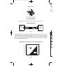
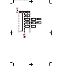
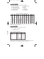
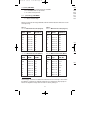
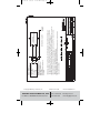
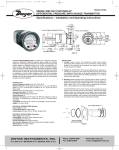
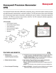
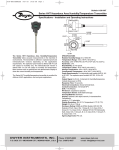
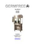
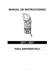
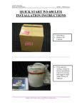
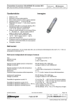
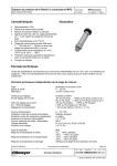
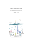
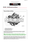
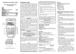
A-25:B-32
5/8/09
11:22 AM
Page 1
Bulletin A-25
Series ISDP Intrinsically Safe Differential Pressure Transmitter
Specifications - Installation and Operating Instructions
DWYER INSTRUMENTS, INC.
Phone: 219/879-8000
www.dwyer-inst.com
P.O. BOX 373 • MICHIGAN CITY, IN 46361, U.S.A.
Fax: 219/872-9057
e-mail: [email protected]
A-25:B-32
5/8/09
11:22 AM
Page 2
DIMENSIONS
4-23/32
[120]
4-9/64
[105.17]
25/32
[21.18]
3-7/16
[87.12]
1-15/16
[48.97]
2-31/32
[75.39]
BRACKETS
ARE OPTIONAL
4-23/32
[120]
5-7/32
[132.54]
1-5/16
[33]
1-17/32
[38.61]
1-45/64
[43.18]
45/64
[17.78]
4X ø3/16 [4.76] CLEARANCE
HOLES FOR MOUNTING
Shown with Optional A-438 Mounting Bracket
MOUNTING HOLE
PATTERN
1-5/32
[29.59]
4-1/8
[105]
3-17/64
[83]
SPE
Serv
Wett
RTV
icone
Hou
Acc
warm
Stab
Pres
5˝: 5
Tem
Com
Ther
Pow
Outp
Zero
Res
Disp
Elec
Proc
Enc
Mou
Size
Weig
Age
GR:
2001
Intri
OPTIONAL A-438 BRACKET
MOUNTING DIAGRAM
#8-36 SLOTTED MACHINE SCREW
Enti
Ui =
Ii = 9
Ci =
Li =
Pi =
Intri
CLA
CLA
CLA
#8 LOCK
WASHER
BRACKET ASSEMBLY
1
Note
1. R
2. R
m
3. U
4. In
A
5. T
h
A-25:B-32
CE
5/8/09
11:22 AM
Page 3
SPECIFICATIONS
Service: Air and non-corrosive gases.
Wetted Materials: Ranges 5˝ and greater: glass, PVC, silicon, alumina ceramic, epoxy,
RTV, gold, aluminum, stainless steel and nickel; Ranges 1˝ and lower: stainless steel, silicone, gold and ceramic.
Housing Materials: Aluminum, glass.
Accuracy: ±0.5% at 77°F (25°C) including hysteresis and repeatability (after 1 hour
warm-up).
Stability: < ±1% per year.
Pressure Limits: Ranges ≤ 2.5 in. w.c. = 2 psi;
5˝: 5 psi; 10˝: 5 psi; 25˝: 5 psi; 50˝: 5 psi; 100˝: 9 psi.
Temperature Limits: 32 to 140°F (0 to 60°C).
Compensated Temperature Limits: 32 to 140°F (0 to 60°C).
Thermal Effects: 0.020%/°F (0.036/°C) from 77°F (25°C).
Power Requirements: 10-35 VDC.
Output Signal: 4-20 mA DC.
Zero & Span Adjustments: Accessible via menus.
Response Time: 250 ms (dampening set to 1).
Display: 4 digit LCD 0.6˝ height.
Electrical Connections: M12 4 PIN Connector.
Process Connections: 1/8 female NPT.
Enclosure Rating: Designed to meet NEMA 4x (IP66).
Mounting Orientation: Mount unit in horizontal plane.
Size: 4.73˝ x 4.73˝ x 3.43˝ (120 mm x 120 mm x 87.1 mm).
Weight: 2 lb 10 oz (1.19 kg).
Agency Approvals: FM, C-FM Intrinsically Safe CL1 Div 1 GR: A, B, C, D; CL2 Div 1
GR: E, F, G; CL3 Div 1 CE. CENELEC EN 61326/55024: 2003; IEC 61000-4-2/3/4/6:
2001/2006/2004/2005; CENELEC EN 55011: 2006; 2004/108/EC EMC Directive.
Intrinsic Safety Information
Entity Parameters
Ui = 28VDC
Ii = 93mA
Ci = 22 nF
Li = 400 uH
Pi = 651mW
Intrinsically Safe for the following hazardous areas:
CLASS I DIV. 1 GROUPS A, B, C, D
CLASS II DIV. 1 GROUPS E, F, G
CLASS III DIV. 1 T4
Notes:
1. Remove power from the instrument before carrying out any servicing.
2. Return the instrument to the manufacturer for any repair. Any unauthorized repairs
may impair the intrinsic safety of the instrument.
3. Use only FM approved Associated Apparatus.
4. Install in accordance with ANSI/ISA RP12.06.01, the National Electric Code
ANSI/NFPA 70, in the US, and the Canadian electrical code in Canada.
5. The earth terminal on the housing must be wired to a local earth ground in the
hazardous area.
2
A-25:B-32
5/8/09
11:22 AM
Page 4
INST
Mou
or vi
M-12 Connector
Pres
Use
with
2
3
1
+
4
A-231 M-12 Cable Colors
PIN 1 is Brown (positive)
PIN 3 is Blue (negative)
Use Model A-231 shielded cable with 4 pin Female M-12 connection.
2-WIRE CONNECTION
ISDP
TRANSMITTER
POWER
SUPPLY
10-35 VDC
mA
RECEIVER
SP/AL
SP/AL
SP/AL
Fig. C
SP/AL
MENU
2-Wire Operation- An external power supply delivering 10 - 35 VDC with minimum current
capability of 40 mA DC (per transmitter) must be used to power the control loop. See Fig.
C for connection of the power supply, transmitter, and receiver. The range of the appropriate receiver load resistance (RL) for the DC power supply voltage available is expressed
by the formula and graph in Fig. D.
POWER SUPPLY VOLTAGE - VDC (2-WIRE CONNECTION)
MENU
MENU
ME
ME
MENU
UP
ARR
E
E
E
TOTAL RECEIVER RESISTANCE (Ω)
DOW
ARR
1500
1400
1300
1200
1100
1000
900
800
700
600
500
400
300
200
100
50
MAXIMUM VALUE (1250Ω)
R
L
MAX=
E
Vps-10.0
20mA DC
ENT
OPERATING
REGION
RST
RST
RST
0
5
10 13 15
VDC
Fig. D
3
20
25
30
35
40
RST
A-25:B-32
5/8/09
11:22 AM
8/25/03
8/25/03
Page 5
8/25/03
INSTALLATION
Mount the instrument in a location that will not be subject to excessive temperature, shock
or vibration.
Pressure Connections
Use 1/8˝ male NPT fittings. When tightening fittings, grasp the brass fitting on the ISDP
with a 1/2˝ wrench to prevent the fitting on the ISDP from turning.
SP/AL
SP/AL
SP/AL
KEY FUNCTIONS
SP/AL
MENU
rrent
Fig.
oprissed
MENU
MENU
MENU
HOME POSITION
FUNCTION
MAIN MENU
FUNCTION
SUB MENU
FUNCTION
Allows access to
the menus
Return to home
position
Return to previous menu
Sequences through menus
Increments a value
Sequences through menus
Decrements a value
Enter into SUB MENU
Changes a value or
setting. Press ENTER and
display will blink. Adjust
with UP or DOWN arrows.
Press ENTER to store.
Display will stop blinking.
MENU
UP
ARROW
E
E
E
DOWN
ARROW
Displays full scale
range of unit
E
ENTER
Peak/Valley SUB MENU
resets display to present
value.
RST
RST
RST
RST
4
PAGE 1 O
PAGE
PAGE 1
1O
O
PAGE 1 O
A-25:B-32
5/8/09
11:22 AM
Page 6
MENU
MENU
MENU MAP
MAP
MENU
SETTINGS
SETTINGS
SUB MENUS
MENUS
MAIN MENUS
MENUS SUB
E
E
SP/AL
SP/AL
MENU
RST
MENU
RST
E
E
MENUS
MENUS
UNAVAILABLE
UNAVAILABLE
FOR
FOR
BI-DIRECTIONAL
BI-DIRECTIONAL
RANGES
RANGESAND
AND
RANGES
RANGESABOVE
ABOVE
25
25 IN.
IN.W.C.
W.C.
RST
SP/AL
RST
MENU
SP/AL
CONTINUED
CONTINUED
E
MENU
5
RST
E
RST
PAGE 1 O
PAGE 1 O
A-25:B-32
5/8/09
11:22 AM
Page 7
MENU
MENU
E
E
SP/AL
RST
RST
MENU
SP/AL
CONTINUED
CONTINUED
E
MENU
L
PAGE 1
PAGE 1 O
E
RST
E
RST
6
A-25:B-32
SP/AL
5/8/09
11:22 AM
Page 8
SETTINGS
SETTINGS
SUB MENUS
MENUS
SUB
MAIN MENUS
MENUS
MAIN
SP/AL
SP/AL
Menus present only
in pressure operation
MENU
MENU
MENU
SP/AL
E
E
E
Mod
Mod
ISD
ISD
ISD
ISD
ISD
IDS
ISD
ISD
ISD
ISD
ISD
ISD
ISD
ISD
ISD
Main
SEC
MENU
OPE
RST
diS
RST
RST
AdU
E
PAGE 5 OF 12
RST
PAGE 1 OF
PAGE 1 OF
7
PAGE 5 OF 12
A-25:B-32
only
ration
5/8/09
11:22 AM
Page 9
Model Chart
Range
Model
ISDP-002 0-0.25˝
ISDP-004 0-1˝ WC
ISDP-005 0-2.5˝ WC
ISDP-006 0-5˝ WC
ISDP-007 0-10˝ WC
IDSP-008 0-25˝ WC
ISDP-009 0-50˝ WC
ISDP-010 0-100˝ WC
ISDP-011 -0.1/+0.1˝ WC
ISDP-012 -0.25/+0.25˝ WC
ISDP-013 -0.5/+0.5˝ WC
ISDP-014 -1.0/+1.0˝ WC
ISDP-015 -2.5/+2.5˝ WC
ISDP-016 -5.0/+5.0˝ WC
ISDP-017 -10/+10˝ WC
Main Menu Selections (Upper Right Display Reads MENU )
SECr
OPEr
Security - Lock out access to menus and settings.
Operation - Selection of Pressure, Velocity or Flow and corresponding
engineering units.
diS
Display - Monitor and adjust display related settings: Peak, Valley, display
resolution, % output and dampening.
AdU
Advanced functions - Modify advanced function parameters, transmitter
output scaling, and calibration.
8
A-25:B-32
5/8/09
11:22 AM
Page 10
MAIN MENUS and SUB MENUS
PrES
SECr (Security) MAIN MENU
Fo
SECr is the only SUB MENU in the security MENU. When the security SUB MENU
is selected, the present security level is displayed in the upper right hand display. To
change the security level, adjust the number displayed to the number shown in the
following table for the desired security level.
Security Level
Access
Displayed
Password Value
to Enter
1
All menus access 10
2
All settings locked 70
The password values shown in the table cannot be altered, so retain a copy
of these pages for future reference.
OPEr (Operation) MAIN MENU
PrES - Pressure
KFAC - K Factor
XDIM - X Dimension
UEL - Velocity
ArEA - Area
YDIM - Y Dimension
FLO - Flow
DIA - Diameter
If the instrument is set for Velocity, the OPEr MENU will have an additional KFAC SUB
MENU. If the instrument is set for Flow, the OPEr MENU will have additional KFAC and
ArEA SUB MENUS. These will be discussed under Velocity and Flow. When scrolling
through the OPEr SUB MENUS, the measurement type the unit is currently set for will
show the units in the upper right display. The other measurement types will have a blank
upper right display.
Units not visible
INW
.100
.250
.500
1.00
2.50
5.00
10.0
25.0
50.0
100
NOT
exce
The OPEr MENU selects the measurement type of the instrument.
The SUB MENUS are:
Units visible, so unit
is presently set to
measure pressure
IN
FT
MM
CM
P
IN
Units not visible
UEL
For v
Tab
INP
00000000NOT
amb
9
A-25:B-32
5/8/09
11:22 AM
Page 11
PrES (Pressure) SUB MENU
For pressure measurement, the following units are available:
INWC - Inches of water column
FTWC - Feet of water column
MMWC - Millimeters of water column
CMWC - Centimeters of water column
PSI - Pounds per square inch
INHG - Inches of mercury
MMHG - Millimeters of mercury
MBAR - Millibar
PA - Pascal
KPA - Kilopascals
HPA - Hectopascals
OZIN - Ounce inches
Table 1 Pressure Range vs. Available Units
INWC
.1000
.2500
.5000
1.000
2.500
5.000
10.00
25.00
50.00
100.0
FTWC MMWC
2.540
6.350
12.70
25.40
.2083
63.50
.4167
127.0
.8333
254.0
2.083
635.0
4.167
1270
8.333
2540
CMWC
.2540
.6350
1.270
2.540
6.350
12.70
25.40
63.50
127.0
254.0
PSI
.1806
.3613
.9032
1.806
3.613
INHG MMHG
.1868
.4671
.9342
1.868
.1839
4.671
.3678
9.342
.7356
18.68
1.839
46.71
3.678
93.42
7.356
186.8
MBAR
.2491
.6227
1.245
2.491
6.227
12.45
24.91
62.27
124.5
249.1
PA
24.91
62.27
124.5
249.1
622.7
1245
2491
6227
KPA
.1245
.2491
.6227
1.245
2.491
6.227
12.45
24.91
HPA
.2491
.6227
1.245
2.491
6.227
12.45
24.91
62.27
124.5
249.1
OZIN
.1445
.2890
.5780
1.445
2.890
5.780
14.45
28.90
57.80
NOTE: OVFL(over flow) or UnFL(under flow) will appear when the ranges have been
exceeded above or below full scale by 2%.
UEL (Velocity) SUB MENU
For velocity measurement, the following units are available:
SFPM - Standard feet per minute
M/S - Meters per second
SUB
and
olling
r will
blank
Table 2 Available Velocity Ranges
INPUT RANGE INWC SFPM RANGE
0 - 0.1
0 - 1266
0 - 0.25
0 - 2002
0 - 0.5
0 - 2832
0-1
0 - 4004
0 - 2.5
0 - 6332
0-5
0 - 8954
0 - 10
0 - 12.66 x IK
0 - 25
0 - 20.02 x IK
M/S RANGE
0 - 6.431
0 - 10.17
0 - 14.39
0 - 20.35
0 - 32.17
0 - 45.48
0 - 64.33
0 - 101.7
NOTE: Air velocity and flow readings are based upon standard dry air conditions with an
ambient temperature of 70°F and a barometric pressure of 29.92 INHG.
10
A-25:B-32
5/8/09
11:22 AM
Page 12
FLO (Flow) SUB MENU
For flow measurements the following units are available:
SCFM - Standard cubic feet per minute
M^3H - Cubic meters per hour
ArEA
Thes
flow,
imum
feet
circu
reso
FLO r (Flow Range) SUB MENU
LO - 99.99 x 1K flow range
HI - 999.9 x 1K flow range
Tables 3 -6 show the flow ranges available, and the maximum duct size that can be set for
each input range.
Table 4
FLOr = HI Maximum Duct Size (English)
Table 3
FLOr = LO Maximum Duct Size (English)
RANGE SCFM
IN WC RANGE
MAX. DUCT
SIZE, SQ. FT.
RANGE SCFM
IN WC RANGE
MAX. DUCT
SIZE, SQ. FT.
0.1
99.99 x 1K
78.9
0.1
999.9 x 1K 789.8
0.25
99.99 x 1K
49.9
0.25
999.9 x 1K 499.5
0.5
99.99 x 1K
35.3
0.5
999.9 x 1K 353.1
1
99.99 x 1K
24.9
1
999.9 x 1K 249.7
2.5
99.99 x 1K
15.7
2.5
999.9 x 1K 157.9
5
99.99 x 1K
11.1
5
999.9 x 1K 111.7
10
99.99 x 1K
7.8
10
999.9 x 1K 78.9
25
99.99 x 1K
4.9
25
999.9 x 1K 49.9
Table 6
FLOr = HI Maximum Duct Size (Metric)
Table 5
FLOr = LO Maximum Duct Size (Metric)
RANGE Mˆ3/Hr
RANGE
IN WC
0.1
99.99 x 1K
RANGE Mˆ3/Hr
IN WC Range
4.32
0.1
999.9 x 1K
43.19
27.31
0.25
99.99 x 1K
2.73
0.25
0.5
99.99 x 1K
1.93
0.5
999.9 x 1K
19.3
1
99.99 x 1K
1.37
1
999.9 x 1K
13.64
2.5
999.9 x 1K
8.63
6.10
99.99 x 1K
0.86
5
99.99 x 1K
0.61
5
999.9 x 1K
10
99.99 x 1K
0.43
10
999.9 x 1K
4.31
25
99.99 x 1K
0.27
25
999.9 x 1K
2.73
KFAC SUB MENU
KFAC K Factor - becomes accessible if the instrument is set for Velocity or Flow. When
the Digihelic® II Controller is used with a Pitot tube, the manufacturer may specify a K
Factor. The adjustment range is 0.01 to 2.00. The factory setting is 1.
11
PEAK
MAX. DUCT
SIZE, Mˆ2
MAX. DUCT
SIZE Mˆ2
999.9 x 1K
2.5
d.S (
VALy
A-25:B-32
5/8/09
11:22 AM
Page 13
ArEA, DIA, XDIM and YDIM SUB MENUS
These SUB MENUS become accessible if the instrument is set for flow. When measuring
flow, the area of the duct must be specified. Tables 3 and 4 show the input range vs maximum flow and duct size. For a rectangular duct the maximum size is specified in square
feet or meters. For a circular duct the maximum size is specified as the diameter. X, Y and
circular dimensions are entered in feet with 0.01 foot resolution for FLOr = LO and 0.1 foot
resolution for FLOr = HI, or entered in millimeters with 1 millimeter resolution.
et for
ArEA - Area, select CIR for a circular duct or RECT for a rectangular duct. If a
circular duct is selected, the DIA SUB MENU will be activated. If a rectangular duct is
selected, the XDIM and YDIM SUB MENUS will be activated.
sh)
DIA - Diameter, enter the diameter of a duct
XDIM - Enter the “X” dimension of a duct
YDIM - Enter the “Y” dimension of a duct
Y
X
d.S (Display) MAIN MENU
PEAK - Peak value
VALy - Valley value
ZERO - Zero
rESO - Resolution
Pd.S - Process display
DAMP - Dampening level
PEAK (Peak) SUB MENU
c)
The Peak feature stores the highest pressure reading the instrument has measured
since the last reset or power up. At power up PEAK is reset to the present
pressure reading. To manually reset the PEAK value, press the ENTER key while in
the PEAK SUB MENU.
VALy (Valley) SUB MENU
The valley feature stores the lowest pressure reading the instrument has measured
since the last reset or power up. At power up VALy is reset to the present
pressure reading. To manually reset the VALy value, press the ENTER key while in
the VALy SUB MENU.
en
K
12
A-25:B-32
5/8/09
11:22 AM
Page 14
rESO (Resolution) SUB MENU
ZERO
The Series ISDP Controller is capable of displaying four digits of resolution.
However, at very low pressures the instability of the pressure may cause
fluctuations in the least significant digit causing the least significant digit to be of
little value.
Three digit resolution (3DIG) can only be active when there is at least one digit to
the right of a decimal.
3DIG - Set display for 3 digit resolution
4DIG - Set display for 4 digit resolution
Pd.S (Process Display) SUB MENU
STD - Display reads pressure, velocity, or flow values
PCT - Display reads % of full scale value
When the display is reading percent, PCT is displayed in the upper right of the
display. The percent display is only available in pressure operation.
DAMP (Dampening) SUB MENU
Adjust from 1-16
Dampening stabilizes the display from instabilities due to things such as vibration
and excessive pressure fluctuations. The dampening setting adjusts the amount of
readings that are averaged for each display update. Adjust the dampening value
until the display reads a stable value for the application.
AdU (Advanced) MAIN MENU
POL - Process output low
POH - Process output high
ZERO - Zero calibration
SPAN - Span calibration
POL and POH (Process Output Low and High) SUB MENUS
This feature is used in pressure operation only.
Process output low and high are used to scale the 4-20 mA output. Set POL to the
desired display reading for 4mA output, and set POH to the desired display
reading for 20 mA output. POH must be higher than POL. POL may be adjusted 2%
BELOW minimum scale up to POH. POH may be adjusted from POL to 2% ABOVE
maximum scale.
13
Main
Upo
Tran
and
may
vant
num
A-25:B-32
5/8/09
11:22 AM
Page 15
ZERO and SPAN (Calibration of Zero and Span) SUB MENUS
The lower display reads CAL in this mode.
be of
git to
ZERO Calibration
NOTE: For accurate calibration, DO NOT apply any pressure when performing
this function.
With the display reading ZERO, press the ENTER key. The upper display will blink.
Press ENTER again to complete the zeroing of the instrument or press the MENU
key to cancel.
SPAN Calibration
With the display set to SPAN, apply full scale pressure to the unit. Press the ENTER
key. The upper display will blink. Press ENTER again to complete the calibration or
press the MENU key to cancel.
f the
Maintenance
Upon final installation of the Series ISDP intrinsically Safe Differential Pressure
Transmitter, no routine maintenance is required. The Series ISDP is not field serviceable
and should not be returned if repair is needed (field repair should not be attempted and
may void warranty). Be sure to include a brief description of the problem plus any relevant application notes. Contact customer service to receive a return goods authorization
number before shipping.
ation
t of
alue
the
splay
2%
VE
14
NON-HAZARDOUS LOCATION
I.S. SAFETY
GROUND
©Copyright 2009 Dwyer Instruments, Inc.
INSTALLING THIS EQUIPMENT.
5. THE ASSOCIATED APPARATUS MANUFACTURERS INSTALLATION INSTRUCTIONS MUST BE FOLLOWED WHEN
4. NO REVISIONS WITHOUT PRIOR APPROVAL FROM FM RESEARCH.
CANADIAN ELECTRICAL CODE IN CANADA AND ANSI/ISA-RP12.6.
3. INSTALLATION MUST BE IN ACCORDANCE WITH THE NATIONAL ELECTRICAL CODE (NFPA 70, ARTICLE 504) IN US,
2. EQUIPMENT CONNECTED TO THE ASSOCIATED APPARATUS MUST NOT USE OR GENERATE MORE THAN 250 Vrms OR VDC.
Voc OR Uo OR Vt ≤ Vmax, Isc OR It ≤ Imax ≤ Ca or Co ≥ Ci + Ccable, La OR Lo ≥ Li + Lcable, Po ≤ Pi
SAFE DEVICES WITH ENTRY PARAMETERS NOT SPECIFICALLY EXAMINED IN COMBINATION AS A SYSTEM WHEN:
11:22 AM
1. THE INTRINSIC SAFE ENTITY CONCEPT ALLOWS THE INTERCONNECTION OF TWO FM APPROVED INTRINSICALLY
OPTIONAL SHIELD
FM APPROVED
ASSOCIATED APPARATUS
5/8/09
HAZARDOUS (CLASSIFIED) LOCATION
INTRINSICALLY SAFE FOR:
CLASS I DIV. 1 GROUPS A, B, C, D
CLASS II DIV. 1 GROUPS E, F, G
CLASS III DIV. 1
T4 TEMPERATURE CODE BASED ON
71° AMBIENT
ISDP SERIES TRANSMITTER
Vmax = 28VDC
Imax = 93mA
Ci = 22nF
Li = 400uH
Pi = 651mW
CATALOG NUMBERS
ISDP-001 THROUGH ISDP-017
A-25:B-32
Page 16
Printed in U.S.A. 5/09
FR# 19-443480-00 Rev.2
DWYER INSTRUMENTS, INC.
Phone: 219/879-8000
www.dwyer-inst.com
P.O. BOX 373 • MICHIGAN CITY, IN 46361, U.S.A.
Fax: 219/872-9057
e-mail: [email protected]