1
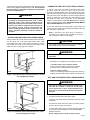
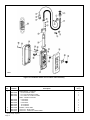
2. Determine collector arrangement on trolley before starting
assembly (i.e., whether all on one side or on two sides.)
12207A
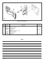
3. Assemble collector bracket with hardware provided. Secure
lightly for later adjustment.
4. Arrange collectors on pole in approximate locations and
finger tighten to pole.
5. Open cover on trolley electrical panel. Feed wire leads from
collector shoe terminals into trolley electrical panel through
box type connector in enclosure. Connect collector wire leads
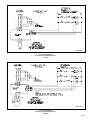
to terminal strip in accordance with appropriate wiring diagrams
furnished with trolley. Close panel cover.
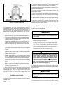
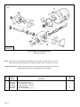
Figure 2. Proper Wheel Spacing
3. Due to manufacturing tolerances, I-beams having the same
size designations may have varying dimensions making it
impossible to prescribe the specific number of spacer washers
required between trolley side plates and suspension lug for
any given beam size. It will, therefore, be necessary to
determine the spacer washer requirement by "trial and error"
assembly.
a. First measure the exact width of bottom flange on runway
beam, and then add 1/4" to that measurement (3/8" for
curved beam). The total is the required distance between
inside faces of wheel flanges to obtain satisfactory wheel
operating clearance. See Figure 2.
b. Temporarily assemble trolley to hoist using about 3 or 4
washers at each end of suspension pins, between side
plates and suspension lug. Tighten pin nuts for accurate
check of spacing.
c. Measure distance between inside faces of wheel flanges
and compare with the total dimension obtained in paragraph
a. above.
d. Remove trolley sides and add or remove an equal number
of inside spacer washers as required to obtain proper
distance between wheels.
e. When wheel spacing is correct, remaining spacer washers
are to be installed' on outside ends of suspension pins (see
note below) and the pins then secured with lockwashers
and hex nuts. The nuts (1, Figure 2) should not be completely
tightened until after hoist and trolley are mounted on runway
beam.
Note: It is important that all spacer washers that come
with trolley be used. Install remaining spacer washers
equally on outside ends of pins.
4. Open cover on trolley electrical panel enclosure. Remove
one knockout from enclosure and thread hoist flexible cable
leads through hole. Secure box type connector with locknut
and connect leads to terminal strip in accordance with
appropriate wiring diagrams furnished with trolley.
CURRENT COLLECTORS
1. Current collectors are not standard and must be ordered as
an option. They are shipped in a separate carton and must be
installed in field.
Page 2
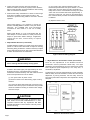
6. If trolley is equipped with a mainline disconnect panel and/
or fuse panel, connect the collector wire leads per "Fuse and
Mainline Disconnect Panels" section.
INSTALLING TROLLEY AND HOIST
1. Hoist and trolley combination may be installed on runway
beam by either of two methods.
WARNING
Be certain that electrical power supply to runway
current conductors (if used) is "off" and locked in the
open position.
a. If one end of beam is open or exposed, trolley may be
installed by sliding it onto beam.
b. If trolley cannot be slid over end of beam, remove hex
nuts (1, Figure 2), Iockwashers and outer spacer washers
from pins on one side of trolley. Spread or remove one side
plate to facilitate positioning trolley over bottom flange of
beam. Reinstall, side plate, outer spacer washers,
lockwashers and hex nuts on suspension pins.
WARNING
After trolley has been Installed on beam, make sure
suitable stop(s) is secured on open ended beams to
prevent trolley from rolling off the beam. (Stops
should contact trolley side plates, not wheels.) Make
certain that all spacer washers and lockwashers are
in place on suspension pins and that hex nuts are
tight. Recheck clearance dimension between wheel
flanges and beam flanges (Figure 2).
2. Engage slide collector shoes with runway conductor bars
and make final adjustment to pole bracket and collector spacing.
Tighten securely.
CAUTION
Power supply must be same voltage, phase and
frequency as specified on hoist and trolley motor
nameplates.
3. Follow National, State and Local electrical codes when
providing electrical service to hoist and trolley. Make electrical