1
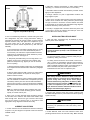
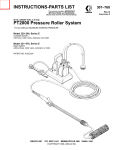
Instructions and Parts List Motor Driven Trolleys 1/4 - 7½ Ton Rated Loads GENERAL These Motor Driven Trolleys are designed for use on BUDGIT coil chain electric hoists. They attach directly to a suspension bracket or mounting lug at top of hoist. Special field conversion kits (see below) are available to accommodate use of these trolleys on existing hook type or lug mounted, push button electric hoists to convert them to motor driven suspension. Specifications herein subject to change without notice. WARNING This equipment is not suitable or designed to be used in conjunction with lifting or lowering persons. A standard 3 ton Motor Driven Trolley is illustrated in Figure 1. The push button station and cable assembly and optional items such as fuse kit, mainline contactor or ballast resistors will be mounted on the trolley and completely wired. Current collector assemblies, when ordered, will be shipped loose. Assembly of your new trolley to your electric hoist and installation of the complete unit on its runway beam can be accomplished with a minimum of effort by following the instructions given below. WARNING Since rigid mounting does not allow hoist to rotate with pull of load, rigid mounted motor driven trolleys must not be used with hoists having roller type load chain. BUDGIT HOIST FIELD CONVERSION KITS Catalog No. Description 901821 901822 901823 905421 905422 905424 Electrical Adaptor Kit - 115/1/60 A.C. Electrical Adaptor Kit - 230/1/60 A.C. Electrical Adaptor Kit - 208,230/460, 575/3/60 A.C. Lug Suspension Kit - 1/4 to 1 Ton Lug Suspension Kit - 2 Ton Lug Suspension Kit - 3 Ton Above electrical adaptor kits are used for changeover of hoist electrical system to tie-in with trolley electrical system. Hoist power cable and push button control cable are replaced by a 6 or 7 conductor cable assembly (depending on power supply) which connects into terminal strip in trolley control panel. Above lug suspension kits contain a suspension lug assembly which is installed in place of the hoist upper hook. Instructions for installing these kits are not included in this booklet. They are furnished in each kit. ASSEMBLY OF TROLLEY TO HOIST Note: If trolley is to be used on an existing BUDGIT hoist, the necessary hoist conversion kits should be first installed following instructions furnished with kit. Place hoist on workbench, suspension lug facing up, and proceed as follows: 1. On BUDGIT hoists, determine whether hoist is to be suspended with frame parallel to runway I-beam or cross mounted (90° to beam), then make certain that lug on hoist is properly oriented and istalled before any attachment to trolley. Trolleys for hoists through 1 ton may be parallel mounted and should have the electrical enclosure opposite the tail end of the load chain or chain container. The 2 through 3 ton BUDGIT hoists are cross mounted so that the multiple reeving is parallel to the beam and the trolley electrical enclosure should be on the same side as the hoist electrical enclosure. 12681 Figure 1. Standard Trolley February, 2004 THE INFORMATION CONTAINED IN THIS MANUAL IS FOR INFORMATIONAL PURPOSES ONLY AND BUDGIT DOES NOT WARRANT OR OTHERWISE GUARANTEE (IMPLIEDLY OR EXPRESSLY) ANYTHING OTHER THAN THE COMPONENTS THAT BUDGIT MANUFACTURES AND ASSUMES NO LEGAL RESPONSIBILITY (INCLUDING BUT NOT LIMITED TO CONSEQUENTIAL DAMAGES) FOR INFORMATION CONTAINED IN THIS MANUAL. 2. Determine proper spacing for trolley side plates so that adequate wheel clearance (approximately 1/8") is provided on both sides of I-beam, between inside faces of wheel flanges and edges of bottom beam flange. Proper spacing is obtained by varying the number of spacer washers (furnished with trolley) installed on suspension cross pins between suspension lug and trolley side plates (Figure 2). COPYRIGHT 2004, YaleLift-Tech, division of Columbus McKinnon Corporation Part No. 113534-98 2. Determine collector arrangement on trolley before starting assembly (i.e., whether all on one side or on two sides.) 12207A 3. Assemble collector bracket with hardware provided. Secure lightly for later adjustment. 4. Arrange collectors on pole in approximate locations and finger tighten to pole. 5. Open cover on trolley electrical panel. Feed wire leads from collector shoe terminals into trolley electrical panel through box type connector in enclosure. Connect collector wire leads to terminal strip in accordance with appropriate wiring diagrams furnished with trolley. Close panel cover. Figure 2. Proper Wheel Spacing 3. Due to manufacturing tolerances, I-beams having the same size designations may have varying dimensions making it impossible to prescribe the specific number of spacer washers required between trolley side plates and suspension lug for any given beam size. It will, therefore, be necessary to determine the spacer washer requirement by "trial and error" assembly. a. First measure the exact width of bottom flange on runway beam, and then add 1/4" to that measurement (3/8" for curved beam). The total is the required distance between inside faces of wheel flanges to obtain satisfactory wheel operating clearance. See Figure 2. b. Temporarily assemble trolley to hoist using about 3 or 4 washers at each end of suspension pins, between side plates and suspension lug. Tighten pin nuts for accurate check of spacing. c. Measure distance between inside faces of wheel flanges and compare with the total dimension obtained in paragraph a. above. d. Remove trolley sides and add or remove an equal number of inside spacer washers as required to obtain proper distance between wheels. e. When wheel spacing is correct, remaining spacer washers are to be installed' on outside ends of suspension pins (see note below) and the pins then secured with lockwashers and hex nuts. The nuts (1, Figure 2) should not be completely tightened until after hoist and trolley are mounted on runway beam. Note: It is important that all spacer washers that come with trolley be used. Install remaining spacer washers equally on outside ends of pins. 4. Open cover on trolley electrical panel enclosure. Remove one knockout from enclosure and thread hoist flexible cable leads through hole. Secure box type connector with locknut and connect leads to terminal strip in accordance with appropriate wiring diagrams furnished with trolley. CURRENT COLLECTORS 1. Current collectors are not standard and must be ordered as an option. They are shipped in a separate carton and must be installed in field. Page 2 6. If trolley is equipped with a mainline disconnect panel and/ or fuse panel, connect the collector wire leads per "Fuse and Mainline Disconnect Panels" section. INSTALLING TROLLEY AND HOIST 1. Hoist and trolley combination may be installed on runway beam by either of two methods. WARNING Be certain that electrical power supply to runway current conductors (if used) is "off" and locked in the open position. a. If one end of beam is open or exposed, trolley may be installed by sliding it onto beam. b. If trolley cannot be slid over end of beam, remove hex nuts (1, Figure 2), Iockwashers and outer spacer washers from pins on one side of trolley. Spread or remove one side plate to facilitate positioning trolley over bottom flange of beam. Reinstall, side plate, outer spacer washers, lockwashers and hex nuts on suspension pins. WARNING After trolley has been Installed on beam, make sure suitable stop(s) is secured on open ended beams to prevent trolley from rolling off the beam. (Stops should contact trolley side plates, not wheels.) Make certain that all spacer washers and lockwashers are in place on suspension pins and that hex nuts are tight. Recheck clearance dimension between wheel flanges and beam flanges (Figure 2). 2. Engage slide collector shoes with runway conductor bars and make final adjustment to pole bracket and collector spacing. Tighten securely. CAUTION Power supply must be same voltage, phase and frequency as specified on hoist and trolley motor nameplates. 3. Follow National, State and Local electrical codes when providing electrical service to hoist and trolley. Make electrical connections using the wiring diagrams furnished with the trolley and the wiring diagram furnished with the hoist. Do not attempt to operate trolley or hoist before completing "Pre-Operation Checks and Adjustments." WARNING This equipment must be effectively grounded according to the National Electrical Code, or other applicable codes. If the grounding method used is through the trolley wheels, then each section of track must be grounded by metal-to-metal connection to the building ground. Certain environments may prevent proper grounding by this means and in this case a separate grounding conductor should be provided. ATTACH PUSH BUTTON STATION STRAIN CABLE Trolleys ordered for use with hoists are shipped from the factory with the upper end of the push button station strain cable unconnected. If this is the case, it will be necessary to remove rope thimble from loose end of strain cable and attach strain cable as shown in either Figure 3 or Figure 4. CONNECTING TROLLEY TO ELECTRICAL SERVICE 1. Follow Local, State and National Electric Codes when providing electrical service to hoist. Connect wires in accordance with appropriate trolley wiring diagram. Be certain that the electrical power supply is the same as specified on trolley and hoist motor data plates. On dual voltage hoists and trolleys be certain that connections are made inside the hoist and inside the trolley motor conduit box for the appropriate voltage. On three phase models DO NOT attempt to operate trolley or hoist before completing TESTS AND ADJUSTMENTS FOR 3 PHASE MODELS which follows. 2. Common methods of connecting trolley to power supply are current collectors, previously described and flexible cable (tag line, festooned or cable reel). Note: A grounding type male plug or permanent connection in an outlet box may be used for wiring tag line or festooned cable to power supply. CAUTION Power supply must be same voltage, frequency and phase as specified on hoist and trolley nameplates. WARNING All equipment must be effectively grounded electrically. Grounding is accomplished in the following manner: (1) Flexible cable or four collector system. Connect green identified ground wire to separate grounding screw in trolley electrical enclosure. 12676 (2) Three collector system. Trolley is considered grounded through trolley wheels to properly grounded track sections. (Ref. N.E.C. Article 610). Figure 3. Push Button Strain Cable Attachment to 1/4 thru 2 ton Budgit Hoist Trolleys TEST AND ADJUSTMENTS FOR 3 PHASE MODELS WARNING Three phase hoists must be properly phased each time they are installed or moved to a new power source. Unless this is done, serious damage to the hoist can occur with resulting hazard to the operator and load. 1. To properly phase hoists follow these steps. a. Operate "UP" button briefly to determine direction of load hook travel. b. If load hook raises when "UP" button is pressed, phase is correct and hoist may be operated. 12678 Figure 4. Push Button Strain Cable Attachment to 3 thru 7-1/2 ton Budgit Hoist Trolleys c. If load hook lowers, hoist is "Reverse Phased" and must be corrected by interchanging any two leads at power source connection. Do not change internal wiring of hoist or trolley. Page 3 2. Check hoist upper and lower limit stop operation to determine if limit stop functions properly in both directions. Refer to hoist "Operation and Service Manual" under "Testing Hoist" for method to be followed. 3. Position hoist-trolley combination on I-beam so that enough clear track is available to allow travel of trolley in two directions to permit checking "RIGHT" and "LEFT" traverse operation. (4) Turn power "ON" and with maximum load to be traversed suspended from hoist, press "RIGHT" or "LEFT" trolley button and note speed of trolley acceleration. If trolley does not move or accelerates too slowly, turn power "OFF" and move all three slide bands approximately 1" away from jumper end. Turn power on and repeat above test. Continue above procedure until desired acceleration is obtained. (5) Replace resistor cover. Note Three Phase Motors: If it is desired to reverse the direction of trolley travel in relation to the push button markings, turn POWER OFF and interchange connections of motor leads "T-1" and "T-2" at trolley motor. Single Phase Motors: It is not recommended that the user attempt to reverse direction of trolley travel with respect to push button station markings. If application requires this be done, contact factory for special instructions. 4. Adjust Ballast Resistors (if furnished). a. Ballast resistors installed on 3 phase motor driven trolleys provide a "cushion-start" effect which is helpful in reducing load swing during acceleration. It will be necessary to adjust resistor slide bands with hoist under load as directed below to obtain the desired rate of acceleration. 12677 Figure 6. Resistor Wiring Diagram WARNING Ballast resistors are neither suitable nor intended for use in reducing maximum trolley running speed. b. Resistor slide bands (taps) are approximately set when shipped from factory. Field adjustments for desired acceleration should be made by user with maximum load to be moved suspended from hoist as follows: (1) Turn power "OFF" at power source. (2) Remove resistor cover. Discard any paper covering resistors. 5. Adjust Electronic Acceleration Control (if furnished). There are two adjustments on the BUDGIT Electronic Acceleration Control (sometimes called EAC). The upper adjustment (Torque Adjustment) is for the initial torque and the lower adjustment (Time Adjustment) is the ramp time, or acceleration, adjustment. To adjust the unit, turn both adjustments fully counter clockwise. With the trolley and hoist unloaded, increase the initial Torque Adjustment, by turning clockwise, until the trolley moves as soon as the push button is depressed. This adjustment is usually adequate. (3) Loosen the three slide bands and move them to the extreme end to which jumpers are attached. This provides maximum resistance resulting in reduced motor voltage and motor torque. CAUTION To prevent damage to trolley motor, be certain the three slide bands are IN-LINE HORIZONTALLY on their respective resistors after any adjustment. DO NOT ROTATE slide bands on their resistors. This may cause electrical shorting. Electronic Acceleration Control Page 4 227728 Sht.1 Connection Diagram Electronic Acceleration Control 1 Speed 228107 Sht.1 Connection Diagram Electronic Acceleration Control 2 Speed Page 5 Should the trolley not start promptly at normal loads, adjust the Time Adjustment clockwise until it operated in a satisfactory manner. Torque Adjustment may also be adjusted according to insure proper operation. To adjust the unit prior to installation, when the trolley is not installed, turn the Torque and Time Adjustments fully counterclockwise. Turn the Torque Adjustment clockwise until the motor just starts when the push button is depressed and then turn the additional 5 degrees. TESTING SINGLE PHASE TROLLEY MOTOR OPERATION To check operation of starting winding centrifugal switch, connect ammeter (minimum 10 ampere) to MOTOR lead "T5". Ampere reading must drop to zero in approximately one second when operating trolley in both directions of travel. If ampere reading does not drop to zero, interchange motor lead "T6" with "T7" and recheck. If ampere reading still does not return to zero after above checks have been made, the motor centrifugal switch is defective and must be replaced to avoid motor burn out. FUSE AND MAINLINE DISCONNECT PANELS Mainline disconnect panels and/or hoist-trolley fuse panels are provided as options on motor driven trolleys to assist users in complying with OSHA codes. When ordered with trolley, they will be completely installed on trolley and wired into trolley electrical system. Electrical service is to be connected to trolleys equipped with fuse panels and/or mainline disconnect panels as follows: 1. Fuse Panels Only. Connect leads from power supply to hoist fuse terminals "L-1", "L-2" and "L-3" (3-phase) under hoist fuses. See trolley wiring diagram. 2. Mainline disconnect (furnished with fuse panels only). Connect power supply leads "ML-1", "ML-2" and "ML-3" (3phase) to the upper power terminals of mainline contactor. Refer to trolley wiring diagram. CAUTION Power supply must be same voltage, frequency and phase as specified on hoist and trolley nameplates. MAINTENANCE AND LUBRICATION 1. Budgit Motor Driven Trolleys are built to give long service, but should be inspected periodically for evidence of damage or wear, particularly when subjected to unusually severe operating conditions. 2. Lubrication requirements: a. Wheel bearings are permanently lubricated and require no additional lubricant. b. Drive wheel gears are to be lubricated with an open type gear grease which is heavy, plastic, extreme pressure and tacky; such as MOBILTAC 275 NC or equal. c. The right angle worm gear reducer oil is a synthetic lubricant with excellent wear protection capability and long life. This oil does not require changing. When replacing oil due to repairs, use MOBIL SHC 634 or equal. REPLACEMENT PARTS The following parts lists and illustrations cover standard model Budgit motor driven trolleys. Typical units are used as the basis for the exploded parts illustrations; therefore, certain variations may occur from the parts information given. For this reason always give the catalog number, model number, motor horsepower, voltage, phase and frequency of trolley when ordering replacement parts. For motors, gearboxes and electrical components, give complete nameplate data. Pins referred to in some column headings are trolley suspension pins. The factory recommends complete replacement of the motor or gearbox. Gearbox service is available, however, from your local authorized Budgit repair station. Use only factory provided replacement parts. Parts may look alike but parts are made of specific materials and processes to achieve specific properties. The numbers assigned to the parts of our various assemblies In our parts lists are not the part numbers used In manufacturing the part. They are identification numbers, that when given with the trolley serial number, permit us to identify, select or manufacture, and ship the correct part needed for any trolley. Supply Complete numbers from the identification plate of the gearbox that match the numbers (including digits - where x's appear) In the lower right hand comer of the parts illustration for the motor and gearbox assemblies. INDEX OF PARTS ILLUSTRATIONS Title Trolley Frame and Wheels (4" 0 Wheels - 3-1/8" & 5" c/c Pins) .................................................................... Trolley Frame and Wheels (4" 0 Wheels - 6" c/c Pins) .................................................................................. Trolley Frame and Wheels (6-1/2"ø Wheels - 6" c/c Pins) ............................................................................. Motor and Gearbox Assembly (3-1/8" & 5" c/c Pins) ..................................................................................... Motor and Gearbox Assembly (6" c/c Pins) .................................................................................................... Electrical Enclosure Mountings ....................................................................................................................... Electrical Enclosures ....................................................................................................................................... Push Button Station and Conductor Cable Assembly .................................................................................... Current Collectors ............................................................................................................................................ Ballast Resistors .............................................................................................................................................. Electronic Acceleration Control ....................................................................................................................... Page 6 Figure No. Page No. 7 8 8A 9 10 11 12 13 14 - 7 8 9 10 11 12 14 16 18 19 19 12667 Figure 7. Trolley Frame and Wheels - One Motor (4"ø Wheels - 3-1/8" & 5" c/c Pins) 3-1/8" c/c Pins Ref. No. 1 2 3 4 5 6 7 8 9 10 11 12 13 14 15 16 17 18 Description Plate Assembly - Side For 3" to 5" Flange Widths and Patented Track For 5-1/8" to 7-1/4" Flange Widths For 7-1/2" to 9-1/8" Flange Widths For 3-5/8" to 6" Flange Widths and Patented Track For 6-1/4" to 8-5/8" Flange Widths For 8-7/8" to 11-1/4" Flange Widths Shaft - Wheel Bearing - Ball Ring - Retaining Wheel - Plain (Except Patented Track) For Patented Track Only Wheel - Geared (Except Patented Track) For Patented Track Only Ring - Retaining Pinion - Motor Ring - Retaining Key- Motor Pinion Screw- Hex Cap Nut- Serf-locking Lockwasher Nut- Hex Jam Nut - Hex Jam Lockwasher Washer - Spacer Pin - Suspension For 3" to 5" Flange Widths and Patented Track For 5-1/8" to 7-1/4" Flange Widths For 7-1/2" to 9-1/8" Flange Widths For 3-5/8" to 6" Flange Widths and Patented Track For 6-1/4" to 8-5/8" Flange Widths For 8-7/8" to 11-1/4" Flange Widths 5" c/c Pins Part Number Qty. Req'd. Part Number Qty. Req'd. BET-2700 BET-2701 BET-2702 – – – BET-2706 BET-2707 BET-2708 BET-2709 BET-2710 BET-2711 BET-2712 BET-2713 BET-2714 BET-2716 BET-2717 BET-2718 BET-2719 BET-2720 BET-2721 BET-2722 BET-2723 BET-2724 2 2 2 – – – 4 8 4 2 2 2 2 4 1 1 1 8 8 4 4 4 4 56 – – – BET-2703 BET-2704 BET-2705 BET-2706 BET-2707 BET-2708 BET-2709 BET-2710 BET-2711 BET-2712 BET-2713 BET-2715 BET-2716 BET-2717 BET-2718 BET-2719 BET-2720 BET-2721 BET-2721 BET-2720 BET-2725 – – – 2 2 2 4 8 4 2 2 2 2 4 1 1 1 8 8 4 4 4 4 36 BET-2726 BET-2727 BET-2728 – – – 2 2 2 – – – – – – BET-2729 BET-2730 BET-2731 – – – 2 2 2 Page 7 12668 Figure 8. Trolley Frame and Wheels (4"ø Wheels & 6" c/c Pins) Ref. No. Part Number 1 2 3 4 5 6 7 8 9 10 11 12 13 14 15 BET-2800 BET-2801 BET-2802 BET-2803 BET-2804 BET-2805 BET-2806 BET-2807 BET-2808 BET-2809 BET-2810 BET-2811 BET-2812 BET-2813 BET-2814 BET-2815 BET-2816 BET-2817 BET-2818 BET-2819 BET-2820 Page 8 Description Plate Assembly - Side For 4" to 6-1/4" Flange Widths and Patented Track For 6-3/8" to 8-5/8" Flange Widths For 8-3/4" to 11" Flange Widths Bearing - Ball Ring - Retaining Wheel - Plain (Except Patented Track) For Patented Track Only Wheel - Geared (Except Patented Track) For Patented Track Only Ring - Retaining Pinion - Motor Key - Motor Pinion Ring - Retaining Screw - Hex Cap Nut - Self-locking Nut - Hex Jam Lockwasher Washer - Spacer Pin - Suspension For 4" to 6-1/4" Flange Widths and Patented Track For 6-3/8" to 8-5/8" Flange Widths For 8-3/4" to 11" Flange Widths Qty. Req’d. 2 2 2 8 4 2 2 2 2 4 1 1 1 4 4 4 4 40 2 2 2 12670 Figure 8A. Trolley Frame and Wheels - One Motor (6½" ø Wheels - 6" c/c Pins) Ref. No. 1 2 3 4 5 6 7 8 9 10 11 12 13 14 15 Description Plate Assembly - Side For 4" to 6-1/4" Flange Widths and Patented Track For 6-3/8" to 8-5/8" Flange Widths For 8-3/4" to 11" Flange Widths Bearing - Ball Ring - Retaining Wheel - Plain (Except Patented Track) For Patented Track Only Wheel - Geared (Except Patented Track) For Patented Track Only Ring - Retaining Pinion - Motor Key - Motor Pinion Ring - Retaining Screw- Hex Cap Nut - Self-locking Nut - Hex Jam Lockwasher Washer-Spacer Pin - Suspension For 4" to 6-1/4" Flange Widths and Patented Track For 6-3/8" to 8-5/8" Flange Widths For 8-3/4" to 11" Flange Widths 1¼" ø Pins Part No. 1½" ø Pins Part No. Qty. Req'd. BET-3800 BET-3802 BET-3804 BET-3811 BET-3813 BET-3815 BET-3817 BET-3818 BET-3820 BET-3821 BET-3823 BET-3824 BET-3825 BET-3826 BET-3828 BET-3829 BET-3832 BET-3835 BET-3801 BET-3803 BET-3805 BET-3811 BET-3813 BET-3815 BET-3817 BET-3818 BET-3820 BET-3821 BET-3823 BET-3824 BET-3825 BET-3826 BET-3828 BET-3830 BET-3833 BET-3836 2 2 2 8 4 2 2 2 2 4 1 1 2 4 4 4 4 40 BET-3838 BET-3840 BET-3842 BET-3839 BET-3841 BET-3843 2 2 2 Page 9 12737 439509-xx 602005-03-E Figure 9. Motor and Gearbox Assembly (3-1/8" & 5" c/c Pins) Notice: Five types of motor and gearbox assemblies have been used for trolleys with 3-1/8" & 5" c/c. When ordering replacement gearbox for 439076-xx gearbox, order new gearbox and motor. Ordering Instructions: Furnish complete data from motor and gearbox nameplates with parts order. Replacement parts cannot be provided without this information. Ref. No. 1 2 5 6 Page 10 Part Number BET-3600 BET-3601 BET-3602 BET-3603 BET-3606 BET-3607 Description Motor and Gearbox Assembly - Complete Motor (Includes Ref. No.2) Key - Motor (1/8 x 1/8 x 3/4) Gearbox Assembly - Complete Lockwasher (3/8) Bolt - Hex Head (3/8 - 16 x 1) Qty. Req’d 1 1 1 4 4 439077-xx 10270717 12680 Figure 10. Motor and Gearbox Assembly (6" c/c Pins) Ordering Instructions: Furnish complete data from motor and gearbox nameplates with parts order. Replacement parts cannot be provided without this information. Ref. No. Part Number 1 2 BET-3000 BET-3001 BET-3002 BET-3003 5 6 BET-3007 Description Motor and Gearbox Assembly - Complete Motor (Includes Ref. No.2) Key - Motor (3/16 x 3/16 x 1-1/4) Gearbox Assembly - Complete Lockwasher (3/8) Bolt- Hex Head (3/8 - 16 x 7/8) Qty. Req’d 1 1 1 1 4 4 Page 11 12672 Figure 11. Electrical Enclosure Mountings Ref. No. Part Number 1 2 3 4 5 6 BET-3100 BET-3101 BET-3102 BET-3103 BET-3104 BET-3105 7 8 9 10 11 12 BET-3106 BET-3107 BET-3103 BET-3104 BET-3108 BET-3105 Page 12 Description For Trolleys with 3-1/8" and 5" c/c Pins: Screw - Hex Cap Nut - Self-locking Mounting Bracket - Enclosure Nut - Hex Lockwasher Bolt - Hex Head For Trolleys with 6" c/c Pins: Bolt - Hex Head Lockwasher Nut - Hex Lockwasher Mounting Bracket - Enclosure Bolt - Hex Head Qty. Req’d 4 4 1 4 4 4 4 4 4 4 1 4 Notes 12673 Figure 12. Electrical Enclosures Ref. No. Part Number 1 2 BET-3200 BET-3201 BET-3202 3 4 5 BET-3203 BET-3204 BET-3205 BET-3206 6 BET-3207 BET-3208 BET-3209 BET-3210 BET-3211 BET-3212 7 BET-3213 BET-3214 8 BET-3201 BET-3202 9 BET-3203 BET-3204 Description Standard Enclosure: Enclosure - Electrical Contactor - Accelerating (For 2 Speeds Only) 24 Volt Control 115 Volt Control Contactor - Reversing 24 Volt Control 115 Volt Control Board - Terminal Enclosure For Options:* Enclosure - Electrical Transformer 208/24 Volt 230/24 Volt or 460/24 Volt 575/24 Volt 208/115 Volt 230/115 Volt or 460/115 Volt 575/115 Volt Contactor - Mainline 24 Volt Control 115 Volt Control Contactor - Accelerating 24 Volt Control 115 Volt Control Contactor - Reversing 24 Volt Control 115 Volt Control (Continued on Next Page) Page 14 Qty. Req’d 1 1 1 1 1 1 1 1 1 1 1 1 1 1 1 1 1 1 1 Figure 12. Electrical Enclosures (Continued). Ref. No. Part Number 10 11 BET-3205 BET-3215 BET-3216 BET-3217 BET-3218 BET-3219 BET-3220 BET-3221 BET-3222 12 BET-3223 BET-3224 Description Board -Terminal Fuses 3 Amp, 250 Volt 3 Amp, 600 Volt 6 Amp, 250 Volt 6 Amp, 600 Volt 10 Amp, 250 Volt 10 Amp, 600 Volt 15 Amp, 250 Volt 15 Amp, 600 Volt Fuse Base 30 Amp, 250 Volt 30 Amp, 600 Volt Qty. Req’d 2 As As As As As As As As Req'd. Req'd. Req'd. Req'd. Req'd. Req'd. Req'd. Req'd. 2 2 * Components shown for maximum possible number of options. Any specific trolley may require only some of the shown components. Notes Page 15 12675 Figure 13. Push Button Station and Conductor Cable Assembly Ref. No. Part Number 1 BET-3300 BET-3301 BET-3302 3 4 5 BET-3303 BET-3304 BET-3305 BET-3306 BET-3307 BET-3308 BET-3309 BET-3310 Description Grip Assembly - Conductor For 6 Conductor Cable For 7 and 8 Conductor Cable For 10 and 12 Conductor Cable Cable - Flexible Conductor* 6 Conductor 7 Conductor 8 Conductor 10 Conductor 12 Conductor Thimble - Strain Cable Connector - Strain Cable Connector - Conductor to Strain Cable * Specify length required. Page 16 Qty. Req’d 1 1 1 1 1 1 1 1 2 1 1 Figure 13. Push Button Station and Conductor Cable Assembly (Continued). Ref. No. Part Number 6 BET-3311 BET-3312 BET-3313 BET-3314 BET-3315 BET-3316 BET-3317 BET-3318 BET-3319 BET-3320 9 10 11 12 13 14 15 16 17 18 19 20 21 22 23 BET-3325 ** ** ** ** ** ** ** BET-3327 BET-3328 24 25 BET-3329 BET-3330 BET-3331 BET-3332 BET-3333 BET-3334 BET-3335 Description Clamp - Conductor For 6 Conductor Cable For 7 Conductor Cable For 8 and 10 Conductor Cable For 12 Conductor Cable Cable - Strain* Sleeve - Pressure Push Button Station Assembly - 4 Buttons (Includes Ref. Nos. 9 thru 24) Push Button Station Assembly - 6 Buttons (Includes Ref. Nos. 9 thru 24) Enclosure Assembly - 4 Buttons (Includes Ref. Nos. 9 thru 21) Enclosure Assembly - 6 Buttons (Includes Ref. Nos. 9 thru 21) Clamp - Conductor Screw - Slotted Head Lockwasher Support - Strain Cable Sleeve - Conductor Nut - Hex Screw - Slotted Head Clamp - Conductor Enclosure Body Enclosure Front Enclosure Rear Screw - Slotted Head 4 Button Station 6 Button Station Lockwasher 4 Button Station 6 Button Station Block - Contact 4 Button Station 6 Button Station Push Button Assembly 4 Button Station 6 Button Station Nameplate Up Down Right Left Start Stop Operator Warning Label Qty. Req’d 1 1 1 1 1 1 1 1 1 1 1 2 2 1 1 2 2 1 1 1 1 4 6 4 6 4 6 4 6 1 1 1 1 1 1 1 * Specify length required. ** Not available separately. Order Enclosure Assembly. Notes Page 17 12674 Figure 14. Current Collectors Ref. No. Part Number 1 2 3 4 BET-3400 BET-3401 BET-3402 BET-3403 1 2 3 4 BET-3400 BET-3401 BET-3402 BET-3403 Description Collectors on One Side of Trolley Only: Bracket - Collector Bolt - Hex Head Lockwasher Collector Collectors on Both Sides of Trolley: Bracket - Collector Bolt - Hex Head Lockwasher Collector Notes Page 18 Qty. Req’d 1 2 2 As Req'd. 2 4 4 As Req'd. Ballast Resistors (Optional) No Illustration Resistor Assembly (Including Enclosure) Supply Voltage and Trolley Motor Horsepower Resistor Part Number Qty. Req'd. Part Number Qty. Req'd. 208-230 Volt 1/6 H P 1/4 H P 1/2 HP BET-3500 BET-3502 BET-3504 1 1 1 BET-3501 BET-3503 BET-3505 3 3 3 460 Volt 1/6 HP 1/4 H P 1/2 HP BET-3506 BET-3508 BET-3500 1 1 1 BET-3507 BET-3509 BET-3501 3 3 3 575 Volt 1/6 and 1/4 HP 1/2 HP BET-3506 BET-3508 1 1 BET-3507 BET-3509 3 3 Part Number BET-3700 BET-3701 BET-3702 BET-3703 Description 208-460V Power, 115V AC Control, 1 208-460V Power, 24V AC Control, 1 208-460V Power, 115V AC Control, 2 208-460V Power, 24V AC Control, 2 Speed Speed Speed Speed Qty. Req’d 1 1 1 1 Notes Page 19 Recommended Spare Parts for Your Budgit Motor Driven Trolley Certain parts of your trolley will, in time, require replacement under normal wear conditions. It is suggested that the following parts be purchased for your trolley as spares for future use. Motor Pinion One Set of Wheel Bearings One Set of Wheels One Reversing Contactor One Set of Fuses (If Required) Note: When ordering parts always furnish Model and Catalog Number and Motor Nameplate Data of trolley on which the parts are to be used. Parts for your trolley are available from your local authorized Budgit repair station. For the location of your nearest repair station, write: IN USA YaleLift-Tech P.O. Box 769 Muskegon, MI 49443-0769 Phone: 800 742-9269 Fax: 800 742-9270 WARRANTY WARRANTY AND LIMITATION OF REMEDY AND LIABILITY A. Seller warrants that its products and parts, when shipped, and its work (including installation, construction and start-up), when performed, will meet applicable specifications, will be of good quality and will be free from defects in material and workmanship. All claims for defective products or parts under this warranty must be made in writing immediately upon discovery and in any event, within one (1) year from shipment of the applicable item unless Seller specifically assumes installation, construction or start-up responsibility. All claims for defective products or parts when Seller specifically assumes installation, construction or start-up responsibility and all claims for defective work must be made in writing immediately upon discovery and in any event, within one (1) year from completion of the applicable work by Seller, provided; however, all claims for defective products and parts made in writing no later than eighteen (18) months after shipment. Defective items must be held for Seller’s inspection and returned to the original f.o.b. point upon request. THE ‘FOREGOING IS EXPRESSLY IN LIEU OF ALL OTHER WARRANTIES WHATSOEVER, EXPRESS, IMPLIED AND STATUTORY, INCLUDING, WITHOUT LIMITATION, THE IMPLIED WARRANTIES OF MERCHANTABILITY AND FITNESS. B. Upon Buyer’s submission of a claim as provided above and its substantiation, Seller shall at its option either (i) repair or replace its product, part or work at either the original f.o.b. point of delivery or at Seller’s authorized service station nearest Buyer or (ii) refund an equitable portion of the purchase price. C. This warranty is contingent upon Buyer’s proper maintenance and care of Seller’s products, and does not extend to normal wear and tear. Seller reserves the right to void warranty in event of Buyer’s use of inappropriate materials in the course of repair or maintenance, or if Seller’s products have been dismantled prior to submission to Seller for warranty inspection. D. The foregoing is Seller’s only obligation and Buyer’s exclusive remedy for breach of warranty and is Buyer’s exclusive remedy hereunder by way of breach of contract, tort, strict liability or otherwise. In no event shall Buyer be entitled to or Seller liable for incidental or consequential damages. Any action for breach of this agreement must be commenced within one (1) year after the cause of action has accrued.