1
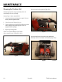
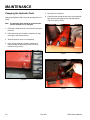
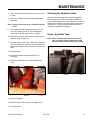
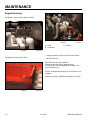
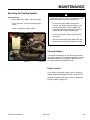
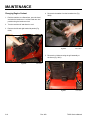
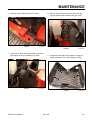
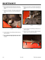
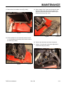
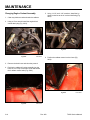
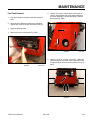
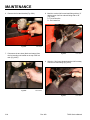
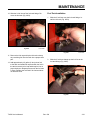
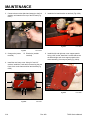
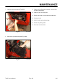
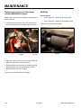
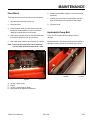
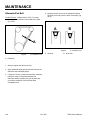
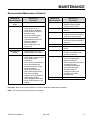
MAINTENANCE Recommended Maintenance Schedule Maintenance Service Interval After the first 8 hrs Daily 25 hrs After the first 50 hrs 100 hrs Maintenance Procedure Maintenance Service Interval • Change hydraulic filter • • • • Grease the traction unit Check engine oil level Check for loose fasteners Clean/inspect the tracks for damage or wear • Check the cooling system • Drain water and other contaminants from the fuel filter/water separator • Clean the radiator • Remove debris from the traction unit 200 hrs • Change hydraulic filter • Replace primary air filter • Change engine oil filter 250 hrs • Check & grease the road wheels 400 hrs • Inspect fuel lines for leaks • Change hydraulic oil and filter • Change the hydraulic fluid 500 hrs • Replace the alternator/fan belt (refer to the engine operator’s manual) 600 hrs • Replace the safety air filter 1,500 hrs • Check hydraulic oil Yearly • Change engine oil & filter • Check & adjust track tension • Change engine oil • Check battery electrolyte level • Check battery cable connections • Check cooling system hoses • Check the alternator/fan belt tension (refer to engine operator’s manual) • Check hydraulic lines for leaks, loose fittings, kinked lines, loose mounting supports, wear, weather and chemical deterioration • Check & adjust track tension • Check for dirt build-up in the chassis Maintenance Procedure • Replace all moving hydraulic hoses • Change the engine coolant • Check the condition of the hydraulic pump belt Yearly Storage • • • • • Every 2 Years • Drain & clean the fuel tank Check for loose fasteners Touch up chipped paint Adjust track tension Check tracks and road wheels Complete all yearly maintenance procedures specified in the engine operator’s manual • Charge the battery and disconnect the cables (storage only) Important: Refer to your engine operator’s manual for additional maintenance procedures. Note: The hourmeter does not have service indicators. TX525 Service Manual Rev. 000 3-1 MAINTENANCE Greasing the Traction Unit (4) are located on the right side (Fig. 0002). Grease all pivot joints every 8 operating hours and immediately after every washing. Grease Type: Lithium based NLGI2 1. Lower the loader arm and stop the engine. Remove the key from the ignition switch. 2. Clean the grease fittings with a rag. 3. Connect grease gun to each fitting and pump grease into the fittings until grease begins to ooze out (approximately 3 pumps). 4. Wipe any excess grease. There are 12 grease fittings on the TX525: (4) are located on the left side (Fig. 0001). Fig 0002 PICT-8729a (4) are located in the front on the quick attachment assembly and the front loader arm assembly (Fig. 0003). Fig 0001 PICT-8726a 3-2 Rev. 000 Fig 0003 PICT-8730 TX525 Service Manual MAINTENANCE Maintaining the Road Wheels 4. Ensure that the road wheel turns smoothly on the bearing. If it does not turn smoothly or spin freely, replace the bearing; refer to “Road Wheel Rebuild” on page 7-79. 1. If the inner wheels or the complete tray of wheels needs maintenance, remove the tracks. Refer to “Wide Track Removal” on page 7-68 or “Narrow Track Removal” on page 7-72. 5. Check the grease under the cap and around the gasket. If it is dirty, gritty, or depleted, clean out all of the grease, replace the gasket, and fill the head of the cap with new grease (Fig. 0006). 2. Remove the snap ring from a road wheel (Fig. 0004). Note: It is not always necessary to remove the track guide when replacing any of the road wheel bearings. They can also be removed by raising the unit off the ground. For safety reasons, make sure the frame of the unit is supported. Fig 0004 DSC-0821a 3. Remove the wheel bearing cap with seal (Fig. 0005). TX525 Service Manual Fig 0005 Fig 0006 DSC-0835a DSC-0822 Rev. 000 3-3 MAINTENANCE Hydraulic Reservoir Tank 6. Remove the cap from the filler neck and check the fluid level on the dipstick (Fig. 0008). Location The hydraulic reservoir tank is located in the front of the TX525 unit. Hydraulic Tank Capacity: 10.5 gallons (39.7 liters) Type of Oil to Use: 10w-30 or 15w-40 detergent, diesel engine oil (API Service CH-4 or higher). Checking the Hydraulic Fluid Check the hydraulic fluid level daily before the engine is first started and after every 25 operating hours. 1. Remove the attachment, if one is installed. 2. Park the traction unit on a level surface, open the hood, raise the loader arm, install cylinder lock and fully retract the tilt cylinder. 3. Stop the engine, remove the key, and and allow the engine to cool. Fig 0008 PICT-8738 7. The fluid level should be between the marks on the dipstick. If the level is low, add enough fluid to raise it to the proper level. 8. Install the cap on the filler neck. 4. Remove the LH side grill. 9. Install the RH side grill. 5. Clean the area around the filler neck of the hydraulic tank (Fig. 0007). 10. Start the unit, remove the cylinder lock and lower the loader arms. 11. Close the hood. 3-4 Fig 0007 PICT-8731 Rev. 000 TX525 Service Manual MAINTENANCE Replacing the Hydraulic Filter 6. Wipe the surface of the filter adapter gasket area clean. Change the hydraulic filter: 7. Pre-fill the hydraulic oil filter with oil and apply a thin coat of oil to the rubber gasket on the replacement filter. • After the first 8 operating hours. • After every 200 operating hours. 1. Position the traction unit on a level surface. 2. Lower the loader arm, stop the engine, and remove the key. 3. Remove the rear access cover. 8. Install the replacement hydraulic filter onto the filter adapter. Hand tighten it clockwise until the rubber gasket contacts the filter adapter, then tighten the filter an additional 3/4 turn. 9. Remove absorbant towels and wipe up any spilled fluid. 10. Open the hood. Start the engine, raise and lower the loader arm. IMPORTANT: Do not substitute an automotive oil filter or severe hydraulic system damage may result. 11. Raise the loader arm and install cylinder lock. 4. Place absorbant towels under the filter. 12. Stop the engine, remove the LH side grill, check the fluid level in the hydraulic tank (refer to “Checking the Hydraulic Fluid” on page 3-4) and add fluid to raise the level to the mark on the dipstick. Do not over fill the tank. 5. Remove the old filter (Fig. 0009). 13. Install LH side grill. 14. Install the rear access cover. 15. Remove cylinder lock and lower the loader arms. 16. Close the hood. Note: Dispose of used oil and filters at a certified recycling center. TX525 Service Manual Fig 0009 Belt 013 Rev. 000 3-5 MAINTENANCE Changing the Hydraulic Fluid 5. Remove the LH side grill. Change the hydraulic fluid every 400 operating hours or yearly. 6. Clean the area around the filler neck of the hydraulic tank. Remove the hydraulic tank cap and dipstick (Fig. 0011 and Fig. 0012). Note: The hydraulic filter should be replaced whenever the hydraulic oil is changed. 1. Position the traction unit on a level surface and open the hood. 2. Raise the loader arm, install the cylinder lock, stop the engine, and remove the key. 3. Allow the traction unit to cool completely. 4. Place a large drain pan (capable of holding 15 gallons) under the drain plug on the front of the traction unit (Fig. 0010). 3-6 Fig 0010 Fig 0011 PICT-8731 Fig 0012 PICT-8738 PICT-8725 Rev. 000 TX525 Service Manual MAINTENANCE 7. Remove the drain plug and allow the oil to drain into the pan. 8. When oil is finished draining, install and tighten the drain plug. Note: Dispose of the used oil at a certified recycling center. 9. Fill the hydraulic tank with approximately 10.5 gallons (39.7 liters) of 10w-30 or 15w-40 detergent, diesel engine oil (API Service CH-4 or higher). Checking the Hydraulic Lines After every 100 operating hours, check the hydraulic lines and hoses for leaks, loose fittings, kinked lines, loose mounting supports, wear, and weather or chemical deterioration. Replace all moving hydraulic hoses every 1500 hours or 2 years, whichever comes first. Make necessary repairs before operating. Vents - Hydraulic Tank 10. Replace the hydraulic filter. Refer to “Replacing the Hydraulic Filter” on page 3-5. 11. Start the engine, remove the cylinder lock, raise and lower the loader arm, then drive the unit forward and backward to purge air from the system and check for leaks. Note: When checking hydraulic lines and hoses, also check the hydraulic tank vent to make sure it is clean and free of debris (Fig. 0014). 12. Stop the engine. 13. Check the hydraulic fluid level and top it off if necessary. 14. Replace the hydraulic tank cap and dipstick (Fig. 0013). Fig 0013 Fig 0014 PICT-8740 PICT-8731 15. Install LH side grill. 16. Remove cylinder lock and lower the loader arms. 17. Close the hood. TX525 Service Manual Rev. 000 3-7 MAINTENANCE Engine Servicing B Oil Dipstick - check oil level daily (Fig. 0015). A C A. Oil fill B. Oil dipstick Fig 0015 Fig 0017 PICT-8744 C. Oil filter PICT-8741 • Change oil after the first 50 hrs then every 100 hrs1, 2 Oil Drain (Fig. 0016 and Fig. 0017) • Oil Filter 200 hrs1, 3 More often in dusty, dirty conditions. Change oil after the first 50 operating hours. 3 For severe duty or rental applications, change every 3 100 operating hours. 1 2 Oil type: Detergent diesel engine oil (API Service CH-4 or higher) Crankcase capacity: With filter 0.98 gallons (3.7 liters) 3-8 Fig 0016 PICT-8914 Rev. 000 TX525 Service Manual MAINTENANCE Servicing the Cooling System ! Service Interval: • Before each use or daily - Clean the radiator. If the engine has been running, the pressurized, hot coolant can escape and cause severe burns. • Every 100 hours - Check the cooling system hoses. • Do not remove the radiator cap when the engine is hot. Always allow the engine to cool at least 15 minutes or until the radiator cap is cool enough to touch without burning your hand before removing the radiator cap. • Yearly - Change the engine coolant. • Do not touch radiator and surrounding parts that are hot. • Use a rag when opening the radiator cap, and open the cap slowly to allow steam to escape. Cleaning Radiator Fig 0018 PICT-8749 The engine fan draws the air from the engine compart ment and pushes the air through that hydraulic oil cooler and radiator. Remove any build up of debris on the oil cooler and radiator with compressed air. Engine Coolant If you need to add engine coolant, refer to “Checking, Adding & Bleeding the Engine Coolant” on page 4-138. Change the engine coolant yearly. Refer to “Changing Engine Coolant” on page 3-10. TX525 Service Manual Rev. 000 3-9 MAINTENANCE Changing Engine Coolant 4. Remove the breather from the breather tube (Fig. 0020). 1. Park the machine on a flat surface, open the hood and raise the loader arm. Lock the loader arm into position using the loader arm lock. 2. Turn the machine off and allow it to cool. 3. Remove the left and right hand side panels (Fig. 0019). Fig 0020 PICT-4946a 5. Remove the 4 bolts securing the grill assembly to the frame (Fig. 0021). Fig 0019 PICT-4945 3-10 Rev. 000 Fig 0021 PICT-4953 TX525 Service Manual MAINTENANCE 6. Slide the grill assembly forward (Fig. 0022). Fig 0022 8. Remove the grill assembly taking care not to damage the hydraulic tank breather hose (Fig. 0024). PICT-4955 7. Remove the 2 bolts and nuts securing the overflow tank bracket to the grill assembly (Fig. 0023). TX525 Service Manual Fig 0023 PICT-4959 Fig 0024 PICT-4961 9. Inspect the foam seals on the inside of the grill assembly. Replace if worn or damaged (Fig. 0025). Rev. 000 Fig 0025 PICT-5138a 3-11 MAINTENANCE 10. Place an absorbent towel under the oil cooler inlet fitting located on the lower left hand corner of the oil cooler. 14. Using a 1-1/16” and a 1-1/8” wrench, remove the oil cooler outlet line from the oil cooler outlet fitting (Fig. 0027). 11. Using a 1-1/16” and a 1-1/8” wrench, remove the oil cooler inlet line from the oil cooler inlet fitting (Fig. 0026). Fig 0026 PICT-4965 12. Cap the hydraulic line and fitting so debris does not enter the system. Fig 0027 PICT-4968a 15. Cap the hydraulic line and fitting so debris does not enter the system. 16. Using a 1/2” socket, remove the 3 bolts securing the radiator mount to the frame (Fig. 0028). 13. Place an absorbent towel under the oil cooler outlet fitting located on the upper right hand corner of the oil cooler. 3-12 Rev. 000 Fig 0028 PICT-4969 TX525 Service Manual MAINTENANCE 17. Remove the front radiator mount (Fig. 0029). Fig 0029 19. Slide a length of 5/16” hose onto the petcock drain. Place the other end of the hose into a drain pan. Open the petcock and remove the radiator cap to drain the anti-freeze (Fig. 0031). PICT-4971 18. Tilt the radiator/oil cooler assembly forward and lift it out of the frame so that the petcock drain is above the frame (Fig. 0030). Fig 0031 PICT-4974 20. Remove the drain hose and close the petcock. 21. Using a 17mm wrench, remove the engine block coolant drain plug (Fig. 0032). Fig 0030 PICT-4973 TX525 Service Manual Rev. 000 Fig 0032 PICT-8910 3-13 MAINTENANCE Changing Engine Coolant Assembly 5. Using 1-1/16” and 1-1/8” wrenches, install the hydraulic outlet line to the oil cooler outlet fitting (Fig. 0035). 1. Clean any debris around and under the radiator. 2. Using a 17mm wrench install the engine block coolant drain plug (Fig. 0033). Fig 0033 PICT-8910 Fig 0035 PICT-5126 6. Position the radiator mount into the frame (Fig. 0036). 3. Remove the drain hose and close the petcock. 4. Position the radiator/oil cooler assembly into the frame so it is on top of the foam seals and behind the 3 radiator mount holes (Fig. 0034). 3-14 Fig 0034 Fig 0036 PICT-5129 PICT-5122 Rev. 000 TX525 Service Manual MAINTENANCE 7. Loosely install 3 screws that will secure the radiator mount to the frame (Fig. 0037). Fig 0037 PICT-5131 8. Center the radiator and oil cooler assembly side to side in the frame so there is approximately a 1/8” space between the fan shroud and the fan. Spin the cooling fan. Ensure the fan does not come into contact with the fan shroud. Adjust the radiator side to side as necessary (Fig. 0038). 9. Without moving the position of the radiator, slide the radiator mount against the radiator and tighten the 3 radiator mount screws (Fig. 0039). TX525 Service Manual Fig 0038 PICT-5137 10. Position the grill onto the frame and route the breather tube in between the foam seals on the inner left side of the grill (Fig. 0040). Fig 0039 Fig 0040 PICT-5139 PICT-5135 Rev. 000 3-15 MAINTENANCE 11. Slide grill onto the frame so the grill base sits under the loader stops and the top of the grill sits on top of the radiator. Leave the grill in a slightly forward position. The overflow tank mounting holes should be just beyond the right hand boss on top of the radiator assembly. This will allow the overflow bottle assembly to be installed (Fig. 0041). 13. Install 2 bolts and nuts securing the overflow bottle assembly to the grill assembly (Fig. 0043). A B A Fig 0041 PICT-5141a A. Overflow tank mounting holes B. Right hand boss Fig 0043 PICT-5145 14. Slide the grill assembly back aligning the mounting holes with the holes in the frame. Loosely install 4 bolts securing the grill assembly to the frame and the 2 bolts and washers securing the grill to the radiator (Fig. 0044). 12. Position the overflow tank bracket onto the grill assembly (Fig. 0042). 3-16 Fig 0042 Fig 0044 PICT-5146 PICT-5143a Rev. 000 TX525 Service Manual MAINTENANCE 15. Using a 1/2” socket, tighten the 4 bolts securing the grill assembly to the frame (Fig. 0045). New style (use flange head bolts): Fig 0045 Fig 0047 PICT-5605 PICT-5150 16. Check the cooling fan and shroud clearance. Adjust the position of the radiator if necessary. 18. Position the breather tube under the grill and install the breather (Fig. 0048). 17. Using a 9/16” socket, tighten the 2 bolts securing the radiator to the grill assembly (Fig. 0046 and Fig. 0047). Old style (use bolts and washers): TX525 Service Manual Fig 0046 Fig 0048 PICT-5157 PICT-5604 Rev. 000 3-17 MAINTENANCE 19. Fill the radiator. Refer to “Checking, Adding & Bleed ing the Engine Coolant” on page 4-138. 20. Clean the area around the filler neck of the hydraulic tank. Fuel System Drain the fuel filter/water separator before each use or daily (Fig. 0050). 21. Remove the cap from the filler neck. 22. Fill the hydraulic tank with of 10W-30 or 15W-40 detergent, diesel engine oil (API service CH-4 or higher). B 23. Start the engine and let it run for a few minutes. 24. Stop the engine. 25. Check the fluid level on the dipstick. The fluid level should be between the marks on the dipstick. A 26. Install the cap into the hydraulic tank filler neck. 27. Install the left and right hand side panels (Fig. 0049). A. Fuel filter/water separator Fig 0050 PICT-8751 B. In-line fuel filter Drain & Clean Fuel Tank Draining the fuel tank Service interval: Every 2 years. Replacing the fuel filter/water separator Service interval: Every 400 hours 1. Clean the area where the fuel filter/water separator mounts. Fig 0049 PICT-4945 28. Remove the cylinder lock and lower the loader arms. 29. Close the hood. 30. Purge air from the hydraulic system. Refer to “Purging Air Procedure” on page 9-19. 3-18 2. Remove the fuel filter/water separator and clean the mounting surface. 3. Lubricate the gasket on the new fuel filter/water separator with clean oil. 4. Install the fuel filter/water separator by hand until the gasket contacts the mounting surface, then rotate it an additional 1/2 turn. Rev. 000 TX525 Service Manual MAINTENANCE Fuel Tank Removal 4. Using a 3/8” socket, remove the 6 screws that secure the left and right rear cover support panels to the tower assembly (3 screws per panel). Remove the panels (Fig. 0052). 1. Park the machine so that the tracks are resting on 2x4s. 2. Open the hood. Raise the loader arms, install the cylinder lock, stop the engine and remove the key. 3. Apply the parking brake. 3. Remove the rear access panel (Fig. 0051). Fig 0051 PICT-4505a PICT-8934 5. Using 3/4” and 1/2” sockets, remove the 7 bolts and nuts securing the rear frame cover to the frame and fuel tank bracket. Remove the rear frame cover (Fig. 0053). TX525 Service Manual Fig 0052 Rev. 000 Fig 0053 PICT-5381 3-19 MAINTENANCE 6. Remove the fuel tank bracket (Fig. 0054). Fig 0054 8. Mark the suction fuel line and tank fitting with an “S” and the return fuel line and tank fitting with an “R” (Fig. 0056): S - Fuel suction line R - Fuel return line PICT-5625 7. Disconnect the two wires (black and orange) from the fuel sending unit located on the top of the fuel tank (Fig. 0055). Fig 0056 PICT-4263 9. Slide the 2 fuel hose clamps down the fuel line away from the fuel tank fittings (Fig. 0057). Fig 0055 PICT-4262a 3-20 Rev. 000 Fig 0057 PICT-4264 TX525 Service Manual MAINTENANCE Fuel Tank Installation 10. Slide the 2 fuel lines off the fuel tank fittings. Remove the fuel tank (Fig. 0058). 1. Slide the 2 fuel lines onto the fuel tank fittings. Install the fuel tank (Fig. 0059). Fig 0058 PICT-4265 11. Remove the fuel cap and tip the fuel tank to dump any remaining fuel from the tank into a proper drain pan. 12. Add approximately 1/2 gallon (2 liters) clean fuel to the tank and install fuel cap and slosh the fuel in the tank remove the fuel cap and dump fuel into a proper drain pan. Repeat process until the fuel tank is clean. Replace the fuel tank if the fuel tank does not become clean. PICT-4265 2. Slide the 2 fuel hose clamps up the fuel line to the fuel tank fittings (Fig. 0060). TX525 Service Manual Fig 0059 Rev. 000 Fig 0060 PICT-4264 3-21 MAINTENANCE 3. Connect the two wires (black and orange) to the fuel sending unit located on the top of the fuel tank (Fig. 0061). A 5. Install the fuel tank bracket nut and bolt (Fig. 0063). B A. Orange wire (center terminal) Fig 0061 Fig 0063 PICT-5625 PICT-4262a B. Black wire (outside terminal) 6. Install the left and right rear cover support panels. Using a 3/8” socket, install the 6 screws that secure the left and right rear cover support panels to the tower assembly (3 screws per panel) (Fig. 0064). 4. Install the rear frame cover. Using 3/4” and 1/2” sockets, isntall the 7 bolts and nuts securing the rear frame cover to the frame and fuel tank bracket (Fig. 0062). 3-22 Fig 0062 Fig 0064 PICT-4256 PICT-5381 Rev. 000 TX525 Service Manual MAINTENANCE 7. Install the rear access panel (Fig. 0065). 9. Change the fuel filter/water separator and the inline fuel filter (if applicable). 10. Install the right hand side panel. 11. Remove the loader lock and lower the loader arm. 12. Close the hood. 13. Add fuel to the tank and install cap. 14. Release the parking brake. 15. Drive the unit off the 2x4’s. Fig 0065 PICT-4505a 8. Remove the right hand side panel (Fig. 0066). TX525 Service Manual Fig 0066 PICT-4942 Rev. 000 3-23 MAINTENANCE Air Filter Replacing the In-Line Fuel Filter (Serial numbers 280000500 & higher) Replace the in-line filter when damage, contamination or debris is present. Service Interval: • Every 200 hours - replace the primary air filter • Every 600 hours - replace the secondary air filter 1.Locate the in-line fuel filter (Fig. 0067) and note the direction of flow arrow on the side of the in-line filter. * More often in dusty, dirty conditions Fig 0067 PICT-8751 Fig 0068 PICT-8748 2.Open the clamps on each end of the in-line filter and slide the hoses off of it. Discard the filter. 3.Slide the hoses over the end of a new filter, ensuring that the arrow on the filter is pointing in the same direction as the one on the old filter. 4.Secure the hoses with the hose clamps. 3-24 Rev. 000 TX525 Service Manual MAINTENANCE Fuse Block 6. Install the heat shield using the 4 screws removed previously. To access the fuses, you must remove the heat shield. 1. Stop the engine and remove the key. 7. Install the prop rod into the retaining brackets and prop rod tab and secure it with the hairpin cotter. 2. Raise the hood. 8. Close the hood. 3. Pull the hairpin cotter from the bottom end of the hood prop rod and slide the prop rod out of the retaining brackets and the prop rod tab. Hydrostatic Pump Belt 4. Remove the 4 screws securing the heat shield and then pull the shield out and up to remove it. Every 25 hours inspect the drive belt for wear or damage. 5. Check the fuses. Replace as necessary (Fig. 0069). Replace the belt if you find any signs of wear, cracks, or damage or yearly, whichever comes first (Fig. 0070). Note: Fuses can be removed to check continuity. The test meter should read less than 1 ohm. DCBA A. B. C. D. Fig 0069 Fig 0070 PICT-8756 PICT-8753 30 amp = Main circuit Empty 10 amp = Control panel / Relay Open position for optional accessories TX525 Service Manual Rev. 000 3-25 MAINTENANCE Alternator/Fan Belt 4. Replace fan belt if it is worn or damaged. Replace the pulley if the belt groove is worn excessively (Fig. 0072). Fan Belt Tension: Deflects 0.28 to 0.35” (7 to 9mm) when the belt is pressed in the middle of the span (Fig. 0071). A B A Fig 0071 fig. 3EEABAB1P017B A. New belt Fig 0072 fig. 3EEABAB1P018A B. Worn belt A. Deflection 1. Stop the engine and remove the key. 2. Apply moderate thumb pressure to belt between the alternator and crankshaft pulleys. 3. If tension is incorrect, loosen the alternator mounting bolts and, using a lever placed between the alternator and the engine block, pull the alternator out until the deflection of the belt falls within acceptable limits. 3-26 Rev. 000 TX525 Service Manual MAINTENANCE Track Inspection Track Tension Adjustment 2-3/4” (7cm) (Fig. 0075). Clean the track and drive assembly daily. 1. = 2-3/4 inches (7cm) Check the track surface daily for cracks and tears. Replace the track if it is torn or cut and/or the tread is worn (Fig. 0073). Track Tread (cracked/damaged/worn): A A. Tension nut Fig 0073 PICT-3377 B Fig 0075 track install #3 B. Tensioner arm Use an alignment tool (Toro p/n: 110-0069) to align the track guide to drive wheel prior to installing a new track, or if the track lugs display abnormal wear or gouging in use. Check the center lugs daily for gouging and excessive wear (Fig. 0074). Replace the track if most of the center lugs are gouged or worn 1/2” (1.27cm) on either side or a combination of both sides. Nominal lug width is 2 1/2” (6.35cm) at the base of the lug. Center Lug (damaged/worn): Refer to “Track Guide Alignment” on page 7-3. Refer to “Track Replacement”: • “Wide Track Removal on page 7-68. • “Narrow Track Removal” on page 7-72. TX525 Service Manual Fig 0074 PICT-3378 Rev. 000 3-27 MAINTENANCE Battery Maintenance A maintenance type battery needs fluid level checks on a routine basis. Use distilled water to bring the battery cells to the correct level. Check and clean electrical connections and the charging system if the battery requires water frequently and corrosion becomes excessive; both are signs of over-charging. Service Interval: • Every 100 hours—Check the battery electrolyte level (batteries with inspection caps). • Every 100 hours—Check the battery cable connections. A maintenance free battery is sealed and fluid can not be added. Battery Specification: 12 volt, 585 Cold Cranking Amps Fig 0076 PICT-8762 Cold cranking amps (CCA) is a measurement of the number of amps a battery can deliver at 0° F (-17° C) for 30 seconds and not drop below 7.2 volts. So a high CCA battery rating is desireable, especially in cold weather. Sulfation of batteries starts when specific gravity falls below 1.225 or voltage measures less than 12.4 (12v Battery). Sulfation hardens the battery plates reducing and eventually destroying the ability of the battery to store a charge. Sulfation is a normal process that slowly occurs over time and is the reason a battery eventually needs replacement. However, a battery that is allowed to become discharged and is left in this state will suffer permanent sulfation damage and require premature replacement. Occasional charging of the battery during storage is recommended to the keep the specific gravity to recommended levels. This will minimize the sulfation of the battery plates. State of Charge Specific Gravity Batteries are available in two basic versions; maintenance free and maintenance type. With either type of battery it is important to have clean terminals and tight cable connections to the battery posts. Escaping gases from the battery causes corrosion at the terminals and other metal parts. The battery should be cleaned periodically using a baking soda and water mix; a couple of tablespoons baking soda to a pint (.5 liter) of water. 3-28 Rev. 000 Voltage 12V 100% 1.265 12.7 75% 1.225 12.4 50% 1.190 12.2 25% 1.155 12.0 Discharged 1.120 11.9 TX525 Service Manual MAINTENANCE Battery Testing You must first have the battery fully charged prior to any test. The surface charge must be removed before testing. To remove surface charge the battery must experience a load of 20 amps for 3 plus minutes. Battery specific gravity can be measured by using a hydrometer or a refractometer. Load testing removes amps from a battery much like start-ing an engine would. The battery may have a label with the amp load for testing and/or a CCA Cold Cranking Amp rating. The load test number is 1/2 of the CCA rating. For example, a 500 CCA battery would load test at 250 amps for 15 seconds. A load test can only be performed if the battery is near or at full charge. If you have a maintenance free battery, the only ways to test are with a digital voltmeter and/or a load test. The reading on the digital voltmeter should be the voltage shown in the previous table. If you have voltage readings in the 10.5 volts range on a charged battery, that indicates a shorted cell. Batteries used in equipment stored for some portion of the year can discharge and sulfation between the battery plates can occur and shorten the life of the battery. TX525 Service Manual Rev. 000 3-29 MAINTENANCE Special Tools Spring Removal Tool (Fig. 0079) - Toro P/N: 92-5771 For tool use example see page 7-6, step 10. Listed below are the special tools used in some of the procedures in this manual. To order these tools, contact the Toro Company. Track Alignment Tool (Fig. 0077) - Toro P/N: 110-0069 For tool use example see page 7-3. Fig 0077 Fig 0079 PICT-4131b PICT-4139a Puller Kit (Fig. 0078) - Toro P/N: 112-2557 For tool use example see page 7-28, step 37. 3-30 Fig 0078 PICT-4143b Rev. 000 TX525 Service Manual