1
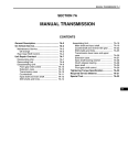
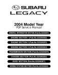
2004 LEGACY SERVICE MANUAL
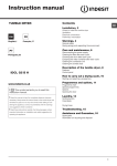
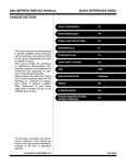
QUICK REFERENCE INDEX
ENGINE SECTION 2
This service manual has been prepared
to provide SUBARU service personnel
with the necessary information and data
for the correct maintenance and repair
of SUBARU vehicles.
This manual includes the procedures
for maintenance, disassembling, reassembling, inspection and adjustment of
components and diagnostics for guidance of experienced mechanics.
Please peruse and utilize this manual
fully to ensure complete repair work for
satisfying our customers by keeping
their vehicle in optimum condition.
When replacement of parts during
repair work is needed, be sure to use
SUBARU genuine parts.
FUEL INJECTION (FUEL SYSTEMS)
FU(H4DOTC)
EMISSION CONTROL
(AUX. EMISSION CONTROL DEVICES)
EC(H4DOTC)
INTAKE (INDUCTION)
IN(H4DOTC)
MECHANICAL
ME(H4DOTC)
EXHAUST
EX(H4DOTC)
COOLING
CO(H4DOTC)
LUBRICATION
LU(H4DOTC)
SPEED CONTROL SYSTEMS
SP(H4DOTC)
IGNITION
IG(H4DOTC)
STARTING/CHARGING SYSTEMS
SC(H4DOTC)
ENGINE (DIAGNOSTICS)
EN(H4DOTC)(diag)
All information, illustration and specifications contained in this manual are
based on the latest product information
available at the time of publication
approval.
FUJI HEAVY INDUSTRIES LTD.
G2320GE3
ENGINE (DIAGNOSTICS)
EN(H4DOTC)(diag)
1.
2.
3.
4.
5.
6.
7.
8.
9.
10.
11.
12.
13.
14.
15.
16.
17.
Page
Basic Diagnostic Procedure ........................................................................2
Check List for Interview...............................................................................3
General Description ....................................................................................5
Electrical Component Location ...................................................................8
Engine Control Module (ECM) I/O Signal .................................................15
Engine Condition Data ..............................................................................19
Data Link Connector .................................................................................20
Subaru Select Monitor...............................................................................21
Read Diagnostic Trouble Code (DTC) ......................................................27
Inspection Mode........................................................................................28
Clear Memory Mode..................................................................................30
Compulsory Valve Operation Check Mode ...............................................31
Malfunction Indicator Light ........................................................................33
Diagnostics for Engine Starting Failure.....................................................42
List of Diagnostic Trouble Code (DTC) .....................................................55
Diagnostic Procedure with Diagnostic Trouble Code (DTC) .....................60
General Diagnostic Table........................................................................202
Basic Diagnostic Procedure
ENGINE (DIAGNOSTICS)
1. Basic Diagnostic Procedure
A: PROCEDURE
1. ENGINE
1
Step
Check
CHECK ENGINE START FAILURE.
Does the engine start?
1) Ask the customer when and how the trouble occurred using the interview check list.
<Ref. to EN(H4DOTC)(diag)-3, CHECK, Check
List for Interview.>
2) Start the engine.
2
CHECK ILLUMINATION OF MALFUNCTION Does malfunction indicator
INDICATOR LIGHT.
light illuminate?
3
CHECK INDICATION OF DTC ON SCREEN. Is DTC displayed on the Sub1) Turn the ignition switch to OFF.
aru Select Monitor?
2) Connect the Subaru Select Monitor to data
link connector.
3) Turn the ignition switch to ON, and the Subaru Select Monitor switch to ON.
4) Read DTC on Subaru Select Monitor.
4
PERFORM THE DIAGNOSIS.
Is DTC displayed on the Sub1) Perform clear memory mode. <Ref. to
aru Select Monitor?
EN(H4DOTC)(diag)-30, Clear Memory Mode.>
2) Perform the inspection mode. <Ref. to
EN(H4DOTC)(diag)-28, Inspection Mode.>
EN(H4DOTC)(diag)-2
Yes
Go to step 2.
No
Inspection using
“Diagnostics for
Engine Starting
Failure”. <Ref. to
EN(H4DOTC)(diag
)-42, Diagnostics
for Engine Starting Failure.>
Go to step 3.
Inspection using
“General Diagnostic Table”. <Ref. to
EN(H4DOTC)(diag
)-202, General
Diagnostic Table.>
Record the DTC. Repair the related
Repair the trouble parts.
cause. <Ref. to
NOTE:
EN(H4DOTC)(diag If DTC is not
)-55, List of Diag- shown on display
nostic Trouble
although the malCode (DTC).> Go function indicator
to step 4.
light
illuminates,
perform the diagnostics for malfunction indicator
light circuit or combination
meter.
<Ref.
to
EN(H4DOTC)(diag)-33, Malfunction
Indicator
Light.>
Check on “DiagFinish the diagnonostic Chart with sis.
Diagnostic Trouble Code (DTC)”
<Ref. to
EN(H4DOTC)(diag
)-60, Diagnostic
Procedure with
Diagnostic Trouble Code (DTC).>
Check List for Interview
ENGINE (DIAGNOSTICS)
2. Check List for Interview
A: CHECK
1. CHECK LIST No. 1
Check the following items when problem has occurred.
NOTE:
Use copies of this page for interviewing customers.
Customer’s name
Date of sale
Date of repair
V.I.N.
Weather
Engine No.
Fuel brand
❏ Fine
❏ Cloudy
❏ Rainy
❏ Snowy
❏ Various/Others:
°C (°F)
Ambient air temperature
Place
Engine temperature
Engine speed
Vehicle speed
Driving conditions
Headlight
Blower
A/C compressor
Radiator fan
Front wiper
Rear wiper
km
miles
Odometer reading
❏ Hot
❏ Warm
❏ Cool
❏ Cold
❏ Highway
❏ Suburbs
❏ Inner city
❏ Uphill
❏ Downhill
❏ Rough road
❏ Others:
❏ Cold
❏ Warming-up
❏ After warming-up
❏ Any temperature
❏ Others:
rpm
km/h (MPH)
❏ Not affected
❏ At starting
❏ While idling
❏ At racing
❏ While accelerating
❏ While cruising
❏ While decelerating
❏ While turning (RH/LH)
❏ ON / ❏ OFF
❏ ON / ❏ OFF
❏ ON / ❏ OFF
❏ ON / ❏ OFF
❏ ON / ❏ OFF
❏ ON / ❏ OFF
Rear defogger
Audio
Car phone
EN(H4DOTC)(diag)-3
❏ ON / ❏ OFF
❏ ON / ❏ OFF
❏ ON / ❏ OFF
Check List for Interview
ENGINE (DIAGNOSTICS)
2. CHECK LIST No. 2
Check the following items about the vehicle’s state when malfunction indicator light turns on.
NOTE:
Use copies of this page for interviewing customers.
a) Other warning lights or indicators turn on. ❏ Yes / ❏ No
❏ Low fuel warning light
❏ Charge indicator light
❏ AT diagnostic indicator light
❏ ABS warning light
❏ Oil pressure indicator light
b) Fuel level
• Lack of gasoline: ❏ Yes / ❏ No
• Indicator position of fuel gauge:
• Experienced running out of fuel: ❏ Yes / ❏ No
c) Intentional connecting or disconnecting of harness connectors or spark plug cords: ❏ Yes / ❏ No
• What:
d) Intentional connecting or disconnecting of hoses: ❏ Yes / ❏ No
• What:
e) Installing of other parts except genuine parts: ❏ Yes / ❏ No
• What:
• Where:
f) Occurrence of noise: ❏ Yes / ❏ No
• From where:
• What kind:
g) Occurrence of smell: ❏ Yes / ❏ No
• From where:
• What kind:
h) Intrusion of water into engine compartment or passenger compartment: ❏ Yes / ❏ No
i) Troubles occurred
❏ Engine does not start.
❏ Engine stalls during idling.
❏ Engine stalls while driving.
❏ Engine speed decreases.
❏ Engine speed does not decrease.
❏ Rough idling
❏ Poor acceleration
❏ Back fire
❏ After fire
❏ Does not shift.
❏ Excessive shift shock
EN(H4DOTC)(diag)-4
General Description
ENGINE (DIAGNOSTICS)
3. General Description
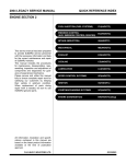
8) Use ECM mounting stud bolts as the grounding
point to the body when measuring voltage and resistance inside the passenger compartment.
A: CAUTION
1) Airbag system wiring harness is routed near the
ECM, main relay and fuel pump relay.
CAUTION:
• All airbag system wiring harnesses and connectors are colored yellow. Do not use the electrical test equipment on these circuits.
• Be careful not to damage the airbag system
wiring harness when servicing the ECM, TCM,
main relay and fuel pump relay.
2) Never connect the battery in reverse polarity.
The ECM will be destroyed instantly.
The fuel injector and other part will be damaged.
3) Do not disconnect the battery terminals while the
engine is running.
A large counter electromotive force will be generated in the generator, and this voltage may damage
electronic parts such as ECM, etc.
4) Before disconnecting the connectors of each
sensor and the ECM, be sure to turn the ignition
switch to OFF.
5) Poor contact has been identified as a primary
cause of this problem. Measure the voltage or resistance of individual sensor or all electrical control
modules using a tapered pin with a diameter of less
than 0.64 mm (0.025 in). Do not insert the pin more
than 5 mm (0.20 in) into the part.
6) Remove the ECM from the located position after
disconnecting two cables on battery.
Otherwise, the ECM may be damaged.
CAUTION:
When replacing the ECM, be careful not to use
the wrong spec. ECM to avoid any damage on
the fuel injection system.
NOTE:
Immobilizer system must be registered when installing the ECM of the model with immobilizer. For
doing so, all ignition keys and ID cards should be
prepared. Refer to “REGISTRATION MANUAL
FOR IMMOBILIZER”.
7) Connectors to each sensor in the engine compartment and the harness connectors on the engine side and body side are all designed to be
waterproof. However, it is still necessary to take
care not to allow water to get into the connectors
when washing the vehicle, or when servicing the
vehicle on a rainy day.
(A)
EN-00069
(A) Stud bolt
9) Use engine grounding terminal or engine proper
as the grounding point to the body when measuring
voltage and resistance in the engine compartment.
FU-01170
10) Every MFI-related part is a precision part. Do
not drop them.
11) Observe the following cautions when installing
a radio in MFI equipped models.
CAUTION:
• The antenna must be kept as far apart as possible from the control unit. (The ECM is located
under the steering column, inside of the instrument panel lower trim panel.)
• The antenna feeder must be placed as far
apart as possible from the ECM and MFI harness.
• Carefully adjust the antenna for correct
matching.
• When mounting a large power type radio, pay
special attention to the three items above mentioned.
• Incorrect installation of the radio may affect
the operation of the ECM.
12) Before disconnecting the fuel hose, disconnect
the fuel pump connector and crank the engine for
more than five seconds to release pressure in the
fuel system. If engine starts during this operation,
run it until it stops.
EN(H4DOTC)(diag)-5
General Description
ENGINE (DIAGNOSTICS)
13) Diagnostics should be conducted by rotating
with simple, easy operations and proceeding to
complicated, difficult operations. The most important thing in diagnostics is to understand the customer’s complaint, and distinguish between the
three causes.
14) On the model with ABS, when performing driving test in jacked-up or lifted-up position, sometimes the warning light may be lit, but this is not a
malfunction of the system. The reason for this is the
speed difference between the front and rear
wheels. After diagnosis of engine control system,
perform the ABS memory clearance procedure of
self-diagnosis function.
B: INSPECTION
Before performing diagnostics, check the following
items which might affect engine problems:
1. BATTERY
1) Measure battery voltage and specific gravity of
electrolyte.
Standard voltage: 12 V
Specific gravity: Above 1.260
2) Check the condition of the main and other fuses,
and harnesses and connectors. Also check for
proper grounding.
2. ENGINE GROUND
Make sure the engine grounding terminal is properly connected to the engine.
FU-01170
3. SELF-DIAGNOSIS FUNCTION
When detecting a malfunction by self-diagnosis
function on ECM, malfunction indicator light illuminates and malfunction occurrence is displayed.
Calling the self-diagnosis result is performed by
Subaru Select Monitor.
EN(H4DOTC)(diag)-6
General Description
ENGINE (DIAGNOSTICS)
C: PREPARATION TOOL
ILLUSTRATION
TOOL NUMBER
24082AA230
DESCRIPTION
CARTRIDGE
REMARKS
Troubleshooting for electrical system.
22771AA030
SUBARU SELECT
MONITOR KIT
Troubleshooting for electrical system.
• English: 22771AA030 (Without printer)
• German: 22771AA070 (Without printer)
• French: 22771AA080 (Without printer)
• Spanish: 22771AA090 (Without printer)
ST24082AA230
ST22771AA030
EN(H4DOTC)(diag)-7
Electrical Component Location
ENGINE (DIAGNOSTICS)
4. Electrical Component Location
A: LOCATION
1. ENGINE
• Control module
(4)
(2)
(3)
(1)
EN-02451
(1)
(2)
Engine control module (ECM)
Malfunction indicator light
(3)
Test mode connector
(4)
Data link connector
(1)
EN-01147
(2)
EN-01966
(4)
(3)
EN-02476
EN(H4DOTC)(diag)-8
EN-02477
Electrical Component Location
ENGINE (DIAGNOSTICS)
• Sensor
(5)
(8)
(1)
(7)
(6)
(5)
(3)
(2)
(4)
(6)
EN-01926
(1)
Manifold absolute pressure sensor
(2)
Engine coolant temperature sensor
(3)
(4)
(5)
(6)
Electronic throttle control
Knock sensor
Intake camshaft position sensor
Exhaust camshaft position sensor
EN(H4DOTC)(diag)-9
(7)
(8)
Crankshaft position sensor
Mass air flow and intake air temperature sensor
Electrical Component Location
ENGINE (DIAGNOSTICS)
(1)
(2)
EN-01927
EN-00295
(4)
(3)
EN-01928
EN-02169
(5)
(6)
EN-01798
EN-01929
(7)
(8)
EN-01930
EN(H4DOTC)(diag)-10
EN-02089
Electrical Component Location
ENGINE (DIAGNOSTICS)
(2)
(3)
(1)
(4)
EN-01931
(1)
(2)
Front oxygen (A/F) sensor
Front catalytic converter
(3)
Rear oxygen sensor
(4)
Rear catalytic converter
(3)
(1)
(2)
(4)
EN-01932
EN(H4DOTC)(diag)-11
EN-01933
Electrical Component Location
ENGINE (DIAGNOSTICS)
• Solenoid valve, actuator, emission control system parts and ignition system parts
(4)
(3)
(1)
(4)
(2)
(3)
(5)
(5)
EN-01934
(1)
(2)
(3)
Wastegate control solenoid valve
Purge control solenoid valve
Ignition coil
(4)
Intake oil flow control solenoid
valve
EN(H4DOTC)(diag)-12
(5)
Exhaust oil flow control solenoid
valve
Electrical Component Location
ENGINE (DIAGNOSTICS)
(3)
(2)
(1)
EN-01935
EN-01936
(5)
(4)
EN-01937
(1)
(8) (7) (6)
EN-01938
(2)
(9)
(5) (4)
(3)
EN-01898
(1)
(2)
(3)
Inhibitor switch
Fuel pump
Main relay
(4)
(5)
(6)
Fuel pump relay
Electronic throttle control relay
Radiator main fan relay 1
EN(H4DOTC)(diag)-13
(7)
(8)
(9)
Radiator sub fan relay
Radiator main fan relay 2
Starter
Electrical Component Location
ENGINE (DIAGNOSTICS)
(2)
EN-02093
EN-00178
(3)
(6)
(8)
(4)
(7)
(5)
EN-02094
(9)
EN-02096
EN(H4DOTC)(diag)-14
EN-02095
Engine Control Module (ECM) I/O Signal
ENGINE (DIAGNOSTICS)
5. Engine Control Module (ECM) I/O Signal
A: ELECTRICAL SPECIFICATION
To B135
To B134
7 6 5 4 3
17 16 15 14 13 12 11
27 26 25 24 23 22 21
34 33
32 31
2 1
10 9 8
20 19 18
30 29 28
To B136
7 6 5 4 3
2 1
19 18 17 16 15 14 13 12 11 10 9 8
27 26
25 24
23 22 21 20
35 34
33 32
31 30 29 28
6 5
4 3 2 1
16 15 14 13 12 11 10 9 8 7
27 26 25 24 23 22 21 20 19 18 17
30 29 28
35 34 33 32 31
To B137
7 6 5 4 3 2 1
17 16 15 14 13 12 11 10 9 8
25 24
23 22 21 20 19 18
31 30
29 28
27 26
EN-01812
Connector
No.
Terminal No.
Signal (+)
Crankshaft posi- Signal (−)
tion sensor Shield
Signal
Rear oxyShield
gen senGND
sor
(sensor)
Front oxy- Signal 1
gen (A/F)
sensor
Signal 2
heater
Rear oxygen sensor
heater signal
Engine
Signal
coolant
temperaGND
ture sen(sensor)
sor
Signal
Air flow
Shield
sensor
GND
Intake air temperature
sensor signal
Wastegate control solenoid valve
Starter switch
B135
B135
B135
B137
B137
Description
Signal (V)
Note
10
22
31
25
31
Ignition SW ON
(engine OFF)
0
0
0
0
0
Engine ON
(idling)
−7 — +7
0
0
0 — 0.9
0
Waveform
—
—
—
—
B136
35
0
0
—
B134
3
—
—
Waveform
B134
2
—
—
Waveform
B135
2
0 — 13
—
Waveform
B136
14
1.0 — 1.4
1.0 — 1.4
After engine is warmed-up.
B136
35
0
0
After engine is warmed-up.
B136
B136
B136
23
32
31
—
0
0
0.3 — 4.5
0
0
—
—
—
B136
13
0.3 — 4.6
0.3 — 4.6
—
B134
32
0 or 10 — 13
0 or 13 — 14
Waveform
B137
8
B137
17
Ignition switch
B137
14
Neutral position switch
B137
9
0
ON: 13 — 14
OFF: 0
13 — 14
ON: 0
OFF: 13 — 14
Cranking: 8 — 14
A/C switch
0
ON: 10 — 13
OFF: 0
10 — 13
ON: 0
OFF: 10 — 13
EN(H4DOTC)(diag)-15
—
—
—
Engine Control Module (ECM) I/O Signal
ENGINE (DIAGNOSTICS)
Connector
No.
Terminal No.
Sensor power supply
#1
#2
Ignition
control
#3
#4
#1
Fuel injec- #2
tor
#3
#4
Fuel pump Signal 1
control unit Signal 2
B137
B136
B136
B135
B135
B135
B136
B135
B135
B135
B135
B136
B136
B136
B136
B137
B135
15
25
33
19
5
6
16
18
17
16
16
6
5
4
3
28
27
A/C relay control
B135
33
B135
25
B135
24
B134
Description
Test mode connector
Signal
Knock
sensor
Shield
Back-up power supply
Control module power
supply
Radiator fan relay 1
control
Radiator fan relay 2
control
Malfunction indicator
light
Engine speed output
Purge control solenoid
valve
Signal
Manifold
Power
absolute
supply
pressure
GND
sensor
(sensor)
Blower fan switch
Power steering oil pressure switch
Front oxygen (A/F) sensor signal (+)
Front oxygen (A/F) sensor signal (−)
Front oxygen (A/F) sensor shield
SSM communication
line
GND (injector)
GND (sensor)
GND (ignition system)
GND (power supply)
GND (control system)
Signal (V)
Note
Ignition SW ON
(engine OFF)
10 — 13
2.8
0
10 — 13
10 — 13
10 — 13
5
0
0
0
0
10 — 13
10 — 13
10 — 13
10 — 13
10 — 13
0 or 5
ON: 0.5 or less
OFF: 10 — 13
ON: 0.5 or less
OFF: 10 — 13
ON: 0.5 or less
OFF: 10 — 13
Engine ON
(idling)
13 — 14
2.8
0
13 — 14
13 — 14
13 — 14
5
13 — 14
13 — 14
13 — 14
13 — 14
1 — 14
1 — 14
1 — 14
1 — 14
13 — 14
0 or 5
ON: 0.5 or less
OFF: 13 — 14
ON: 0.5 or less
OFF: 13 — 14
ON: 0.5 or less
OFF: 13 — 14
17
—
—
B134
23
B134
14
B136
22
—
ON: 1 or less
OFF: 10 — 13
1.7 — 2.4
0 — 13 or more
ON: 1 or less
OFF: 13 — 14
1.1 — 1.6
B136
16
5
5
B136
35
0
0
B137
13
ON: 0
OFF: 10 — 13
B137
10
10 — 13
ON: 0
OFF: 13 — 14
ON: 0
OFF: 13 — 14
B134
33
2.8 — 3.2
2.8 — 3.2
—
B134
26
2.4 — 2.7
2.4 — 2.7
—
B134
25
0
0
—
B137
20
B137
B136
B135
B135
B135
B137
B137
7
35
12
4
1
1
2
Less than 1←→ More
than 4
0
0
0
0
0
0
0
Less than 1←→ More
than 4
0
0
0
0
0
0
0
EN(H4DOTC)(diag)-16
When connected: 0
—
—
Ignition switch “OFF”: 10 — 13
—
—
—
Waveform
Waveform
Waveform
Waveform
Waveform
Waveform
Waveform
Waveform
—
Waveform
—
—
Model with A/C
Light “ON”: 1 or less
Light “OFF”: 10 — 14
Waveform
Waveform
—
With manual A/C model only
—
—
—
—
—
—
—
—
—
Engine Control Module (ECM) I/O Signal
ENGINE (DIAGNOSTICS)
Description
Terminal No.
B134
Signal (V)
Ignition SW ON
(engine OFF)
Engine ON
(idling)
Note
7
0
0
—
B134
6
0
0
—
B135
8
0 or 5
0 or 5
Waveform
B135
9
0 or 5
0 or 5
Waveform
Main
B136
18
0.64 — 0.72
Fully open: 3.96
Sub
B136
29
1.51 — 1.58
Fully open: 4.17
B136
16
5
5
—
B136
35
0
0
—
B137
5
Duty waveform
Duty waveform
Drive frequency: 500 Hz
B137
4
Duty waveform
Duty waveform
Drive frequency: 500 Hz
B137
6
10 — 13
13 — 14
—
B135
35
19
ON: 0
OFF: 13 — 14
ON: 13 — 14
OFF: 0
When ignition switch is turned
to ON: ON
B134
ON: 0
OFF: 10 — 13
ON: 10 — 13
OFF: 0
B134
29
0
0
—
B134
18
ON: 10 — 13
OFF: 0
ON: 13 — 14
OFF: 0
—
B134
28
0
0
—
B134
21
ON: 10 — 13
OFF: 0
ON: 13 — 14
OFF: 0
—
B134
31
0
0
—
B134
20
ON: 10 — 13
OFF: 0
ON: 13 — 14
OFF: 0
—
B134
30
0
0
—
B135
B135
20
28
0
0
−7 — +7
0
Waveform
—
B135
30
0
0
—
B135
B135
21
29
0
0
−7 — +7
0
Waveform
—
B135
30
0
0
—
GND (Front oxygen (A/
F) sensor heater 1)
GND (Front oxygen (A/
F) sensor heater 2)
Intake camshaft position sensor (LH)
Intake camshaft position sensor (RH)
Electronic
throttle
control
Connector
No.
Power
supply
GND
(sensor)
Electronic throttle control motor (+)
Electronic throttle control motor (−)
Electronic throttle control motor power supply
Electronic throttle control motor relay
Intake
Signal (+)
AVCS
solenoid
Signal (−)
(LH)
Intake
Signal (+)
AVCS
solenoid
Signal (−)
(RH)
Exhaust
Signal (+)
AVCS
solenoid
Signal (−)
(LH)
Exhaust
Signal (+)
AVCS
solenoid
Signal (−)
(RH)
Exhaust
Signal (+)
camshaft
Signal (−)
position
sensor
Shield
(LH)
Exhaust
Signal (+)
camshaft
Signal (−)
position
sensor
Shield
(RH)
0.64 — 0.72
(After engine is
warmed-up.)
1.51 — 1.58
(After engine is
warmed-up.)
EN(H4DOTC)(diag)-17
Fully closed: 0.6 Fully open:
3.96
Fully closed: 1.48 Fully open:
4.17
—
Engine Control Module (ECM) I/O Signal
ENGINE (DIAGNOSTICS)
Description
Connector
No.
Terminal No.
Main
B136
17
B136
Accelerator position
sensor
Signal (V)
Ignition SW ON
(engine OFF)
Fully closed: 1
Fully open: 3.3
Engine ON
(idling)
Fully closed: 1
Fully open: 3.3
Note
15
5
5
—
B136
34
0
0
—
Sub
B136
28
Shield
Power
supply
GND
(sensor)
B137
2
Fully closed: 1
Fully open: 3.3
0
Fully closed: 1
Fully open: 3.3
0
—
B136
16
5
5
—
B136
35
0
0
—
B135
32
ON: 0
OFF: 10 — 13
ON: 0
OFF: 10 — 13
5
When clutch pedal is
depressed: 0
When clutch pedal is
released: 10 — 13
When brake pedal is
depressed: 0
When brake pedal is
released: 10 — 13
When brake pedal is
depressed: 10 — 13
When brake pedal is
released: 0
When operating nothing: 3.5 — 4.5
When operating RES/
ACC: 2.5 — 3.5
When operating SET/
COAST: 0.5 — 1.5
When operating CANCEL: 0 — 0.5
ON: 0
OFF: 5
ON: 0
OFF: 13 — 14
ON: 0
OFF: 13 — 14
5
When clutch pedal is
depressed: 0
When clutch pedal is
released: 13 — 14
When brake pedal is
depressed: 0
When brake pedal is
released: 13 — 14
When brake pedal is
depressed: 13 — 14
When brake pedal is
released: 0
When operating nothing: 3.5 — 4.5
When operating RES/
ACC: 2.5 — 3.5
When operating SET/
COAST: 0.5 — 1.5
When operating CANCEL: 0 — 0.5
ON: 0
OFF: 5
Power
supply
GND
(sensor)
Starter relay
A/C middle pressure
switch
Clear memory switch
B136
30
B137
24
Clutch switch
B134
1
Brake switch 1
B136
9
Brake switch 2
B136
8
Cruise control command switch
B136
11
Cruise control main
switch
B136
7
EN(H4DOTC)(diag)-18
—
—
ON: Cranking
—
When connected: 0
—
—
—
—
—
Engine Condition Data
ENGINE (DIAGNOSTICS)
6. Engine Condition Data
A: ELECTRICAL SPECIFICATION
Remarks
Engine load
Specification
1.2 — 2.9 (%): Idling
4.7 — 12.8 (%): 2,500 rpm racing
Measuring condition:
• After engine is warmed-up.
• Gear position is in neutral.
• A/C is turned off.
• Turn all accessory switches to OFF.
EN(H4DOTC)(diag)-19
Data Link Connector
ENGINE (DIAGNOSTICS)
7. Data Link Connector
A: NOTE
This connector is used for Subaru Select Monitor.
CAUTION:
Do not connect any scan tools other than Subaru Select Monitor, because the circuit for the Subaru
Select Monitor may be damaged.
1
2
3
4
5
6
7
8
9 10 11 12 13 14 15 16
EN-00037
Terminal No.
1
2
3
4
5
6
7
8
Remarks
Power supply
Empty
Empty
Empty
Empty
Line end check signal 1
Empty
Empty
Terminal No.
9
10
11
12
13
14
15
16
Remarks
Empty
Subaru Select Monitor signal
Empty
Ground
Ground
Empty
Empty
Empty
EN(H4DOTC)(diag)-20
Subaru Select Monitor
ENGINE (DIAGNOSTICS)
8. Subaru Select Monitor
A: OPERATION
1. HOW TO USE SUBARU SELECT MONITOR
CAUTION:
Do not connect the scan tools except for Subaru Select Monitor.
5) Turn ignition switch to ON (engine OFF) and turn
Subaru Select Monitor switch to ON.
1) Prepare the Subaru Select Monitor kit. <Ref. to
EN(H4DOTC)(diag)-7, PREPARATION TOOL,
General Description.>
(A)
EN-00040
(A) Power switch
EN-00038
2) Connect the diagnosis cable to Subaru Select
Monitor.
3) Insert the cartridge to Subaru Select Monitor.
<Ref. to EN(H4DOTC)(diag)-7, PREPARATION
TOOL, General Description.>
6) Using the Subaru Select Monitor, call up DTC
and data, then record them.
2. READ DIAGNOSTIC TROUBLE CODE
(DTC) FOR ENGINE (NORMAL MODE)
Refer to “Read Diagnostic Trouble Code (DTC)” for
information about how to indicate DTC. <Ref. to
EN(H4DOTC)(diag)-27, Read Diagnostic Trouble
Code (DTC).>
3. READ DIAGNOSTIC TROUBLE CODE
(DTC) FOR ENGINE (OBD MODE)
Refer to “Read Diagnostic Trouble Code (DTC)” for
information about how to indicate DTC. <Ref. to
EN(H4DOTC)(diag)-27, Read Diagnostic Trouble
Code (DTC).>
EN-00039
4) Connect the Subaru Select Monitor to data link
connector.
(1) Data link connector is located in the lower
portion of the instrument panel (on the driver’s
side).
EN-02097
(2) Connect the diagnosis cable to data link
connector.
EN(H4DOTC)(diag)-21
Subaru Select Monitor
ENGINE (DIAGNOSTICS)
4. READ CURRENT DATA FOR ENGINE. (NORMAL MODE)
1) On the «Main Menu» display screen, select the {Each System Check} and press the [YES] key.
2) On the «System Selection Menu» display screen, select the {Engine} and press the [YES] key.
3) Press the [YES] key after the information of engine type was displayed.
4) On the «Engine Diagnosis» screen, select the {Current Data Display/Save}, and then press the [YES] key.
5) On the «Data Display Menu» screen, select the {Data Display} and press the [YES] key.
6) Using the scroll key, move the display screen up or down until the desired data is shown.
• A list of the support data is shown in the following table.
Remarks
Display
Unit
of measure
°C
%
%
mmHg
Note (at idling)
Engine coolant temperature signal
A/F correction 1
A/F learning 1
Intake manifold absolute pressure
Coolant Temp.
A/F Correction #1
A/F Learning #1
Mani. Absolute Pressure
Engine speed signal
Engine Speed
rpm
Vehicle speed signal
Ignition timing signal
Intake air temperature signal
Amount of intake air
Throttle opening angle signal
Rear oxygen sensor voltage
Battery voltage
Mass air flow voltage
Injection 1 pulse width
Knock sensor correction
Acceleration opening angle signal
Primary supercharged pressure control signal
Purge control solenoid duty ratio
Generator duty ratio
Fuel pump duty ratio
AVCS advance angle amount RH
AVCS advance angle amount LH
Oil flow control solenoid valve duty RH (AVCS)
Oil flow control solenoid valve duty LH (AVCS)
Oil flow control solenoid valve current RH
Oil flow control solenoid valve current LH
A/F sensor current value 1
km/h
deg
°C
g/s
%
V
V
V
ms
deg
%
%
%
%
%
deg
deg
%
%
mA
mA
mA
ohm
27 — 35 mA
A/F sensor output lambda 1
A/F correction 3
Throttle motor duty
Throttle power supply voltage
Sub throttle sensor voltage
Main throttle sensor voltage
Sub accelerator sensor voltage
Main accelerator sensor voltage
Atmospheric pressure signal
Vehicle Speed
Ignition Timing
Intake Air Temp.
Mass Air Flow
Throttle Opening Angle
Rear O2 Sensor
Battery Voltage
Air Flow Sensor Voltage
Fuel Injection #1 Pulse
Knock Correction
Accel. Opening Angle
Primary Control
CPC Valve Duty Ratio
ALT Duty
Fuel Pump Duty
VVT Adv. Ang. Amount R
VVT Adv. Ang. Amount L
OCV Duty R
OCV Duty L
OCV Current R
OCV Current L
A/F Sensor #1 Current
A/F Sensor #1 Resistance
A/F Sensor #1
A/F Correction #3
Throttle Motor Duty
Throttle Motor Voltage
Sub-throttle Sensor
Main-throttle Sensor
Sub-accelerator Sensor
Main-accelerator Sensor
Atmospheric Pressure
80 — 100°C
−10 — +10%
−15 — +15%
220 — 275 mmHg
630 — 770 rpm (Agree
with the tachometer indication)
0 km/h (at parking)
10 — 15 deg
20 — 50°C
2.1 — 3.1 g/s
2.0 — 2.4%
0 — 1.0 V
12 — 15 V
1.0 — 1.7 V
1.2 — 2.2 ms
0.0 deg
0.0%
0.0%
0 — 25%
0 — 100%
30 — 40%
±5 deg
±5 deg
0 — 20%
0 — 20%
40 — 100 mA
40 — 100 mA
−20 — 20 mA
—
%
%
V
V
V
V
V
mmHg
Intake manifold relative pressure
Mani. Relative Pressure
mmHg
1.0
0.00%
−5%
12 — 15 V
1.5 V
0.6 V
1.1 V
1.0 V
—
Intake manifold absolute
pressure − Atmospheric
pressure
A/F sensor resistance value 1
EN(H4DOTC)(diag)-22
Subaru Select Monitor
ENGINE (DIAGNOSTICS)
Remarks
Display
Memory vehicle speed
Estimated cumulative driving distance
Exhaust AVCS retard angle amount RH
Exhaust AVCS retard angle amount LH
Exhaust oil flow control solenoid valve duty ratio RH
Exhaust oil flow control solenoid valve duty ratio LH
Exhaust oil flow control solenoid valve current value RH
Exhaust oil flow control solenoid valve current value LH
Memorized Cruise
Speed
Estimated Cumulative
Driving Distance
Exh. VVT Retard Ang. R
Exh. VVT Retard Ang. L
Exh. OCV Duty R
Exh. OCV Duty L
Exh. OCV Current R
Exh. OCV Current L
Unit
of measure
Note (at idling)
km/h
—
km
—
deg
deg
%
%
mA
mA
±5 deg
±5 deg
0 — 20%
0 — 20%
40 — 100 mA
40 — 100 mA
NOTE:
For detailed operation procedure, refer to the “SUBARU SELECT MONITOR OPERATION MANUAL”.
EN(H4DOTC)(diag)-23
Subaru Select Monitor
ENGINE (DIAGNOSTICS)
5. READ CURRENT DATA FOR ENGINE (OBD MODE)
1) On the «Main Menu» display screen, select the {Each System Check} and press the [YES] key.
2) On the «System Selection Menu» display screen, select the {Engine} and press the [YES] key.
3) Press the [YES] key after the information of engine type was displayed.
4) On the «Engine Diagnosis» display screen, select the {OBD System} and press the [YES] key.
5) On the «OBD Menu» screen, select the {Current Data Display/Save}, and then press the [YES] key.
6) On the «Data Display Menu» screen, select the {Data Display} and press the [YES] key.
7) Using the scroll key, move the display screen up or down until the desired data is shown.
• A list of the support data is shown in the following table.
Description
Number of diagnosis code
Condition of malfunction indicator light
Monitoring test of misfire
Monitoring test of fuel system
Monitoring test of comprehensive component
Test of catalyst
Test of heating-type catalyst
Test of evaporative emission purge control system
Test of secondary air system
Test of air conditioning system refrigerant
Test of oxygen sensor
Test of oxygen sensor heater
Test of EGR system
Display
Number of Diag. Code:
MI (MIL)
Misfire monitoring
Fuel system monitoring
Component monitoring
Catalyst Diagnosis
Heated catalyst
Evaporative purge system
Secondary air system
A/C system refrigerant
Oxygen sensor
O2 Heater Diagnosis
EGR system
Unit of measure
—
ON or OFF
no support
complete or incomplete
complete or incomplete
no support
no support
no support
no support
no support
complete or incomplete
complete or incomplete
no support
NOTE:
For detailed operation procedure, refer to the “SUBARU SELECT MONITOR OPERATION MANUAL”.
EN(H4DOTC)(diag)-24
Subaru Select Monitor
ENGINE (DIAGNOSTICS)
6. LED OPERATION MODE FOR ENGINE
1) On the «Main Menu» display screen, select the {Each System Check} and press the [YES] key.
2) On the «System Selection Menu» display screen, select the {Engine} and press the [YES] key.
3) Press the [YES] key after the information of engine type was displayed.
4) On the «Engine Diagnosis» screen, select the {Current Data Display/Save}, and then press the [YES] key.
5) On the «Data Display» screen, select the {Data & LED Display} and press the [YES] key.
6) Using the scroll key, move the display screen up or down until the desired data is shown.
• A list of the support data is shown in the following table.
Remarks
AT/MT identification signal
Display
AT Vehicle ID Signal
Message
ON or OFF
Test mode signal
Test Mode Signal
ON or OFF
Clear memory signal
Clear Memory Terminal
ON or OFF
Neutral position switch signal
Neutral Position Switch
ON or OFF
Idle switch signal
Idle Switch Signal
ON or OFF
Ignition switch signal
Ignition Switch
ON or OFF
Power steering switch signal
P/S Switch
ON or OFF
Handle switch signal
Handle SW
LHD or RHD
Starter switch signal
Starter Switch
ON or OFF
Air conditioning switch signal
A/C Switch
ON or OFF
Rear O2 Rich Signal
ON or OFF
Knocking Signal
ON or OFF
Crankshaft Position Signal
ON or OFF
Camshaft Position Signal
ON or OFF
Rear defogger switch signal
Rear Defogger Switch
ON or OFF
Blower fan switch signal
Blower Fan Switch
ON or OFF
Small light switch signal
Light Switch
ON or OFF
Rear oxygen sensor rich signal
Knocking signal
Crankshaft position sensor
signal
Camshaft position sensor signal
Windshield wiper switch signal Wiper SW
ON or OFF
A/C middle pressure switch
signal
A/C Mid Pressure Switch
ON or OFF
Air conditioning relay signal
A/C Compressor Signal
ON or OFF
Radiator fan relay 1 signal
Radiator Fan Relay #1
ON or OFF
Radiator fan relay 2 signal
Radiator Fan Relay #2
ON or OFF
AT retard angle demand signal Retard Signal
ON or OFF
AT fuel cut signal
ON or OFF
Fuel Cut
EN(H4DOTC)(diag)-25
LED “ON” requirements
Illuminate (AT model)
When test mode connector is
connected.
When clear memory connector is connected.
When neutral position signal is
entered.
When idle switch signal is
entered.
When ignition switch is turned
to ON.
When power steering switch is
entered.
When handle switch signal is
input.
When starter switch is input.
When air conditioning switch is
input.
When rear oxygen sensor mixture ratio is rich.
When knocking signal is input.
When crankshaft position sensor signal is input.
When camshaft position sensor signal is input.
When rear defogger switch is
turned to ON.
When blower fan switch is
turned to ON.
When small light switch is
turned to ON.
When windshield wiper switch
is turned to ON.
When A/C middle pressure
switch is turned to ON.
When air conditioning relay is
in function.
When radiator fan relay 1 is in
function.
When radiator fan relay 2 is in
function.
When AT retard angle demand
signal is input.
When AT fuel cut signal is
input.
Subaru Select Monitor
ENGINE (DIAGNOSTICS)
Remarks
Display
Message
Torque down output signal
Torque Down Output
ON or OFF
Torque down demand signal
Request Torque Down
ON or OFF
Torque Control Permission
ON or OFF
ETC Motor Relay
ON or OFF
Clutch switch signal
Clutch Switch
ON or OFF
Stop light switch signal
Stop Light Switch
ON or OFF
SET/COAST switch signal
SET/COAST Switch
ON or OFF
RES/ACC switch signal
RESUME/ACCEL Switch
ON or OFF
Brake switch signal
Brake Switch
ON or OFF
Main switch signal
Main Switch
ON or OFF
Cancel switch signal
Cancel Switch
ON or OFF
Data reception signal
Body Int. Unit Data
ON or OFF
Counter update signal
Body Int. Unit Count
ON or OFF
AT coordinate permission signal
Electronic throttle control
motor relay signal
LED “ON” requirements
When torque down output signal is input.
When torque down demand
signal is input.
When AT coordinate permission signal is input.
When electronic throttle control motor relay is in function.
When clutch switch is turned
to ON.
When stop switch is turned to
ON.
When SET/COAST switch is
turned to ON.
When RES/ACC switch is
turned to ON.
When brake switch is turned to
ON.
When main switch is turned to
ON.
When cancel switch is turned
to ON.
When data reception signal is
entered.
When counter update signal is
entered.
NOTE:
For detailed operation procedure, refer to the “SUBARU SELECT MONITOR OPERATION MANUAL”.
EN(H4DOTC)(diag)-26
Read Diagnostic Trouble Code (DTC)
ENGINE (DIAGNOSTICS)
9. Read Diagnostic Trouble
Code (DTC)
A: OPERATION
1. SUBARU SELECT MONITOR (NORMAL
MODE)
1) On the «Main Menu» display screen, select the
{Each System Check} and press the [YES] key.
2) On the «System Selection Menu» display
screen, select the {Engine} and press the [YES]
key.
3) Press the [YES] key after the information of engine type was displayed.
4) On the «Engine Diagnosis» screen, select the
{DTC Display}, and then press the [YES] key.
5) On the «Diagnostic Code(s) Display» screen,
select the {Current Diagnostic Code(s)} or {History
Diagnostic Code(s)}, and then press the [YES] key.
NOTE:
• For detailed operation procedure, refer to the
“SUBARU SELECT MONITOR OPERATION
MANUAL”.
• For details concerning DTCs, refer to the List of
Diagnostic Trouble Code (DTC). <Ref. to
EN(H4DOTC)(diag)-55, List of Diagnostic Trouble
Code (DTC).>
2. SUBARU SELECT MONITOR (OBD
MODE)
1) On the «Main Menu» display screen, select the
{Each System Check} and press the [YES] key.
2) On the «System Selection Menu» display
screen, select the {Engine} and press the [YES]
key.
3) Press the [YES] key after the information of engine type was displayed.
4) On the «Engine Diagnosis» display screen, select the {OBD System} and press the [YES] key.
5) On the «OBD Menu» display screen, select the
{DTC Display} and press the [YES] key.
6) Make sure DTC is shown on the screen.
NOTE:
• For detailed operation procedure, refer to the
“SUBARU SELECT MONITOR OPERATION
MANUAL”.
• For details concerning DTCs, refer to the List of
Diagnostic Trouble Code (DTC). <Ref. to
EN(H4DOTC)(diag)-55, List of Diagnostic Trouble
Code (DTC).>
EN(H4DOTC)(diag)-27
Inspection Mode
ENGINE (DIAGNOSTICS)
10.Inspection Mode
2. SUBARU SELECT MONITOR
A: PROCEDURE
1) After clearing the memory, check for any remaining
unresolved
trouble
data.
<Ref.
to
EN(H4DOTC)(diag)-30, Clear Memory Mode.>
2) Idle the engine.
3) Prepare the Subaru Select Monitor kit. <Ref. to
EN(H4DOTC)(diag)-7, PREPARATION TOOL,
General Description.>
1. PREPARATION FOR THE INSPECTION
MODE
1) Check battery voltage is more than 12 V and fuel
remains half [20 to 40 2 (5.3 to 10.6 US gal, 4.4 to
8.8 Imp gal)].
2) Lift-up the vehicle using a garage jack and place
it on rigid racks, or drive the vehicle onto free rollers.
WARNING:
• Before lifting-up the vehicle, ensure parking
brakes are applied.
• Do not use a pantograph jack in place of a rigid rack.
• Secure a rope or wire to the front or rear towing hooks to prevent the lateral runout of front
wheels.
• Do not abruptly depress/release clutch pedal
or accelerator pedal during works even when
the engine is operating at low speeds since this
may cause vehicle to jump off free rollers.
• In order to prevent the vehicle from slipping
due to vibration, do not place any wooden
blocks or similar items between the rigid racks
and the vehicle.
• Since the rear wheels will also rotate, do not
place anything near them. Also, make sure that
nobody goes in front of the vehicle.
EN-00038
4) Connect the diagnosis cable to Subaru Select
Monitor.
5) Insert the cartridge to Subaru Select Monitor.
<Ref. to EN(H4DOTC)(diag)-7, PREPARATION
TOOL, General Description.>
EN-00039
6) Connect the test mode connector (A) located at
the lower portion of glove box.
(A)
(A)
EN-01983
(B)
EN-00041
(A) Rigid rack
(B) Free rollers
EN(H4DOTC)(diag)-28
Inspection Mode
ENGINE (DIAGNOSTICS)
7) Connect the Subaru Select Monitor to data link
connector located in the lower portion of the instrument panel (on the driver’s side).
• Release the parking brake.
• The speed difference between front and rear
wheels may light either the ABS warning light, but
this indicates no malfunctions. When engine control diagnosis is finished, perform the ABS memory
clearance procedure of self-diagnosis function.
EN-02097
CAUTION:
Do not connect the scan tools except for Subaru Select Monitor.
8) Turn the ignition switch to ON (engine OFF) and
Subaru Select Monitor switch to ON.
(A)
EN-00040
(A) Power switch
9) On the «Main Menu» display screen, select the
{Each System Check} and press the [YES] key.
10) On the «System Selection Menu» display
screen, select the {Engine} and press the [YES]
key.
11) Press the [YES] key after the information of engine type was displayed.
12) On the «Engine Diagnosis» screen, select the
{D Check} and press the [YES] key.
13) When the “Perform D Check?” is shown on the
screen, press the [YES] key.
14) Perform subsequent procedures as instructed
on the display screen.
• If trouble still remains in the memory, the corresponding DTC appears on the display screen.
NOTE:
• For detailed operation procedure, refer to the
“SUBARU SELECT MONITOR OPERATION
MANUAL”.
• For details concerning DTCs, refer to the List of
Diagnostic Trouble Code (DTC).
<Ref. to EN(H4DOTC)(diag)-55, List of Diagnostic
Trouble Code (DTC).>
EN(H4DOTC)(diag)-29
Clear Memory Mode
ENGINE (DIAGNOSTICS)
11.Clear Memory Mode
A: OPERATION
1. SUBARU SELECT MONITOR (NORMAL
MODE)
1) On the «Main Menu» display screen, select the
{Each System Check} and press the [YES] key.
2) On the «System Selection Menu» display
screen, select the {Engine} and press the [YES]
key.
3) Press the [YES] key after the information of engine type was displayed.
4) On the «Engine Diagnosis» display screen, select the {Memory Clear} and press the [YES] key.
5) When the “Done” and “Turn Ignition Switch OFF”
are shown on the display screen, turn the ignition
switch to OFF and then Subaru Select Monitor to
OFF.
NOTE:
For detailed operation procedure, refer to the
“SUBARU SELECT MONITOR OPERATION
MANUAL”.
2. SUBARU SELECT MONITOR (OBD
MODE)
1) On the «Main Menu» display screen, select the
{Each System Check} and press the [YES] key.
2) On the «System Selection Menu» display
screen, select the {Engine} and press the [YES]
key.
3) Press the [YES] key after the information of engine type was displayed.
4) On the «Engine Diagnosis» display screen, select the {OBD System} and press the [YES] key.
5) On the «OBD Menu» display screen, select the
{DTC Clear} and press the [YES] key.
6) When the “Perform Diagnostic Code(s) Clear?”
is shown on the screen, press the [YES] key.
7) Turn the ignition switch to OFF and then turn the
Subaru Select Monitor switch to OFF.
NOTE:
For detailed operation procedure, refer to the
“SUBARU SELECT MONITOR OPERATION
MANUAL”.
EN(H4DOTC)(diag)-30
Compulsory Valve Operation Check Mode
ENGINE (DIAGNOSTICS)
12.Compulsory Valve Operation
Check Mode
5) Connect the Subaru Select Monitor to data link
connector located in the lower portion of the instrument panel (on the driver’s side).
A: OPERATION
1) Prepare the Subaru Select Monitor kit. <Ref. to
EN(H4DOTC)(diag)-7, PREPARATION TOOL,
General Description.>
EN-02097
EN-00038
2) Connect the diagnosis cable to Subaru Select
Monitor.
3) Insert the cartridge to Subaru Select Monitor.
<Ref. to EN(H4DOTC)(diag)-7, PREPARATION
TOOL, General Description.>
CAUTION:
Do not connect the scan tools except for Subaru Select Monitor.
6) Turn ignition switch to ON (engine OFF) and turn
Subaru Select Monitor switch to ON.
(A)
EN-00040
(A) Power switch
EN-00039
4) Connect the test mode connector (A) located at
the lower portion of glove box.
(A)
EN-01983
7) On the «Main Menu» display screen, select the
{Each System Check} and press the [YES] key.
8) On the «System Selection Menu» display
screen, select the {Engine} and press the [YES]
key.
9) Press the [YES] key after the information of engine type was displayed.
10) On the «Engine Diagnosis» display screen, select the {System Operation Check Mode} and press
the [YES] key.
11) On the «System Operation Check Mode»
screen, select the {Actuator ON/OFF Operation}
and press the [YES] key.
12) On the «Actuator ON/OFF Operation» screen,
select the desired compulsory actuator and press
the [YES] key.
13) Pressing the [NO] key completes the compulsory valve operation check mode. The display will
then return to the «Actuator ON/OFF Operation»
screen.
EN(H4DOTC)(diag)-31
Compulsory Valve Operation Check Mode
ENGINE (DIAGNOSTICS)
• A list of the support data is shown in the following
table.
Description
Compulsory fuel pump relay operation
check
Compulsory radiator fan relay operation
check
Compulsory air conditioning relay operation check
Compulsory purge control solenoid
valve operation check
Compulsory wastegate control solenoid valve operation check
Display
Fuel Pump
Radiator Fan
Relay
A/C Compressor
Relay
CPC Solenoid
Wastegate control solenoid
NOTE:
• The following parts will be displayed but not functional.
Display
EGR Solenoid
ASV Solenoid
FICD Solenoid
Pressure Switching Solenoid
PCV Solenoid
AAI Solenoid
Vcut Solenoid
Fuel Tank Sensor Control Valve
• For detailed operation procedure, refer to the
“SUBARU SELECT MONITOR OPERATION
MANUAL”.
EN(H4DOTC)(diag)-32
Malfunction Indicator Light
ENGINE (DIAGNOSTICS)
13.Malfunction Indicator Light
A: PROCEDURE
1. Activation of malfunction indicator light. <Ref. to EN(H4DOTC)(diag)-34, ACTIVATION OF MALFUNCTION INDICATOR
LIGHT, Malfunction Indicator Light.>
↓
2. Check that the malfunction indicator light does not come on. <Ref. to EN(H4DOTC)(diag)-35, MALFUNCTION INDICATOR
LIGHT DOES NOT COME ON, Malfunction Indicator Light.>
↓
3. Check that the malfunction indicator light does not go off. <Ref. to EN(H4DOTC)(diag)-37, MALFUNCTION INDICATOR LIGHT
DOES NOT GO OFF., Malfunction Indicator Light.>
↓
4. Check that the malfunction indicator light does not blink. <Ref. to EN(H4DOTC)(diag)-38, MALFUNCTION INDICATOR LIGHT
DOES NOT BLINK., Malfunction Indicator Light.>
↓
5. Check that the malfunction indicator light remains blinking. <Ref. to EN(H4DOTC)(diag)-40, MALFUNCTION INDICATOR
LIGHT REMAINS BLINKING., Malfunction Indicator Light.>
EN(H4DOTC)(diag)-33
Malfunction Indicator Light
ENGINE (DIAGNOSTICS)
B: ACTIVATION OF MALFUNCTION
INDICATOR LIGHT
1) When the ignition switch is turned to ON (engine
OFF), the malfunction indicator light (A) in the combination meter illuminates.
(3) Malfunction indicator light blinks at a cycle of
3 Hz after diagnosis if there is no trouble. Malfunction indicator light illuminates if faulty.
(1)
NOTE:
If the malfunction indicator light does not illuminate,
perform the diagnosis of malfunction indicator light
circuit or the combination meter circuit. <Ref. to
EN(H4DOTC)(diag)-35, MALFUNCTION INDICATOR LIGHT DOES NOT COME ON, Malfunction
Indicator Light.>
(2)
(4)
(3)
EN-01681
(1)
(2)
(3)
(4)
(A)
ON
OFF
Ignition switch ON
1 second
EN-01984
2) After starting the engine, the malfunction indicator light goes out. If it does not, either the engine or
the emission control system is malfunctioning.
(1)
(3)
(4)
(2)
(3)
(4)
(5)
(6)
EN-01679
(1)
(2)
(3)
(4)
(5)
(6)
No trouble
Trouble occurs
ON
OFF
Ignition switch ON
Engine start
3) Turn the ignition switch to OFF and connect the
test mode connector.
(1) When the ignition switch is turned to ON
(engine OFF), the malfunction indicator light illuminates.
(2) Malfunction indicator light blinks at a cycle of
0.5 Hz after starting the engine. (During diagnosis)
EN(H4DOTC)(diag)-34
Malfunction Indicator Light
ENGINE (DIAGNOSTICS)
C: MALFUNCTION INDICATOR LIGHT DOES NOT COME ON
DIAGNOSIS:
The malfunction indicator light circuit is open or shorted.
TROUBLE SYMPTOM:
When the ignition switch is turned to ON (engine OFF), malfunction indicator light does not come on.
WIRING DIAGRAM:
B72
IGNITION
SWITCH
BATTERY
SBF-7
No.5
6
SBF-1
3
3
4
16
COMBINATION
METER
8
i3
i10
17
B38
ECM
E
B134
i10
B72
B38
6 7 8 9 10
1 2 3 4 5
11 12 13 14 15 16 17 18 19 20 21 22
1 2 3
4 5 6
1 2 3 4
5 6 7 8 9
10 11 12 13 14 15 16 17 18 19 20
B134
1
8 9
18 19
28 29
2
10
20
30
3 4 5 6 7
11 12 13 14 15 16 17
21 22 23 24 25 26 27
33 34
31 32
EN-01939
EN(H4DOTC)(diag)-35
Malfunction Indicator Light
ENGINE (DIAGNOSTICS)
1
2
3
4
5
6
Step
CHECK OUTPUT SIGNAL FROM ECM.
1) Turn the ignition switch to ON.
2) Measure the voltage between ECM connector and chassis ground.
Connector & terminal
(B134) No. 17 (+) — Chassis ground (−):
CHECK POOR CONTACT.
Check for poor connection when shaking or
pulling ECM connector and harness.
CHECK ECM CONNECTOR.
Check the connection of ECM connector.
CHECK HARNESS BETWEEN COMBINATION METER AND ECM CONNECTOR.
1) Turn the ignition switch to OFF.
2) Remove the combination meter. <Ref. to
IDI-16, Combination Meter Assembly.>
3) Disconnect the connector from ECM and
combination meter.
4) Measure the resistance of harness
between ECM and combination meter connector.
Connector & terminal
(B134) No. 17 — (i10) No. 16:
Check
Is the voltage less than 1 V?
Yes
Go to step 4.
Does malfunction indicator
light illuminate?
Repair the poor
contact in ECM
connector.
Is the ECM connector correctly Replace the ECM.
connected?
<Ref. to
FU(H4DOTC)-35,
Engine Control
Module (ECM).>
Is the resistance less than 1
Go to step 5.
Ω?
CHECK POOR CONTACT.
Is there poor contact in combi- Repair the poor
Check poor contact in combination meter con- nation meter connector?
contact in combinector.
nation meter connector.
Is the voltage more than 10 V? Replace the board
CHECK HARNESS BETWEEN COMBINAof combination
TION METER AND IGNITION SWITCH CONmeter. <Ref. to IDINECTOR.
16, Combination
1) Turn the ignition switch to ON.
Meter Assembly.>
2) Measure the voltage between combination
meter connector and chassis ground.
Connector & terminal
(i10) No. 3 (+) — Chassis ground (−):
(i10) No. 4 (+) — Chassis ground (−):
EN(H4DOTC)(diag)-36
No
Go to step 2.
Go to step 3.
Repair the connection of ECM
connector.
Repair the harness and connector.
NOTE:
In this case, repair
the following:
• Open circuit in
harness between
ECM and combination meter connector
• Poor contact in
coupling connector
Go to step 6.
Check the following and repair if
necessary.
NOTE:
• Blown out fuse
• Open or short
circuit in harness
between fuse and
battery terminal
• Poor contact in
ignition switch connector
Malfunction Indicator Light
ENGINE (DIAGNOSTICS)
D: MALFUNCTION INDICATOR LIGHT DOES NOT GO OFF.
DIAGNOSIS:
The malfunction indicator light circuit is shorted.
TROUBLE SYMPTOM:
Although malfunction indicator light comes on when the engine runs, DTC is not shown on the Subaru Select
Monitor display.
WIRING DIAGRAM:
B72
IGNITION
SWITCH
BATTERY
SBF-7
No.5
6
SBF-1
3
3
4
16
COMBINATION
METER
8
i3
i10
17
B38
ECM
E
B134
i10
B72
B38
6 7 8 9 10
1 2 3 4 5
11 12 13 14 15 16 17 18 19 20 21 22
1 2 3
4 5 6
1 2 3 4
5 6 7 8 9
10 11 12 13 14 15 16 17 18 19 20
B134
1
8 9
18 19
28 29
2
10
20
30
3 4 5 6 7
11 12 13 14 15 16 17
21 22 23 24 25 26 27
33 34
31 32
EN-01939
1
Step
CHECK HARNESS BETWEEN COMBINATION METER AND ECM CONNECTOR.
1) Turn the ignition switch to OFF.
2) Disconnect the connector from ECM.
3) Turn the ignition switch to ON.
Check
Does malfunction indicator
light illuminate?
EN(H4DOTC)(diag)-37
Yes
Repair the short
circuit in harness
between combination meter and
ECM connector.
No
Replace the ECM.
<Ref. to
FU(H4DOTC)-35,
Engine Control
Module (ECM).>
Malfunction Indicator Light
ENGINE (DIAGNOSTICS)
E: MALFUNCTION INDICATOR LIGHT DOES NOT BLINK.
DIAGNOSIS:
• The malfunction indicator light circuit is open or shorted.
• Test mode connector circuit is in open.
TROUBLE SYMPTOM:
Malfunction indicator light does not blink during inspection mode.
WIRING DIAGRAM:
IGNITION
SWITCH
B72
BATTERY
SBF-7
No.5
6
SBF-1
3
3
4
16
COMBINATION
METER
1
1
B75
B76
i3
8
B38
*
*
A17
D15
B138
A: B134
B75
B76
B72
1
2
1
2
1 2 3
4 5 6
C19
i10
C: B136
D: B137
2
10
20
30
: TERMINAL NO. RANDOM ARRANGEMENT
ECM
A: B134
1
8 9
18 19
28 29
*
3 4 5 6 7
11 12 13 14 15 16 17
21 22 23 24 25 26 27
33 34
31 32
E
C:
B136
1 2 3 4
7 8 9 10 11 12 13
17 18 19 20 21 22 23 24
28 29 30
31 32
i10
B38
B138
6 7 8 9 10
1 2 3 4 5
11 12 13 14 15 16 17 18 19 20 21 22
1 2 3 4
5 6 7 8 9
10 11 12 13 14 15 16 17 18 19 20
1 2 3 4
5 6 7 8
D: B137
5 6
14 15 16
25 26 27
33 34 35
1 2 3 4 5 6 7
8 9 10 11 12 13 14 15 16 17
18 19 20 21 22 23
24 25
28 29
30 31
26 27
EN-02401
EN(H4DOTC)(diag)-38
Malfunction Indicator Light
ENGINE (DIAGNOSTICS)
Step
CHECK STATUS OF MALFUNCTION INDICATOR LIGHT.
1) Turn the ignition switch to OFF.
2) Disconnect the test mode connectors.
3) Turn the ignition switch to ON. (engine
OFF)
Check
Does malfunction indicator
light illuminate?
2
CHECK HARNESS BETWEEN COMBINATION METER AND ECM CONNECTOR.
1) Turn the ignition switch to OFF.
2) Disconnect the connector from ECM.
3) Turn the ignition switch to ON.
Does malfunction indicator
light illuminate?
3
CHECK HARNESS BETWEEN TEST MODE Is the resistance less than 1
CONNECTOR AND ECU.
Ω?
1) Turn the ignition switch to OFF.
2) Disconnect the connector from ECM.
3) Measure the resistance of harness
between test mode connector and ECM.
Connector & terminal
(B76) No. 1 — (B136) No. 19:
1
4
CHECK POOR CONTACT.
Check poor contact in ECM connector.
Is the poor contact in ECM
connector?
5
CHECK HARNESS BETWEEN ECM AND
TEST MODE CONNECTOR.
Measure the resistance of harness between
ECM and test mode connector.
Connector & terminal
(B137) No. 15 — (B75) No. 1:
CHECK POOR CONTACT.
Check poor contact in ECM connector.
Is the resistance less than 1
Ω?
6
Is the poor contact in ECM
connector?
EN(H4DOTC)(diag)-39
Yes
Go to step 2.
No
Repair the malfunction indictor
light circuit.
<Ref. to
EN(H4DOTC)(diag
)-35, MALFUNCTION INDICATOR LIGHT
DOES NOT
COME ON, Malfunction Indicator
Light.>
Repair the ground Go to step 3.
short circuit in harness between
combination meter
and ECM connector.
Go to step 4.
Repair the harness and connector.
Repair the poor
contact in ECM
connector.
Go to step 6.
Repair the poor
contact in ECM
connector.
NOTE:
In this case, repair
the following:
• Open circuit in
harness between
test mode connector and ECM
• Poor contact in
joint connector
Go to step 5.
Repair the open
circuit in harness
between ECM and
test mode connector.
Replace the ECM.
<Ref. to
FU(H4DOTC)-35,
Engine Control
Module (ECM).>
Malfunction Indicator Light
ENGINE (DIAGNOSTICS)
F: MALFUNCTION INDICATOR LIGHT REMAINS BLINKING.
DIAGNOSIS:
Test mode connector circuit is shorted.
TROUBLE SYMPTOM:
Malfunction indicator light blinks when test mode connector is not connected.
WIRING DIAGRAM:
IGNITION
SWITCH
B72
BATTERY
SBF-7
No.5
6
SBF-1
3
3
4
16
COMBINATION
METER
8
B38
B75
B76
*
*
B138
D15
A17
A: B134
1
2
1
B76
B72
1
2
1 2 3
4 5 6
C19
i10
B75
1
i3
C: B136
D: B137
2
10
20
30
: TERMINAL NO. RANDOM ARRANGEMENT
ECM
A: B134
1
8 9
18 19
28 29
*
3 4 5 6 7
11 12 13 14 15 16 17
21 22 23 24 25 26 27
33 34
31 32
E
C:
B136
1 2 3 4
7 8 9 10 11 12 13
17 18 19 20 21 22 23 24
28 29 30
31 32
i10
B38
B138
6 7 8 9 10
1 2 3 4 5
11 12 13 14 15 16 17 18 19 20 21 22
1 2 3 4
5 6 7 8 9
10 11 12 13 14 15 16 17 18 19 20
1 2 3 4
5 6 7 8
D: B137
5 6
14 15 16
25 26 27
33 34 35
1 2 3 4 5 6 7
8 9 10 11 12 13 14 15 16 17
18 19 20 21 22 23
24 25
28 29
30 31
26 27
EN-02401
EN(H4DOTC)(diag)-40
Malfunction Indicator Light
ENGINE (DIAGNOSTICS)
1
2
Step
CHECK TEST MODE CONNECTOR.
1) Disconnect the test mode connectors
2) Turn the ignition switch to ON.
Check
Yes
Does the malfunction indicator Go to step 2.
light blink?
CHECK HARNESS BETWEEN ECM CONIs the resistance less than 5
NECTOR AND CHASSIS GROUNDING TER- Ω?
MINAL.
1) Turn the ignition switch to OFF.
2) Disconnect the connector from ECM.
3) Measure the resistance of harness
between ECM connector and chassis ground.
Connector & terminal
(B137) No. 15 — Chassis ground:
EN(H4DOTC)(diag)-41
No
System is in good
order.
NOTE:
Malfunction indicator light blinks at a
cycle of 3 Hz when
test mode connector is connected.
Repair the short
Replace the ECM.
circuit in harness <Ref. to
between ECM and FU(H4DOTC)-35,
test mode connec- Engine Control
tor.
Module (ECM).>
Diagnostics for Engine Starting Failure
ENGINE (DIAGNOSTICS)
14.Diagnostics for Engine Starting Failure
A: PROCEDURE
1. Check for fuel amount.
↓
2. Inspection of starter motor circuit. <Ref. to EN(H4DOTC)(diag)-43, STARTER MOTOR CIRCUIT, Diagnostics for Engine Starting Failure.>
↓
3. Inspection of ECM power supply and ground line. <Ref. to EN(H4DOTC)(diag)-46, CHECK POWER SUPPLY AND GROUND
LINE OF ENGINE CONTROL MODULE (ECM), Diagnostics for Engine Starting Failure.>
↓
4. Inspection of ignition control system. <Ref. to EN(H4DOTC)(diag)-48, IGNITION CONTROL SYSTEM, Diagnostics for Engine
Starting Failure.>
↓
5. Inspection of fuel pump circuit. <Ref. to EN(H4DOTC)(diag)-51, FUEL PUMP CIRCUIT, Diagnostics for Engine Starting Failure.>
↓
6. Inspection of fuel injector circuit. <Ref. to EN(H4DOTC)(diag)-53, FUEL INJECTOR CIRCUIT, Diagnostics for Engine Starting
Failure.>
EN(H4DOTC)(diag)-42
Diagnostics for Engine Starting Failure
ENGINE (DIAGNOSTICS)
B: STARTER MOTOR CIRCUIT
CAUTION:
After repair or replacement of faulty parts, conduct Clear Memory Mode <Ref. to EN(H4DOTC)(diag)30, OPERATION, Clear Memory Mode.> and Inspection Mode <Ref. to EN(H4DOTC)(diag)-28, PROCEDURE, Inspection Mode.>.
WIRING DIAGRAM:
BATTERY
No.21
SBF-7
2
3
B72
14
16
SBF-1
IGNITION
SWITCH
STARTER RELAY
STARTER MOTOR
13
15
B225
M
D8
B32
B14
B: B135
D: B137
E
ECM
B225
B: B135
1
2
3
4
5
6
7
8
9
10
11 12
13
14
15 16
17
18
19 20
21
22
23 24
25
26
27 28
29
30
31 32
33
34
35 36
37
38
39 40
1
8 9
20 21
28 29
3
2
10 11 12 13
22 23
30 31
4 5 6
7
14 15 16 17 18 19
24 25
26 27
32 33
34 35
D: B137
3 4
1
2
5 6
7
8 9 10 11 12 13 14 15 16 17
18 19 20 21 22 23
24 25
26 27
28 29
30 31
B72
1 2 3
4 5 6
EN-02402
EN(H4DOTC)(diag)-43
Diagnostics for Engine Starting Failure
ENGINE (DIAGNOSTICS)
1
2
3
4
5
6
Step
Check
CHECK OPERATION OF STARTER MOTOR. Does the starter motor operate?
CHECK DTC.
Is DTC displayed? <Ref. to
EN(H4DOTC)(diag)-27,
OPERATION, Read Diagnostic
Trouble Code (DTC).>
Yes
Go to step 2.
Inspect the relevant DTC using
List of Diagnostic
Trouble Code
(DTC). <Ref. to
EN(H4DOTC)(diag
)-55, List of Diagnostic Trouble
Code (DTC).>
CHECK INPUT SIGNAL FOR STARTER MO- Is the voltage more than 10 V? Go to step 4.
TOR.
1) Turn the ignition switch to OFF.
2) Disconnect the connector from starter
motor.
3) Turn the ignition switch to START.
4) Measure the power supply voltage between
starter motor connector terminal and engine
ground.
Connector & terminal
(B14) No. 1 (+) — Engine ground (−):
NOTE:
Set the selector lever in the “P” or “N” range.
CHECK GROUND CIRCUIT OF STARTER
Is the resistance less than 5
MOTOR.
Ω?
1) Turn the ignition switch to OFF.
2) Disconnect the ground cable terminal from
starter motor.
3) Measure the resistance of ground cable
between ground cable terminal and engine
ground.
Is the voltage more than 10 V?
CHECK HARNESS BETWEEN BATTERY
AND IGNITION SWITCH CONNECTOR.
1) Disconnect the connector from ignition
switch.
2) Measure the power supply voltage between
ignition switch connector and chassis ground.
Connector & terminal
(B72) No. 3 (+) — Chassis ground (−):
CHECK IGNITION SWITCH.
1) Disconnect the connector from ignition
switch.
2) Measure the resistance between ignition
switch terminals while turning the ignition
switch to START position.
Terminals
No. 2 — No. 3:
Is the resistance less than 5
Ω?
EN(H4DOTC)(diag)-44
No
Go to step 3.
Repair the poor
contact in ECM
connector.
Go to step 5.
Check the starter
motor. <Ref. to
SC(H4SO 2.0)-6,
Starter.>
Repair the open
circuit of ground
cable.
Go to step 6.
Check the following and repair if
necessary.
• Blown out
fuse
• Open circuit
in harness
between ignition switch and
battery
Replace the ignition switch.
Go to step 7.
Diagnostics for Engine Starting Failure
ENGINE (DIAGNOSTICS)
7
8
9
10
11
Step
CHECK INPUT VOLTAGE OF STARTER RELAY.
1) Turn the ignition switch to OFF.
2) Disconnect the connector from starter relay.
3) Connect the connector to ignition switch.
4) Measure the input voltage between starter
relay connector and chassis ground while turning the ignition switch to START position.
Connector & terminal
(B225) No. 14 (+) — Chassis ground (−):
(B225) No. 16 (+) — Chassis ground (−):
CHECK STARTER RELAY.
1) Connect the battery to starter relay terminals No. 15 and No. 16.
2) Measure the resistance between starter
relay terminals.
Terminals
No. 13 — No. 14:
CHECK INPUT VOLTAGE FROM ECM.
1) Turn the ignition switch to OFF.
2) Connect the starter relay connector.
3) Disconnect the connectors from ECM.
4) Measure the resistance of harness
between ECM and starter relay connector.
Connector & terminal
(B135) No. 32 — (B225) No. 15:
CHECK INPUT VOLTAGE FOR STARTER
MOTOR.
1) Turn the ignition switch to OFF.
2) Connect the connector to ECM.
3) Turn the ignition switch to START.
4) Measure the voltage between starter motor
and engine ground.
Connector & terminal
(B14) No. 1 (+) — Engine ground (−):
CHECK HARNESS BETWEEN IGNITION
SWITCH AND ECM.
1) Turn the ignition switch to OFF.
2) Disconnect the connector from ignition
switch and ECM.
3) Measure the resistance of harness
between ignition switch and ECM connector.
Connector & terminal
(B137) No. 8 — (B72) No. 2:
Check
Yes
Is the voltage more than 10 V? Go to step 8.
No
Repair the open or
ground short circuit in harness
between starter
relay and ignition
switch.
Is the resistance less than 1
Ω?
Go to step 9.
Replace the
starter relay.
Is the resistance less than 1
Ω?
Go to step 10.
Repair the open
circuit in harness
between ECM and
starter relay.
Is the voltage more than 10 V? Go to step 11.
Repair the open or
ground short circuit in harness
between starter
relay and starter.
Is the resistance less than 1
Ω?
Repair the open
circuit between
ignition switch and
ECM.
EN(H4DOTC)(diag)-45
Check engine control module (ECM)
power supply and
ground line. <Ref.
to
EN(H4DOTC)(diag
)-46, CHECK
POWER SUPPLY
AND GROUND
LINE OF ENGINE
CONTROL MODULE (ECM), Diagnostics for Engine
Starting Failure.>
Diagnostics for Engine Starting Failure
ENGINE (DIAGNOSTICS)
C: CHECK POWER SUPPLY AND GROUND LINE OF ENGINE CONTROL MODULE (ECM)
CAUTION:
After repair or replacement of faulty parts, conduct Clear Memory Mode <Ref. to EN(H4DOTC)(diag)30, OPERATION, Clear Memory Mode.> and Inspection Mode <Ref. to EN(H4DOTC)(diag)-28, PROCEDURE, Inspection Mode.>.
WIRING DIAGRAM:
MAIN RELAY
TO FRONT OXYGEN(A/F) SENSOR
3
5
SBF-6
SBF-8
6
4
No.13
1
2
B72
B47
IGNITION
SWITCH
BATTERY
No.12
SBF-7
3
D16
B5
B6
B19
D14
6
SBF-1
B134
B:
B135
D:
B137
ECM
A6
A7
B1
B4
D7
B12
D1
D2
D3
A:
37
34
12
36
35
54
B21
E2
E
E
B72
B47
1 2 3
4 5 6
1
3
5
2
4
6
A: B134
1
8 9
18 19
28 29
2
10
20
30
3 4 5 6 7
11 12 13 14 15 16 17
21 22 23 24 25 26 27
33 34
31 32
B: B135
1 2
3 4 5 6 7
8 9 10 11 12 13 14 15 16 17 18 19
20 21 22 23
24 25
26 27
32 33
34 35
28 29 30 31
D: B137
1 2 3 4 5 6 7
8 9 10 11 12 13 14 15 16 17
18 19 20 21 22 23
24 25
28 29
30 31
26 27
B21
1 2 3 4 5 6 7 8 9 10 11
12 13 14 15 16 17 18 19 20 21 22
23 24 25 26 27 28 29 30 31 32 33
34 35 36 37 38 39 40 41
42 43
44 45
46 47
48 49 50 51 52 53 54
EN-02403
EN(H4DOTC)(diag)-46
Diagnostics for Engine Starting Failure
ENGINE (DIAGNOSTICS)
1
2
3
4
5
6
Step
CHECK MAIN RELAY.
1) Turn the ignition switch to OFF.
2) Remove the main relay.
3) Connect the battery to main relay terminals
No. 1 and No. 2.
4) Measure the resistance between main relay
terminals.
Terminals
No. 3 — No. 5:
No. 4 — No. 6:
CHECK GROUND CIRCUIT FOR ECM.
1) Disconnect the connector from ECM.
2) Measure the resistance of harness
between ECM and chassis ground.
Connector & terminal
(B134) No. 6 — Chassis ground:
(B134) No. 7 — Chassis ground:
(B135) No. 1 — Chassis ground:
(B135) No. 4 — Chassis ground:
(B135) No. 12 — Chassis ground:
(B137) No. 1 — Chassis ground:
(B137) No. 2 — Chassis ground:
(B137) No. 3 — Chassis ground:
(B137) No. 7 — Chassis ground:
CHECK INPUT VOLTAGE OF ECM.
Measure the voltage between ECM connector
and chassis ground.
Connector & terminal
(B135) No. 19 (+) — Chassis ground (−):
CHECK INPUT VOLTAGE OF ECM.
1) Turn the ignition switch to ON.
2) Measure the voltage between ECM connector and chassis ground.
Connector & terminal
(B137) No. 14 (+) — Chassis ground (−):
CHECK INPUT VOLTAGE OF MAIN RELAY.
Measure the voltage between main relay connector and chassis ground.
Connector & terminal
(B47) No. 2 (+) — Chassis ground (−):
(B47) No. 5 (+) — Chassis ground (−):
(B47) No. 6 (+) — Chassis ground (−):
CHECK INPUT VOLTAGE OF ECM.
1) Connect the main relay connector.
2) Turn the ignition switch to ON.
3) Measure the voltage between ECM connector and chassis ground.
Connector & terminal
(B135) No. 5 (+) — Chassis ground (−):
(B135) No. 6 (+) — Chassis ground (−):
Check
Is the resistance less than 10
Ω?
Yes
Go to step 2.
No
Replace the main
relay.
Is the resistance less than 5
Ω?
Go to step 3.
Repair the open
circuit in harness
between ECM
connector and
engine grounding
terminal.
Is the voltage more than 10 V? Go to step 4.
Repair the open or
ground short circuit of power supply circuit.
Is the voltage more than 10 V? Go to step 5.
Repair the open or
ground short circuit of power supply circuit.
Is the voltage more than 10 V? Go to step 6.
Repair the open or
ground short circuit in harness of
power supply circuit.
Is the voltage more than 10 V? Check ignition
control system.
<Ref. to
EN(H4DOTC)(diag
)-48, IGNITION
CONTROL SYSTEM, Diagnostics
for Engine Starting Failure.>
Repair the open or
ground short circuit in harness
between ECM
connector and
main relay connector.
EN(H4DOTC)(diag)-47
Diagnostics for Engine Starting Failure
ENGINE (DIAGNOSTICS)
D: IGNITION CONTROL SYSTEM
CAUTION:
After repair or replacement of faulty parts, conduct Clear Memory Mode <Ref. to EN(H4DOTC)(diag)30, OPERATION, Clear Memory Mode.> and Inspection Mode <Ref. to EN(H4DOTC)(diag)-28, PROCEDURE, Inspection Mode.>.
WIRING DIAGRAM:
15
16
ECM
17
18
B135
IGNITION
SWITCH
SBF-1
No.12
SBF-7
3
6
B72
16
15
14
13
49
B21
E2
2
1
E34
3
2
1
E33
3
2
1
E32
3
2
1
3
E31
E
E
IGNITION COIL
No.1
E31
B21
E32
E33
E34
1
2
3
1 2 3 4 5 6 7 8 9 10 11
12 13 14 15 16 17 18 19 20 21 22
23 24 25 26 27 28 29 30 31 32 33
IGNITION COIL
No.2
IGNITION COIL
No.3
B72
B135
1 2 3
4 5 6
1 2
3 4 5 6 7
8 9 10 11 12 13 14 15 16 17 18 19
20 21 22 23
24 25
26 27
28 29 30 31
32 33
34 35
IGNITION COIL
No.4
34 35 36 37 38 39 40 41
42 43
44 45
46 47
48 49 50 51 52 53 54
EN-02404
EN(H4DOTC)(diag)-48
Diagnostics for Engine Starting Failure
ENGINE (DIAGNOSTICS)
1
2
3
4
5
Step
CHECK SPARK PLUG CONDITION.
1) Remove the spark plug. <Ref. to
IG(H4DOTC)-4, REMOVAL, Spark Plug.>
2) Check the spark plug condition. <Ref. to
IG(H4DOTC)-5, INSPECTION, Spark Plug.>
INSPECTION FOR SPARK OF IGNITION
SYSTEM.
1) Connect the spark plug to ignition coil.
2) Release the fuel pressure. <Ref. to
FU(H4DOTC)-40, RELEASING OF FUEL
PRESSURE, PROCEDURE, Fuel.>
3) Contact the spark plug’s thread portion on
engine.
4) While the throttle valve is opening fully,
crank the engine to check that spark occurs at
each cylinder.
CHECK POWER SUPPLY CIRCUIT FOR IGNITION COIL & IGNITOR ASSY.
1) Turn the ignition switch to OFF.
2) Disconnect the connector from ignition coil
& ignitor ASSY.
3) Turn the ignition switch to ON.
4) Measure the power supply voltage between
ignition coil & ignitor ASSY connector and
engine ground.
Connector & terminal
(E31) No. 3 (+) — Engine ground (−):
(E32) No. 3 (+) — Engine ground (−):
(E33) No. 3 (+) — Engine ground (−):
(E34) No. 3 (+) — Engine ground (−):
Check
Yes
Is the spark plug’s status OK? Go to step 2.
Does spark occur at each cylinder?
Check fuel pump Go to step 3.
system. <Ref. to
EN(H4DOTC)(diag
)-51, FUEL PUMP
CIRCUIT, Diagnostics for Engine
Starting Failure.>
Is the voltage more than 10 V? Go to step 4.
CHECK HARNESS OF IGNITION COIL & IG- Is the resistance less than 5
NITOR ASSY GROUND CIRCUIT.
Ω?
1) Turn the ignition switch to OFF.
2) Measure the resistance between ignition
coil & ignitor ASSY connector and engine
ground.
Connector & terminal
(E31) No. 2 — Engine ground:
(E32) No. 2 — Engine ground:
(E33) No. 2 — Engine ground:
(E34) No. 2 — Engine ground:
Go to step 5.
CHECK HARNESS BETWEEN ECM AND IG- Is the resistance less than 1
NITION COIL & IGNITOR ASSY CONNECΩ?
TOR.
1) Turn the ignition switch to OFF.
2) Disconnect the connector from ECM.
3) Disconnect the connector from ignition coil
& ignitor ASSY.
4) Measure the resistance of harness
between ECM and ignition coil & ignitor ASSY
connector.
Connector & terminal
(B135) No. 15 — (E34) No. 1:
(B135) No. 16 — (E33) No. 1:
(B135) No. 17 — (E32) No. 1:
(B135) No. 18 — (E31) No. 1:
Go to step 6.
EN(H4DOTC)(diag)-49
No
Replace the spark
plug.
Repair the harness and connector.
NOTE:
In this case, repair
the following:
• Open circuit in
harness between
ignition coil & ignitor ASSY, and ignition switch
connector
• Poor contact in
coupling connector
Repair the harness and connector.
NOTE:
In this case, repair
the following:
• Open circuit in
harness between
ignition coil & ignitor ASSY connector and engine
grounding terminal
Repair the harness and connector.
NOTE:
In this case, repair
the following:
• Open circuit in
harness between
ECM and ignition
coil & ignitor ASSY
connector
• Poor contact in
coupling connector
Diagnostics for Engine Starting Failure
ENGINE (DIAGNOSTICS)
6
7
Step
CHECK HARNESS BETWEEN ECM AND IGNITION COIL & IGNITOR ASSY CONNECTOR.
Measure the resistance of harness between
ECM and engine ground.
Connector & terminal
(B135) No. 15 — Engine ground:
(B135) No. 16 — Engine ground:
(B135) No. 17 — Engine ground:
(B135) No. 18 — Engine ground:
CHECK POOR CONTACT.
Check poor contact in ECM connector.
Check
Is the resistance more than 1
MΩ?
Yes
Go to step 7.
No
Repair the ground
short circuit in harness between
ECM and ignition
coil & ignitor ASSY
connector.
Is the poor contact in ECM
connector?
Repair the poor
contact in ECM
connector.
Replace the ignition coil & ignitor
ASSY.
EN(H4DOTC)(diag)-50
Diagnostics for Engine Starting Failure
ENGINE (DIAGNOSTICS)
E: FUEL PUMP CIRCUIT
CAUTION:
After repair or replacement of faulty parts, conduct Clear Memory Mode <Ref. to EN(H4DOTC)(diag)30, OPERATION, Clear Memory Mode.> and Inspection Mode <Ref. to EN(H4DOTC)(diag)-28, PROCEDURE, Inspection Mode.>.
WIRING DIAGRAM:
BATTERY
No.31
1
2
FUEL PUMP
RELAY
B362
7
4
B98
10
R2
FUEL PUMP
CONTROL UNIT
5
9
8
7
6
R122
6
5
R2
D28
B27
5
6
B98
FUEL
PUMP
E
ECM
M
R58
E
B: B135
D: B137
B362
1 2
3
4
5
7 8
6
B98
R58
R122
1
2 3
4 5 6 7 8
1 2
3 4
5 6
3 4
1 2
5 6 7 8 9 10
B:
B135
1 2
3 4 5 6 7
8 9 10 11 12 13 14 15 16 17 18 19
20 21 22 23
24 25
26 27
28 29 30 31
32 33
34 35
D: B137
1 2 3 4 5 6 7
8 9 10 11 12 13 14 15 16 17
18 19 20 21 22 23
24 25
28 29
30 31
26 27
EN-01944
EN(H4DOTC)(diag)-51
Diagnostics for Engine Starting Failure
ENGINE (DIAGNOSTICS)
1
Step
CHECK OPERATING SOUND OF FUEL
PUMP.
Make sure that fuel pump is in operation for 2
seconds when turning the ignition switch to
ON.
Check
Does the fuel pump produce
operating sound?
NOTE:
Fuel pump operation can also be executed using Subaru Select Monitor.
Refer to “Compulsory Valve Operation Check
Mode” for procedures. <Ref. to
EN(H4DOTC)(diag)-31, Compulsory Valve
Operation Check Mode.>
EN(H4DOTC)(diag)-52
Yes
Check the fuel
injector circuit.
<Ref. to
EN(H4DOTC)(diag
)-53, FUEL INJECTOR CIRCUIT,
Diagnostics for
Engine Starting
Failure.>
No
Display DTC.
<Ref. to
EN(H4DOTC)(diag
)-27, OPERATION, Read Diagnostic Trouble
Code (DTC).>
Diagnostics for Engine Starting Failure
ENGINE (DIAGNOSTICS)
F: FUEL INJECTOR CIRCUIT
CAUTION:
• Check or repair only faulty parts.
• After repair or replacement of faulty parts, conduct Clear Memory Mode <Ref. to EN(H4DOTC)(diag)-30, OPERATION, Clear Memory Mode.> and Inspection Mode <Ref. to EN(H4DOTC)(diag)-28,
PROCEDURE, Inspection Mode.>.
WIRING DIAGRAM:
MAIN RELAY
5
3
BATTERY
SBF-8
6
4
2
1
D7
ECM
34
C3
C4
D: B137
44
43
48
42
C5
C6
C: B136
45
B47
B21
E2
2
1
E17
2
1
E6
2
1
E16
2
1
E5
#1
#2
#3
#4
E
E
FUEL INJECTORS
E5
E6
E16
E17
1 2
C:
B136
1 2 3 4
7 8 9 10 11 12 13
17 18 19 20 21 22 23 24
28 29 30
31 32
B21
5 6
14 15 16
25 26 27
33 34 35
1 2 3 4 5 6 7 8 9 10 11
12 13 14 15 16 17 18 19 20 21 22
23 24 25 26 27 28 29 30 31 32 33
34 35 36 37 38 39 40 41
42 43
44 45
46 47
48 49 50 51 52 53 54
B47
1
3
5
2
4
6
D:
B137
1 2 3 4 5 6 7
8 9 10 11 12 13 14 15 16 17
18 19 20 21 22 23
24 25
28 29
30 31
26 27
EN-01945
EN(H4DOTC)(diag)-53
Diagnostics for Engine Starting Failure
ENGINE (DIAGNOSTICS)
1
2
3
4
5
6
Step
Check
CHECK OPERATION OF EACH FUEL INJEC- Does the fuel pump produce
TOR.
operating sound?
While cranking the engine, check that each
fuel injector emits operating sound. Use a
sound scope or attach a screwdriver to the
injector for this check.
CHECK POWER SUPPLY TO EACH FUEL
Is the voltage more than 10 V?
INJECTOR.
1) Turn the ignition switch to OFF.
2) Disconnect the connector from fuel injector.
3) Turn the ignition switch to ON.
4) Measure the power supply voltage between
fuel injector terminal and engine ground.
Connector & terminal
#1 (E5) No. 2 (+) — Engine ground (−):
#2 (E16) No. 2 (+) — Engine ground (−):
#3 (E6) No. 2 (+) — Engine ground (−):
#4 (E17) No. 2 (+) — Engine ground (−):
Yes
No
Check the fuel
Go to step 2.
pressure. <Ref. to
ME(H4DOTC)-26,
INSPECTION,
Fuel Pressure.>
CHECK HARNESS BETWEEN ECM AND
FUEL INJECTOR CONNECTOR.
1) Disconnect the connector from ECM.
2) Measure the resistance of harness
between ECM and fuel injector connector.
Connector & terminal
(B136) No. 6 — (E5) No. 1:
(B136) No. 5 — (E16) No. 1:
(B136) No. 4 — (E6) No. 1:
(B136) No. 3 — (E17) No. 1:
Is the resistance less than 1
Ω?
Go to step 4.
CHECK HARNESS BETWEEN ECM AND
FUEL INJECTOR CONNECTOR.
Measure the resistance of harness between
ECM and chassis ground.
Connector & terminal
(B136) No. 6 — Chassis ground:
(B136) No. 5 — Chassis ground:
(B136) No. 4 — Chassis ground:
(B136) No. 3 — Chassis ground:
CHECK EACH FUEL INJECTOR.
1) Turn the ignition switch to OFF.
2) Measure the resistance between each fuel
injector terminals.
Terminals
No. 1 — No. 2:
CHECK POOR CONTACT.
Check poor contact in ECM connector.
Is the resistance more than 1
MΩ?
Go to step 5.
Is the resistance 5 — 20 Ω?
Go to step 6.
Replace the faulty
fuel injector.
Is the poor contact in ECM
connector?
Repair the poor
contact in ECM
connector.
Inspection using
“General Diagnostic Table” <Ref. to
EN(H4DOTC)(diag
)-202, INSPECTION, General
Diagnostic Table.>
EN(H4DOTC)(diag)-54
Go to step 3.
Repair the harness and connector.
NOTE:
In this case, repair
the following:
• Open circuit in
harness between
main relay and fuel
injector connector
• Poor contact in
main relay connector
• Poor contact in
coupling connector
• Poor contact in
fuel injector connector
Repair the harness and connector.
NOTE:
In this case, repair
the following:
• Open circuit in
harness between
ECM and fuel
injector connector
• Poor contact in
coupling connector
Repair the ground
short circuit in harness between
ECM and fuel
injector connector.
List of Diagnostic Trouble Code (DTC)
ENGINE (DIAGNOSTICS)
15.List of Diagnostic Trouble Code (DTC)
A: LIST
DTC
P0031
Item
HO2S Heater Control Circuit Low
(Bank 1 Sensor 1)
P0032
HO2S Heater Control Circuit High
(Bank 1 Sensor 1)
P0037
HO2S Heater Control Circuit Low
(Bank 1 Sensor 2)
P0038
HO2S Heater Control Circuit High
(Bank 1 Sensor 2)
P0102
Mass or Volume Air Flow Circuit
Low Input
P0103
Mass or Volume Air Flow Circuit
High Input
P0107
Manifold Absolute Pressure/Barometric Pressure Circuit Low Input
P0108
Intake Air Pressure Sensor Circuit
High Input
P0112
Intake Air Temperature Circuit Low
Input
P0113
Intake Air Temperature Circuit High
Input
P0117
Engine Coolant Temperature Circuit Low Input
P0118
Engine Coolant Temperature Circuit High Input
P0122
Throttle/Pedal Position Sensor/
Switch “A” Circuit Low Input
P0123
Throttle/Pedal Position Sensor/
Switch “A” Circuit High Input
P0131
O2 Sensor Circuit Low Voltage
(Bank 1 Sensor 1)
P0132
O2 Sensor Circuit High Voltage
(Bank 1 Sensor 1)
P0134
O2 Sensor Circuit No Activity
Detected (Bank 1 Sensor 1)
P0137
O2 Sensor Circuit Low Voltage
(Bank 1 Sensor 2)
Note
<Ref. to EN(H4DOTC)(diag)-60, DTC P0031 HO2S HEATER CONTROL
CIRCUIT LOW (BANK 1 SENSOR 1), Diagnostic Procedure with Diagnostic
Trouble Code (DTC).>
<Ref. to EN(H4DOTC)(diag)-62, DTC P0032 HO2S HEATER CONTROL
CIRCUIT HIGH (BANK 1 SENSOR 1), Diagnostic Procedure with Diagnostic
Trouble Code (DTC).>
<Ref. to EN(H4DOTC)(diag)-64, DTC P0037 HO2S HEATER CONTROL
CIRCUIT LOW (BANK 1 SENSOR 2), Diagnostic Procedure with Diagnostic
Trouble Code (DTC).>
<Ref. to EN(H4DOTC)(diag)-67, DTC P0038 HO2S HEATER CONTROL
CIRCUIT HIGH (BANK 1 SENSOR 2), Diagnostic Procedure with Diagnostic
Trouble Code (DTC).>
<Ref. to EN(H4DOTC)(diag)-69, DTC P0102 MASS OR VOLUME AIR
FLOW CIRCUIT LOW INPUT, Diagnostic Procedure with Diagnostic Trouble
Code (DTC).>
<Ref. to EN(H4DOTC)(diag)-72, DTC P0103 MASS OR VOLUME AIR
FLOW CIRCUIT HIGH INPUT, Diagnostic Procedure with Diagnostic Trouble
Code (DTC).>
<Ref. to EN(H4DOTC)(diag)-74, DTC P0107 MANIFOLD ABSOLUTE
PRESSURE/BAROMETRIC PRESSURE CIRCUIT LOW INPUT, Diagnostic
Procedure with Diagnostic Trouble Code (DTC).>
<Ref. to EN(H4DOTC)(diag)-76, DTC P0108 MANIFOLD ABSOLUTE
PRESSURE/BAROMETRIC PRESSURE CIRCUIT HIGH INPUT, Diagnostic
Procedure with Diagnostic Trouble Code (DTC).>
<Ref. to EN(H4DOTC)(diag)-78, DTC P0112 INTAKE AIR TEMPERATURE
CIRCUIT LOW INPUT, Diagnostic Procedure with Diagnostic Trouble Code
(DTC).>
<Ref. to EN(H4DOTC)(diag)-80, DTC P0113 INTAKE AIR TEMPERATURE
CIRCUIT HIGH INPUT, Diagnostic Procedure with Diagnostic Trouble Code
(DTC).>
<Ref. to EN(H4DOTC)(diag)-83, DTC P0117 ENGINE COOLANT TEMPERATURE CIRCUIT LOW INPUT, Diagnostic Procedure with Diagnostic Trouble Code (DTC).>
<Ref. to EN(H4DOTC)(diag)-85, DTC P0118 ENGINE COOLANT TEMPERATURE CIRCUIT HIGH INPUT, Diagnostic Procedure with Diagnostic Trouble Code (DTC).>
<Ref. to EN(H4DOTC)(diag)-88, DTC P0122 THROTTLE/PEDAL POSITION
SENSOR/SWITCH “A” CIRCUIT LOW INPUT, Diagnostic Procedure with
Diagnostic Trouble Code (DTC).>
<Ref. to EN(H4DOTC)(diag)-90, DTC P0123 THROTTLE/PEDAL POSITION
SENSOR/SWITCH “A” CIRCUIT HIGH INPUT, Diagnostic Procedure with
Diagnostic Trouble Code (DTC).>
<Ref. to EN(H4DOTC)(diag)-92, DTC P0131 O2 SENSOR CIRCUIT LOW
VOLTAGE (BANK 1 SENSOR 1), Diagnostic Procedure with Diagnostic
Trouble Code (DTC).>
<Ref. to EN(H4DOTC)(diag)-94, DTC P0132 O2 SENSOR CIRCUIT HIGH
VOLTAGE (BANK 1 SENSOR 1), Diagnostic Procedure with Diagnostic
Trouble Code (DTC).>
<Ref. to EN(H4DOTC)(diag)-96, DTC P0134 O2 SENSOR CIRCUIT NO
ACTIVITY DETECTED (BANK 1 SENSOR 1), Diagnostic Procedure with
Diagnostic Trouble Code (DTC).>
<Ref. to EN(H4DOTC)(diag)-98, DTC P0137 O2 SENSOR CIRCUIT LOW
VOLTAGE (BANK 1 SENSOR 2), Diagnostic Procedure with Diagnostic
Trouble Code (DTC).>
EN(H4DOTC)(diag)-55
List of Diagnostic Trouble Code (DTC)
ENGINE (DIAGNOSTICS)
DTC
P0138
P0171
P0172
P0222
P0223
P0230
P0245
P0246
P0261
P0264
P0267
P0270
P0327
P0328
P0335
P0340
P0345
P0350
P0365
P0390
P0458
Item
O2 Sensor Circuit High Voltage
(Bank 1 Sensor 2)
Note
<Ref. to EN(H4DOTC)(diag)-101, DTC P0138 O2 SENSOR CIRCUIT HIGH
VOLTAGE (BANK 1 SENSOR 2), Diagnostic Procedure with Diagnostic
Trouble Code (DTC).>
System Too Lean (Bank 1)
<Ref. to EN(H4DOTC)(diag)-103, DTC P0171 SYSTEM TOO LEAN (BANK
1), Diagnostic Procedure with Diagnostic Trouble Code (DTC).>
System Too Rich (Bank 1)
<Ref. to EN(H4DOTC)(diag)-104, DTC P0172 SYSTEM TOO RICH (BANK
1), Diagnostic Procedure with Diagnostic Trouble Code (DTC).>
Throttle/Pedal Position Sensor/
<Ref. to EN(H4DOTC)(diag)-107, DTC P0222 THROTTLE/PEDAL POSISwitch “B” Circuit Low Input
TION SENSOR/SWITCH “B” CIRCUIT LOW INPUT, Diagnostic Procedure
with Diagnostic Trouble Code (DTC).>
Throttle/Pedal Position Sensor/
<Ref. to EN(H4DOTC)(diag)-109, DTC P0223 THROTTLE/PEDAL POSISwitch “B” Circuit High Input
TION SENSOR/SWITCH “B” CIRCUIT HIGH INPUT, Diagnostic Procedure
with Diagnostic Trouble Code (DTC).>
Fuel Pump Primary Circuit
<Ref. to EN(H4DOTC)(diag)-111, DTC P0230 FUEL PUMP PRIMARY CIRCUIT, Diagnostic Procedure with Diagnostic Trouble Code (DTC).>
Turbo/Super Charger Wastegate
<Ref. to EN(H4DOTC)(diag)-114, DTC P0245 TURBO/SUPER CHARGER
Solenoid “A” Low
WASTEGATE SOLENOID “A” LOW, Diagnostic Procedure with Diagnostic
Trouble Code (DTC).>
Turbo/Super Charger Wastegate
<Ref. to EN(H4DOTC)(diag)-116, DTC P0246 TURBO/SUPER CHARGER
Solenoid “A” High
WASTEGATE SOLENOID “A” HIGH, Diagnostic Procedure with Diagnostic
Trouble Code (DTC).>
Cylinder 1 Injector Circuit Low
<Ref. to EN(H4DOTC)(diag)-118, DTC P0261 CYLINDER 1 INJECTOR
CIRCUIT LOW, Diagnostic Procedure with Diagnostic Trouble Code (DTC).>
Cylinder 2 Injector Circuit Low
<Ref. to EN(H4DOTC)(diag)-118, DTC P0264 CYLINDER 2 INJECTOR
CIRCUIT LOW, Diagnostic Procedure with Diagnostic Trouble Code (DTC).>
Cylinder 3 Injector Circuit Low
<Ref. to EN(H4DOTC)(diag)-118, DTC P0267 CYLINDER 3 INJECTOR
CIRCUIT LOW, Diagnostic Procedure with Diagnostic Trouble Code (DTC).>
Cylinder 4 Injector Circuit Low
<Ref. to EN(H4DOTC)(diag)-119, DTC P0270 CYLINDER 4 INJECTOR
CIRCUIT LOW, Diagnostic Procedure with Diagnostic Trouble Code (DTC).>
Knock Sensor 1 Circuit Low Input
<Ref. to EN(H4DOTC)(diag)-122, DTC P0327 KNOCK SENSOR 1 CIRCUIT
(Bank 1 or Single Sensor)
LOW INPUT (BANK 1 OR SINGLE SENSOR), Diagnostic Procedure with
Diagnostic Trouble Code (DTC).>
Knock Sensor 1 Circuit High Input <Ref. to EN(H4DOTC)(diag)-124, DTC P0328 KNOCK SENSOR 1 CIRCUIT
(Bank 1 or Single Sensor)
HIGH INPUT (BANK 1 OR SINGLE SENSOR), Diagnostic Procedure with
Diagnostic Trouble Code (DTC).>
Crankshaft Position Sensor “A” Cir- <Ref. to EN(H4DOTC)(diag)-126, DTC P0335 CRANKSHAFT POSITION
cuit
SENSOR “A” CIRCUIT, Diagnostic Procedure with Diagnostic Trouble Code
(DTC).>
Camshaft Position Sensor “A” Cir- <Ref. to EN(H4DOTC)(diag)-128, DTC P0340 CAMSHAFT POSITION SENcuit (Bank 1or Single Sensor)
SOR “A” CIRCUIT (BANK 1 OR SINGLE SENSOR), Diagnostic Procedure
with Diagnostic Trouble Code (DTC).>
Camshaft Position Sensor “A” Cir- <Ref. to EN(H4DOTC)(diag)-130, DTC P0345 CAMSHAFT POSITION SENcuit (Bank 2)
SOR “A” CIRCUIT (BANK 2), Diagnostic Procedure with Diagnostic Trouble
Code (DTC).>
Ignition Coil Primary/Secondary
<Ref. to EN(H4DOTC)(diag)-132, DTC P0350 IGNITION COIL PRIMARY/
Circuit
SECONDARY CIRCUIT, Diagnostic Procedure with Diagnostic Trouble Code
(DTC).>
Camshaft Position Sensor “B” Cir- <Ref. to EN(H4DOTC)(diag)-135, DTC P0365 CAMSHAFT POSITION SENcuit (Bank 1)
SOR “B” CIRCUIT (BANK 1), Diagnostic Procedure with Diagnostic Trouble
Code (DTC).>
Camshaft Position Sensor “B” Cir- <Ref. to EN(H4DOTC)(diag)-137, DTC P0390 CAMSHAFT POSITION SENcuit (Bank 2)
SOR “B” CIRCUIT (BANK 2), Diagnostic Procedure with Diagnostic Trouble
Code (DTC).>
Evaporative Emission Control Sys- <Ref. to EN(H4DOTC)(diag)-139, DTC P0458 EVAPORATIVE EMISSION
tem Purge Control Valve Circuit
CONTROL SYSTEM PURGE CONTROL VALVE CIRCUIT LOW, Diagnostic
Low
Procedure with Diagnostic Trouble Code (DTC).>
EN(H4DOTC)(diag)-56
List of Diagnostic Trouble Code (DTC)
ENGINE (DIAGNOSTICS)
DTC
P0459
P0500
Item
Evaporative Emission Control System Purge Control Valve Circuit
High
Vehicle Speed Sensor
P0512
Starter Request Circuit
P0513
Incorrect Immobilizer Key
P0519
Idle Control System Malfunction
(Fail-Safe)
P0562
System Voltage Low
P0563
System Voltage High
P0600
Serial Communication Link
P0604
Internal Control Module Read
Access Memory (RAM) Error
P0605
Internal Control Module Read Only
Memory (ROM) Error
P0607
Control Module Performance
P0638
Throttle Actuator Control Range/
Performance (Bank 1)
P0700
Transmission Control System (MIL
Request)
P0851
Neutral Switch Input Circuit Low
P0852
Neutral Switch Input Circuit High
P1110
Atmospheric Pressure Sensor Circuit Malfunction (Low Input)
P1111
Atmospheric Pressure Sensor Circuit Malfunction (High Input)
P1160
Return Spring Failure
P1518
Starter Switch Circuit Low Input
P1560
Back-Up Voltage Circuit Malfunction
P1570
Antenna
P1571
Reference Code Incompatibility
P1572
IMM Circuit Failure (Except
Antenna Circuit)
Note
<Ref. to EN(H4DOTC)(diag)-141, DTC P0459 EVAPORATIVE EMISSION
CONTROL SYSTEM PURGE CONTROL VALVE CIRCUIT HIGH, Diagnostic Procedure with Diagnostic Trouble Code (DTC).>
<Ref. to EN(H4DOTC)(diag)-143, DTC P0500 VEHICLE SPEED SENSOR,
Diagnostic Procedure with Diagnostic Trouble Code (DTC).>
<Ref. to EN(H4DOTC)(diag)-144, DTC P0512 STARTER REQUEST CIRCUIT, Diagnostic Procedure with Diagnostic Trouble Code (DTC).>
<Ref. to IM(diag)-17, DTC P0513 INCORRECT IMMOBILIZER KEY, Diagnostic Procedure with Diagnostic Trouble Code (DTC).>
<Ref. to EN(H4DOTC)(diag)-146, DTC P0519 IDLE CONTROL SYSTEM
MALFUNCTION (FAIL-SAFE), Diagnostic Procedure with Diagnostic Trouble
Code (DTC).>
<Ref. to EN(H4DOTC)(diag)-147, DTC P0562 SYSTEM VOLTAGE LOW,
Diagnostic Procedure with Diagnostic Trouble Code (DTC).>
<Ref. to EN(H4DOTC)(diag)-149, DTC P0563 SYSTEM VOLTAGE HIGH,
Diagnostic Procedure with Diagnostic Trouble Code (DTC).>
<Ref. to EN(H4DOTC)(diag)-151, DTC P0600 SERIAL COMMUNICATION
LINK, Diagnostic Procedure with Diagnostic Trouble Code (DTC).>
<Ref. to EN(H4DOTC)(diag)-151, DTC P0604 INTERNAL CONTROL MODULE READ ACCESS MEMORY (RAM) ERROR, Diagnostic Procedure with
Diagnostic Trouble Code (DTC).>
<Ref. to EN(H4DOTC)(diag)-151, DTC P0605 INTERNAL CONTROL MODULE READ ONLY MEMORY (ROM) ERROR, Diagnostic Procedure with
Diagnostic Trouble Code (DTC).>
<Ref. to EN(H4DOTC)(diag)-152, DTC P0607 CONTROL MODULE PERFORMANCE, Diagnostic Procedure with Diagnostic Trouble Code (DTC).>
<Ref. to EN(H4DOTC)(diag)-154, DTC P0638 THROTTLE ACTUATOR
CONTROL RANGE/PERFORMANCE (BANK 1), Diagnostic Procedure with
Diagnostic Trouble Code (DTC).>
<Ref. to EN(H4DOTC)(diag)-154, DTC P0700 TRANSMISSION CONTROL
SYSTEM (MIL REQUEST), Diagnostic Procedure with Diagnostic Trouble
Code (DTC).>
<Ref. to EN(H4DOTC)(diag)-154, DTC P0851 NEUTRAL SWITCH INPUT
CIRCUIT LOW, Diagnostic Procedure with Diagnostic Trouble Code (DTC).>
<Ref. to EN(H4DOTC)(diag)-154, DTC P0852 NEUTRAL SWITCH INPUT
CIRCUIT HIGH, Diagnostic Procedure with Diagnostic Trouble Code
(DTC).>
<Ref. to EN(H4DOTC)(diag)-155, DTC P1110 ATMOSPHERIC PRESSURE
SENSOR CIRCUIT MALFUNCTION (LOW INPUT), Diagnostic Procedure
with Diagnostic Trouble Code (DTC).>
<Ref. to EN(H4DOTC)(diag)-155, DTC P1111 ATMOSPHERIC PRESSURE
SENSOR CIRCUIT MALFUNCTION (HIGH INPUT), Diagnostic Procedure
with Diagnostic Trouble Code (DTC).>
<Ref. to EN(H4DOTC)(diag)-155, DTC P1160 RETURN SPRING FAILURE,
Diagnostic Procedure with Diagnostic Trouble Code (DTC).>
<Ref. to EN(H4DOTC)(diag)-156, DTC P1518 STARTER SWITCH CIRCUIT
LOW INPUT, Diagnostic Procedure with Diagnostic Trouble Code (DTC).>
<Ref. to EN(H4DOTC)(diag)-158, DTC P1560 BACK-UP VOLTAGE CIRCUIT MALFUNCTION, Diagnostic Procedure with Diagnostic Trouble Code
(DTC).>
<Ref. to IM(diag)-18, DTC P1570 ANTENNA, Diagnostic Procedure with
Diagnostic Trouble Code (DTC).>
<Ref. to IM(diag)-21, DTC P1571 REFERENCE CODE INCOMPATIBILITY,
Diagnostic Procedure with Diagnostic Trouble Code (DTC).>
<Ref. to IM(diag)-22, DTC P1572 IMM CIRCUIT FAILURE (EXCEPT
ANTENNA CIRCUIT), Diagnostic Procedure with Diagnostic Trouble Code
(DTC).>
EN(H4DOTC)(diag)-57
List of Diagnostic Trouble Code (DTC)
ENGINE (DIAGNOSTICS)
DTC
P1574
P1576
P1577
P1578
P2088
P2089
P2090
P2091
P2092
P2093
P2094
P2095
P2101
P2102
P2103
P2109
P2122
P2123
P2127
P2128
Item
Key Communication Failure
Note
<Ref. to IM(diag)-25, DTC P1574 KEY COMMUNICATION FAILURE, Diagnostic Procedure with Diagnostic Trouble Code (DTC).>
EGI Control Module EEPROM
<Ref. to IM(diag)-25, DTC P1576 EGI CONTROL MODULE EEPROM, Diagnostic Procedure with Diagnostic Trouble Code (DTC).>
IMM Control Module EEPROM
<Ref. to IM(diag)-25, DTC P1577 IMM CONTROL MODULE EEPROM,
Diagnostic Procedure with Diagnostic Trouble Code (DTC).>
Meter Failure
<Ref. to IM(diag)-26, DTC P1578 METER FAILURE, Diagnostic Procedure
with Diagnostic Trouble Code (DTC).>
OCV Solenoid Valve Signal A Cir- <Ref. to EN(H4DOTC)(diag)-160, DTC P2088 OCV SOLENOID VALVE
cuit Open (Bank 1)
SIGNAL A CIRCUIT OPEN (BANK 1), Diagnostic Procedure with Diagnostic
Trouble Code (DTC).>
OCV Solenoid Valve Signal A Cir- <Ref. to EN(H4DOTC)(diag)-162, DTC P2089 OCV SOLENOID VALVE
cuit Short (Bank 1)
SIGNAL A CIRCUIT SHORT (BANK 1), Diagnostic Procedure with Diagnostic Trouble Code (DTC).>
OCV Solenoid Valve Signal B Cir- <Ref. to EN(H4DOTC)(diag)-164, DTC P2090 OCV SOLENOID VALVE
cuit Open (Bank 1)
SIGNAL B CIRCUIT OPEN (BANK 1), Diagnostic Procedure with Diagnostic
Trouble Code (DTC).>
OCV Solenoid Valve Signal B Cir- <Ref. to EN(H4DOTC)(diag)-166, DTC P2091 OCV SOLENOID VALVE
cuit Short (Bank 1)
SIGNAL B CIRCUIT SHORT (BANK 1), Diagnostic Procedure with Diagnostic Trouble Code (DTC).>
OCV Solenoid Valve Signal A Cir- <Ref. to EN(H4DOTC)(diag)-168, DTC P2092 OCV SOLENOID VALVE
cuit Open (Bank 2)
SIGNAL A CIRCUIT OPEN (BANK 2), Diagnostic Procedure with Diagnostic
Trouble Code (DTC).>
OCV Solenoid Valve Signal A Cir- <Ref. to EN(H4DOTC)(diag)-170, DTC P2093 OCV SOLENOID VALVE
cuit Short (Bank 2)
SIGNAL A CIRCUIT SHORT (BANK 2), Diagnostic Procedure with Diagnostic Trouble Code (DTC).>
OCV Solenoid Valve Signal B Cir- <Ref. to EN(H4DOTC)(diag)-172, DTC P2094 OCV SOLENOID VALVE
cuit Open (Bank 2)
SIGNAL B CIRCUIT OPEN (BANK 2), Diagnostic Procedure with Diagnostic
Trouble Code (DTC).>
OCV Solenoid Valve Signal B Cir- <Ref. to EN(H4DOTC)(diag)-174, DTC P2095 OCV SOLENOID VALVE
cuit Short (Bank 2)
SIGNAL B CIRCUIT SHORT (BANK 2), Diagnostic Procedure with Diagnostic Trouble Code (DTC).>
Throttle Actuator Control Motor Cir- <Ref. to EN(H4DOTC)(diag)-176, DTC P2101 THROTTLE ACTUATOR
cuit Range/Performance
CONTROL MOTOR CIRCUIT RANGE/PERFORMANCE, Diagnostic Procedure with Diagnostic Trouble Code (DTC).>
Throttle Actuator Control Motor Cir- <Ref. to EN(H4DOTC)(diag)-181, DTC P2102 THROTTLE ACTUATOR
cuit Low
CONTROL MOTOR CIRCUIT LOW, Diagnostic Procedure with Diagnostic
Trouble Code (DTC).>
Throttle Actuator Control Motor Cir- <Ref. to EN(H4DOTC)(diag)-183, DTC P2103 THROTTLE ACTUATOR
cuit High
CONTROL MOTOR CIRCUIT HIGH, Diagnostic Procedure with Diagnostic
Trouble Code (DTC).>
Throttle/Pedal Position Sensor A
<Ref. to EN(H4DOTC)(diag)-184, DTC P2109 THROTTLE ANGLE CLOSED
Minimum Stop Performance
POSITION ERROR, Diagnostic Procedure with Diagnostic Trouble Code
(DTC).>
Throttle/Pedal Position Sensor/
<Ref. to EN(H4DOTC)(diag)-185, DTC P2122 THROTTLE/PEDAL POSISwitch “D” Circuit Low Input
TION SENSOR/SWITCH “D” CIRCUIT LOW INPUT, Diagnostic Procedure
with Diagnostic Trouble Code (DTC).>
Throttle/Pedal Position Sensor/
<Ref. to EN(H4DOTC)(diag)-188, DTC P2123 THROTTLE/PEDAL POSISwitch “D” Circuit High Input
TION SENSOR/SWITCH “D” CIRCUIT HIGH INPUT, Diagnostic Procedure
with Diagnostic Trouble Code (DTC).>
Throttle/Pedal Position Sensor/
<Ref. to EN(H4DOTC)(diag)-190, DTC P2127 THROTTLE/PEDAL POSISwitch “E” Circuit Low Input
TION SENSOR/SWITCH “E” CIRCUIT LOW INPUT, Diagnostic Procedure
with Diagnostic Trouble Code (DTC).>
Throttle/Pedal Position Sensor/
<Ref. to EN(H4DOTC)(diag)-193, DTC P2128 THROTTLE/PEDAL POSISwitch “E” Circuit High Input
TION SENSOR/SWITCH “E” CIRCUIT HIGH INPUT, Diagnostic Procedure
with Diagnostic Trouble Code (DTC).>
EN(H4DOTC)(diag)-58
List of Diagnostic Trouble Code (DTC)
ENGINE (DIAGNOSTICS)
DTC
P2135
Item
Throttle/Pedal Position Sensor/
Switch “A”/“B” Voltage Rationality
P2138
Throttle/Pedal Position Sensor/
Switch “D”/“E” Voltage Rationality
Note
<Ref. to EN(H4DOTC)(diag)-195, DTC P2135 THROTTLE/PEDAL POSITION SENSOR/SWITCH “A” / “B” VOLTAGE RATIONALITY, Diagnostic
Procedure with Diagnostic Trouble Code (DTC).>
<Ref. to EN(H4DOTC)(diag)-198, DTC P2138 THROTTLE/PEDAL POSITION SENSOR/SWITCH “D” / “E” VOLTAGE RATIONALITY, Diagnostic
Procedure with Diagnostic Trouble Code (DTC).>
EN(H4DOTC)(diag)-59
Diagnostic Procedure with Diagnostic Trouble Code (DTC)
ENGINE (DIAGNOSTICS)
16.Diagnostic Procedure with Diagnostic Trouble Code (DTC)
A: DTC P0031 HO2S HEATER CONTROL CIRCUIT LOW (BANK 1 SENSOR 1)
DTC DETECTING CONDITION:
Detect as soon as the malfunction occurs.
CAUTION:
After repair or replacement of faulty parts, conduct Clear Memory Mode <Ref. to EN(H4DOTC)(diag)30, OPERATION, Clear Memory Mode.> and Inspection Mode <Ref. to EN(H4DOTC)(diag)-28, PROCEDURE, Inspection Mode.>.
WIRING DIAGRAM:
B18
BATTERY
MAIN RELAY
1 2
3 4
SBF-6
5
3
6
4
B47
3
1
3
5
FRONT OXYGEN
(A/F) SENSOR
2
4
6
B18
2
1
B21
4
1 2 3 4 5 6 7 8 9 10 11
12 13 14 15 16 17 18 19 20 21 22
23 24 25 26 27 28 29 30 31 32 33
A25
A: B134
1
8 9
18 19
28 29
ECM
2
10
20
30
3 4 5 6 7
11 12 13 14 15 16 17
21 22 23 24 25 26 27
33 34
31 32
A6
A7
B21
54
A: B134
A33
34 35 36 37 38 39 40 41
42 43
44 45
46 47
48 49 50 51 52 53 54
A26
B47
A2
A3
2
1
F2
E
E
EN-01946
EN(H4DOTC)(diag)-60
Diagnostic Procedure with Diagnostic Trouble Code (DTC)
ENGINE (DIAGNOSTICS)
1
2
3
4
Step
Check
Yes
CHECK POWER SUPPLY TO FRONT OXY- Is the voltage more than 10 V? Go to step 2.
GEN (A/F) SENSOR.
1) Turn the ignition switch to OFF.
2) Disconnect the connector from front oxygen
(A/F) sensor.
3) Turn the ignition switch to ON.
4) Measure the voltage between front oxygen
(A/F) sensor connector and engine ground.
Connector & terminal
(B18) No. 3 (+) — Engine ground (−):
CHECK HARNESS BETWEEN FRONT OXYGEN (A/F) SENSOR AND ECM.
1) Turn the ignition switch to OFF.
2) Disconnect the connectors from ECM.
3) Measure the voltage between front oxygen
(A/F) sensor connector and ECM.
Connector & terminal
(B18) No. 4 — (B134) No. 2:
(B18) No. 4 — (B134) No. 3:
CHECK HARNESS BETWEEN FRONT OXYGEN (A/F) SENSOR AND ECM.
Measure the resistance between ECM connector and chassis ground.
Connector & terminal
(B134) No. 2 — Chassis ground:
(B134) No. 3 — Chassis ground:
CHECK FRONT OXYGEN (A/F) SENSOR.
1) Turn the ignition switch to OFF.
2) Measure the resistance between front oxygen (A/F) sensor connector terminals.
Terminals
No. 3 — No. 4:
No
Repair the power
supply line.
NOTE:
In this case, repair
the following:
• Open circuit in
harness between
main relay and
front oxygen (A/F)
sensor connector
• Poor contact in
front oxygen (A/F)
sensor connector
• Poor contact in
main relay connector
Repair the open
circuit in harness
between ECM and
front oxygen (A/F)
sensor.
Is the resistance less than 1
Ω?
Go to step 3.
Is the resistance more than 1
MΩ?
Go to step 4.
Repair the ground
short circuit in harness between
ECM and front
oxygen (A/F) sensor.
Is the resistance 2.4 Ω?
Repair the poor
contact in ECM
connector.
Replace the front
oxygen (A/F) sensor. <Ref. to
FU(H4DOTC)-33,
Front Oxygen (A/
F) Sensor.>
EN(H4DOTC)(diag)-61
Diagnostic Procedure with Diagnostic Trouble Code (DTC)
ENGINE (DIAGNOSTICS)
B: DTC P0032 HO2S HEATER CONTROL CIRCUIT HIGH (BANK 1 SENSOR 1)
DTC DETECTING CONDITION:
Detect as soon as the malfunction occurs.
CAUTION:
After repair or replacement of faulty parts, conduct Clear Memory Mode <Ref. to EN(H4DOTC)(diag)30, OPERATION, Clear Memory Mode.> and Inspection Mode <Ref. to EN(H4DOTC)(diag)-28, PROCEDURE, Inspection Mode.>.
WIRING DIAGRAM:
B18
BATTERY
MAIN RELAY
1 2
3 4
SBF-6
5
3
6
4
B47
3
1
3
5
FRONT OXYGEN
(A/F) SENSOR
2
4
6
B18
2
1
B21
4
1 2 3 4 5 6 7 8 9 10 11
12 13 14 15 16 17 18 19 20 21 22
23 24 25 26 27 28 29 30 31 32 33
A25
A: B134
1
8 9
18 19
28 29
ECM
2
10
20
30
3 4 5 6 7
11 12 13 14 15 16 17
21 22 23 24 25 26 27
33 34
31 32
A6
A7
B21
54
A: B134
A33
34 35 36 37 38 39 40 41
42 43
44 45
46 47
48 49 50 51 52 53 54
A26
B47
A2
A3
2
1
F2
E
E
EN-01946
EN(H4DOTC)(diag)-62
Diagnostic Procedure with Diagnostic Trouble Code (DTC)
ENGINE (DIAGNOSTICS)
1
2
Step
Check
CHECK GROUND CIRCUIT FOR ECM.
Is the resistance less than 5
1) Turn the ignition switch to OFF.
Ω?
2) Disconnect the connector from ECM.
3) Measure the resistance between ECM connector and chassis ground.
Connector & terminal
(B134) No. 6 — Chassis ground:
(B136) No. 7 — Chassis ground:
CHECK VOLTAGE BETWEEN ECM AND
Is the voltage more than 10 V?
FRONT OXYGEN (A/F) SENSOR.
Measure the voltage between ECM connector
and chassis ground.
Connector & terminal
(B137) No. 2 (+) — Chassis ground (−):
(B137) No. 3 (+) — Chassis ground (−):
EN(H4DOTC)(diag)-63
Yes
Go to step 2.
No
Repair the open
circuit in harness
between ECM
connector and
chassis ground.
Repair the battery Repair the poor
short circuit in har- contact in ECM
ness between
connector.
ECM and front
oxygen (A/F) sensor connector.
Diagnostic Procedure with Diagnostic Trouble Code (DTC)
ENGINE (DIAGNOSTICS)
C: DTC P0037 HO2S HEATER CONTROL CIRCUIT LOW (BANK 1 SENSOR 2)
DTC DETECTING CONDITION:
Two consecutive driving cycles with fault
CAUTION:
After repair or replacement of faulty parts, conduct Clear Memory Mode <Ref. to EN(H4DOTC)(diag)30, OPERATION, Clear Memory Mode.> and Inspection Mode <Ref. to EN(H4DOTC)(diag)-28, PROCEDURE, Inspection Mode.>.
WIRING DIAGRAM:
BATTERY
MAIN RELAY
B19
5
3
T5
2
4
6
B83
T6
1 2 3 4
5 6 7 8
2 1
4 3
1
2
1
B47
2
4
B19
2
6
4
1
3
B47
1
3
5
REAR
OXYGEN SENSOR
B21
1 2 3 4 5 6 7 8 9 10 11
12 13 14 15 16 17 18 19 20 21 22
23 24 25 26 27 28 29 30 31 32 33
3
2
4
T6
34 35 36 37 38 39 40 41
42 43
44 45
46 47
48 49 50 51 52 53 54
4
1
3
T5
B19
B: B135
*
*
1 2
3 4 5 6 7
8 9 10 11 12 13 14 15 16 17 18 19
20 21 22 23
24 25
26 27
32 33
34 35
28 29 30 31
D31
C35
B2
D25
B83
C: B136
1 2 3 4
7 8 9 10 11 12 13
17 18 19 20 21 22 23 24
28 29 30
31 32
B: B135
D:
ECM
35
C: B136
B137
B21
D: B137
E2
B4
B1
E
*
: TERMINAL NO. RANDOM ARRANGEMENT
5 6
14 15 16
25 26 27
33 34 35
1 2 3 4 5 6 7
8 9 10 11 12 13 14 15 16 17
18 19 20 21 22 23
24 25
28 29
30 31
26 27
E
EN-01947
EN(H4DOTC)(diag)-64
Diagnostic Procedure with Diagnostic Trouble Code (DTC)
ENGINE (DIAGNOSTICS)
1
2
3
4
Step
Check
CHECK GROUND CIRCUIT FOR ECM.
Is the resistance less than 5
1) Turn the ignition switch to OFF.
Ω?
2) Disconnect the connector from ECM.
3) Measure the resistance of harness
between ECM connector and chassis ground.
Connector & terminal
(B135) No. 1 — Chassis ground:
(B135) No. 4 — Chassis ground:
Yes
Go to step 2.
CHECK HARNESS BETWEEN ECM AND
REAR OXYGEN SENSOR.
1) Disconnect the connector from rear oxygen
sensor.
2) Measure the resistance between ECM connector and chassis ground.
Connector & terminal
(B135) No. 2 — Chassis ground:
CHECK HARNESS BETWEEN ECM AND
REAR OXYGEN SENSOR.
Measure the resistance between ECM connector and chassis ground.
Connector & terminal
(B135) No. 2 — Chassis ground:
CHECK POWER SUPPLY TO REAR OXYGEN SENSOR.
1) Connect the connector to ECM.
2) Turn the ignition switch to ON.
3) Measure the voltage between rear oxygen
sensor connector and chassis ground.
Connector & terminal
(T6) No. 1 (+) — Chassis ground (−):
Go to step 3.
Is the voltage more than 1
MΩ?
No
Repair the harness and connector.
NOTE:
In this case, repair
the following:
• Open circuit in
harness between
ECM and engine
ground cable
• Poor contact in
ECM connector
• Poor contact in
coupling connector
Repair the ground
short circuit in harness between
ECM and rear oxygen sensor connector.
Does the resistance change by Repair the poor
shaking the ECM harness and contact in ECM
connector?
connector.
Go to step 4.
Is the voltage more than 10 V? Go to step 5.
Repair the power
supply line.
EN(H4DOTC)(diag)-65
NOTE:
In this case, repair
the following:
• Open circuit in
harness between
main relay and
rear oxygen sensor connector
• Poor contact in
rear oxygen sensor connector
• Poor contact in
coupling connector
Diagnostic Procedure with Diagnostic Trouble Code (DTC)
ENGINE (DIAGNOSTICS)
5
Step
Check
CHECK REAR OXYGEN SENSOR.
Is the resistance less than 30
1) Turn the ignition switch to OFF.
Ω?
2) Measure the resistance between rear oxygen sensor connector terminals.
Terminals
No. 1 — No. 2:
EN(H4DOTC)(diag)-66
Yes
No
Repair the harReplace the rear
ness and connec- oxygen sensor.
tor.
<Ref. to
FU(H4DOTC)-34,
NOTE:
In this case, repair Rear Oxygen Sensor.>
the following:
• Open circuit in
harness between
rear oxygen sensor and ECM connector
• Poor contact in
rear oxygen sensor connector
• Poor contact in
ECM connector
• Poor contact in
coupling connector
Diagnostic Procedure with Diagnostic Trouble Code (DTC)
ENGINE (DIAGNOSTICS)
D: DTC P0038 HO2S HEATER CONTROL CIRCUIT HIGH (BANK 1 SENSOR 2)
DTC DETECTING CONDITION:
Two consecutive driving cycles with fault
CAUTION:
After repair or replacement of faulty parts, conduct Clear Memory Mode <Ref. to EN(H4DOTC)(diag)30, OPERATION, Clear Memory Mode.> and Inspection Mode <Ref. to EN(H4DOTC)(diag)-28, PROCEDURE, Inspection Mode.>.
WIRING DIAGRAM:
BATTERY
MAIN RELAY
B19
5
3
T5
2
4
6
B83
T6
1 2 3 4
5 6 7 8
2 1
4 3
1
2
1
B47
2
4
B19
2
6
4
1
3
B47
1
3
5
REAR
OXYGEN SENSOR
B21
1 2 3 4 5 6 7 8 9 10 11
12 13 14 15 16 17 18 19 20 21 22
23 24 25 26 27 28 29 30 31 32 33
3
2
4
T6
34 35 36 37 38 39 40 41
42 43
44 45
46 47
48 49 50 51 52 53 54
4
1
3
T5
B19
B: B135
*
*
1 2
3 4 5 6 7
8 9 10 11 12 13 14 15 16 17 18 19
20 21 22 23
24 25
26 27
32 33
34 35
28 29 30 31
D31
C35
B2
D25
B83
C: B136
1 2 3 4
7 8 9 10 11 12 13
17 18 19 20 21 22 23 24
28 29 30
31 32
B: B135
D:
ECM
35
C: B136
B137
B21
D: B137
E2
B4
B1
E
*
: TERMINAL NO. RANDOM ARRANGEMENT
5 6
14 15 16
25 26 27
33 34 35
1 2 3 4 5 6 7
8 9 10 11 12 13 14 15 16 17
18 19 20 21 22 23
24 25
28 29
30 31
26 27
E
EN-01947
EN(H4DOTC)(diag)-67
Diagnostic Procedure with Diagnostic Trouble Code (DTC)
ENGINE (DIAGNOSTICS)
1
2
Step
Check
CHECK GROUND CIRCUIT FOR ECM.
Is the resistance less than 5
1) Turn the ignition switch to OFF.
Ω?
2) Disconnect the connector from ECM.
3) Measure the resistance of harness
between ECM connector and chassis ground.
Connector & terminal
(B135) No. 4 — Chassis ground:
(B135) No. 1 — Chassis ground:
Yes
Go to step 2.
No
Repair the harness and connector.
NOTE:
In this case, repair
the following:
• Open circuit in
harness between
ECM and engine
ground cable
• Poor contact in
ECM connector
• Poor contact in
coupling connector
Is the voltage more than 10 V? Repair the battery Repair the poor
CHECK HARNESS BETWEEN ECM AND
short circuit in har- connection in ECM
REAR OXYGEN SENSOR.
ness between
Measure the voltage between ECM and chasconnector.
ECM and rear oxysis ground.
gen sensor.
Connector & terminal
(B135) No. 2 (+) — Chassis ground (−):
EN(H4DOTC)(diag)-68
Diagnostic Procedure with Diagnostic Trouble Code (DTC)
ENGINE (DIAGNOSTICS)
E: DTC P0102 MASS OR VOLUME AIR FLOW CIRCUIT LOW INPUT
DTC DETECTING CONDITION:
Detect as soon as the malfunction occurs.
TROUBLE SYMPTOM:
• Erroneous idling
• Engine stalls.
• Poor driving performance
CAUTION:
After repair or replacement of faulty parts, conduct Clear Memory Mode <Ref. to EN(H4DOTC)(diag)30, OPERATION, Clear Memory Mode.> and Inspection Mode <Ref. to EN(H4DOTC)(diag)-28, PROCEDURE, Inspection Mode.>.
WIRING DIAGRAM:
MAIN RELAY
5
3
BATTERY
SBF-8
6
4
1
2
1
B47
MASS AIR FLOW AND
INTAKE AIR TEMPERATURE
SENSOR
4
2
31
3
23
13
5
32
B3
*
*
35
B83
E
B136
ECM
*
B3
1 2 3 4 5
B47
1
3
5
2
4
6
: TERMINAL NO. RANDOM ARRANGEMENT
B83
B136
1 2 3 4
7 8 9 10 11 12 13
17 18 19 20 21 22 23 24
28 29 30
31 32
5 6
14 15 16
25 26 27
33 34 35
1 2 3 4
5 6 7 8
EN-01948
EN(H4DOTC)(diag)-69
Diagnostic Procedure with Diagnostic Trouble Code (DTC)
ENGINE (DIAGNOSTICS)
1
Step
Check
READ THE DATA CONNECTING SUBARU Is the voltage 0.2 — 4.7 V?
SELECT MONITOR.
1) Turn the ignition switch to OFF.
2) Connect the Subaru Select Monitor to data
link connector.
3) Turn the ignition switch to ON, and the Subaru Select Monitor switch to ON.
4) Start and idle the engine.
5) Read the voltage of mass air flow sensor
using Subaru Select Monitor.
NOTE:
For detailed operation procedure, refer to the
“READ CURRENT DATA SHOWN ON DISPLAY
FOR
ENGINE”.
<Ref.
to
EN(H4DOTC)(diag)-21, Subaru Select Monitor.>
2
3
4
5
CHECK INPUT SIGNAL FROM ECM.
Measure the voltage between ECM connector
and chassis ground while engine is idling.
Connector & terminal
(B136) No. 23 (+) — Chassis ground (−):
CHECK INPUT SIGNAL FOR ECM (USING
SUBARU SELECT MONITOR).
Measure the voltage between ECM connector
and chassis ground while engine is idling.
CHECK POWER SUPPLY TO MASS AIR
FLOW SENSOR.
1) Turn the ignition switch to OFF.
2) Disconnect the connector from mass air
flow sensor.
3) Turn the ignition switch to ON.
4) Measure voltage between mass air flow
sensor connector and chassis ground.
Connector & terminal
(B3) No. 1 (+) — Chassis ground (−):
CHECK HARNESS BETWEEN ECM AND
MASS AIR FLOW SENSOR CONNECTOR.
1) Turn the ignition switch to OFF.
2) Disconnect the connector from ECM.
3) Measure the resistance of harness
between ECM and mass air flow sensor connector.
Connector & terminal
(B136) No. 23 — (B3) No. 3:
(B136) No. 31 — (B3) No. 2:
(B136) No. 35 — (B3) No. 5:
Yes
No
Even if the malGo to step 2.
function indicator
light illuminates,
the circuit has
returned to a normal condition at
this time. A temporary poor contact
of the connector or
harness may be
the cause. Repair
harness or connector in the mass
air flow sensor.
NOTE:
In this case, repair
the following:
• Open or ground
short circuit in harness between
mass air flow sensor and ECM connector
• Poor contact in
mass air flow sensor or ECM connector
Is the voltage more than 0.2 V? Go to step 4.
Go to step 3.
Does the voltage change by
shaking the harness and connector of ECM while monitoring the value with Subaru
Select Monitor?
Is the voltage more than 10 V?
Repair the poor
contact in ECM
connector.
Is the resistance less than 1
Ω?
Go to step 6.
EN(H4DOTC)(diag)-70
Go to step 5.
Replace and
check it again
because of ECM
malfunction possibility.
Repair the open
circuit between
mass air flow sensor and main relay.
Repair the open
circuit between
ECM and mass air
flow sensor connector.
Diagnostic Procedure with Diagnostic Trouble Code (DTC)
ENGINE (DIAGNOSTICS)
6
7
Step
CHECK HARNESS BETWEEN ECM AND
MASS AIR FLOW SENSOR CONNECTOR.
Measure the resistance of harness between
ECM and chassis ground.
Connector & terminal
(B136) No. 23 — Chassis ground:
(B136) No. 31 — Chassis ground:
(B136) No. 35 — Chassis ground:
CHECK POOR CONTACT.
Check poor contact in mass air flow sensor
connector.
Check
Is the resistance more than 1
MΩ?
Yes
Go to step 7.
No
Repair the ground
short circuit
between ECM and
mass air flow sensor connector.
Is there poor contact in mass
air flow sensor connector?
Repair the poor
contact in mass air
flow sensor connector.
Replace the mass
air flow and intake
air temperature
sensor. <Ref. to
FU(H4DOTC)-28,
Mass Air Flow and
Intake Air Temperature Sensor.>
EN(H4DOTC)(diag)-71
Diagnostic Procedure with Diagnostic Trouble Code (DTC)
ENGINE (DIAGNOSTICS)
F: DTC P0103 MASS OR VOLUME AIR FLOW CIRCUIT HIGH INPUT
DTC DETECTING CONDITION:
Detect as soon as the malfunction occurs.
TROUBLE SYMPTOM:
• Erroneous idling
• Engine stalls.
• Poor driving performance
CAUTION:
After repair or replacement of faulty parts, conduct Clear Memory Mode <Ref. to EN(H4DOTC)(diag)30, OPERATION, Clear Memory Mode.> and Inspection Mode <Ref. to EN(H4DOTC)(diag)-28, PROCEDURE, Inspection Mode.>.
WIRING DIAGRAM:
MAIN RELAY
5
3
BATTERY
SBF-8
6
4
1
2
1
B47
MASS AIR FLOW AND
INTAKE AIR TEMPERATURE
SENSOR
4
2
31
3
23
13
5
32
B3
*
*
35
B83
E
B136
ECM
*
B3
1 2 3 4 5
B47
1
3
5
2
4
6
: TERMINAL NO. RANDOM ARRANGEMENT
B83
B136
1 2 3 4
7 8 9 10 11 12 13
17 18 19 20 21 22 23 24
28 29 30
31 32
5 6
14 15 16
25 26 27
33 34 35
1 2 3 4
5 6 7 8
EN-01948
EN(H4DOTC)(diag)-72
Diagnostic Procedure with Diagnostic Trouble Code (DTC)
ENGINE (DIAGNOSTICS)
1
2
3
Step
Check
READ THE DATA CONNECTING SUBARU Is the voltage 0.2 — 4.7 V?
SELECT MONITOR.
1) Turn the ignition switch to OFF.
2) Connect the Subaru Select Monitor to data
link connector.
3) Turn the ignition switch to ON, and the Subaru Select Monitor switch to ON.
4) Start and idle the engine.
5) Read the voltage of mass air flow sensor
using Subaru Select Monitor.
NOTE:
For detailed operation procedure, refer to
“READ CURRENT DATA SHOWN ON DISPLAY
FOR
ENGINE”.
<Ref.
to
EN(H4DOTC)(diag)-21, Subaru Select Monitor.>
Is the voltage more than 5 V?
CHECK HARNESS BETWEEN ECM AND
MASS AIR FLOW SENSOR CONNECTOR.
1) Turn the ignition switch to OFF.
2) Disconnect the connector from mass airflow sensor.
3) Turn the ignition switch to ON.
4) Measure voltage between mass air flow
sensor connector and chassis ground.
Connector & terminal
(B3) No. 3 (+) — Chassis ground (−):
CHECK HARNESS BETWEEN ECM AND
Is the resistance less than 1
MASS AIR FLOW SENSOR CONNECTOR.
Ω?
1) Turn the ignition switch to OFF.
2) Disconnect the connector from ECM.
3) Measure the resistance of harness
between ECM connector and mass air flow
sensor connector.
Connector & terminal
(B3) No. 2 — (B136) No. 31:
EN(H4DOTC)(diag)-73
Yes
Even if the malfunction indicator
light illuminates,
the circuit has
returned to a normal condition at
this time.
No
Go to step 2.
Repair the battery Go to step 3.
short circuit in harness between
mass air flow sensor connector and
ECM connector.
Replace the mass
air flow sensor.
<Ref. to
FU(H4DOTC)-28,
Mass Air Flow and
Intake Air Temperature Sensor.>
Repair the open
circuit in harness
between mass air
flow sensor connector and ECM
connector.
Diagnostic Procedure with Diagnostic Trouble Code (DTC)
ENGINE (DIAGNOSTICS)
G: DTC P0107 MANIFOLD ABSOLUTE PRESSURE/BAROMETRIC PRESSURE
CIRCUIT LOW INPUT
DTC DETECTING CONDITION:
Detect as soon as the malfunction occurs.
CAUTION:
After repair or replacement of faulty parts, conduct Clear Memory Mode <Ref. to EN(H4DOTC)(diag)30, OPERATION, Clear Memory Mode.> and Inspection Mode <Ref. to EN(H4DOTC)(diag)-28, PROCEDURE, Inspection Mode.>.
WIRING DIAGRAM:
1
3
2
MANIFOLD ABSOLUTE
PRESSURE SENSOR
E21
19
20
7
E2
B21
*
*
35
16
22
B83
B136 ECM
*
: TERMINAL NO. RANDOM ARRANGEMENT
E21
B83
1 2 3
1 2 3 4
5 6 7 8
B136
B21
1 2 3 4 5 6 7 8 9 10 11
12 13 14 15 16 17 18 19 20 21 22
23 24 25 26 27 28 29 30 31 32 33
1 2 3 4
7 8 9 10 11 12 13
17 18 19 20 21 22 23 24
28 29 30
31 32
5 6
14 15 16
25 26 27
33 34 35
34 35 36 37 38 39 40 41
42 43
44 45
46 47
48 49 50 51 52 53 54
EN-01949
1
Step
Check
Yes
CHECK INPUT SIGNAL FROM ECM.
Is the voltage more than 4.5 V? Go to step 3.
Measure the voltage between ECM connector
and chassis ground.
Connector & terminal
(B136) No. 16 (+) — Chassis ground (−):
EN(H4DOTC)(diag)-74
No
Go to step 2.
Diagnostic Procedure with Diagnostic Trouble Code (DTC)
ENGINE (DIAGNOSTICS)
2
3
4
5
6
7
Step
CHECK INPUT SIGNAL FROM ECM.
Measure the voltage between ECM connector
and chassis ground.
Connector & terminal
(B136) No. 16 (+) — Chassis ground (−):
CHECK INPUT SIGNAL FROM ECM.
Measure the voltage between ECM and chassis ground.
Connector & terminal
(B136) No. 22 (+) — Chassis ground (−):
CHECK HARNESS BETWEEN ECM AND
MANIFOLD ABSOLUTE PRESSURE SENSOR CONNECTOR.
1) Turn the ignition switch to OFF.
2) Disconnect the connector from the manifold
absolute pressure sensor.
3) Turn the ignition switch to ON.
4) Measure the voltage between manifold
absolute pressure sensor connector and
engine ground.
Connector & terminal
(E21) No. 3 (+) — Engine ground (−):
CHECK HARNESS BETWEEN ECM AND
MANIFOLD ABSOLUTE PRESSURE SENSOR CONNECTOR.
1) Turn the ignition switch to OFF.
2) Disconnect the connector from ECM.
3) Measure the resistance of harness
between ECM and manifold absolute pressure
sensor connector.
Connector & terminal
(B136) No. 35 — (E21) No. 1:
CHECK HARNESS BETWEEN ECM AND
MANIFOLD ABSOLUTE PRESSURE SENSOR CONNECTOR.
Measure the resistance of harness between
manifold absolute pressure sensor connector
and engine ground.
Connector & terminal
(E21) No. 1 — Engine ground:
CHECK POOR CONTACT.
Check poor contact in manifold absolute pressure sensor connector.
Check
Does the voltage change by
shaking the harness and connector of ECM while monitoring the value with voltage
meter?
Is the voltage less than 0.7 V?
Yes
Repair the poor
contact in ECM
connector.
Go to step 4.
Is the voltage more than 4.5 V? Go to step 5.
No
Replace the ECM.
<Ref. to
FU(H4DOTC)-35,
Engine Control
Module (ECM).>
Replace the ECM.
<Ref. to
FU(H4DOTC)-35,
Engine Control
Module (ECM).>
Repair the open
circuit in harness
between ECM and
manifold absolute
pressure sensor
connector.
Is the resistance less than 1
Ω?
Go to step 6.
Repair the open
circuit in harness
between ECM and
manifold absolute
pressure sensor
connector.
Is the resistance more than 1
MΩ?
Go to step 7.
Repair the ground
short circuit in harness between
ECM and manifold absolute pressure sensor
connector.
Is there poor contact in manifold absolute pressure sensor
connector?
Repair the poor
contact in manifold absolute pressure sensor
connector.
Replace the manifold absolute pressure sensor. <Ref.
to FU(H4DOTC)28, Mass Air Flow
and Intake Air
Temperature Sensor.>
EN(H4DOTC)(diag)-75
Diagnostic Procedure with Diagnostic Trouble Code (DTC)
ENGINE (DIAGNOSTICS)
H: DTC P0108 MANIFOLD ABSOLUTE PRESSURE/BAROMETRIC PRESSURE
CIRCUIT HIGH INPUT
DTC DETECTING CONDITION:
Detect as soon as the malfunction occurs.
CAUTION:
After repair or replacement of faulty parts, conduct Clear Memory Mode <Ref. to EN(H4DOTC)(diag)30, OPERATION, Clear Memory Mode.> and Inspection Mode <Ref. to EN(H4DOTC)(diag)-28, PROCEDURE, Inspection Mode.>.
WIRING DIAGRAM:
1
3
2
MANIFOLD ABSOLUTE
PRESSURE SENSOR
E21
19
20
7
E2
B21
*
*
35
16
22
B83
B136 ECM
*
: TERMINAL NO. RANDOM ARRANGEMENT
E21
B83
1 2 3
1 2 3 4
5 6 7 8
B136
B21
1 2 3 4 5 6 7 8 9 10 11
12 13 14 15 16 17 18 19 20 21 22
23 24 25 26 27 28 29 30 31 32 33
1 2 3 4
7 8 9 10 11 12 13
17 18 19 20 21 22 23 24
28 29 30
31 32
5 6
14 15 16
25 26 27
33 34 35
34 35 36 37 38 39 40 41
42 43
44 45
46 47
48 49 50 51 52 53 54
EN-01949
1
Step
Check
Yes
CHECK INPUT SIGNAL FROM ECM.
Is the voltage more than 4.5 V? Go to step 3.
Measure the voltage between ECM connector
and chassis ground.
Connector & terminal
(B136) No. 16 (+) — Chassis ground (−):
EN(H4DOTC)(diag)-76
No
Go to step 2.
Diagnostic Procedure with Diagnostic Trouble Code (DTC)
ENGINE (DIAGNOSTICS)
2
3
4
5
6
7
Step
CHECK INPUT SIGNAL FROM ECM.
Measure the voltage between ECM connector
and chassis ground.
Connector & terminal
(B136) No. 16 (+) — Chassis ground (−):
CHECK INPUT SIGNAL FROM ECM.
Measure the voltage between ECM connector
and chassis ground.
Connector & terminal
(B136) No. 22 (+) — Chassis ground (−):
CHECK HARNESS BETWEEN ECM AND
MANIFOLD ABSOLUTE PRESSURE SENSOR CONNECTOR.
1) Turn the ignition switch to OFF.
2) Disconnect the connector from the manifold
absolute pressure sensor.
3) Turn the ignition switch to ON.
4) Measure the voltage between manifold
absolute pressure sensor connector and
engine ground.
Connector & terminal
(E21) No. 3 (+) — Engine ground (−):
CHECK HARNESS BETWEEN ECM AND
MANIFOLD ABSOLUTE PRESSURE SENSOR CONNECTOR.
1) Turn the ignition switch to OFF.
2) Disconnect the connector from ECM.
3) Measure the resistance of harness
between ECM and manifold absolute pressure
sensor connector.
Connector & terminal
(B136) No. 22 — (E21) No. 2:
CHECK HARNESS BETWEEN ECM AND
MANIFOLD ABSOLUTE PRESSURE SENSOR CONNECTOR.
Measure the resistance of harness between
ECM and manifold absolute pressure sensor
connector.
Connector & terminal
(B136) No. 35 — (E21) No. 1:
CHECK POOR CONTACT.
Check poor contact in manifold absolute pressure sensor connector.
Check
Does the voltage change by
shaking the harness and connector of ECM while monitoring the value with voltage
meter?
Is the voltage more than 4.5 V?
Yes
Repair the poor
contact in ECM
connector.
Go to step 4.
Is the voltage more than 4.5 V? Go to step 5.
No
Replace the ECM.
<Ref. to
FU(H4DOTC)-35,
Engine Control
Module (ECM).>
Replace the ECM.
<Ref. to
FU(H4DOTC)-35,
Engine Control
Module (ECM).>
Repair the open
circuit in harness
between ECM and
manifold absolute
pressure sensor
connector.
Is the resistance less than 1
Ω?
Go to step 6.
Repair the open
circuit in harness
between ECM and
manifold absolute
pressure sensor
connector.
Is the resistance less than 1
Ω?
Go to step 7.
Repair the open
circuit in harness
between ECM and
manifold absolute
pressure sensor
connector.
Is there poor contact in manifold absolute pressure sensor
connector?
Repair the poor
contact in manifold absolute pressure sensor
connector.
Replace the manifold absolute pressure sensor. <Ref.
to FU(H4DOTC)29, Manifold Absolute Pressure Sensor.>
EN(H4DOTC)(diag)-77
Diagnostic Procedure with Diagnostic Trouble Code (DTC)
ENGINE (DIAGNOSTICS)
I:
DTC P0112 INTAKE AIR TEMPERATURE CIRCUIT LOW INPUT
DTC DETECTING CONDITION:
Detect as soon as the malfunction occurs.
TROUBLE SYMPTOM:
• Erroneous idling
• Poor driving performance
CAUTION:
After repair or replacement of faulty parts, conduct Clear Memory Mode <Ref. to EN(H4DOTC)(diag)30, OPERATION, Clear Memory Mode.> and Inspection Mode <Ref. to EN(H4DOTC)(diag)-28, PROCEDURE, Inspection Mode.>.
WIRING DIAGRAM:
MAIN RELAY
5
3
BATTERY
SBF-8
6
4
1
2
1
B47
MASS AIR FLOW AND
INTAKE AIR TEMPERATURE
SENSOR
4
2
31
3
23
13
5
32
B3
*
*
35
B83
E
B136
ECM
*
B3
1 2 3 4 5
B47
1
3
5
2
4
6
: TERMINAL NO. RANDOM ARRANGEMENT
B83
B136
1 2 3 4
7 8 9 10 11 12 13
17 18 19 20 21 22 23 24
28 29 30
31 32
5 6
14 15 16
25 26 27
33 34 35
1 2 3 4
5 6 7 8
EN-01948
EN(H4DOTC)(diag)-78
Diagnostic Procedure with Diagnostic Trouble Code (DTC)
ENGINE (DIAGNOSTICS)
1
Step
CHECK CURRENT DATA.
1) Start the engine.
2) Read the data of intake air temperature
sensor signal using Subaru Select Monitor.
Check
Yes
Is engine coolant temperature Go to step 2.
more than 55°C (131°F)?
NOTE:
For detailed operation procedure, refer to
“READ CURRENT DATA SHOWN ON DISPLAY
FOR
ENGINE”.
<Ref.
to
EN(H4DOTC)(diag)-21, Subaru Select Monitor.>
2
CHECK HARNESS BETWEEN MASS AIR
Is the value less than −36°C
FLOW AND INTAKE AIR TEMPERATURE
(−33°F)?
SENSOR AND ECM CONNECTOR.
1) Turn the ignition switch to OFF.
2) Disconnect the connector mass air flow and
intake air temperature sensor.
3) Turn the ignition switch to ON.
4) Read the data of intake air temperature
sensor signal using Subaru Select Monitor.
NOTE:
For detailed operation procedure, refer to
“READ CURRENT DATA SHOWN ON DISPLAY
FOR
ENGINE”.
<Ref.
to
EN(H4DOTC)(diag)-21, Subaru Select Monitor.>
EN(H4DOTC)(diag)-79
Replace the mass
air flow and intake
air temperature
sensor. <Ref. to
FU(H4DOTC)-28,
Mass Air Flow and
Intake Air Temperature Sensor.>
No
Repair the poor
contact.
NOTE:
In this case, repair
the following:
• Poor contact in
mass air flow and
intake air temperature sensor
• Poor contact in
ECM
• Poor contact in
joint connector
Repair the ground
short circuit in harness between
mass air flow and
intake air temperature sensor and
ECM connector.
Diagnostic Procedure with Diagnostic Trouble Code (DTC)
ENGINE (DIAGNOSTICS)
J: DTC P0113 INTAKE AIR TEMPERATURE CIRCUIT HIGH INPUT
DTC DETECTING CONDITION:
Detect as soon as the malfunction occurs.
TROUBLE SYMPTOM:
• Erroneous idling
• Poor driving performance
CAUTION:
After repair or replacement of faulty parts, conduct Clear Memory Mode <Ref. to EN(H4DOTC)(diag)30, OPERATION, Clear Memory Mode.> and Inspection Mode <Ref. to EN(H4DOTC)(diag)-28, PROCEDURE, Inspection Mode.>.
WIRING DIAGRAM:
MAIN RELAY
5
3
BATTERY
SBF-8
6
4
1
2
1
B47
MASS AIR FLOW AND
INTAKE AIR TEMPERATURE
SENSOR
4
2
31
3
23
13
5
32
B3
*
*
35
B83
E
B136
ECM
*
B3
1 2 3 4 5
B47
1
3
5
2
4
6
: TERMINAL NO. RANDOM ARRANGEMENT
B83
B136
1 2 3 4
7 8 9 10 11 12 13
17 18 19 20 21 22 23 24
28 29 30
31 32
5 6
14 15 16
25 26 27
33 34 35
1 2 3 4
5 6 7 8
EN-01948
EN(H4DOTC)(diag)-80
Diagnostic Procedure with Diagnostic Trouble Code (DTC)
ENGINE (DIAGNOSTICS)
1
Step
CHECK CURRENT DATA.
1) Start the engine.
2) Read the data of intake air temperature
sensor signal using Subaru Select Monitor.
NOTE:
For detailed operation procedure, refer to
“READ CURRENT DATA SHOWN ON DISPLAY
FOR
ENGINE”.
<Ref.
to
EN(H4DOTC)(diag)-21, Subaru Select Monitor.>
2
3
4
Check
Yes
Is the value less than −36°C (− Go to step 2.
33°F)?
No
Repair the poor
contact.
NOTE:
In this case, repair
the following:
• Poor contact in
mass air flow and
intake air temperature sensor
• Poor contact in
ECM
• Poor contact in
joint connector
Is the voltage more than 10 V? Repair the battery Go to step 3.
short circuit in harness between
mass air flow and
intake air temperature sensor and
ECM connector.
CHECK HARNESS BETWEEN MASS AIR
FLOW AND INTAKE AIR TEMPERATURE
SENSOR AND ECM CONNECTOR.
1) Turn the ignition switch to OFF.
2) Disconnect the connector mass air flow and
intake air temperature sensor.
3) Measure the voltage between mass air flow
and intake air temperature sensor connector
and engine ground.
Connector & terminal
(B3) No. 4 (+) — Engine ground (−):
Is the voltage more than 10 V?
CHECK HARNESS BETWEEN MASS AIR
FLOW AND INTAKE AIR TEMPERATURE
SENSOR AND ECM CONNECTOR.
1) Turn the ignition switch to ON.
2) Measure the voltage between mass air flow
and intake air temperature sensor connector
and engine ground.
Connector & terminal
(B3) No. 4 (+) — Engine ground (−):
Is the voltage more than 4 V?
CHECK HARNESS BETWEEN MASS AIR
FLOW AND INTAKE AIR TEMPERATURE
SENSOR AND ECM CONNECTOR.
Measure the voltage between mass air flow
and intake air temperature sensor connector
and engine ground.
Connector & terminal
(B3) No. 4 (+) — Engine ground (−):
EN(H4DOTC)(diag)-81
Repair the battery Go to step 4.
short circuit in harness between
mass air flow and
intake air temperature sensor and
ECM connector.
Go to step 5.
Repair the harness and connector.
NOTE:
In this case, repair
the following:
• Open circuit in
ness between
mass air flow and
intake air temperature sensor and
ECM connector
• Poor contact in
mass air flow and
intake air temperature sensor
• Poor contact in
ECM
• Poor contact in
joint connector
Diagnostic Procedure with Diagnostic Trouble Code (DTC)
ENGINE (DIAGNOSTICS)
5
Step
Check
CHECK HARNESS BETWEEN MASS AIR
Is the resistance less than 5
FLOW AND INTAKE AIR TEMPERATURE
Ω?
SENSOR AND ECM CONNECTOR.
1) Turn the ignition switch to OFF.
2) Measure the resistance of harness
between mass air flow and intake air temperature sensor and engine ground.
Connector & terminal
(B3) No. 5 — Engine ground:
EN(H4DOTC)(diag)-82
Yes
Replace the mass
air flow and intake
air temperature
sensor. <Ref. to
FU(H4DOTC)-28,
Mass Air Flow and
Intake Air Temperature Sensor.>
No
Repair the harness and connector.
NOTE:
In this case, repair
the following:
• Open circuit in
ness between
mass air flow and
intake air temperature sensor and
ECM connector
• Poor contact in
mass air flow and
intake air temperature sensor
• Poor contact in
ECM
• Poor contact in
joint connector
Diagnostic Procedure with Diagnostic Trouble Code (DTC)
ENGINE (DIAGNOSTICS)
K: DTC P0117 ENGINE COOLANT TEMPERATURE CIRCUIT LOW INPUT
DTC DETECTING CONDITION:
Detect as soon as the malfunction occurs.
TROUBLE SYMPTOM:
• Hard to start
• Erroneous idling
• Poor driving performance
CAUTION:
After repair or replacement of faulty parts, conduct Clear Memory Mode <Ref. to EN(H4DOTC)(diag)30, OPERATION, Clear Memory Mode.> and Inspection Mode <Ref. to EN(H4DOTC)(diag)-28, PROCEDURE, Inspection Mode.>.
WIRING DIAGRAM:
E8
ENGINE
COOLANT
TEMPERATURE
SENSOR
1 2
2
1
B83
E8
1 2 3 4
5 6 7 8
8
19
E2
B21
B136
1 2 3 4
7 8 9 10 11 12 13
17 18 19 20 21 22 23 24
28 29 30
31 32
5 6
14 15 16
25 26 27
33 34 35
B21
1 2 3 4 5 6 7 8 9 10 11
12 13 14 15 16 17 18 19 20 21 22
23 24 25 26 27 28 29 30 31 32 33
*
: TERMINAL NO. RANDOM ARRANGEMENT
34 35 36 37 38 39 40 41
42 43
44 45
46 47
48 49 50 51 52 53 54
*
*
14
35
B83
B136 ECM
EN-01950
EN(H4DOTC)(diag)-83
Diagnostic Procedure with Diagnostic Trouble Code (DTC)
ENGINE (DIAGNOSTICS)
1
Step
CHECK CURRENT DATA.
1) Start the engine.
2) Read the data of engine coolant temperature sensor signal using Subaru Select Monitor.
NOTE:
For detailed operation procedure, refer to
“READ CURRENT DATA SHOWN ON DISPLAY
FOR
ENGINE”.
<Ref.
to
EN(H4DOTC)(diag)-21, Subaru Select Monitor.>
2
CHECK HARNESS BETWEEN ENGINE
COOLANT TEMPERATURE SENSOR AND
ECM CONNECTOR.
1) Turn the ignition switch to OFF.
2) Disconnect the connectors from the engine
coolant temperature sensor.
3) Turn the ignition switch to ON.
4) Read the data of engine coolant temperature sensor signal using Subaru Select Monitor.
Check
Yes
Is engine coolant temperature Go to step 2.
more than 120°C (248°F)?
No
Repair the poor
contact.
NOTE:
In this case, repair
the following:
• Poor contact in
engine coolant
temperature sensor
• Poor contact in
ECM
• Poor contact in
coupling connector
• Poor contact in
joint connector
Is engine coolant temperature Replace the
Repair the ground
more than −40°C (−40°F)?
engine coolant
short circuit in hartemperature sen- ness between
sor. <Ref. to
engine coolant
FU(H4DOTC)-23, temperature senEngine Coolant
sor and ECM conTemperature Sen- nector.
sor.>
NOTE:
For detailed operation procedure, refer to
“READ CURRENT DATA SHOWN ON DISPLAY
FOR
ENGINE”.
<Ref.
to
EN(H4DOTC)(diag)-21, Subaru Select Monitor.>
EN(H4DOTC)(diag)-84
Diagnostic Procedure with Diagnostic Trouble Code (DTC)
ENGINE (DIAGNOSTICS)
L: DTC P0118 ENGINE COOLANT TEMPERATURE CIRCUIT HIGH INPUT
DTC DETECTING CONDITION:
Detect as soon as the malfunction occurs.
TROUBLE SYMPTOM:
• Hard to start
• Erroneous idling
• Poor driving performance
CAUTION:
After repair or replacement of faulty parts, conduct Clear Memory Mode <Ref. to EN(H4DOTC)(diag)30, OPERATION, Clear Memory Mode.> and Inspection Mode <Ref. to EN(H4DOTC)(diag)-28, PROCEDURE, Inspection Mode.>.
WIRING DIAGRAM:
E8
ENGINE
COOLANT
TEMPERATURE
SENSOR
1 2
2
1
B83
E8
1 2 3 4
5 6 7 8
8
19
E2
B21
B136
1 2 3 4
7 8 9 10 11 12 13
17 18 19 20 21 22 23 24
28 29 30
31 32
5 6
14 15 16
25 26 27
33 34 35
B21
1 2 3 4 5 6 7 8 9 10 11
12 13 14 15 16 17 18 19 20 21 22
23 24 25 26 27 28 29 30 31 32 33
*
: TERMINAL NO. RANDOM ARRANGEMENT
34 35 36 37 38 39 40 41
42 43
44 45
46 47
48 49 50 51 52 53 54
*
*
14
35
B83
B136 ECM
EN-01950
EN(H4DOTC)(diag)-85
Diagnostic Procedure with Diagnostic Trouble Code (DTC)
ENGINE (DIAGNOSTICS)
1
Step
CHECK CURRENT DATA.
1) Start the engine.
2) Read the data of engine coolant temperature sensor signal using Subaru Select Monitor.
NOTE:
For detailed operation procedure, refer to
“READ CURRENT DATA SHOWN ON DISPLAY
FOR
ENGINE”.
<Ref.
to
EN(H4DOTC)(diag)-21, Subaru Select Monitor.>
2
3
4
Check
Yes
Is engine coolant temperature Go to step 2.
less than −40°C (−40°F)?
No
Repair the poor
contact.
NOTE:
In this case, repair
the following:
• Poor contact in
engine coolant
temperature sensor
• Poor contact in
ECM
• Poor contact in
coupling connector
• Poor contact in
joint connector
Is the voltage more than 10 V? Repair the battery Go to step 3.
short circuit in harness between
ECM and engine
coolant temperature sensor connector.
CHECK HARNESS BETWEEN ENGINE
COOLANT TEMPERATURE SENSOR AND
ECM CONNECTOR.
1) Turn the ignition switch to OFF.
2) Disconnect the connectors from the engine
coolant temperature sensor.
3) Measure the voltage between engine coolant temperature sensor connector and engine
ground.
Connector & terminal
(E8) No. 2 (+) — Engine ground (−):
Is the voltage more than 10 V?
CHECK HARNESS BETWEEN ENGINE
COOLANT TEMPERATURE SENSOR AND
ECM CONNECTOR.
1) Turn the ignition switch to ON.
2) Measure the voltage between engine coolant temperature sensor connector and engine
ground.
Connector & terminal
(E8) No. 2 (+) — Engine ground (−):
Is the voltage more than 4 V?
CHECK HARNESS BETWEEN ENGINE
COOLANT TEMPERATURE SENSOR AND
ECM CONNECTOR.
Measure the voltage between engine coolant
temperature sensor connector and engine
ground.
Connector & terminal
(E8) No. 2 (+) — Engine ground (−):
EN(H4DOTC)(diag)-86
Repair the battery Go to step 4.
short circuit in harness between
ECM and engine
coolant temperature sensor connector.
Go to step 5.
Repair the harness and connector.
NOTE:
In this case, repair
the following:
• Open circuit in
harness between
ECM and engine
coolant temperature sensor connector
• Poor contact in
engine coolant
temperature sensor connector
• Poor contact in
ECM connector
• Poor contact in
coupling connector
• Poor contact in
joint connector
Diagnostic Procedure with Diagnostic Trouble Code (DTC)
ENGINE (DIAGNOSTICS)
5
Step
CHECK HARNESS BETWEEN ENGINE
COOLANT TEMPERATURE SENSOR AND
ECM CONNECTOR.
1) Turn the ignition switch to OFF.
2) Measure the resistance of harness
between engine coolant temperature sensor
connector and engine ground.
Connector & terminal
(E8) No. 1 — Engine ground:
Check
Is the resistance less than 5
Ω?
EN(H4DOTC)(diag)-87
Yes
Replace the
engine coolant
temperature sensor. <Ref. to
FU(H4DOTC)-23,
Engine Coolant
Temperature Sensor.>
No
Repair the harness and connector.
NOTE:
In this case, repair
the following:
• Open circuit in
harness between
ECM and engine
coolant temperature sensor connector
• Poor contact in
engine coolant
temperature sensor connector
• Poor contact in
ECM connector
• Poor contact in
coupling connector
• Poor contact in
joint connector
Diagnostic Procedure with Diagnostic Trouble Code (DTC)
ENGINE (DIAGNOSTICS)
M: DTC P0122 THROTTLE/PEDAL POSITION SENSOR/SWITCH “A” CIRCUIT
LOW INPUT
DTC DETECTING CONDITION:
Detect as soon as the malfunction occurs.
TROUBLE SYMPTOM:
• Erroneous idling
• Engine stalls.
• Poor driving performance
WIRING DIAGRAM:
BATTERY
SBF-8
7
5
6
8
ELECTRONIC
THROTTLE
CONTROL RELAY
MAIN RELAY
D6
B35
B362
B: B135
D: B137
ECM
C29
C18
D4
D5
C35
C16
B1
B4
D1
D2
D3
C: B136
*
*
B84
*
*
B138
7
3
B122
E2
4
6
1
2
3
5
E1
: TERMINAL NO. RANDOM ARRANGEMENT
39
38
19
20
35
36
37
B21
16
15
B20
*
E57
E
ELECTRONIC
THROTTLE
CONTROL
B20
B362
1 2
1
5
9
13
3
4
5
7 8
6
3
2
10 11 12 13
22 23
30 31
2
6
10
14
B21
3
7
11
15
4
8
12
16
1 2 3 4 5 6 7 8 9 10 11
12 13 14 15 16 17 18 19 20 21 22
23 24 25 26 27 28 29 30 31 32 33
34 35 36 37 38 39 40 41
42 43
44 45
46 47
48 49 50 51 52 53 54
B: B135
1
8 9
20 21
28 29
E
4 5 6
7
14 15 16 17 18 19
24 25
26 27
32 33
34 35
C: B136
1
2 3 4
5 6
7 8 9 10 11 12 13 14 15 16
17 18 19 20 21 22 23 24 25 26 27
28 29 30
31 32 33 34 35
B84
E57
B122
1 2 3 4 5 6
B138
1 2 3 4
5 6 7 8
D: B137
3 4
1
2
5 6
7
8 9 10 11 12 13 14 15 16 17
18 19 20 21 22 23
24 25
26 27
28 29
30 31
EN-01951
EN(H4DOTC)(diag)-88
Diagnostic Procedure with Diagnostic Trouble Code (DTC)
ENGINE (DIAGNOSTICS)
1
2
3
4
5
6
Step
CHECK SENSOR OUTPUT.
1) Turn the ignition switch to ON.
2) Read the data of main throttle sensor signal
using Subaru Select Monitor.
CHECK POOR CONTACT.
Check the poor contact in connector between
ECM and electronic throttle control.
CHECK HARNESS BETWEEN ECM AND
ELECTRONIC THROTTLE CONTROL.
1) Turn the ignition switch to OFF.
2) Disconnect the connector from ECM.
3) Disconnect the connectors from the electronic throttle control.
4) Measure the resistance between ECM connector and electronic throttle control connector.
Connector & terminal
(B136) No. 16 — (E57) No. 5:
(B136) No. 18 — (E57) No. 6:
CHECK HARNESS BETWEEN ECM AND
ELECTRONIC THROTTLE CONTROL.
Measure the resistance between ECM connector and chassis ground.
Connector & terminal
(B136) No. 18 — Chassis ground:
(B136) No. 16 — Chassis ground:
CHECK POWER SUPPLY OF ELECTRONIC
THROTTLE CONTROL.
1) Connect the ECM connector.
2) Turn the ignition switch to ON.
3) Measure the voltage between electronic
throttle control connector and engine ground.
Connector & terminal
(E57) No. 5 (+) — Engine ground (−):
Check
Yes
Is the voltage more than 0.4 V? Go to step 2.
No
Go to step 3.
Is there poor contact in conRepair the poor
nector between ECM and elec- contact.
tronic throttle control?
Temporary poor
contact occurred,
but it is normal at
present.
Repair the open
circuit of harness
connector.
Is the resistance less than 1
Ω?
Go to step 4.
Is the resistance more than 1
MΩ?
Go to step 5.
Is the voltage 4.5 — 5.5 V?
Go to step 6.
Repair the chassis short circuit of
harness.
Repair the poor
contact in ECM
connector.
Replace the ECM
if defective.
<Ref. to
FU(H4DOTC)-35,
Engine Control
Module (ECM).>
CHECK SHORT CIRCUIT INSIDE THE ECM. Is the resistance more than 10 Repair the poor
Repair the poor
1) Turn the ignition switch to OFF.
Ω?
contact of eleccontact in ECM
2) Measure the resistance between electronic
tronic throttle con- connector.
throttle control connector and engine ground.
trol connector.
Replace the ECM
Connector & terminal
Replace the elec- if defective.
(E57) No. 6 — Engine ground:
tronic throttle con- <Ref. to
trol if defective.
FU(H4DOTC)-35,
Engine Control
Module (ECM).>
EN(H4DOTC)(diag)-89
Diagnostic Procedure with Diagnostic Trouble Code (DTC)
ENGINE (DIAGNOSTICS)
N: DTC P0123 THROTTLE/PEDAL POSITION SENSOR/SWITCH “A” CIRCUIT
HIGH INPUT
DTC DETECTING CONDITION:
Detect as soon as the malfunction occurs.
TROUBLE SYMPTOM:
• Erroneous idling
• Engine stalls.
• Poor driving performance
WIRING DIAGRAM:
BATTERY
SBF-8
7
5
6
8
ELECTRONIC
THROTTLE
CONTROL RELAY
MAIN RELAY
D6
B35
B362
B: B135
D: B137
ECM
C29
C18
D4
D5
C35
C16
B1
B4
D1
D2
D3
C: B136
*
*
B84
*
*
B138
7
3
B122
E2
4
6
1
2
3
5
E1
: TERMINAL NO. RANDOM ARRANGEMENT
39
38
19
20
35
36
37
B21
16
15
B20
*
E57
E
ELECTRONIC
THROTTLE
CONTROL
B20
B362
1 2
1
5
9
13
3
4
5
7 8
6
3
2
10 11 12 13
22 23
30 31
2
6
10
14
B21
3
7
11
15
4
8
12
16
1 2 3 4 5 6 7 8 9 10 11
12 13 14 15 16 17 18 19 20 21 22
23 24 25 26 27 28 29 30 31 32 33
34 35 36 37 38 39 40 41
42 43
44 45
46 47
48 49 50 51 52 53 54
B: B135
1
8 9
20 21
28 29
E
4 5 6
7
14 15 16 17 18 19
24 25
26 27
32 33
34 35
C: B136
1
2 3 4
5 6
7 8 9 10 11 12 13 14 15 16
17 18 19 20 21 22 23 24 25 26 27
28 29 30
31 32 33 34 35
B84
E57
B122
1 2 3 4 5 6
B138
1 2 3 4
5 6 7 8
D: B137
3 4
1
2
5 6
7
8 9 10 11 12 13 14 15 16 17
18 19 20 21 22 23
24 25
26 27
28 29
30 31
EN-01951
EN(H4DOTC)(diag)-90
Diagnostic Procedure with Diagnostic Trouble Code (DTC)
ENGINE (DIAGNOSTICS)
1
2
3
4
5
Step
CHECK SENSOR OUTPUT.
1) Turn the ignition switch to ON.
2) Read the data of main throttle sensor signal
using Subaru Select Monitor.
CHECK POOR CONTACT.
Check the poor contact in connector between
ECM and electronic throttle control.
CHECK HARNESS BETWEEN ECM AND
ELECTRONIC THROTTLE CONTROL.
1) Turn the ignition switch to OFF.
2) Disconnect the connector from ECM.
3) Disconnect the connectors from the electronic throttle control.
4) Measure the resistance between ECM connector and electronic throttle control connector.
Connector & terminal
(B136) No. 18 — (E57) No. 6:
(B136) No. 35 — (E57) No. 3:
CHECK HARNESS BETWEEN ECM AND
ELECTRONIC THROTTLE CONTROL.
1) Turn the ignition switch to ON.
2) Measure the voltage between electronic
throttle control connector and engine ground.
Connector & terminal
(E57) No. 6 (+) — Engine ground (−):
3) Check the voltage change by shaking the
harness and connector of ECM and engine
harness connector while monitoring the value
with voltage meter.
CHECK HARNESS BETWEEN ECM AND
ELECTRONIC THROTTLE CONTROL.
1) Turn the ignition switch to OFF.
2) Disconnect the connector from ECM.
3) Measure the resistance between ECM connectors.
Connector & terminal
(B136) No. 18 — (B136) No. 16:
Check
Is the voltage less than 4.63
V?
Yes
Go to step 2.
Is there poor contact in conRepair the poor
nector between ECM and elec- contact.
tronic throttle control?
No
Go to step 3.
Temporary poor
contact occurred,
but it is normal at
present.
Repair the open
circuit of harness
connector.
Is the resistance less than 1
Ω?
Go to step 4.
Is the voltage less than 10 V?
Go to step 5.
Is the resistance more than 1
MΩ?
Repair the poor
Repair the short
contact in harness. circuit to sensor
Repair the elecpower supply.
tronic throttle control.
EN(H4DOTC)(diag)-91
Repair the battery
short circuit in harness between
ECM connector
and electronic
throttle control
connector.
Diagnostic Procedure with Diagnostic Trouble Code (DTC)
ENGINE (DIAGNOSTICS)
O: DTC P0131 O2 SENSOR CIRCUIT LOW VOLTAGE (BANK 1 SENSOR 1)
DTC DETECTING CONDITION:
Detect as soon as the malfunction occurs.
CAUTION:
After repair or replacement of faulty parts, conduct Clear Memory Mode <Ref. to EN(H4DOTC)(diag)30, OPERATION, Clear Memory Mode.> and Inspection Mode <Ref. to EN(H4DOTC)(diag)-28, PROCEDURE, Inspection Mode.>.
WIRING DIAGRAM:
B18
BATTERY
MAIN RELAY
1 2
3 4
SBF-6
5
3
6
4
B47
3
1
3
5
FRONT OXYGEN
(A/F) SENSOR
2
4
6
B18
2
1
B21
4
1 2 3 4 5 6 7 8 9 10 11
12 13 14 15 16 17 18 19 20 21 22
23 24 25 26 27 28 29 30 31 32 33
A25
A: B134
1
8 9
18 19
28 29
ECM
2
10
20
30
3 4 5 6 7
11 12 13 14 15 16 17
21 22 23 24 25 26 27
33 34
31 32
A6
A7
B21
54
A: B134
A33
34 35 36 37 38 39 40 41
42 43
44 45
46 47
48 49 50 51 52 53 54
A26
B47
A2
A3
2
1
F2
E
E
EN-01946
EN(H4DOTC)(diag)-92
Diagnostic Procedure with Diagnostic Trouble Code (DTC)
ENGINE (DIAGNOSTICS)
1
2
Step
CHECK HARNESS BETWEEN ECM AND
FRONT OXYGEN (A/F) SENSOR CONNECTOR.
1) Turn the ignition switch to OFF.
2) Disconnect the connector from ECM and
front oxygen (A/F) sensor connector.
3) Measure the resistance of harness
between ECM connector and chassis ground.
Connector & terminal
(B134) No. 26 — Chassis ground:
(B134) No. 33 — Chassis ground:
CHECK HARNESS BETWEEN ECM AND
FRONT OXYGEN (A/F) SENSOR CONNECTOR.
Measure the resistance of harness between
ECM connectors.
Connector & terminal
(B134) No. 26 — (B134) No. 33:
Check
Is the resistance more than 1
MΩ?
Yes
Go to step 2.
No
Repair the ground
short circuit in harness between
ECM and front
oxygen (A/F) sensor connector.
Is the resistance more than 1
MΩ?
Replace the front
oxygen (A/F) sensor. <Ref. to
FU(H4DOTC)-33,
Front Oxygen (A/
F) Sensor.>
Repair harness
short in harness
between ECM and
front oxygen (A/F)
sensor connector.
EN(H4DOTC)(diag)-93
Diagnostic Procedure with Diagnostic Trouble Code (DTC)
ENGINE (DIAGNOSTICS)
P: DTC P0132 O2 SENSOR CIRCUIT HIGH VOLTAGE (BANK 1 SENSOR 1)
DTC DETECTING CONDITION:
Detect as soon as the malfunction occurs.
CAUTION:
After repair or replacement of faulty parts, conduct Clear Memory Mode <Ref. to EN(H4DOTC)(diag)30, OPERATION, Clear Memory Mode.> and Inspection Mode <Ref. to EN(H4DOTC)(diag)-28, PROCEDURE, Inspection Mode.>.
WIRING DIAGRAM:
B18
BATTERY
MAIN RELAY
1 2
3 4
SBF-6
5
3
6
4
B47
3
1
3
5
FRONT OXYGEN
(A/F) SENSOR
2
4
6
B18
2
1
B21
4
1 2 3 4 5 6 7 8 9 10 11
12 13 14 15 16 17 18 19 20 21 22
23 24 25 26 27 28 29 30 31 32 33
A25
A: B134
1
8 9
18 19
28 29
ECM
2
10
20
30
3 4 5 6 7
11 12 13 14 15 16 17
21 22 23 24 25 26 27
33 34
31 32
A6
A7
B21
54
A: B134
A33
34 35 36 37 38 39 40 41
42 43
44 45
46 47
48 49 50 51 52 53 54
A26
B47
A2
A3
2
1
F2
E
E
EN-01946
EN(H4DOTC)(diag)-94
Diagnostic Procedure with Diagnostic Trouble Code (DTC)
ENGINE (DIAGNOSTICS)
1
Step
Check
CHECK HARNESS BETWEEN ECM AND
Is the voltage more than 8 V?
FRONT OXYGEN (A/F) SENSOR CONNECTOR.
1) Turn the ignition switch to ON.
2) Disconnect the connector from front oxygen
(A/F) sensor.
3) Measure the voltage of harness between
ECM connector and chassis ground.
Connector & terminal
(B134) No. 26 (+) — Chassis ground (−):
(B134) No. 33 (+) — Chassis ground (−):
EN(H4DOTC)(diag)-95
Yes
Replace the front
oxygen (A/F) sensor. <Ref. to
FU(H4DOTC)-33,
Front Oxygen (A/
F) Sensor.>
No
Repair the battery
short circuit in harness between
ECM and front
oxygen (A/F) sensor connector.
Diagnostic Procedure with Diagnostic Trouble Code (DTC)
ENGINE (DIAGNOSTICS)
Q: DTC P0134 O2 SENSOR CIRCUIT NO ACTIVITY DETECTED (BANK 1 SENSOR 1)
DTC DETECTING CONDITION:
Detect as soon as the malfunction occurs.
CAUTION:
After repair or replacement of faulty parts, conduct Clear Memory Mode <Ref. to EN(H4DOTC)(diag)30, OPERATION, Clear Memory Mode.> and Inspection Mode <Ref. to EN(H4DOTC)(diag)-28, PROCEDURE, Inspection Mode.>.
WIRING DIAGRAM:
B18
BATTERY
MAIN RELAY
1 2
3 4
SBF-6
5
3
6
4
B47
3
1
3
5
FRONT OXYGEN
(A/F) SENSOR
2
4
6
B18
2
1
B21
4
1 2 3 4 5 6 7 8 9 10 11
12 13 14 15 16 17 18 19 20 21 22
23 24 25 26 27 28 29 30 31 32 33
A25
A: B134
1
8 9
18 19
28 29
ECM
2
10
20
30
3 4 5 6 7
11 12 13 14 15 16 17
21 22 23 24 25 26 27
33 34
31 32
A6
A7
B21
54
A: B134
A33
34 35 36 37 38 39 40 41
42 43
44 45
46 47
48 49 50 51 52 53 54
A26
B47
A2
A3
2
1
F2
E
E
EN-01946
EN(H4DOTC)(diag)-96
Diagnostic Procedure with Diagnostic Trouble Code (DTC)
ENGINE (DIAGNOSTICS)
1
Step
CHECK HARNESS BETWEEN ECM AND
FRONT OXYGEN (A/F) SENSOR CONNECTOR.
1) Turn the ignition switch to OFF.
2) Disconnect the connector from ECM and
front oxygen (A/F) sensor.
3) Measure the resistance of harness
between ECM and front oxygen (A/F) sensor
connector.
Connector & terminal
(B134) No. 26 — (B18) No. 1:
(B134) No. 33 — (B18) No. 2:
Check
Is the resistance less than 1
Ω?
EN(H4DOTC)(diag)-97
Yes
Replace the front
oxygen (A/F) sensor. <Ref. to
FU(H4DOTC)-33,
Front Oxygen (A/
F) Sensor.>
No
Repair the open
circuit in harness
between ECM and
front oxygen (A/F)
sensor connector.
Diagnostic Procedure with Diagnostic Trouble Code (DTC)
ENGINE (DIAGNOSTICS)
R: DTC P0137 O2 SENSOR CIRCUIT LOW VOLTAGE (BANK 1 SENSOR 2)
DTC DETECTING CONDITION:
Two consecutive driving cycles with fault
CAUTION:
After repair or replacement of faulty parts, conduct Clear Memory Mode <Ref. to EN(H4DOTC)(diag)30, OPERATION, Clear Memory Mode.> and Inspection Mode <Ref. to EN(H4DOTC)(diag)-28, PROCEDURE, Inspection Mode.>.
WIRING DIAGRAM:
BATTERY
MAIN RELAY
B19
5
3
T5
2
4
6
B83
T6
1 2 3 4
5 6 7 8
2 1
4 3
1
2
1
B47
2
4
B19
2
6
4
1
3
B47
1
3
5
REAR
OXYGEN SENSOR
B21
1 2 3 4 5 6 7 8 9 10 11
12 13 14 15 16 17 18 19 20 21 22
23 24 25 26 27 28 29 30 31 32 33
3
2
4
T6
34 35 36 37 38 39 40 41
42 43
44 45
46 47
48 49 50 51 52 53 54
4
1
3
T5
B19
B: B135
*
*
1 2
3 4 5 6 7
8 9 10 11 12 13 14 15 16 17 18 19
20 21 22 23
24 25
26 27
32 33
34 35
28 29 30 31
D31
C35
B2
D25
B83
C: B136
1 2 3 4
7 8 9 10 11 12 13
17 18 19 20 21 22 23 24
28 29 30
31 32
B: B135
D:
ECM
35
C: B136
B137
B21
D: B137
E2
B4
B1
E
*
: TERMINAL NO. RANDOM ARRANGEMENT
5 6
14 15 16
25 26 27
33 34 35
1 2 3 4 5 6 7
8 9 10 11 12 13 14 15 16 17
18 19 20 21 22 23
24 25
28 29
30 31
26 27
E
EN-01947
EN(H4DOTC)(diag)-98
Diagnostic Procedure with Diagnostic Trouble Code (DTC)
ENGINE (DIAGNOSTICS)
1
2
3
4
5
Step
CHECK ANY OTHER DTC ON DISPLAY.
Check
Is any other DTC displayed?
CHECK REAR OXYGEN SENSOR DATA.
Does the value fluctuate?
1) Warm-up the engine until engine coolant
temperature is above 70°C (158°F), and keep
the engine speed at 2,000 rpm to 3,000 rpm for
2 minutes.
2) Read the data of rear oxygen sensor signal
using Subaru Select Monitor.
NOTE:
For detailed operation procedure, refer to
“READ CURRENT DATA SHOWN ON DISPLAY
FOR
ENGINE”.
<Ref.
to
EN(H4DOTC)(diag)-21, Subaru Select Monitor.>
CHECK REAR OXYGEN SENSOR DATA.
Is the voltage 0.2 — 0.4 V?
Read the data of rear oxygen sensor signal
using Subaru Select Monitor.
CHECK HARNESS BETWEEN ECM AND
Is the resistance more than 3
REAR OXYGEN SENSOR CONNECTOR.
Ω?
1) Turn the ignition switch to OFF.
2) Disconnect the connector from ECM and
rear oxygen sensor.
3) Measure the resistance in harness
between ECM and rear oxygen sensor connector.
Connector & terminal
(B137) No. 25 — (T6) No. 4:
CHECK HARNESS BETWEEN REAR OXY- Is the voltage more than 0.2 V?
GEN SENSOR AND ECM CONNECTOR.
1) Turn the ignition switch to OFF.
2) Disconnect the connector from rear oxygen
sensor.
3) Turn the ignition switch to ON.
4) Measure the voltage between rear oxygen
sensor harness connector and chassis ground.
Connector & terminal
(T6) No. 4 (+) — Chassis ground (−):
EN(H4DOTC)(diag)-99
Yes
No
Inspect the DTC
Go to step 2.
using “List of Diagnostic Trouble
Code (DTC)”.
<Ref. to
EN(H4DOTC)(diag
)-55, List of Diagnostic Trouble
Code (DTC).>
Go to step 6.
Go to step 3.
Go to step 4.
Repair the open
circuit in harness
between ECM and
rear oxygen sensor connector.
Replace the rear
oxygen sensor.
<Ref. to
FU(H4DOTC)-34,
Rear Oxygen Sensor.>
Replace the rear
oxygen sensor.
<Ref. to
FU(H4DOTC)-34,
Rear Oxygen Sensor.>
Go to step 5.
Repair the harness and connector.
NOTE:
In this case, repair
the following:
• Open circuit in
harness between
rear oxygen sensor and ECM connector
• Poor contact in
rear oxygen sensor connector
• Poor contact in
ECM connector
Diagnostic Procedure with Diagnostic Trouble Code (DTC)
ENGINE (DIAGNOSTICS)
6
Step
CHECK EXHAUST SYSTEM.
Check exhaust system parts.
Check
Yes
Is there a fault in exhaust sys- Repair or replace
tem?
the faulty part.
NOTE:
Check the following items:
• Loose part of exhaust system and incomplete installation
• Damage (crack, hole etc.) of parts
• Looseness and ill fitting of parts between
front oxygen (A/F) sensor and rear oxygen
sensor
EN(H4DOTC)(diag)-100
No
Replace the rear
oxygen sensor.
<Ref. to
FU(H4DOTC)-34,
Rear Oxygen Sensor.>
Diagnostic Procedure with Diagnostic Trouble Code (DTC)
ENGINE (DIAGNOSTICS)
S: DTC P0138 O2 SENSOR CIRCUIT HIGH VOLTAGE (BANK 1 SENSOR 2)
DTC DETECTING CONDITION:
Two consecutive driving cycles with fault
CAUTION:
After repair or replacement of faulty parts, conduct Clear Memory Mode <Ref. to EN(H4DOTC)(diag)30, OPERATION, Clear Memory Mode.> and Inspection Mode <Ref. to EN(H4DOTC)(diag)-28, PROCEDURE, Inspection Mode.>.
WIRING DIAGRAM:
BATTERY
MAIN RELAY
B19
5
3
T5
2
4
6
B83
T6
1 2 3 4
5 6 7 8
2 1
4 3
1
2
1
B47
2
4
B19
2
6
4
1
3
B47
1
3
5
REAR
OXYGEN SENSOR
B21
1 2 3 4 5 6 7 8 9 10 11
12 13 14 15 16 17 18 19 20 21 22
23 24 25 26 27 28 29 30 31 32 33
3
2
4
T6
34 35 36 37 38 39 40 41
42 43
44 45
46 47
48 49 50 51 52 53 54
4
1
3
T5
B19
B: B135
*
*
1 2
3 4 5 6 7
8 9 10 11 12 13 14 15 16 17 18 19
20 21 22 23
24 25
26 27
32 33
34 35
28 29 30 31
D31
C35
B2
D25
B83
C: B136
1 2 3 4
7 8 9 10 11 12 13
17 18 19 20 21 22 23 24
28 29 30
31 32
B: B135
D:
ECM
35
C: B136
B137
B21
D: B137
E2
B4
B1
E
*
: TERMINAL NO. RANDOM ARRANGEMENT
5 6
14 15 16
25 26 27
33 34 35
1 2 3 4 5 6 7
8 9 10 11 12 13 14 15 16 17
18 19 20 21 22 23
24 25
28 29
30 31
26 27
E
EN-01947
EN(H4DOTC)(diag)-101
Diagnostic Procedure with Diagnostic Trouble Code (DTC)
ENGINE (DIAGNOSTICS)
1
2
3
4
5
Step
CHECK ANY OTHER DTC ON DISPLAY.
Check
Is any other DTC displayed?
CHECK REAR OXYGEN SENSOR DATA.
Does the value fluctuate?
1) Warm-up the engine until engine coolant
temperature is above 70°C (158°F), and keep
the engine speed at 2,000 rpm to 3,000 rpm for
two minutes.
2) Read the data of rear oxygen sensor signal
using Subaru Select Monitor.
NOTE:
For detailed operation procedure, refer to
“READ CURRENT DATA SHOWN ON DISPLAY
FOR
ENGINE”.
<Ref.
to
EN(H4DOTC)(diag)-21, Subaru Select Monitor.>
CHECK REAR OXYGEN SENSOR DATA.
Is the voltage 0.2 — 0.4 V?
Read the data of rear oxygen sensor signal
using Subaru Select Monitor.
CHECK HARNESS BETWEEN ECM AND
Is the resistance more than 3
REAR OXYGEN SENSOR CONNECTOR.
Ω?
1) Turn the ignition switch to OFF.
2) Disconnect the connector from ECM and
rear oxygen sensor.
3) Measure the resistance in harness
between ECM and rear oxygen sensor connector.
Connector & terminal
(B137) No. 25 — (T6) No. 4:
CHECK HARNESS BETWEEN REAR OXY- Is the voltage more than 0.2 V?
GEN SENSOR AND ECM CONNECTOR.
1) Turn the ignition switch to OFF.
2) Disconnect the connector from rear oxygen
sensor.
3) Turn the ignition switch to ON.
4) Measure the voltage between rear oxygen
sensor harness connector and chassis ground.
Connector & terminal
(T6) No. 4 (+) — Chassis ground (−):
EN(H4DOTC)(diag)-102
Yes
No
Inspect the DTC
Go to step 2.
using “List of Diagnostic Trouble
Code (DTC)”.
<Ref. to
EN(H4DOTC)(diag
)-55, List of Diagnostic Trouble
Code (DTC).>
Go to step 6.
Go to step 3.
Go to step 4.
Repair the open
circuit in harness
between ECM and
rear oxygen sensor connector.
Replace the rear
oxygen sensor.
<Ref. to
FU(H4DOTC)-34,
Rear Oxygen Sensor.>
Replace the rear
oxygen sensor.
<Ref. to
FU(H4DOTC)-34,
Rear Oxygen Sensor.>
Go to step 5.
Repair the harness and connector.
NOTE:
In this case, repair
the following:
• Open circuit in
harness between
rear oxygen sensor and ECM connector
• Poor contact in
rear oxygen sensor connector
• Poor contact in
ECM connector
Diagnostic Procedure with Diagnostic Trouble Code (DTC)
ENGINE (DIAGNOSTICS)
6
Step
CHECK EXHAUST SYSTEM.
Check exhaust system parts.
Check
Yes
Is there a fault in exhaust sys- Repair or replace
tem?
the faulty part.
NOTE:
Check the following items:
• Loose part of exhaust system and incomplete installation
• Damage (crack, hole etc.) of parts
• Looseness and ill fitting of parts between
front oxygen (A/F) sensor and rear oxygen
sensor
No
Replace the rear
oxygen sensor.
<Ref. to
FU(H4DOTC)-34,
Rear Oxygen Sensor.>
T: DTC P0171 SYSTEM TOO LEAN (BANK 1)
NOTE:
For diagnostic procedure, refer to DTC P0172. <Ref. to EN(H4DOTC)(diag)-104, DTC P0172 SYSTEM TOO
RICH (BANK 1), Diagnostic Procedure with Diagnostic Trouble Code (DTC).>
EN(H4DOTC)(diag)-103
Diagnostic Procedure with Diagnostic Trouble Code (DTC)
ENGINE (DIAGNOSTICS)
U: DTC P0172 SYSTEM TOO RICH (BANK 1)
DTC DETECTING CONDITION:
Two consecutive driving cycles with fault
TROUBLE SYMPTOM:
• Erroneous idling
• Engine stalls.
• Poor driving performance
CAUTION:
After repair or replacement of faulty parts, conduct Clear Memory Mode <Ref. to EN(H4DOTC)(diag)30, OPERATION, Clear Memory Mode.> and Inspection Mode <Ref. to EN(H4DOTC)(diag)-28, PROCEDURE, Inspection Mode.>.
1
Step
CHECK EXHAUST SYSTEM.
2
CHECK AIR INTAKE SYSTEM.
3
CHECK FUEL PRESSURE.
Warning:
• Place “NO FIRE” signs near the working
area.
• Be careful not to spill fuel.
1) Release the fuel pressure.
(1) Disconnect the connector from fuel
pump relay.
(2) Start the engine and run it until it stalls.
(3) After the engine stalls, crank it for 5 more
seconds.
(4) Turn the ignition switch to OFF.
2) Connect the connector to fuel pump relay.
3) Disconnect the fuel delivery hose from fuel
filter, and connect the fuel pressure gauge.
4) Install the fuel filler cap.
5) Start the engine and idle while gear position is neutral.
6) Measure the fuel pressure while disconnecting pressure regulator vacuum hose from
intake manifold.
Check
Are there holes or loose bolts
on exhaust system?
Are there holes, loose bolts or
disconnection of hoses on air
intake system?
Is fuel pressure 284 — 314
kPa (2.9 — 3.2 kg/cm2, 41 —
46 psi)?
Warning:
Release fuel pressure before removing the
fuel pressure gauge.
NOTE:
If fuel pressure does not increase, squeeze the
fuel return hose 2 to 3 times, then measure fuel
pressure again.
EN(H4DOTC)(diag)-104
Yes
Repair exhaust
system.
Repair air intake
system.
No
Go to step 2.
Go to step 4.
Repair the following items.
Fuel pressure is
too high:
• Clogged fuel
return line or
bent hose
Fuel pressure is
too low:
• Improper fuel
pump discharge
• Clogged fuel
supply line
Go to step 3.
Diagnostic Procedure with Diagnostic Trouble Code (DTC)
ENGINE (DIAGNOSTICS)
4
Step
CHECK FUEL PRESSURE.
After connecting the pressure regulator vacuum hose, measure fuel pressure.
Check
Yes
Is measured value 206 — 235 Go to step 5.
kPa (2.1 — 2.4 kg/cm2, 30 —
34 psi)?
Warning:
Release fuel pressure before removing the
fuel pressure gauge.
NOTE:
• If fuel pressure does not increase, squeeze
fuel return hose 2 to 3 times, then measure
fuel pressure again.
• If out of specification as measured at this
step, check or replace pressure regulator and
pressure regulator vacuum hose.
5
6
CHECK ENGINE COOLANT TEMPERATURE Is engine coolant temperature Go to step 6.
more than 60°C (140°F)?
SENSOR.
1) Start the engine and warm-up completely.
2) Read the data of engine coolant temperature sensor signal using Subaru Select Monitor.
NOTE:
For detailed operation procedure, refer to
“READ CURRENT DATA SHOWN ON DISPLAY
FOR
ENGINE”.
<Ref.
to
EN(H4DOTC)(diag)-21, Subaru Select Monitor.>
CHECK MASS AIR FLOW AND INTAKE AIR
TEMPERATURE SENSOR.
1) Start and warm-up the engine until engine
coolant temperature is greater than 60°C
(140°F).
2) Place the shift lever in neutral position.
3) Turn the A/C switch to OFF.
4) Turn all accessory switches to OFF.
5) Read the data of mass air flow and intake
air temperature sensor signal using Subaru
Select Monitor.
Is the measured value within
Go to step 7.
the following?
Ignition ON: 73.3 — 106.6 kPa
(550 — 800 mmHg, 21.65 —
31.50 inHg) Idling: 24.0 — 41.3
kPa (180 — 310 mmHg, 7.09
— 12.20 inHg)
NOTE:
For detailed operation procedure, refer to
“READ CURRENT DATA SHOWN ON DISPLAY
FOR
ENGINE”.
<Ref.
to
EN(H4DOTC)(diag)-21, Subaru Select Monitor.>
EN(H4DOTC)(diag)-105
No
Repair the following items.
Fuel pressure is
too high:
• Faulty pressure regulator
• Clogged fuel
return line or
bent hose
Fuel pressure is
too low:
• Faulty pressure regulator
• Improper fuel
pump discharge
• Clogged fuel
supply line
Replace the
engine coolant
temperature sensor. <Ref. to
FU(H4DOTC)-23,
Engine Coolant
Temperature Sensor.>
Replace the mass
air flow and intake
air temperature
sensor. <Ref. to
FU(H4DOTC)-28,
Mass Air Flow and
Intake Air Temperature Sensor.>
Diagnostic Procedure with Diagnostic Trouble Code (DTC)
ENGINE (DIAGNOSTICS)
7
Step
CHECK MASS AIR FLOW AND INTAKE AIR
TEMPERATURE SENSOR.
1) Start and warm-up the engine until engine
coolant temperature is greater than 60°C
(140°F).
2) Place the shift lever in neutral position.
3) Turn the A/C switch to OFF.
4) Turn all accessory switches to OFF.
5) Open the hood.
6) Measure the ambient temperature.
7) Read the data of mass air flow and intake
air temperature sensor signal using Subaru
Select Monitor.
Check
Subtract the ambient temperature from intake air temperature, and is the value from −
10°C (14°F) to 50°C (122°F)?
NOTE:
For detailed operation procedure, refer to
“READ CURRENT DATA SHOWN ON DISPLAY
FOR
ENGINE”.
<Ref.
to
EN(H4DOTC)(diag)-21, Subaru Select Monitor.>
EN(H4DOTC)(diag)-106
Yes
Replace the ECM.
<Ref. to
FU(H4DOTC)-35,
Engine Control
Module (ECM).>
No
Check mass air
flow and intake air
temperature sensor. <Ref. to
FU(H4DOTC)-28,
Mass Air Flow and
Intake Air Temperature Sensor.>
Diagnostic Procedure with Diagnostic Trouble Code (DTC)
ENGINE (DIAGNOSTICS)
V: DTC P0222 THROTTLE/PEDAL POSITION SENSOR/SWITCH “B” CIRCUIT
LOW INPUT
DTC DETECTING CONDITION:
Detect as soon as the malfunction occurs.
TROUBLE SYMPTOM:
• Erroneous idling
• Poor driving performance
• Engine stalls.
WIRING DIAGRAM:
BATTERY
SBF-8
7
5
6
8
ELECTRONIC
THROTTLE
CONTROL RELAY
MAIN RELAY
D6
B35
B362
B: B135
D: B137
ECM
C29
C18
D4
D5
C35
C16
B1
B4
D1
D2
D3
C: B136
*
*
B84
*
*
B138
7
3
B122
E2
4
6
1
2
3
5
E1
: TERMINAL NO. RANDOM ARRANGEMENT
39
38
19
20
35
36
37
B21
16
15
B20
*
E57
E
ELECTRONIC
THROTTLE
CONTROL
B20
B362
1 2
1
5
9
13
3
4
5
7 8
6
3
2
10 11 12 13
22 23
30 31
2
6
10
14
B21
3
7
11
15
4
8
12
16
1 2 3 4 5 6 7 8 9 10 11
12 13 14 15 16 17 18 19 20 21 22
23 24 25 26 27 28 29 30 31 32 33
34 35 36 37 38 39 40 41
42 43
44 45
46 47
48 49 50 51 52 53 54
B: B135
1
8 9
20 21
28 29
E
4 5 6
7
14 15 16 17 18 19
24 25
26 27
32 33
34 35
C: B136
1
2 3 4
5 6
7 8 9 10 11 12 13 14 15 16
17 18 19 20 21 22 23 24 25 26 27
28 29 30
31 32 33 34 35
B84
E57
B122
1 2 3 4 5 6
B138
1 2 3 4
5 6 7 8
D: B137
3 4
1
2
5 6
7
8 9 10 11 12 13 14 15 16 17
18 19 20 21 22 23
24 25
26 27
28 29
30 31
EN-01951
EN(H4DOTC)(diag)-107
Diagnostic Procedure with Diagnostic Trouble Code (DTC)
ENGINE (DIAGNOSTICS)
1
2
3
4
5
6
Step
Check
Yes
CHECK SENSOR OUTPUT.
Is the voltage more than 0.8 V? Go to step 2.
1) Turn the ignition switch to ON.
2) Read the data of sub throttle sensor signal
using Subaru Select Monitor.
CHECK POOR CONTACT.
Is there poor contact?
Repair the poor
Check the poor contact in connector between
contact.
ECM and electronic throttle control.
CHECK HARNESS BETWEEN ECM AND
ELECTRONIC THROTTLE CONTROL.
1) Turn the ignition switch to OFF.
2) Disconnect the connector from ECM.
3) Disconnect the connectors from the electronic throttle control.
4) Measure the resistance between ECM connector and electronic throttle control connector.
Connector & terminal
(B136) No. 16 — (E57) No. 5:
(B136) No. 29 — (E57) No. 4:
CHECK HARNESS BETWEEN ECM AND
ELECTRONIC THROTTLE CONTROL.
Measure the resistance between ECM connector and chassis ground.
Connector & terminal
(B136) No. 29 — Chassis ground:
(B136) No. 16 — Chassis ground:
CHECK SENSOR POWER SUPPLY.
1) Connect the ECM connector.
2) Turn the ignition switch to ON.
3) Measure the voltage between electronic
throttle control connector and engine ground.
Connector & terminal
(E57) No. 5 (+) — Engine ground (−):
Is the resistance less than 1
Ω?
Go to step 4.
Is the resistance more than 1
MΩ?
Go to step 5.
Is the voltage 4.5 — 5.5 V?
Go to step 6.
No
Go to step 3.
Temporary poor
contact occurred,
but it is normal at
present.
Repair the open
circuit of harness
connector.
Repair the chassis short circuit of
harness.
Repair the poor
contact in ECM
connector.
Replace the ECM
if defective.
<Ref. to
FU(H4DOTC)-35,
Engine Control
Module (ECM).>
CHECK SHORT CIRCUIT INSIDE THE ECM. Is the resistance more than 10 Repair the poor
Repair the poor
1) Turn the ignition switch to OFF.
Ω?
contact of eleccontact in ECM
2) Measure the resistance between electronic
tronic throttle con- connector.
throttle control connector and engine ground.
trol connector.
Replace the ECM
Connector & terminal
Replace the elec- if defective.
(E57) No. 4 — Engine ground:
tronic throttle con- <Ref. to
trol if defective.
FU(H4DOTC)-35,
Engine Control
Module (ECM).>
EN(H4DOTC)(diag)-108
Diagnostic Procedure with Diagnostic Trouble Code (DTC)
ENGINE (DIAGNOSTICS)
W: DTC P0223 THROTTLE/PEDAL POSITION SENSOR/SWITCH “B” CIRCUIT
HIGH INPUT
DTC DETECTING CONDITION:
Detect as soon as the malfunction occurs.
TROUBLE SYMPTOM:
• Erroneous idling
• Poor driving performance
• Engine stalls.
WIRING DIAGRAM:
BATTERY
SBF-8
7
5
6
8
ELECTRONIC
THROTTLE
CONTROL RELAY
MAIN RELAY
D6
B35
B362
B: B135
D: B137
ECM
C29
C18
D4
D5
C35
C16
B1
B4
D1
D2
D3
C: B136
*
*
B84
*
*
B138
7
3
B122
E2
4
6
1
2
3
5
E1
: TERMINAL NO. RANDOM ARRANGEMENT
39
38
19
20
35
36
37
B21
16
15
B20
*
E57
E
ELECTRONIC
THROTTLE
CONTROL
B20
B362
1 2
1
5
9
13
3
4
5
7 8
6
3
2
10 11 12 13
22 23
30 31
2
6
10
14
B21
3
7
11
15
4
8
12
16
1 2 3 4 5 6 7 8 9 10 11
12 13 14 15 16 17 18 19 20 21 22
23 24 25 26 27 28 29 30 31 32 33
34 35 36 37 38 39 40 41
42 43
44 45
46 47
48 49 50 51 52 53 54
B: B135
1
8 9
20 21
28 29
E
4 5 6
7
14 15 16 17 18 19
24 25
26 27
32 33
34 35
C: B136
1
2 3 4
5 6
7 8 9 10 11 12 13 14 15 16
17 18 19 20 21 22 23 24 25 26 27
28 29 30
31 32 33 34 35
B84
E57
B122
1 2 3 4 5 6
B138
1 2 3 4
5 6 7 8
D: B137
3 4
1
2
5 6
7
8 9 10 11 12 13 14 15 16 17
18 19 20 21 22 23
24 25
26 27
28 29
30 31
EN-01951
EN(H4DOTC)(diag)-109
Diagnostic Procedure with Diagnostic Trouble Code (DTC)
ENGINE (DIAGNOSTICS)
1
2
3
4
5
Step
CHECK SENSOR OUTPUT.
1) Turn the ignition switch to ON.
2) Read the data of sub throttle sensor signal
using Subaru Select Monitor.
CHECK POOR CONTACT.
Check the poor contact in connector between
ECM and electronic throttle control.
CHECK HARNESS BETWEEN ECM AND
ELECTRONIC THROTTLE CONTROL.
1) Turn the ignition switch to OFF.
2) Disconnect the connector from ECM.
3) Disconnect the connectors from the electronic throttle control.
4) Measure the resistance between ECM connector and electronic throttle control connector.
Connector & terminal
(B136) No. 35 — (E57) No. 3:
(B136) No. 29 — (E57) No. 4:
CHECK HARNESS BETWEEN ECM AND
ELECTRONIC THROTTLE CONTROL.
1) Connect the ECM connector.
2) Turn the ignition switch to ON.
3) Measure the voltage between electronic
throttle control connector and engine ground.
Connector & terminal
(E57) No. 4 (+) — Engine ground (−):
CHECK HARNESS BETWEEN ECM AND
ELECTRONIC THROTTLE CONTROL.
1) Turn the ignition switch to OFF.
2) Disconnect the connector from ECM.
3) Measure the resistance between connector
terminals.
Connector & terminal
(B136) No. 29 — (B136) No. 16:
Check
Is the voltage less than 4.73
V?
Yes
Go to step 2.
Is there poor contact in conRepair the poor
nector between ECM and elec- contact.
tronic throttle control?
No
Go to step 3.
Temporary poor
contact occurred,
but it is normal at
present.
Repair the open
circuit of harness
connector.
Is the resistance less than 1
Ω?
Go to step 4.
Is the voltage less than 10 V?
Go to step 5.
Is the resistance more than 1
MΩ?
Repair the poor
Sensor power supcontact. Repair the ply circuit may be
electronic throttle shorted.
control.
EN(H4DOTC)(diag)-110
Repair the battery
short circuit in harness between
ECM connector
and electronic
throttle control
connector.
Diagnostic Procedure with Diagnostic Trouble Code (DTC)
ENGINE (DIAGNOSTICS)
X: DTC P0230 FUEL PUMP PRIMARY CIRCUIT
DTC DETECTING CONDITION:
Detect as soon as the malfunction occurs.
CAUTION:
After repair or replacement of faulty parts, conduct Clear Memory Mode <Ref. to EN(H4DOTC)(diag)30, OPERATION, Clear Memory Mode.> and Inspection Mode <Ref. to EN(H4DOTC)(diag)-28, PROCEDURE, Inspection Mode.>.
WIRING DIAGRAM:
BATTERY
No.31
1
2
FUEL PUMP
RELAY
B362
7
4
B98
10
R2
FUEL PUMP
CONTROL UNIT
5
9
8
7
6
R122
6
5
R2
D28
B27
5
6
B98
FUEL
PUMP
E
ECM
M
R58
E
B: B135
D: B137
B362
1 2
3
4
5
7 8
6
B98
R58
R122
1
2 3
4 5 6 7 8
1 2
3 4
5 6
3 4
1 2
5 6 7 8 9 10
B:
B135
1 2
3 4 5 6 7
8 9 10 11 12 13 14 15 16 17 18 19
20 21 22 23
24 25
26 27
28 29 30 31
32 33
34 35
D: B137
1 2 3 4 5 6 7
8 9 10 11 12 13 14 15 16 17
18 19 20 21 22 23
24 25
28 29
30 31
26 27
EN-01944
EN(H4DOTC)(diag)-111
Diagnostic Procedure with Diagnostic Trouble Code (DTC)
ENGINE (DIAGNOSTICS)
1
2
3
4
Step
Check
Yes
CHECK POWER SUPPLY CIRCUIT TO FUEL Is the voltage more than 10 V? Go to step 2.
PUMP CONTROL UNIT.
1) Turn the ignition switch to OFF.
2) Disconnect the connector from fuel pump
control unit.
3) Turn the ignition switch to ON.
4) Measure the voltage between fuel pump
control unit and chassis ground.
Connector & terminal
(R122) No. 10 (+) — Chassis ground (−):
CHECK GROUND CIRCUIT OF FUEL PUMP Is the resistance less than 5
CONTROL UNIT.
Ω?
1) Turn the ignition switch to OFF.
2) Measure the resistance of harness
between fuel pump control unit and chassis
ground.
Connector & terminal
(R122) No. 5 — Chassis ground:
Go to step 3.
CHECK HARNESS BETWEEN FUEL PUMP
CONTROL UNIT AND FUEL PUMP CONNECTOR.
1) Disconnect the connector from fuel pump.
2) Measure the resistance of harness
between fuel pump control unit and fuel pump
connector.
Connector & terminal
(R122) No. 7 — (R58) No. 5:
(R122) No. 6 — (R58) No. 6:
CHECK HARNESS BETWEEN FUEL PUMP
CONTROL UNIT AND FUEL PUMP CONNECTOR.
Measure the resistance of harness between
fuel pump control unit and chassis ground.
Connector & terminal
(R122) No. 7 — Chassis ground:
(R122) No. 6 — Chassis ground:
Is the resistance less than 1
Ω?
Go to step 4.
Is the resistance more than 1
MΩ?
Go to step 5.
EN(H4DOTC)(diag)-112
No
Repair the power
supply circuit.
NOTE:
In this case, repair
the following:
• Open or ground
short circuit in harness between fuel
pump relay and
fuel pump control
unit
• Poor contact in
fuel pump control
unit connector
• Poor contact in
fuel pump relay
connector
Repair the harness and connector.
NOTE:
In this case, repair
the following:
• Open circuit
between fuel pump
control unit and
chassis ground
• Poor contact in
fuel pump control
unit connector
Repair the open
circuit between
fuel pump control
unit and fuel
pump.
Repair the ground
short circuit
between fuel pump
control unit and
fuel pump.
Diagnostic Procedure with Diagnostic Trouble Code (DTC)
ENGINE (DIAGNOSTICS)
5
6
7
8
Step
Check
CHECK HARNESS BETWEEN FUEL PUMP Is the resistance less than 1
CONTROL UNIT AND ECM CONNECTOR.
Ω?
1) Turn the ignition switch to OFF.
2) Disconnect the connector from ECM.
3) Measure the resistance in harness
between fuel pump control unit and ECM connector.
Connector & terminal
(R122) No. 9 — (B137) No. 28:
(R122) No. 8 — (B135) No. 27:
Yes
Go to step 6.
CHECK HARNESS BETWEEN FUEL PUMP
CONTROL UNIT AND ECM CONNECTOR.
Measure the resistance of harness between
fuel pump control unit and chassis ground.
Connector & terminal
(R122) No. 9 — Chassis ground:
(R122) No. 8 — Chassis ground:
CHECK POOR CONTACT.
Check poor contact in ECM and fuel pump
control unit connector.
Go to step 7.
Is the resistance more than 1
MΩ?
No
Repair the harness and connector.
NOTE:
In this case, repair
the following:
• Open circuit
between fuel pump
control unit and
ECM
• Poor contact in
fuel pump control
unit and ECM connector
Repair the ground
short circuit
between fuel pump
control unit and
ECM.
Is there poor contact in ECM
Repair the poor
Go to step 8.
and fuel pump control unit con- contact in ECM
nector?
and fuel pump
control unit.
CHECK EXPERIENCE OF RUNNING OUT OF Did the vehicle experience run- Finish the diagno- Replace the fuel
pump control unit.
FUEL.
ning out of fuel?
sis.
<Ref. to
NOTE:
DTC record may FU(H4DOTC)-39,
be conducted as a Fuel Pump Control
result of fuel pump Unit.>
idling while running
out of fuel.
EN(H4DOTC)(diag)-113
Diagnostic Procedure with Diagnostic Trouble Code (DTC)
ENGINE (DIAGNOSTICS)
Y: DTC P0245 TURBO/SUPER CHARGER WASTEGATE SOLENOID “A” LOW
DTC DETECTING CONDITION:
Detect as soon as the malfunction occurs.
TROUBLE SYMPTOM:
Erroneous idling
CAUTION:
After repair or replacement of faulty parts, conduct Clear Memory Mode <Ref. to EN(H4DOTC)(diag)30, OPERATION, Clear Memory Mode.> and Inspection Mode <Ref. to EN(H4DOTC)(diag)-28, PROCEDURE, Inspection Mode.>.
WIRING DIAGRAM:
MAIN RELAY
5
3
BATTERY
SBF-5
B47
6
4
1
3
5
2
1
2
4
6
B47
B134
1
8 9
18 19
28 29
B134
2
10
20
30
3 4 5 6 7
11 12 13 14 15 16 17
21 22 23 24 25 26 27
33 34
31 32
ECM
E64
32
1 2
B21
1 2 3 4 5 6 7 8 9 10 11
12 13 14 15 16 17 18 19 20 21 22
23 24 25 26 27 28 29 30 31 32 33
34 35 36 37 38 39 40 41
42 43
44 45
46 47
48 49 50 51 52 53 54
48
40
B21
E2
2
1
E64
E
WASTEGATE
CONTROL SOLENOID
VALVE
EN-01952
EN(H4DOTC)(diag)-114
Diagnostic Procedure with Diagnostic Trouble Code (DTC)
ENGINE (DIAGNOSTICS)
1
2
3
4
5
6
Step
CHECK OUTPUT SIGNAL FROM ECM.
1) Turn the ignition switch to ON.
2) Measure the voltage between ECM and
chassis ground.
Connector & terminal
(B134) No. 32 (+) — Chassis ground (−):
Check
Yes
Is the voltage more than 10 V? Even if the malfunction indicator
light illuminates,
the circuit has
returned to a normal condition at
this time.
CHECK HARNESS BETWEEN WASTEGATE Is the resistance more than 1 Go to step 3.
CONTROL SOLENOID VALVE AND ECM
MΩ?
CONNECTOR.
1) Turn the ignition switch to OFF.
2) Disconnect the connectors from wastegate
control solenoid valve and ECM.
3) Measure the resistance in harness
between wastegate control solenoid valve connector and engine ground.
Connector & terminal
(E64) No. 1 — Engine ground:
CHECK HARNESS BETWEEN WASTEGATE Is the resistance less than 1
Go to step 4.
CONTROL SOLENOID VALVE AND ECM
Ω?
CONNECTOR.
Measure the resistance of harness between
wastegate control solenoid valve of harness
connector and ECM.
Connector & terminal
(B134) No. 32 — (E64) No. 1:
CHECK WASTEGATE CONTROL SOLENOID VALVE.
1) Remove the wastegate control solenoid
valve.
2) Measure the resistance between wastegate
control solenoid valve terminals.
Terminals
No. 1 — No. 2:
CHECK POWER SUPPLY TO WASTEGATE
CONTROL SOLENOID VALVE.
1) Turn the ignition switch to ON.
2) Measure the voltage between wastegate
control solenoid valve and engine ground.
Connector & terminal
(E64) No. 2 (+) — Engine ground (−):
CHECK POOR CONTACT.
Check poor contact in wastegate control solenoid valve connector.
Is the resistance 30 — 34 Ω?
Go to step 5.
Is the voltage more than 10 V? Go to step 6.
Is there poor contact in waste- Repair the poor
gate control solenoid valve
contact in wasteconnector?
gate control solenoid valve
connector.
EN(H4DOTC)(diag)-115
No
Go to step 2.
Repair the ground
short circuit in harness between
ECM and wastegate control solenoid valve
connector.
Repair the open
circuit in harness
between ECM and
wastegate control
solenoid valve
connector.
NOTE:
In this case, repair
the following:
• Open circuit in
harness between
ECM and wastegate control solenoid valve
connector
Replace the
wastegate control
solenoid valve.
<Ref. to
FU(H4DOTC)-32,
Wastegate Control Solenoid
Valve.>
Repair the open
circuit in harness
between main
relay and wastegate control solenoid valve
connector.
Replace the ECM.
<Ref. to
FU(H4DOTC)-35,
Engine Control
Module (ECM).>
Diagnostic Procedure with Diagnostic Trouble Code (DTC)
ENGINE (DIAGNOSTICS)
Z: DTC P0246 TURBO/SUPER CHARGER WASTEGATE SOLENOID “A” HIGH
DTC DETECTING CONDITION:
Detect as soon as the malfunction occurs.
TROUBLE SYMPTOM:
Erroneous idling
CAUTION:
After repair or replacement of faulty parts, conduct Clear Memory Mode <Ref. to EN(H4DOTC)(diag)30, OPERATION, Clear Memory Mode.> and Inspection Mode <Ref. to EN(H4DOTC)(diag)-28, PROCEDURE, Inspection Mode.>.
WIRING DIAGRAM:
MAIN RELAY
5
3
BATTERY
SBF-5
B47
6
4
1
3
5
2
1
2
4
6
B47
B134
1
8 9
18 19
28 29
B134
2
10
20
30
3 4 5 6 7
11 12 13 14 15 16 17
21 22 23 24 25 26 27
33 34
31 32
ECM
E64
32
1 2
B21
1 2 3 4 5 6 7 8 9 10 11
12 13 14 15 16 17 18 19 20 21 22
23 24 25 26 27 28 29 30 31 32 33
34 35 36 37 38 39 40 41
42 43
44 45
46 47
48 49 50 51 52 53 54
48
40
B21
E2
2
1
E64
E
WASTEGATE
CONTROL SOLENOID
VALVE
EN-01952
EN(H4DOTC)(diag)-116
Diagnostic Procedure with Diagnostic Trouble Code (DTC)
ENGINE (DIAGNOSTICS)
1
2
3
4
5
Step
CHECK OUTPUT SIGNAL FROM ECM.
1) Turn the ignition switch to ON.
2) Measure the voltage between ECM and
chassis ground.
Connector & terminal
(B134) No. 32 (+) — Chassis ground (−):
CHECK POOR CONTACT.
Check poor contact in ECM connector.
Check
Yes
Is the voltage more than 10 V? Go to step 3.
Is there poor contact in ECM
connector?
Repair the poor
contact in ECM
connector.
No
Go to step 2.
Replace the ECM.
<Ref. to
FU(H4DOTC)-35,
Engine Control
Module (ECM).>
CHECK HARNESS BETWEEN WASTEGATE Is the voltage more than 10 V? Repair the battery Go to step 4.
short circuit in harCONTROL SOLENOID VALVE AND ECM
ness between
CONNECTOR.
ECM and waste1) Turn the ignition switch to OFF.
gate control sole2) Disconnect the connector from wastegate
noid valve
control solenoid valve.
connector. After
3) Turn the ignition switch to ON.
repair, replace the
4) Measure the voltage between ECM and
ECM. <Ref. to
chassis ground.
FU(H4DOTC)-35,
Connector & terminal
Engine Control
(B134) No. 32 (+) — Chassis ground (−):
Module (ECM).>
CHECK WASTEGATE CONTROL SOLEIs the resistance less than 1
Replace the
Go to step 5.
NOID VALVE.
Ω?
wastegate control
1) Turn the ignition switch to OFF.
solenoid valve and
2) Measure the resistance between wastegate
ECM. <Ref. to
control solenoid valve terminals.
FU(H4DOTC)-32,
Terminals
Wastegate ConNo. 1 — No. 2:
trol Solenoid
Valve.> <Ref. to
FU(H4DOTC)-35,
Engine Control
Module (ECM).>
CHECK POOR CONTACT.
Is the poor contact in ECM
Repair the poor
Replace the ECM.
Check poor contact in ECM connector.
connector?
contact in ECM
<Ref. to
connector.
FU(H4DOTC)-35,
Engine Control
Module (ECM).>
EN(H4DOTC)(diag)-117
Diagnostic Procedure with Diagnostic Trouble Code (DTC)
ENGINE (DIAGNOSTICS)
AA:DTC P0261 CYLINDER 1 INJECTOR CIRCUIT LOW
NOTE:
For the diagnostic procedure, refer to DTC P0270. <Ref. to EN(H4DOTC)(diag)-119, DTC P0270 CYLINDER 4 INJECTOR CIRCUIT LOW, Diagnostic Procedure with Diagnostic Trouble Code (DTC).>
AB:DTC P0264 CYLINDER 2 INJECTOR CIRCUIT LOW
NOTE:
For the diagnostic procedure, refer to DTC P0270. <Ref. to EN(H4DOTC)(diag)-119, DTC P0270 CYLINDER 4 INJECTOR CIRCUIT LOW, Diagnostic Procedure with Diagnostic Trouble Code (DTC).>
AC:DTC P0267 CYLINDER 3 INJECTOR CIRCUIT LOW
NOTE:
For the diagnostic procedure, refer to DTC P0270. <Ref. to EN(H4DOTC)(diag)-119, DTC P0270 CYLINDER 4 INJECTOR CIRCUIT LOW, Diagnostic Procedure with Diagnostic Trouble Code (DTC).>
EN(H4DOTC)(diag)-118
Diagnostic Procedure with Diagnostic Trouble Code (DTC)
ENGINE (DIAGNOSTICS)
AD:DTC P0270 CYLINDER 4 INJECTOR CIRCUIT LOW
DTC DETECTING CONDITION:
Detect as soon as the malfunction occurs.
TROUBLE SYMPTOM:
• Engine stalls.
• Erroneous idling
• Rough driving
CAUTION:
After repair or replacement of faulty parts, conduct Clear Memory Mode <Ref. to EN(H4DOTC)(diag)30, OPERATION, Clear Memory Mode.> and Inspection Mode <Ref. to EN(H4DOTC)(diag)-28, PROCEDURE, Inspection Mode.>.
EN(H4DOTC)(diag)-119
Diagnostic Procedure with Diagnostic Trouble Code (DTC)
ENGINE (DIAGNOSTICS)
WIRING DIAGRAM:
MAIN RELAY
5
3
BATTERY
SBF-8
6
4
2
1
D7
ECM
34
C3
C4
D: B137
44
43
48
42
C5
C6
C: B136
45
B47
B21
E2
2
1
E17
2
1
E6
2
1
E16
2
1
E5
#1
#2
#3
#4
E
E
FUEL INJECTORS
E5
E6
E16
E17
1 2
C:
B136
1 2 3 4
7 8 9 10 11 12 13
17 18 19 20 21 22 23 24
28 29 30
31 32
B21
5 6
14 15 16
25 26 27
33 34 35
1 2 3 4 5 6 7 8 9 10 11
12 13 14 15 16 17 18 19 20 21 22
23 24 25 26 27 28 29 30 31 32 33
34 35 36 37 38 39 40 41
42 43
44 45
46 47
48 49 50 51 52 53 54
B47
1
3
5
2
4
6
D:
B137
1 2 3 4 5 6 7
8 9 10 11 12 13 14 15 16 17
18 19 20 21 22 23
24 25
28 29
30 31
26 27
EN-01945
EN(H4DOTC)(diag)-120
Diagnostic Procedure with Diagnostic Trouble Code (DTC)
ENGINE (DIAGNOSTICS)
1
2
3
4
Step
Check
Yes
CHECK POWER SUPPLY LINE.
Is the voltage more than 10 V? Go to step 2.
1) Turn the ignition switch to OFF.
2) Disconnect the connector from fuel injector.
3) Turn the ignition switch to ON.
4) Measure the voltage between fuel injector
and engine ground on faulty cylinders.
Connector & terminal
#1 (E5) No. 2 (+) — Engine ground (−):
#2 (E16) No. 2 (+) — Engine ground (−):
#3 (E6) No. 2 (+) — Engine ground (−):
#4 (E17) No. 2 (+) — Engine ground (−):
CHECK FUEL INJECTOR.
Is the resistance less than 11 Go to step 3.
1) Turn the ignition switch to OFF.
— 12 Ω?
2) Measure the resistance between fuel injector terminals on faulty cylinder.
Terminals
No. 1 — No. 2:
Is the voltage more than 10 V? Go to step 4.
CHECK OUTPUT SIGNAL FROM ECM.
1) Connect the connector to the fuel injector.
2) Turn the ignition switch to ON.
3) Measure the voltage between ECM connector and chassis ground on faulty cylinders.
Connector & terminal
#1 (B136) No. 6 (+) — Chassis ground (−):
#2 (B136) No. 5 (+) — Chassis ground (−):
#3 (B136) No. 4 (+) — Chassis ground (−):
#4 (B136) No. 3 (+) — Chassis ground (−):
CHECK GROUND CIRCUIT FOR ECM.
Is the resistance less than 5
1) Turn the ignition switch to OFF.
Ω?
2) Disconnect the connector from ECM.
3) Measure the resistance between ECM connector and chassis ground.
Connector & terminal
(B137) No. 7 — Chassis ground:
EN(H4DOTC)(diag)-121
Repair the poor
contact in fuel
injector and ECM
connector.
No
Repair the harness and connector.
NOTE:
In this case, repair
the following:
• Open circuit in
harness between
main relay and fuel
injector connector
on faulty cylinders
• Poor contact in
coupling connector
• Poor contact in
main relay connector
• Poor contact in
fuel injector connector on faulty
cylinders
Replace the faulty
fuel injector and
ECM. <Ref. to
FU(H4DOTC)-30,
Fuel Injector.>
Repair the harness and connector.
NOTE:
In this case, repair
the following:
• Open circuit in
harness between
ECM and fuel
injector connector
• Poor contact in
coupling connector
Repair ground
open circuit in
ECM.
Diagnostic Procedure with Diagnostic Trouble Code (DTC)
ENGINE (DIAGNOSTICS)
AE:DTC P0327 KNOCK SENSOR 1 CIRCUIT LOW INPUT (BANK 1 OR SINGLE
SENSOR)
DTC DETECTING CONDITION:
Detect as soon as the malfunction occurs.
TROUBLE SYMPTOM:
• Poor driving performance
• Knocking occurs.
CAUTION:
After repair or replacement of faulty parts, conduct Clear Memory Mode <Ref. to EN(H4DOTC)(diag)30, OPERATION, Clear Memory Mode.> and Inspection Mode <Ref. to EN(H4DOTC)(diag)-28, PROCEDURE, Inspection Mode.>.
WIRING DIAGRAM:
KNOCK
SENSOR
E14
2
1 2
E14
B20
1
5
9
13
2
6
10
14
3
7
11
15
4
8
12
16
13
E1
B136
B20
5 6
14 15 16
25 26 27
33 34 35
33
25
1 2 3 4
7 8 9 10 11 12 13
17 18 19 20 21 22 23 24
28 29 30
31 32
B136
ECM
E
EN-01953
EN(H4DOTC)(diag)-122
Diagnostic Procedure with Diagnostic Trouble Code (DTC)
ENGINE (DIAGNOSTICS)
1
2
3
Step
Check
CHECK HARNESS BETWEEN KNOCK SEN- Is the resistance more than
SOR AND ECM CONNECTOR.
700 kΩ?
1) Turn the ignition switch to OFF.
2) Disconnect the connector from ECM.
3) Measure the resistance between ECM harness connector and chassis ground.
Connector & terminal
(B136) No. 25 — Chassis ground:
Yes
Go to step 2.
CHECK KNOCK SENSOR.
Is the resistance more than
1) Disconnect the connector from knock sen- 700 kΩ?
sor.
2) Measure the resistance between knock
sensor connector terminal and engine ground.
Terminals
No. 2 — Engine ground:
Go to step 3.
CHECK CONDITION OF KNOCK SENSOR
INSTALLATION.
No
Repair the harness and connector.
NOTE:
In this case, repair
the followingin this
case, repair the following:
• Open circuit in
harness between
knock sensor and
ECM connector
• Poor contact in
knock sensor connector
• Poor contact in
coupling connector
Repair the harness and connector.
NOTE:
In this case, repair
the followingin this
case, repair the following:
• Poor contact in
knock sensor connector
• Poor contact in
coupling connector
Is the knock sensor installation Replace the knock Tighten knock senbolt tightened securely?
sensor. <Ref. to
sor installation bolt
FU(H4DOTC)-26, securely.
Knock Sensor.>
EN(H4DOTC)(diag)-123
Diagnostic Procedure with Diagnostic Trouble Code (DTC)
ENGINE (DIAGNOSTICS)
AF:DTC P0328 KNOCK SENSOR 1 CIRCUIT HIGH INPUT (BANK 1 OR SINGLE
SENSOR)
DTC DETECTING CONDITION:
Detect as soon as the malfunction occurs.
TROUBLE SYMPTOM:
• Poor driving performance
• Knocking occurs.
CAUTION:
After repair or replacement of faulty parts, conduct Clear Memory Mode <Ref. to EN(H4DOTC)(diag)30, OPERATION, Clear Memory Mode.> and Inspection Mode <Ref. to EN(H4DOTC)(diag)-28, PROCEDURE, Inspection Mode.>.
WIRING DIAGRAM:
KNOCK
SENSOR
E14
2
1 2
E14
B20
1
5
9
13
2
6
10
14
3
7
11
15
4
8
12
16
13
E1
B136
B20
5 6
14 15 16
25 26 27
33 34 35
33
25
1 2 3 4
7 8 9 10 11 12 13
17 18 19 20 21 22 23 24
28 29 30
31 32
B136
ECM
E
EN-01953
EN(H4DOTC)(diag)-124
Diagnostic Procedure with Diagnostic Trouble Code (DTC)
ENGINE (DIAGNOSTICS)
1
2
3
Step
CHECK HARNESS BETWEEN KNOCK SENSOR AND ECM CONNECTOR.
Measure the resistance of harness between
ECM connector and chassis ground.
Connector & terminal
(B136) No. 25 — Chassis ground:
CHECK KNOCK SENSOR.
1) Disconnect the connector from knock sensor.
2) Measure the resistance between knock
sensor connector terminal and engine ground.
Terminals
No. 2 — Engine ground:
Check
Yes
Is the resistance less than 400 Go to step 2.
kΩ?
No
Go to step 3.
Is the resistance less than 400 Replace the knock
kΩ?
sensor. <Ref. to
FU(H4DOTC)-26,
Knock Sensor.>
Repair the ground
short circuit in harness between
knock sensor connector and ECM
connector.
Is the voltage more than 2 V?
CHECK INPUT SIGNAL FROM ECM.
1) Connect the connectors to ECM and knock
sensor.
2) Turn the ignition switch to ON.
3) Measure the voltage between ECM and
chassis ground.
Connector & terminal
(B136) No. 25 (+) — Chassis ground (−):
Even if the malfunction indicator
light illuminates,
the circuit has
returned to a normal condition at
this time. (However, the possibility
of poor contact still
remains.)
NOTE:
In this case, repair
the following:
• Poor contact in
knock sensor connector
• Poor contact in
ECM connector
• Poor contact in
coupling connector
EN(H4DOTC)(diag)-125
NOTE:
The harness between both connectors
are
shielded. Repair
the short circuit in
harness covered
with shield.
Repair the poor
contact in ECM
connector.
Diagnostic Procedure with Diagnostic Trouble Code (DTC)
ENGINE (DIAGNOSTICS)
AG:DTC P0335 CRANKSHAFT POSITION SENSOR “A” CIRCUIT
DTC DETECTING CONDITION:
Detect as soon as the malfunction occurs.
TROUBLE SYMPTOM:
• Engine stalls.
• Failure of engine to start
CAUTION:
After repair or replacement of faulty parts, conduct Clear Memory Mode <Ref. to EN(H4DOTC)(diag)30, OPERATION, Clear Memory Mode.> and Inspection Mode <Ref. to EN(H4DOTC)(diag)-28, PROCEDURE, Inspection Mode.>.
WIRING DIAGRAM:
2
1
CRANKSHAFT
POSITION
SENSOR
E10
E10
1 2
E1
8
7
B20
B20
1
5
9
13
2
6
10
14
3
7
11
15
4
8
12
16
B135
22
10
31
1 2
3 4 5 6 7
8 9 10 11 12 13 14 15 16 17 18 19
20 21 22 23
24 25
26 27
28 29 30 31
32 33
34 35
B135 ECM
E
EN-01954
EN(H4DOTC)(diag)-126
Diagnostic Procedure with Diagnostic Trouble Code (DTC)
ENGINE (DIAGNOSTICS)
1
2
3
4
5
Step
CHECK ANY OTHER DTC ON DISPLAY.
Check
Is any other DTC displayed?
CHECK HARNESS BETWEEN CRANKIs the resistance more than
SHAFT POSITION SENSOR AND ECM CON- 100 kΩ?
NECTOR.
1) Turn the ignition switch to OFF.
2) Disconnect the connector from the crankshaft position sensor.
3) Measure the resistance of harness
between crankshaft position sensor connector
and engine ground.
Connector & terminal
(E10) No. 1 — (B135) No. 10:
(E10) No. 2 — (B135) No. 22:
CHECK HARNESS BETWEEN CRANKIs the resistance more than 1
SHAFT POSITION SENSOR AND ECM CON- MΩ?
NECTOR.
Measure the resistance of harness between
crankshaft position sensor connector and
engine ground.
Connector & terminal
(E10) No. 1 — Engine ground:
(E10) No. 2 — Engine ground:
Yes
No
Inspect the DTC
Go to step 2.
using “List of Diagnostic Trouble
Code (DTC)”.
<Ref. to
EN(H4DOTC)(diag
)-55, List of Diagnostic Trouble
Code (DTC).>
Go to step 3.
Repair the harness and connector.
NOTE:
In this case, repair
the following:
• Open circuit in
harness between
crankshaft position sensor and
ECM connector
• Poor contact in
ECM connector
• Poor contact in
coupling connector
Go to step 4.
Repair the ground
short circuit in harness between
crankshaft position sensor and
ECM connector.
NOTE:
The harness between both connectors
are
shielded. Repair
the ground short
circuit in harness
together
with
shield.
CHECK CONDITION OF CRANKSHAFT PO- Is the crankshaft position sen- Go to step 5.
Tighten the crankSITION SENSOR.
sor installation bolt tightened
shaft position sensecurely?
sor installation bolt
securely.
CHECK CRANKSHAFT POSITION SENSOR. Is the resistance 1 — 4 kΩ?
Repair the poor
Replace the crank1) Remove the crankshaft position sensor.
contact in crankshaft position sen2) Measure the resistance between connector
shaft position sen- sor. <Ref. to
terminals of crankshaft position sensor.
sor connector.
FU(H4DOTC)-24,
Terminals
Crankshaft PosiNo. 1 — No. 2:
tion Sensor.>
EN(H4DOTC)(diag)-127
Diagnostic Procedure with Diagnostic Trouble Code (DTC)
ENGINE (DIAGNOSTICS)
AH:DTC P0340 CAMSHAFT POSITION SENSOR “A” CIRCUIT (BANK 1 OR SINGLE SENSOR)
DTC DETECTING CONDITION:
Detect as soon as the malfunction occurs.
TROUBLE SYMPTOM:
• Engine stalls.
• Failure of engine to start
CAUTION:
After repair or replacement of faulty parts, conduct Clear Memory Mode <Ref. to EN(H4DOTC)(diag)30, OPERATION, Clear Memory Mode.> and Inspection Mode <Ref. to EN(H4DOTC)(diag)-28, PROCEDURE, Inspection Mode.>.
WIRING DIAGRAM:
MAIN RELAY
5
3
BATTERY
SBF-8
6
4
INTAKE
CAMSHAFT
POSITION
SENSOR RH
1
1
2
3
INTAKE
CAMSHAFT
POSITION
SENSOR LH
B47
2
3
2
1
E35
E36
48
E2
19
B21
E1
E1
2
1
B20
B20
*
*
B8
B9
C35
B83
B : B135
ECM
*
: TERMINAL NO. RANDOM ARRANGEMENT
C : B136
E
B21
B47
E36
B:
B20
E35
1
3
5
2
4
6
1 2 3
B83
1
5
9
13
2
6
10
14
3
7
11
15
4
8
12
16
B135
1 2
3 4 5 6 7
8 9 10 11 12 13 14 15 16 17 18 19
20 21 22 23
24 25
26 27
28 29 30 31
32 33
34 35
C:
B136
1 2 3 4
7 8 9 10 11 12 13
17 18 19 20 21 22 23 24
28 29 30
31 32
5 6
14 15 16
25 26 27
33 34 35
1 2 3 4 5 6 7 8 9 10 11
12 13 14 15 16 17 18 19 20 21 22
23 24 25 26 27 28 29 30 31 32 33
34 35 36 37 38 39 40 41
42 43
44 45
46 47
48 49 50 51 52 53 54
1 2 3 4
5 6 7 8
EN-02405
EN(H4DOTC)(diag)-128
Diagnostic Procedure with Diagnostic Trouble Code (DTC)
ENGINE (DIAGNOSTICS)
1
2
3
4
5
6
7
8
Step
CHECK ANY OTHER DTC ON DISPLAY.
Check
Is any other DTC displayed?
Yes
No
Inspect the DTC
Go to step 2.
using “List of Diagnostic Trouble
Code (DTC)”.
<Ref. to
EN(H4DOTC)(diag
)-55, List of Diagnostic Trouble
Code (DTC).>
Is the voltage more than 10 V? Repair the battery Go to step 3.
CHECK POWER SUPPLY OF CAMSHAFT
short circuit
POSITION SENSOR.
between main
1) Turn the ignition switch to OFF.
relay connector
2) Disconnect the connector from camshaft
and camshaft
position sensor.
position sensor
3) Measure the voltage between camshaft
connector.
position sensor connector and engine ground.
Connector & terminal
(E36) No. 1 (+) — Engine ground (−):
Is the voltage more than 10 V? Go to step 4.
Repair the open or
CHECK POWER SUPPLY OF CAMSHAFT
ground short cirPOSITION SENSOR.
cuit between main
1) Turn the ignition switch to ON.
relay connector
2) Measure the voltage between camshaft
and camshaft
position sensor connector and engine ground.
position sensor
Connector & terminal
connector.
(E36) No. 1 (+) — Engine ground (−):
CHECK HARNESS BETWEEN CAMSHAFT Is the resistance less than 1
Go to step 5.
Repair the open
POSITION SENSOR CONNECTOR AND
Ω?
circuit between
ECM.
camshaft position
1) Turn the ignition switch to OFF.
sensor and ECM.
2) Disconnect the connector from ECM.
3) Measure the resistance between camshaft
position sensor connector and ECM.
Connector & terminal
(E36) No. 2 — (B135) No. 9:
(E36) No. 3 — (B136) No. 35:
CHECK HARNESS BETWEEN CAMSHAFT Is the resistance more than 1 Go to step 6.
Repair the ground
POSITION SENSOR CONNECTOR AND
MΩ?
short circuit
ECM.
between camshaft
Measure the resistance between camshaft
position sensor
position sensor connector and engine ground.
and ECM.
Connector & terminal
(E36) No. 2 — Engine ground:
CHECK CONDITION OF CAMSHAFT POSI- Is the camshaft position sensor Go to step 7.
Tighten the camTION SENSOR.
installation bolt tightened
shaft position sensecurely?
sor installation bolt
securely.
CHECK CAMSHAFT POSITION SENSOR.
Is there any abnormality in
Replace the cam- Go to step 8.
Check waveform of camshaft position sensor. waveform?
shaft position sen<Ref. to EN(H4DOTC)(diag)-15, Engine Consor. <Ref. to
trol Module (ECM) I/O Signal.>
FU(H4DOTC)-24,
Crankshaft Position Sensor.>
CHECK POOR CONTACT.
Is there poor contact in ECM
Repair the poor
Replace the ECM.
Check poor contact in ECM connector.
connector?
contact in ECM
<Ref. to
connector.
FU(H4DOTC)-35,
Engine Control
Module (ECM).>
EN(H4DOTC)(diag)-129
Diagnostic Procedure with Diagnostic Trouble Code (DTC)
ENGINE (DIAGNOSTICS)
AI: DTC P0345 CAMSHAFT POSITION SENSOR “A” CIRCUIT (BANK 2)
DTC DETECTING CONDITION:
Detect as soon as the malfunction occurs.
TROUBLE SYMPTOM:
• Engine stalls.
• Failure of engine to start
CAUTION:
After repair or replacement of faulty parts, conduct Clear Memory Mode <Ref. to EN(H4DOTC)(diag)30, OPERATION, Clear Memory Mode.> and Inspection Mode <Ref. to EN(H4DOTC)(diag)-28, PROCEDURE, Inspection Mode.>.
WIRING DIAGRAM:
MAIN RELAY
5
3
BATTERY
SBF-8
6
4
INTAKE
CAMSHAFT
POSITION
SENSOR RH
1
1
2
3
INTAKE
CAMSHAFT
POSITION
SENSOR LH
B47
2
3
2
1
E35
E36
48
E2
19
B21
E1
E1
2
1
B20
B20
*
*
B8
B9
C35
B83
B : B135
ECM
*
: TERMINAL NO. RANDOM ARRANGEMENT
C : B136
E
B21
B47
E36
B:
B20
E35
1
3
5
2
4
6
1 2 3
B83
1
5
9
13
2
6
10
14
3
7
11
15
4
8
12
16
B135
1 2
3 4 5 6 7
8 9 10 11 12 13 14 15 16 17 18 19
20 21 22 23
24 25
26 27
28 29 30 31
32 33
34 35
C:
B136
1 2 3 4
7 8 9 10 11 12 13
17 18 19 20 21 22 23 24
28 29 30
31 32
5 6
14 15 16
25 26 27
33 34 35
1 2 3 4 5 6 7 8 9 10 11
12 13 14 15 16 17 18 19 20 21 22
23 24 25 26 27 28 29 30 31 32 33
34 35 36 37 38 39 40 41
42 43
44 45
46 47
48 49 50 51 52 53 54
1 2 3 4
5 6 7 8
EN-02405
EN(H4DOTC)(diag)-130
Diagnostic Procedure with Diagnostic Trouble Code (DTC)
ENGINE (DIAGNOSTICS)
1
2
3
4
5
6
7
8
Step
CHECK ANY OTHER DTC ON DISPLAY.
Check
Is any other DTC displayed?
Yes
No
Inspect the DTC
Go to step 2.
using “List of Diagnostic Trouble
Code (DTC)”.
<Ref. to
EN(H4DOTC)(diag
)-55, List of Diagnostic Trouble
Code (DTC).>
Is the voltage more than 10 V? Repair the battery Go to step 3.
CHECK POWER SUPPLY OF CAMSHAFT
short circuit
POSITION SENSOR.
between main
1) Turn the ignition switch to OFF.
relay connector
2) Disconnect the connector from camshaft
and camshaft
position sensor.
position sensor
3) Measure the voltage between camshaft
connector.
position sensor connector and engine ground.
Connector & terminal
(E35) No. 1 (+) — Engine ground (−):
Is the voltage more than 10 V? Go to step 4.
Repair the open or
CHECK POWER SUPPLY OF CAMSHAFT
ground short cirPOSITION SENSOR.
cuit between main
1) Turn the ignition switch to ON.
relay connector
2) Measure the voltage between camshaft
and camshaft
position sensor connector and engine ground.
position sensor
Connector & terminal
connector.
(E35) No. 1 (+) — Engine ground (−):
CHECK HARNESS BETWEEN CAMSHAFT Is the resistance less than 1
Go to step 5.
Repair the open
POSITION SENSOR CONNECTOR AND
Ω?
circuit between
ECM.
camshaft position
1) Turn the ignition switch to OFF.
sensor and ECM.
2) Disconnect the connector from ECM.
3) Measure the resistance between camshaft
position sensor connector and ECM.
Connector & terminal
(E35) No. 2 — (B135) No. 8:
(E35) No. 3 — (B136) No. 35:
CHECK HARNESS BETWEEN CAMSHAFT Is the resistance more than 1 Go to step 6.
Repair the ground
POSITION SENSOR CONNECTOR AND
MΩ?
short circuit
ECM.
between camshaft
Measure the resistance between camshaft
position sensor
position sensor connector and engine ground.
and ECM.
Connector & terminal
(E35) No. 2 — Engine ground:
CHECK CONDITION OF CAMSHAFT POSI- Is the camshaft position sensor Go to step 7.
Tighten the camTION SENSOR.
installation bolt tightened
shaft position sensecurely?
sor installation bolt
securely.
CHECK CAMSHAFT POSITION SENSOR.
Is there any abnormality in
Replace the cam- Go to step 8.
Check waveform of camshaft position sensor. waveform?
shaft position sen<Ref. to EN(H4DOTC)(diag)-15, Engine Consor. <Ref. to
trol Module (ECM) I/O Signal.>
FU(H4DOTC)-25,
Camshaft Position
Sensor.>
CHECK POOR CONTACT.
Is there poor contact in ECM
Repair the poor
Replace the ECM.
Check poor contact in ECM connector.
connector?
contact in ECM
<Ref. to
connector.
FU(H4DOTC)-35,
Engine Control
Module (ECM).>
EN(H4DOTC)(diag)-131
Diagnostic Procedure with Diagnostic Trouble Code (DTC)
ENGINE (DIAGNOSTICS)
AJ:DTC P0350 IGNITION COIL PRIMARY/SECONDARY CIRCUIT
DTC DETECTING CONDITION:
Detect as soon as the malfunction occurs.
TROUBLE SYMPTOM:
• Engine stalls.
• Idle mixture is out of specifications.
CAUTION:
After repair or replacement of faulty parts, conduct Clear Memory Mode <Ref. to EN(H4DOTC)(diag)30, OPERATION, Clear Memory Mode.> and Inspection Mode <Ref. to EN(H4DOTC)(diag)-28, PROCEDURE, Inspection Mode.>.
EN(H4DOTC)(diag)-132
Diagnostic Procedure with Diagnostic Trouble Code (DTC)
ENGINE (DIAGNOSTICS)
WIRING DIAGRAM:
15
16
ECM
17
18
B135
IGNITION
SWITCH
SBF-1
No.12
SBF-7
3
6
B72
16
15
14
13
49
B21
E2
2
1
E34
3
2
1
E33
3
2
1
E32
3
2
1
3
E31
E
E
IGNITION COIL
No.1
E31
B21
E32
E33
E34
1
2
3
1 2 3 4 5 6 7 8 9 10 11
12 13 14 15 16 17 18 19 20 21 22
23 24 25 26 27 28 29 30 31 32 33
IGNITION COIL
No.2
IGNITION COIL
No.3
B72
B135
1 2 3
4 5 6
1 2
3 4 5 6 7
8 9 10 11 12 13 14 15 16 17 18 19
20 21 22 23
24 25
26 27
28 29 30 31
32 33
34 35
IGNITION COIL
No.4
34 35 36 37 38 39 40 41
42 43
44 45
46 47
48 49 50 51 52 53 54
EN-02404
EN(H4DOTC)(diag)-133
Diagnostic Procedure with Diagnostic Trouble Code (DTC)
ENGINE (DIAGNOSTICS)
1
2
3
4
Step
Check
Yes
CHECK POWER SUPPLY CIRCUIT FOR IG- Is the voltage more than 10 V? Go to step 2.
NITION COIL & IGNITOR ASSY.
1) Turn the ignition switch to OFF.
2) Disconnect the connector from ignition coil
& ignitor ASSY.
3) Turn the ignition switch to ON.
4) Measure the power supply voltage between
ignition coil & ignitor ASSY connector and
engine ground.
Connector & terminal
(E31) No. 3 (+) — Engine ground (−):
(E32) No. 3 (+) — Engine ground (−):
(E33) No. 3 (+) — Engine ground (−):
(E34) No. 3 (+) — Engine ground (−):
CHECK HARNESS OF ECM AND IGNITION Is the resistance less than 5
COIL & IGNITOR ASSY GROUND CIRCUIT. Ω?
1) Turn the ignition switch to OFF.
2) Disconnect the connector from ECM.
3) Measure the resistance between ignition
coil & ignitor ASSY connector and engine
ground.
Connector & terminal
(E31) No. 2 — Engine ground:
(E32) No. 2 — Engine ground:
(E33) No. 2 — Engine ground:
(E34) No. 2 — Engine ground:
Go to step 3.
CHECK HARNESS BETWEEN ECM AND IG- Is the resistance less than 1
NITION COIL & IGNITOR ASSY CONNECΩ?
TOR.
1) Disconnect the connector from ignition coil
& ignitor ASSY.
2) Measure the resistance of harness
between ECM and ignition coil & ignitor ASSY
connector.
Connector & terminal
(B135) No. 18 — (E31) No. 1:
(B135) No. 17 — (E32) No. 1:
(B135) No. 16 — (E33) No. 1:
(B135) No. 15 — (E34) No. 1:
Go to step 4.
CHECK HARNESS BETWEEN ECM AND IG- Is the resistance more than 1
NITION COIL & IGNITOR ASSY CONNECMΩ?
TOR.
Measure the resistance of harness between
ignition coil & ignitor ASSY connector and
engine ground.
Connector & terminal:
(E31) No. 1 — Engine ground:
(E32) No. 1 — Engine ground:
(E32) No. 1 — Engine ground:
(E34) No. 1 — Engine ground:
EN(H4DOTC)(diag)-134
No
Repair the harness and connector.
NOTE:
In this case, repair
the following:
• Open circuit in
harness between
ignition coil & ignitor ASSY and ignition switch
connector
• Poor contact in
coupling connector
Repair the harness and connector.
NOTE:
In this case, repair
the following:
• Open circuit in
harness between
ignition coil & ignitor ASSY connector and engine
grounding terminal
• Poor contact in
coupling connector
Repair the harness and connectorrepair the
harness and connector.
NOTE:
In this case, repair
the following:
• Open circuit in
harness between
ECM and ignition
coil & ignitor ASSY
connector
• Poor contact in
coupling connector
Repair the poor
Repair the harcontact in terminal. ness and connectorrepair the
harness and connector.
Diagnostic Procedure with Diagnostic Trouble Code (DTC)
ENGINE (DIAGNOSTICS)
AK:DTC P0365 CAMSHAFT POSITION SENSOR “B” CIRCUIT (BANK 1)
DTC DETECTING CONDITION:
Detect as soon as the malfunction occurs.
TROUBLE SYMPTOM:
• Engine stalls.
• Failure of engine to start
CAUTION:
After repair or replacement of faulty parts, conduct Clear Memory Mode <Ref. to EN(H4DOTC)(diag)30, OPERATION, Clear Memory Mode.> and Inspection Mode <Ref. to EN(H4DOTC)(diag)-28, PROCEDURE, Inspection Mode.>.
WIRING DIAGRAM:
EXHAUST
CAMSHAFT
POSITION
SENSOR RH
EXHAUST
CAMSHAFT
POSITION
SENSOR LH
E62
E65
2
1
2
1
1 2
E62
E65
B20
1
5
9
13
3
7
11
15
4
8
12
16
9
10
11
12
E1
2
6
10
14
B20
B135
21
29
30
20
28
1 2
3 4 5 6 7
8 9 10 11 12 13 14 15 16 17 18 19
20 21 22 23
24 25
26 27
32 33
34 35
28 29 30 31
B135
ECM
E
EN-01956
EN(H4DOTC)(diag)-135
Diagnostic Procedure with Diagnostic Trouble Code (DTC)
ENGINE (DIAGNOSTICS)
1
2
3
4
Step
CHECK HARNESS BETWEEN CAMSHAFT
POSITION SENSOR AND ECM CONNECTOR.
1) Turn the ignition switch to OFF.
2) Disconnect the connector from camshaft
position sensor.
3) Measure the resistance of harness
between camshaft position sensor connector
and ECM.
Connector & terminal
(E62) No. 1 — (B135) No. 29:
(E62) No. 2 — (B135) No. 21:
Check
Is the resistance less than 1
Ω?
CHECK HARNESS BETWEEN CAMSHAFT
POSITION SENSOR AND ECM CONNECTOR.
Measure the resistance of harness between
camshaft position sensor connector and
engine ground.
Connector & terminal
(E62) No. 1 — Engine ground:
(E62) No. 2 — Engine ground:
Is the resistance more than 1
MΩ?
Yes
Go to step 2.
Go to step 3.
No
Repair the harness and connector.
NOTE:
In this case, repair
the following:
• Open circuit in
harness between
camshaft position
sensor and ECM
connector
• Poor contact in
ECM connector
• Poor contact in
coupling connector
Repair the ground
short circuit in harness between
camshaft position
sensor and ECM
connector.
NOTE:
The harness between both connectors
are
shielded. Repair
the ground short
circuit in harness
together
with
shield.
CHECK CONDITION OF CAMSHAFT POSI- Is the crankshaft position sen- Go to step 4.
Tighten the crankTION SENSOR.
sor installation bolt tightened
shaft position sensecurely?
sor installation bolt
securely.
CHECK CAMSHAFT POSITION SENSOR.
Is the resistance 1 — 4 kΩ?
Repair the poor
Replace the cam1) Remove the camshaft position sensor.
contact in camshaft position sen2) Measure the resistance between connector
shaft position sen- sor. <Ref. to
terminals of camshaft position sensor.
sor connector.
FU(H4DOTC)-25,
Terminals
Camshaft Position
No. 1 — No. 2:
Sensor.>
EN(H4DOTC)(diag)-136
Diagnostic Procedure with Diagnostic Trouble Code (DTC)
ENGINE (DIAGNOSTICS)
AL:DTC P0390 CAMSHAFT POSITION SENSOR “B” CIRCUIT (BANK 2)
DTC DETECTING CONDITION:
Detect as soon as the malfunction occurs.
TROUBLE SYMPTOM:
• Engine stalls.
• Failure of engine to start
CAUTION:
After repair or replacement of faulty parts, conduct Clear Memory Mode <Ref. to EN(H4DOTC)(diag)30, OPERATION, Clear Memory Mode.> and Inspection Mode <Ref. to EN(H4DOTC)(diag)-28, PROCEDURE, Inspection Mode.>.
WIRING DIAGRAM:
EXHAUST
CAMSHAFT
POSITION
SENSOR RH
EXHAUST
CAMSHAFT
POSITION
SENSOR LH
E62
E65
2
1
2
1
1 2
E62
E65
B20
1
5
9
13
3
7
11
15
4
8
12
16
9
10
11
12
E1
2
6
10
14
B20
B135
21
29
30
20
28
1 2
3 4 5 6 7
8 9 10 11 12 13 14 15 16 17 18 19
20 21 22 23
24 25
26 27
32 33
34 35
28 29 30 31
B135
ECM
E
EN-01956
EN(H4DOTC)(diag)-137
Diagnostic Procedure with Diagnostic Trouble Code (DTC)
ENGINE (DIAGNOSTICS)
1
2
3
4
Step
CHECK HARNESS BETWEEN CAMSHAFT
POSITION SENSOR AND ECM CONNECTOR.
1) Turn the ignition switch to OFF.
2) Disconnect the connector from camshaft
position sensor.
3) Measure the resistance of harness
between camshaft position sensor connector
and ECM.
Connector & terminal
(E65) No. 1 — (B135) No. 28:
(E65) No. 2 — (B135) No. 20:
Check
Is the resistance less than 1
Ω?
CHECK HARNESS BETWEEN CAMSHAFT
POSITION SENSOR AND ECM CONNECTOR.
Measure the resistance of harness between
camshaft position sensor connector and
engine ground.
Connector & terminal
(E65) No. 1 — Engine ground:
(E65) No. 2 — Engine ground:
Is the resistance more than 1
MΩ?
Yes
Go to step 2.
Go to step 3.
No
Repair the harness and connector.
NOTE:
In this case, repair
the following:
• Open circuit in
harness between
camshaft position
sensor and ECM
connector
• Poor contact in
ECM connector
• Poor contact in
coupling connector
Repair the ground
short circuit in harness between
camshaft position
sensor and ECM
connector.
NOTE:
The harness between both connectors
are
shielded. Repair
the ground short
circuit in harness
together
with
shield.
CHECK CONDITION OF CAMSHAFT POSI- Is the crankshaft position sen- Go to step 4.
Tighten the crankTION SENSOR.
sor installation bolt tightened
shaft position sensecurely?
sor installation bolt
securely.
CHECK CAMSHAFT POSITION SENSOR.
Is the resistance 1 — 4 kΩ?
Repair the poor
Replace the cam1) Remove the camshaft position sensor.
contact in camshaft position sen2) Measure the resistance between connector
shaft position sen- sor. <Ref. to
terminals of camshaft position sensor.
sor connector.
FU(H4DOTC)-25,
Terminals
Camshaft Position
No. 1 — No. 2:
Sensor.>
EN(H4DOTC)(diag)-138
Diagnostic Procedure with Diagnostic Trouble Code (DTC)
ENGINE (DIAGNOSTICS)
AM:DTC P0458 EVAPORATIVE EMISSION CONTROL SYSTEM PURGE CONTROL VALVE CIRCUIT LOW
DTC DETECTING CONDITION:
Two consecutive driving cycles with fault
TROUBLE SYMPTOM:
Erroneous idling
CAUTION:
After repair or replacement of faulty parts, conduct Clear Memory Mode <Ref. to EN(H4DOTC)(diag)30, OPERATION, Clear Memory Mode.> and Inspection Mode <Ref. to EN(H4DOTC)(diag)-28, PROCEDURE, Inspection Mode.>.
WIRING DIAGRAM:
MAIN RELAY
5
3
B47
BATTERY
SBF-8
1
3
5
6
4
2
4
6
2
1
B47
B134
ECM
2
10
20
30
3 4 5 6 7
11 12 13 14 15 16 17
21 22 23 24 25 26 27
33 34
31 32
14
B134
1
8 9
18 19
28 29
B21
1 2 3 4 5 6 7 8 9 10 11
12 13 14 15 16 17 18 19 20 21 22
23 24 25 26 27 28 29 30 31 32 33
34 35 36 37 38 39 40 41
42 43
44 45
46 47
48 49 50 51 52 53 54
E4
1 2
48
41
B21
E2
1
2
E4
E
PURGE CONTROL
SOLENOID VALVE
EN(H4DOTC)(diag)-139
EN-01957
Diagnostic Procedure with Diagnostic Trouble Code (DTC)
ENGINE (DIAGNOSTICS)
1
2
3
4
5
6
Step
CHECK OUTPUT SIGNAL FROM ECM.
1) Turn the ignition switch to ON.
2) Measure the voltage between ECM and
chassis ground.
Connector & terminal
(B134) No. 14 (+) — Chassis ground (−):
Check
Yes
Is the voltage more than 10 V? Even if the malfunction indicator
light illuminates,
the circuit has
returned to a normal condition at
this time.
CHECK HARNESS BETWEEN PURGE CON- Is the resistance more than 1 Go to step 3.
TROL SOLENOID VALVE AND ECM CONMΩ?
NECTOR.
1) Turn the ignition switch to OFF.
2) Disconnect the connectors from purge control solenoid valve and ECM.
3) Measure the resistance of harness
between purge control solenoid valve connector and engine ground.
Connector & terminal
(E4) No. 2 — Engine ground:
CHECK HARNESS BETWEEN PURGE CON- Is the resistance less than 1
Go to step 4.
TROL SOLENOID VALVE AND ECM CONΩ?
NECTOR.
Measure the resistance of harness between
ECM and purge control solenoid valve of harness connector.
Connector & terminal
(B134) No. 14 — (E4) No. 2:
CHECK PURGE CONTROL SOLENOID
VALVE.
1) Remove the purge control solenoid valve.
2) Measure the resistance between purge
control solenoid valve terminals.
Terminals
No. 1 — No. 2:
CHECK POWER SUPPLY TO PURGE CONTROL SOLENOID VALVE.
1) Turn the ignition switch to ON.
2) Measure the voltage between purge control
solenoid valve and engine ground.
Connector & terminal
(E4) No. 1 (+) — Engine ground (−):
CHECK POOR CONTACT.
Check poor contact in purge control solenoid
valve connector.
Is the resistance 29 — 35 Ω?
Go to step 5.
No
Go to step 2.
Repair the ground
short circuit in harness between
ECM and purge
control solenoid
valve connector.
Repair the open
circuit in harness
between ECM and
purge control solenoid valve connector.
NOTE:
In this case, repair
the following:
• Open circuit in
harness between
ECM and purge
control solenoid
valve connector
• Poor contact in
coupling connector
Replace the purge
control solenoid
valve. <Ref. to
EC(H4DOTC)-6,
Purge Control
Solenoid Valve.>
Is the voltage more than 10 V? Go to step 6.
Repair the open
circuit in harness
between main
relay and purge
control solenoid
valve connector.
Is there poor contact in purge Repair the poor
control solenoid valve connec- contact in purge
tor?
control solenoid
valve connector.
Replace the ECM.
<Ref. to
FU(H4DOTC)-35,
Engine Control
Module (ECM).>
EN(H4DOTC)(diag)-140
Diagnostic Procedure with Diagnostic Trouble Code (DTC)
ENGINE (DIAGNOSTICS)
AN:DTC P0459 EVAPORATIVE EMISSION CONTROL SYSTEM PURGE CONTROL VALVE CIRCUIT HIGH
DTC DETECTING CONDITION:
Two consecutive driving cycles with fault
TROUBLE SYMPTOM:
Erroneous idling
CAUTION:
After repair or replacement of faulty parts, conduct Clear Memory Mode <Ref. to EN(H4DOTC)(diag)30, OPERATION, Clear Memory Mode.> and Inspection Mode <Ref. to EN(H4DOTC)(diag)-28, PROCEDURE, Inspection Mode.>.
WIRING DIAGRAM:
MAIN RELAY
5
3
B47
BATTERY
SBF-8
1
3
5
6
4
2
4
6
2
1
B47
B134
ECM
2
10
20
30
3 4 5 6 7
11 12 13 14 15 16 17
21 22 23 24 25 26 27
33 34
31 32
14
B134
1
8 9
18 19
28 29
B21
1 2 3 4 5 6 7 8 9 10 11
12 13 14 15 16 17 18 19 20 21 22
23 24 25 26 27 28 29 30 31 32 33
34 35 36 37 38 39 40 41
42 43
44 45
46 47
48 49 50 51 52 53 54
E4
1 2
48
41
B21
E2
1
2
E4
E
PURGE CONTROL
SOLENOID VALVE
EN(H4DOTC)(diag)-141
EN-01957
Diagnostic Procedure with Diagnostic Trouble Code (DTC)
ENGINE (DIAGNOSTICS)
1
2
3
4
Step
CHECK OUTPUT SIGNAL FROM ECM.
1) Turn the ignition switch to OFF.
2) Connect the test mode connector at the
lower portion of instrument panel (on the
driver’s side).
3) Turn the ignition switch to ON.
Check
Does the purge control solenoid valve operate?
Yes
Go to step 2.
CHECK PURGE CONTROL SOLENOID
Is the resistance less than 29
VALVE.
— 35 Ω?
1) Turn the ignition switch to OFF.
2) Disconnect the connector from purge control solenoid valve.
3) Measure the resistance between purge
control solenoid valve terminals.
Terminals
No. 1 — No. 2:
CHECK HARNESS BETWEEN PURGE CON- Is the voltage less than 1 V?
TROL SOLENOID VALVE AND ECM CONNECTOR.
1) Turn the ignition switch to OFF.
2) Disconnect the connector from purge control solenoid valve.
3) Turn the ignition switch to ON.
4) Measure the voltage between ECM and
chassis ground.
Connector & terminal
(B134) No. 14 (+) — Chassis ground (−):
Go to step 3.
CHECK POOR CONTACT.
Check poor contact in ECM connector.
Repair the poor
contact in ECM
connector.
Is there poor contact in ECM
connector?
EN(H4DOTC)(diag)-142
Go to step 4.
No
Even if the malfunction indicator
light illuminates,
the circuit has
returned to a normal condition at
this time. In this
case, repair the
poor contact in
ECM connector.
Replace the purge
control solenoid
valve. <Ref. to
EC(H4DOTC)-6,
Purge Control
Solenoid Valve.>
Repair the battery
short circuit in harness between
ECM and purge
control solenoid
valve connector.
After repair,
replace the ECM.
<Ref. to
FU(H4DOTC)-35,
Engine Control
Module (ECM).>
Replace the ECM.
<Ref. to
FU(H4DOTC)-35,
Engine Control
Module (ECM).>
Diagnostic Procedure with Diagnostic Trouble Code (DTC)
ENGINE (DIAGNOSTICS)
AO:DTC P0500 VEHICLE SPEED SENSOR
DTC DETECTING CONDITION:
Detect as soon as the malfunction occurs.
CAUTION:
After repair or replacement of faulty parts, conduct Clear Memory Mode <Ref. to EN(H4DOTC)(diag)30, OPERATION, Clear Memory Mode.> and Inspection Mode <Ref. to EN(H4DOTC)(diag)-28, PROCEDURE, Inspection Mode.>.
1
Step
CHECK DTC OF ABS.
Check DTC of ABS.
Check
Is DTC of ABS displayed?
EN(H4DOTC)(diag)-143
Yes
No
Perform the diag- Repair the poor
nosis according to contact in ECM.
the DTC. <Ref. to
ABS(diag)-39, List
of Diagnostic Trouble Code (DTC).>
Diagnostic Procedure with Diagnostic Trouble Code (DTC)
ENGINE (DIAGNOSTICS)
AP:DTC P0512 STARTER REQUEST CIRCUIT
DTC DETECTING CONDITION:
Two consecutive driving cycles with fault
TROUBLE SYMPTOM:
Failure of engine to start
CAUTION:
After repair or replacement of faulty parts, conduct Clear Memory Mode <Ref. to EN(H4DOTC)(diag)30, OPERATION, Clear Memory Mode.> and Inspection Mode <Ref. to EN(H4DOTC)(diag)-28, PROCEDURE, Inspection Mode.>.
WIRING DIAGRAM:
BATTERY
No.21
SBF-7
2
14
16
B72
SBF-1
3
IGNITION
SWITCH
STARTER RELAY
STARTER MOTOR
13
15
B225
M
D8
B32
B14
B: B135
D: B137
E
ECM
B225
B: B135
1
2
3
4
5
6
7
8
9
10
11 12
13
14
15 16
17
18
19 20
21
22
23 24
25
26
27 28
29
30
31 32
33
34
35 36
37
38
39 40
1
8 9
20 21
28 29
3
2
10 11 12 13
22 23
30 31
4 5 6
7
14 15 16 17 18 19
24 25
26 27
32 33
34 35
D: B137
3 4
1
2
5 6
7
8 9 10 11 12 13 14 15 16 17
18 19 20 21 22 23
24 25
26 27
28 29
30 31
B72
1 2 3
4 5 6
EN-02402
EN(H4DOTC)(diag)-144
Diagnostic Procedure with Diagnostic Trouble Code (DTC)
ENGINE (DIAGNOSTICS)
1
Step
CHECK HARNESS BETWEEN IGNITION
SWITCH AND ECM.
1) Disconnect the connectors from ECM.
2) Measure the voltage between ECM and
chassis ground.
Connector & terminal
(B137) No. 32 (+) — Chassis ground (−):
Check
Yes
No
Is the voltage more than 10 V? Repair the battery Repair the poor
short circuit in har- contact in ECM.
ness between ignition switch and
ECM.
EN(H4DOTC)(diag)-145
Diagnostic Procedure with Diagnostic Trouble Code (DTC)
ENGINE (DIAGNOSTICS)
AQ:DTC P0519 IDLE CONTROL SYSTEM MALFUNCTION (FAIL-SAFE)
DTC DETECTING CONDITION:
Detect as soon as the malfunction occurs.
TROUBLE SYMPTOM:
• Engine keeps running at higher revolution than specified idling revolution.
• Fuel is cut according to fail-safe function.
CAUTION:
After repair or replacement of faulty parts, conduct Clear Memory Mode <Ref. to EN(H4DOTC)(diag)30, OPERATION, Clear Memory Mode.> and Inspection Mode <Ref. to EN(H4DOTC)(diag)-28, PROCEDURE, Inspection Mode.>.
1
2
3
Step
CHECK ANY OTHER DTC ON DISPLAY.
CHECK AIR INTAKE SYSTEM.
1) Turn the ignition switch to ON.
2) Start and idle the engine.
3) Check the following items:
• Loose installation of intake manifold and
throttle body
• Cracks of intake manifold gasket and throttle
body gasket
• Disconnections of vacuum hoses
CHECK ELECTRONIC THROTTLE CONTROL.
1) Turn the ignition switch to OFF.
2) Remove the electronic throttle control.
3) Check the electronic throttle control.
Check
Is any other DTC displayed?
Is there any fault in air intake
system?
Are foreign matters found
inside the electronic throttle
control?
EN(H4DOTC)(diag)-146
Yes
No
Inspect the releGo to step 2.
vant DTC using
“List of Diagnostic
Trouble Code
(DTC)”. <Ref. to
EN(H4DOTC)(diag
)-55, List of Diagnostic Trouble
Code (DTC).>
NOTE:
In this case, it is
not necessary to
inspect
DTC
P0519.
Repair air suction Go to step 3.
and leaks.
Remove foreign
matters from the
electronic throttle
control.
Perform the diagnosis of DTC
P2101.
Diagnostic Procedure with Diagnostic Trouble Code (DTC)
ENGINE (DIAGNOSTICS)
AR:DTC P0562 SYSTEM VOLTAGE LOW
DTC DETECTING CONDITION:
Detect in case of low power supply voltage of ECM.
TROUBLE SYMPTOM:
Charge indicator light illuminates.
CAUTION:
After repair or replacement of faulty parts, conduct Clear Memory Mode <Ref. to EN(H4DOTC)(diag)30, OPERATION, Clear Memory Mode.> and Inspection Mode <Ref. to EN(H4DOTC)(diag)-28, PROCEDURE, Inspection Mode.>.
WIRING DIAGRAM:
GENERATOR
SBF-1
MAIN RELAY
5
3
BATTERY
SBF-8
6
4
2
1
5
6
B47
B135
ECM
E
B135
1 2
3 4 5 6 7
8 9 10 11 12 13 14 15 16 17 18 19
20 21 22 23
24 25
26 27
32 33
34 35
28 29 30 31
B47
1
3
5
2
4
6
EN-01958
EN(H4DOTC)(diag)-147
Diagnostic Procedure with Diagnostic Trouble Code (DTC)
ENGINE (DIAGNOSTICS)
1
2
3
4
5
6
7
8
Step
CHECK BATTERY.
1) Turn the ignition switch to OFF.
2) Measure battery voltage and specific gravity of electrolyte.
CHECK GENERATOR.
1) Start the engine.
2) Run the engine at idle after warming up.
3) Measure the voltage between generator B
terminal and chassis ground.
Terminals
Generator B terminal (+) — Chassis
ground (−):
CHECK GENERATOR.
1) Run the engine at 5,000 rpm.
2) Measure the voltage between generator B
terminal and chassis ground.
Terminals
Generator B terminal (+) — Chassis
ground (−):
CHECK BATTERY TERMINAL.
1) Turn the ignition switch to OFF.
2) Check the installation of positive and negative terminals of battery.
CHECK INPUT VOLTAGE OF ECM.
1) Run the engine at idle.
2) Measure the voltage between ECM connector and chassis ground.
Connector & terminal
(B135) No. 5 (+) — Chassis ground (−):
(B135) No. 6 (+) — Chassis ground (−):
CHECK POOR CONTACT IN CONNECTORS.
Check the poor contact in connectors between
generator, battery and ECM.
CHECK ECM.
1) Connect all the connectors.
2) Erase the memory. <Ref. to
EN(H4DOTC)(diag)-30, Clear Memory Mode.>
3) Perform the inspection mode. <Ref. to
EN(H4DOTC)(diag)-28, Inspection Mode.>
4) Read the DTC. <Ref. to
EN(H4DOTC)(diag)-27, Read Diagnostic Trouble Code (DTC).>
Check if the same DTC is displayed.
CHECK ANY OTHER DTC IS DISPLAYED.
Check if any other DTC is displayed.
Check
Is the voltage more than 12 V
and the gravity more than
1.26?
Yes
Go to step 2.
No
Charge or replace
the battery.
Is the voltage less than 10.8
V?
Go to step 3.
Repair the generator. <Ref. to
SC(H4SO 2.0)-14,
Generator.>
Is the voltage less than 10.8
V?
Go to step 4.
Repair the generator. <Ref. to
SC(H4SO 2.0)-14,
Generator.>
Are the positive and negative
battery terminals clamped
tightly?
Go to step 5.
Tighten the clamp
of terminal.
Is the voltage less than 10.8
V?
Go to step 6.
Repair the harness connectors
between battery,
main relay and
ECM.
Is there poor contact in connectors between generator,
battery and ECM?
Is the same DTC displayed?
Repair the poor
contact.
Go to step 7.
Replace the generator.
Go to step 8.
Perform the diagnosis of DTC displayed.
Temporary poor
contact occurs.
Is any other DTC displayed?
EN(H4DOTC)(diag)-148
Diagnostic Procedure with Diagnostic Trouble Code (DTC)
ENGINE (DIAGNOSTICS)
AS:DTC P0563 SYSTEM VOLTAGE HIGH
DTC DETECTING CONDITION:
Detect in case of high power supply voltage of ECM.
TROUBLE SYMPTOM:
Charge indicator light illuminates.
CAUTION:
After repair or replacement of faulty parts, conduct Clear Memory Mode <Ref. to EN(H4DOTC)(diag)30, OPERATION, Clear Memory Mode.> and Inspection Mode <Ref. to EN(H4DOTC)(diag)-28, PROCEDURE, Inspection Mode.>.
WIRING DIAGRAM:
GENERATOR
SBF-1
MAIN RELAY
5
3
BATTERY
SBF-8
6
4
2
1
5
6
B47
B135
ECM
E
B135
1 2
3 4 5 6 7
8 9 10 11 12 13 14 15 16 17 18 19
20 21 22 23
24 25
26 27
32 33
34 35
28 29 30 31
B47
1
3
5
2
4
6
EN-01958
EN(H4DOTC)(diag)-149
Diagnostic Procedure with Diagnostic Trouble Code (DTC)
ENGINE (DIAGNOSTICS)
1
2
3
4
5
6
7
8
Step
CHECK BATTERY.
1) Turn the ignition switch to OFF.
2) Measure battery voltage and specific gravity of electrolyte.
CHECK GENERATOR.
1) Start the engine.
2) Run the engine at idle after warming up.
3) Measure the voltage between generator B
terminal and chassis ground.
Terminals
Generator B terminal (+) — Chassis
ground (−):
CHECK GENERATOR.
1) Run the engine at 5,000 rpm.
2) Measure the voltage between generator B
terminal and chassis ground.
Terminals
Generator B terminal (+) — Chassis
ground (−):
CHECK BATTERY TERMINAL.
1) Turn the ignition switch to OFF.
2) Check the installation of positive and negative terminals of battery.
CHECK INPUT VOLTAGE OF ECM.
1) Run the engine at idle.
2) Measure the voltage between ECM connector and chassis ground.
Connector & terminal
(B135) No. 5 (+) — Chassis ground (−):
(B135) No. 6 (+) — Chassis ground (−):
CHECK POOR CONTACT IN CONNECTORS.
Check the poor contact in connectors between
generator, battery and ECM.
CHECK ECM.
1) Connect all the connectors.
2) Erase the memory. <Ref. to
EN(H4DOTC)(diag)-30, Clear Memory Mode.>
3) Perform the inspection mode. <Ref. to
EN(H4DOTC)(diag)-28, Inspection Mode.>
4) Read the DTC. <Ref. to
EN(H4DOTC)(diag)-27, Read Diagnostic Trouble Code (DTC).>
Check if the same DTC is displayed.
CHECK ANY OTHER DTC IS DISPLAYED.
Check if any other DTC is displayed.
Check
Is the voltage more than 12 V
and the gravity more than
1.26?
Yes
Go to step 2.
No
Replace the battery.
Is the voltage more than 16.2
V?
Go to step 3.
Repair the generator. <Ref. to
SC(H4SO 2.0)-14,
Generator.>
Is the voltage more than 16.2
V?
Go to step 4.
Repair the generator. <Ref. to
SC(H4SO 2.0)-14,
Generator.>
Are the positive and negative
battery terminals clamped
tightly?
Go to step 5.
Tighten the clamp
of terminal.
Is the voltage more than 16.2
V?
Go to step 6.
Repair the harness connectors
between battery,
main relay and
ECM.
Is there poor contact in connectors between generator,
battery and ECM?
Is the same DTC displayed?
Repair the poor
contact.
Go to step 7.
Replace the generator.
Go to step 8.
Perform the diagnosis of DTC displayed.
Temporary poor
contact occurs.
Is any other DTC displayed?
EN(H4DOTC)(diag)-150
Diagnostic Procedure with Diagnostic Trouble Code (DTC)
ENGINE (DIAGNOSTICS)
AT:DTC P0600 SERIAL COMMUNICATION LINK
NOTE:
For the diagnostic procedure, refer to LAN system.
AU:DTC P0604 INTERNAL CONTROL MODULE READ ACCESS MEMORY
(RAM) ERROR
NOTE:
For the diagnostic procedure, refer to DTC P0607. <Ref. to EN(H4DOTC)(diag)-152, DTC P0607 CONTROL
MODULE PERFORMANCE, Diagnostic Procedure with Diagnostic Trouble Code (DTC).>
AV:DTC P0605 INTERNAL CONTROL MODULE READ ONLY MEMORY (ROM)
ERROR
NOTE:
For the diagnostic procedure, refer to DTC P0607. <Ref. to EN(H4DOTC)(diag)-152, DTC P0607 CONTROL
MODULE PERFORMANCE, Diagnostic Procedure with Diagnostic Trouble Code (DTC).>
EN(H4DOTC)(diag)-151
Diagnostic Procedure with Diagnostic Trouble Code (DTC)
ENGINE (DIAGNOSTICS)
AW:DTC P0607 CONTROL MODULE PERFORMANCE
DTC DETECTING CONDITION:
Detect as soon as the malfunction occurs.
TROUBLE SYMPTOM:
• Erroneous idling
• Poor driving performance
CAUTION:
After repair or replacement of faulty parts, conduct Clear Memory Mode <Ref. to EN(H4DOTC)(diag)30, OPERATION, Clear Memory Mode.> and Inspection Mode <Ref. to EN(H4DOTC)(diag)-28, PROCEDURE, Inspection Mode.>.
EN(H4DOTC)(diag)-152
Diagnostic Procedure with Diagnostic Trouble Code (DTC)
ENGINE (DIAGNOSTICS)
WIRING DIAGRAM:
MAIN RELAY
TO FRONT OXYGEN(A/F) SENSOR
3
5
SBF-6
SBF-8
6
4
No.13
1
2
B72
B47
IGNITION
SWITCH
BATTERY
No.12
SBF-7
3
D16
B5
B6
B19
D14
6
SBF-1
B134
B:
B135
D:
B137
ECM
A6
A7
B1
B4
D7
B12
D1
D2
D3
A:
37
34
12
36
35
54
B21
E2
E
E
B72
B47
1 2 3
4 5 6
1
3
5
2
4
6
A: B134
1
8 9
18 19
28 29
2
10
20
30
3 4 5 6 7
11 12 13 14 15 16 17
21 22 23 24 25 26 27
33 34
31 32
B: B135
1 2
3 4 5 6 7
8 9 10 11 12 13 14 15 16 17 18 19
20 21 22 23
24 25
26 27
32 33
34 35
28 29 30 31
D: B137
1 2 3 4 5 6 7
8 9 10 11 12 13 14 15 16 17
18 19 20 21 22 23
24 25
28 29
30 31
26 27
B21
1 2 3 4 5 6 7 8 9 10 11
12 13 14 15 16 17 18 19 20 21 22
23 24 25 26 27 28 29 30 31 32 33
34 35 36 37 38 39 40 41
42 43
44 45
46 47
48 49 50 51 52 53 54
EN-02403
EN(H4DOTC)(diag)-153
Diagnostic Procedure with Diagnostic Trouble Code (DTC)
ENGINE (DIAGNOSTICS)
1
2
3
Step
Check
CHECK INPUT VOLTAGE OF ECM.
Is the voltage 10 — 13 V?
1) Turn the ignition switch to ON.
2) Measure the voltage between ECM connector and chassis ground.
Connector & terminal
(B135) No. 5 (+) — Chassis ground (−):
(B135) No. 6 (+) — Chassis ground (−):
Is the voltage 13 — 15 V?
CHECK INPUT VOLTAGE OF ECM.
1) Start the engine.
2) Measure the voltage between ECM connector and chassis ground.
Connector & terminal
(B135) No. 5 (+) — Chassis ground (−):
(B135) No. 6 (+) — Chassis ground (−):
Is the voltage less than 1 V?
CHECK ECM GROUND HARNESS.
Measure the voltage between ECM connector
and chassis ground.
Connector & terminal
(B137) No. 1 (+) — Chassis ground (−):
(B137) No. 2 (+) — Chassis ground (−):
Yes
Go to step 2.
No
Repair the open or
ground short circuit of power supply circuit.
Go to step 3.
Repair the open or
ground short circuit of power supply circuit.
Repair the poor
Further tighten the
contact in ECM
engine ground terconnector.
minal.
Replace the ECM
if defective.
<Ref. to
FU(H4DOTC)-35,
Engine Control
Module (ECM).>
AX:DTC P0638 THROTTLE ACTUATOR CONTROL RANGE/PERFORMANCE
(BANK 1)
NOTE:
For diagnostic procedure, refer to DTC P2101. <Ref. to EN(H4DOTC)(diag)-176, DTC P2101 THROTTLE
ACTUATOR CONTROL MOTOR CIRCUIT RANGE/PERFORMANCE, Diagnostic Procedure with Diagnostic Trouble Code (DTC).>
AY:DTC P0700 TRANSMISSION CONTROL SYSTEM (MIL REQUEST)
NOTE:
For the diagnostic procedure, refer to AT section. <Ref. to 5AT(diag)-2, Basic Diagnostics Procedure.>
AZ:DTC P0851 NEUTRAL SWITCH INPUT CIRCUIT LOW
NOTE:
For the diagnostic procedure, refer to AT section. <Ref. to 5AT(diag)-2, Basic Diagnostics Procedure.>
BA:DTC P0852 NEUTRAL SWITCH INPUT CIRCUIT HIGH
NOTE:
For the diagnostic procedure, refer to AT section. <Ref. to 5AT(diag)-2, Basic Diagnostics Procedure.>
EN(H4DOTC)(diag)-154
Diagnostic Procedure with Diagnostic Trouble Code (DTC)
ENGINE (DIAGNOSTICS)
BB:DTC P1110 ATMOSPHERIC PRESSURE SENSOR CIRCUIT MALFUNCTION
(LOW INPUT)
DTC DETECTING CONDITION:
Detect as soon as the malfunction occurs.
CAUTION:
After repair or replacement of faulty parts, conduct Clear Memory Mode <Ref. to EN(H4DOTC)(diag)30, OPERATION, Clear Memory Mode.> and Inspection Mode <Ref. to EN(H4DOTC)(diag)-28, PROCEDURE, Inspection Mode.>.
1
Step
CHECK ANY OTHER DTC ON DISPLAY.
Check
Yes
No
Is DTC P1110 displayed on the Replace the ECM. Temporary poor
Subaru Select Monitor?
<Ref. to
contact occurs.
FU(H4DOTC)-35,
Engine Control
Module (ECM).>
NOTE:
Atmospheric pressure sensor is built
in ECM.
BC:DTC P1111 ATMOSPHERIC PRESSURE SENSOR CIRCUIT MALFUNCTION
(HIGH INPUT)
DTC DETECTING CONDITION:
Detect as soon as the malfunction occurs.
CAUTION:
After repair or replacement of faulty parts, conduct Clear Memory Mode <Ref. to EN(H4DOTC)(diag)30, OPERATION, Clear Memory Mode.> and Inspection Mode <Ref. to EN(H4DOTC)(diag)-28, PROCEDURE, Inspection Mode.>.
1
Step
CHECK ANY OTHER DTC ON DISPLAY.
Check
Yes
No
Is DTC P1111 displayed on the Replace the ECM. Temporary poor
contact occurs.
Subaru Select Monitor?
<Ref. to
FU(H4DOTC)-35,
Engine Control
Module (ECM).>
NOTE:
Atmospheric pressure sensor is built
in ECM.
BD:DTC P1160 RETURN SPRING FAILURE
NOTE:
For diagnostic procedure, refer to DTC P2101. <Ref. to EN(H4DOTC)(diag)-176, DTC P2101 THROTTLE
ACTUATOR CONTROL MOTOR CIRCUIT RANGE/PERFORMANCE, Diagnostic Procedure with Diagnostic Trouble Code (DTC).>
EN(H4DOTC)(diag)-155
Diagnostic Procedure with Diagnostic Trouble Code (DTC)
ENGINE (DIAGNOSTICS)
BE:DTC P1518 STARTER SWITCH CIRCUIT LOW INPUT
DTC DETECTING CONDITION:
Two consecutive driving cycles with fault
TROUBLE SYMPTOM:
Failure of engine to start
CAUTION:
After repair or replacement of faulty parts, conduct Clear Memory Mode <Ref. to EN(H4DOTC)(diag)30, OPERATION, Clear Memory Mode.> and Inspection Mode <Ref. to EN(H4DOTC)(diag)-28, PROCEDURE, Inspection Mode.>.
WIRING DIAGRAM:
BATTERY
No.21
SBF-7
2
14
16
B72
SBF-1
3
IGNITION
SWITCH
STARTER RELAY
STARTER MOTOR
13
15
B225
M
D8
B32
B14
B: B135
D: B137
E
ECM
B225
B: B135
1
2
3
4
5
6
7
8
9
10
11 12
13
14
15 16
17
18
19 20
21
22
23 24
25
26
27 28
29
30
31 32
33
34
35 36
37
38
39 40
1
8 9
20 21
28 29
3
2
10 11 12 13
22 23
30 31
4 5 6
7
14 15 16 17 18 19
24 25
26 27
32 33
34 35
D: B137
3 4
1
2
5 6
7
8 9 10 11 12 13 14 15 16 17
18 19 20 21 22 23
24 25
26 27
28 29
30 31
B72
1 2 3
4 5 6
EN-02402
EN(H4DOTC)(diag)-156
Diagnostic Procedure with Diagnostic Trouble Code (DTC)
ENGINE (DIAGNOSTICS)
1
2
Step
CHECK ANY OTHER DTC ON DISPLAY.
Check
Is any other DTC displayed?
CHECK HARNESS BETWEEN STARTER
RELAY AND ECM.
1) Disconnect the connectors from starter
relay and ECM.
2) Measure the resistance of harness
between ECM and chassis ground.
Connector & terminal
(B135) No. 32 — Chassis ground:
Is the resistance more than 1
MΩ?
EN(H4DOTC)(diag)-157
Yes
Inspect the DTC
using “List of Diagnostic Trouble
Code (DTC)”.
<Ref. to
EN(H4DOTC)(diag
)-55, List of Diagnostic Trouble
Code (DTC).>
Repair the ground
short circuit
between starter
motor and ECM.
No
Go to step 2.
Repair the poor
contact in ECM
connector.
Diagnostic Procedure with Diagnostic Trouble Code (DTC)
ENGINE (DIAGNOSTICS)
BF:DTC P1560 BACK-UP VOLTAGE CIRCUIT MALFUNCTION
DTC DETECTING CONDITION:
Detect as soon as the malfunction occurs.
CAUTION:
After repair or replacement of faulty parts, conduct Clear Memory Mode <Ref. to EN(H4DOTC)(diag)30, OPERATION, Clear Memory Mode.> and Inspection Mode <Ref. to EN(H4DOTC)(diag)-28, PROCEDURE, Inspection Mode.>.
WIRING DIAGRAM:
MAIN RELAY
TO FRONT OXYGEN(A/F) SENSOR
3
5
SBF-6
SBF-8
6
4
No.13
1
2
B72
B47
IGNITION
SWITCH
BATTERY
No.12
SBF-7
3
D16
B5
B6
B19
D14
6
SBF-1
B134
B:
B135
D:
B137
ECM
A6
A7
B1
B4
D7
B12
D1
D2
D3
A:
37
34
12
36
35
54
B21
E2
E
E
B72
B47
1 2 3
4 5 6
1
3
5
2
4
6
A: B134
1
8 9
18 19
28 29
2
10
20
30
3 4 5 6 7
11 12 13 14 15 16 17
21 22 23 24 25 26 27
33 34
31 32
B: B135
1 2
3 4 5 6 7
8 9 10 11 12 13 14 15 16 17 18 19
20 21 22 23
24 25
26 27
32 33
34 35
28 29 30 31
D: B137
1 2 3 4 5 6 7
8 9 10 11 12 13 14 15 16 17
18 19 20 21 22 23
24 25
28 29
30 31
26 27
B21
1 2 3 4 5 6 7 8 9 10 11
12 13 14 15 16 17 18 19 20 21 22
23 24 25 26 27 28 29 30 31 32 33
34 35 36 37 38 39 40 41
42 43
44 45
46 47
48 49 50 51 52 53 54
EN-02403
EN(H4DOTC)(diag)-158
Diagnostic Procedure with Diagnostic Trouble Code (DTC)
ENGINE (DIAGNOSTICS)
1
2
3
Step
CHECK INPUT SIGNAL FROM ECM.
1) Turn the ignition switch to OFF.
2) Measure the voltage between ECM and
chassis ground.
Connector & terminal
(B135) No. 19 (+) — Chassis ground (−):
CHECK HARNESS BETWEEN ECM AND
MAIN FUSE BOX CONNECTOR.
1) Disconnect the connector from ECM.
2) Measure the resistance of harness
between ECM and chassis ground.
Connector & terminal
(B135) No. 19 — Chassis ground:
CHECK FUSE No. 13
Check
Yes
Is the voltage more than 10 V? Repair the poor
contact in ECM
connector.
No
Go to step 2.
Is the resistance less than 10
Ω?
Repair the ground Go to step 3.
short circuit in harness between
ECM connector
and battery terminal.
Is the fuse blown out?
Replace the fuse.
Repair the harness and connector.
NOTE:
In this case, repair
the following:
• Open circuit in
harness between
ECM and battery
• Poor contact in
ECM connector
• Poor contact in
battery terminal
EN(H4DOTC)(diag)-159
Diagnostic Procedure with Diagnostic Trouble Code (DTC)
ENGINE (DIAGNOSTICS)
BG:DTC P2088 OCV SOLENOID VALVE SIGNAL A CIRCUIT OPEN (BANK 1)
DTC DETECTING CONDITION:
Detect as soon as the malfunction occurs.
TROUBLE SYMPTOM:
Erroneous idling
CAUTION:
After repair or replacement of faulty parts, conduct Clear Memory Mode <Ref. to EN(H4DOTC)(diag)30, OPERATION, Clear Memory Mode.> and Inspection Mode <Ref. to EN(H4DOTC)(diag)-28, PROCEDURE, Inspection Mode.>.
WIRING DIAGRAM:
B134 ECM
1
8 9
18 19
28 29
28
18
B134
2
10
20
30
3 4 5 6 7
11 12 13 14 15 16 17
21 22 23 24 25 26 27
33 34
31 32
B21
1 2 3 4 5 6 7 8 9 10 11
12 13 14 15 16 17 18 19 20 21 22
23 24 25 26 27 28 29 30 31 32 33
23
24
34 35 36 37 38 39 40 41
42 43
44 45
46 47
48 49 50 51 52 53 54
B21
E38
E2
1 2
1
2
E38
OIL FLOW CONTROL
SOLENOID VALVE RH
EN-01960
EN(H4DOTC)(diag)-160
Diagnostic Procedure with Diagnostic Trouble Code (DTC)
ENGINE (DIAGNOSTICS)
1
2
Step
Check
CHECK HARNESS BETWEEN ECM AND OIL Is the resistance less than 1
FLOW CONTROL SOLENOID VALVE.
Ω?
1) Turn the ignition switch to OFF.
2) Disconnect the connector from ECM and oil
flow control solenoid valve.
3) Measure the resistance between ECM and
oil flow control solenoid valve.
Connector & terminal
(B134) No. 18 — (E38) No. 1:
(B134) No. 28 — (E38) No. 2:
CHECK OIL FLOW CONTROL SOLENOID
VALVE.
1) Disconnect the oil flow control solenoid
valve connector.
2) Measure the resistance between oil flow
control solenoid valve terminals.
Terminals
No. 1 — No. 2:
Is the resistance 6 — 12 Ω?
EN(H4DOTC)(diag)-161
Yes
Go to step 2.
No
Repair the open
circuit in harness
between ECM and
oil flow control
solenoid valve
connector.
NOTE:
In this case, repair
the following:
• Open circuit in
harness between
ECM and oil flow
control solenoid
valve connector
• Poor contact in
coupling connector
Repair the poor
Replace the oil
contact in ECM
flow control soleand oil flow connoid valve. <Ref.
trol solenoid valve. to ME(H4DOTC)53, Camshaft.>
Diagnostic Procedure with Diagnostic Trouble Code (DTC)
ENGINE (DIAGNOSTICS)
BH:DTC P2089 OCV SOLENOID VALVE SIGNAL A CIRCUIT SHORT (BANK 1)
DTC DETECTING CONDITION:
Detect as soon as the malfunction occurs.
TROUBLE SYMPTOM:
Erroneous idling
CAUTION:
After repair or replacement of faulty parts, conduct Clear Memory Mode <Ref. to EN(H4DOTC)(diag)30, OPERATION, Clear Memory Mode.> and Inspection Mode <Ref. to EN(H4DOTC)(diag)-28, PROCEDURE, Inspection Mode.>.
WIRING DIAGRAM:
B134 ECM
1
8 9
18 19
28 29
28
18
B134
2
10
20
30
3 4 5 6 7
11 12 13 14 15 16 17
21 22 23 24 25 26 27
33 34
31 32
B21
1 2 3 4 5 6 7 8 9 10 11
12 13 14 15 16 17 18 19 20 21 22
23 24 25 26 27 28 29 30 31 32 33
23
24
34 35 36 37 38 39 40 41
42 43
44 45
46 47
48 49 50 51 52 53 54
B21
E38
E2
1 2
1
2
E38
OIL FLOW CONTROL
SOLENOID VALVE RH
EN-01960
EN(H4DOTC)(diag)-162
Diagnostic Procedure with Diagnostic Trouble Code (DTC)
ENGINE (DIAGNOSTICS)
1
2
Step
Check
CHECK HARNESS BETWEEN ECM AND OIL Is the resistance more than 1
FLOW CONTROL SOLENOID VALVE.
MΩ?
1) Turn the ignition switch to OFF.
2) Disconnect the connector from ECM and oil
flow control solenoid valve.
3) Measure the resistance between oil flow
control solenoid valve and engine ground.
Connector & terminal
(E38) No. 1 — Engine ground:
(E38) No. 2 — Engine ground:
CHECK OIL FLOW CONTROL SOLENOID
Is the resistance 6 — 12 Ω?
VALVE.
1) Disconnect the oil flow control solenoid
valve connector.
2) Measure the resistance between oil flow
control solenoid valve terminals.
Terminals
No. 1 — No. 2:
EN(H4DOTC)(diag)-163
Yes
Go to step 2.
No
Repair the short
circuit between
ECM and oil flow
control solenoid
valve connector.
Repair the poor
contact in ECM
and oil flow control solenoid valve.
Replace the oil
flow control solenoid valve. <Ref.
to ME(H4DOTC)53, Camshaft.>
Diagnostic Procedure with Diagnostic Trouble Code (DTC)
ENGINE (DIAGNOSTICS)
BI: DTC P2090 OCV SOLENOID VALVE SIGNAL B CIRCUIT OPEN (BANK 1)
DTC DETECTING CONDITION:
Detect as soon as the malfunction occurs.
TROUBLE SYMPTOM:
Erroneous idling
CAUTION:
After repair or replacement of faulty parts, conduct Clear Memory Mode <Ref. to EN(H4DOTC)(diag)30, OPERATION, Clear Memory Mode.> and Inspection Mode <Ref. to EN(H4DOTC)(diag)-28, PROCEDURE, Inspection Mode.>.
WIRING DIAGRAM:
B134 ECM
1
8 9
18 19
28 29
30
20
B134
2
10
20
30
3 4 5 6 7
11 12 13 14 15 16 17
21 22 23 24 25 26 27
33 34
31 32
B21
1 2 3 4 5 6 7 8 9 10 11
12 13 14 15 16 17 18 19 20 21 22
23 24 25 26 27 28 29 30 31 32 33
25
26
34 35 36 37 38 39 40 41
42 43
44 45
46 47
48 49 50 51 52 53 54
B21
E63
E2
1 2
1
2
E63
OIL FLOW CONTROL
SOLENOID VALVE RH
EN-01961
EN(H4DOTC)(diag)-164
Diagnostic Procedure with Diagnostic Trouble Code (DTC)
ENGINE (DIAGNOSTICS)
1
2
Step
Check
CHECK HARNESS BETWEEN ECM AND OIL Is the resistance less than 1
FLOW CONTROL SOLENOID VALVE.
Ω?
1) Turn the ignition switch to OFF.
2) Disconnect the connector from ECM and oil
flow control solenoid valve.
3) Measure the resistance between ECM and
oil flow control solenoid valve.
Connector & terminal
(B134) No. 20 — (E63) No. 1:
(B134) No. 30 — (E63) No. 2:
CHECK OIL FLOW CONTROL SOLENOID
VALVE.
1) Disconnect the oil flow control solenoid
valve connector.
2) Measure the resistance between oil flow
control solenoid valve terminals.
Terminals
No. 1 — No. 2:
Is the resistance 6 — 12 Ω?
EN(H4DOTC)(diag)-165
Yes
Go to step 2.
No
Repair the open
circuit in harness
between ECM and
oil flow control
solenoid valve
connector.
NOTE:
In this case, repair
the following:
• Open circuit in
harness between
ECM and oil flow
control solenoid
valve connector
• Poor contact in
coupling connector
Repair the poor
Replace the oil
contact in ECM
flow control soleand oil flow connoid valve. <Ref.
trol solenoid valve. to ME(H4DOTC)53, Camshaft.>
Diagnostic Procedure with Diagnostic Trouble Code (DTC)
ENGINE (DIAGNOSTICS)
BJ:DTC P2091 OCV SOLENOID VALVE SIGNAL B CIRCUIT SHORT (BANK 1)
DTC DETECTING CONDITION:
Detect as soon as the malfunction occurs.
TROUBLE SYMPTOM:
Erroneous idling
CAUTION:
After repair or replacement of faulty parts, conduct Clear Memory Mode <Ref. to EN(H4DOTC)(diag)30, OPERATION, Clear Memory Mode.> and Inspection Mode <Ref. to EN(H4DOTC)(diag)-28, PROCEDURE, Inspection Mode.>.
WIRING DIAGRAM:
B134 ECM
1
8 9
18 19
28 29
30
20
B134
2
10
20
30
3 4 5 6 7
11 12 13 14 15 16 17
21 22 23 24 25 26 27
33 34
31 32
B21
1 2 3 4 5 6 7 8 9 10 11
12 13 14 15 16 17 18 19 20 21 22
23 24 25 26 27 28 29 30 31 32 33
25
26
34 35 36 37 38 39 40 41
42 43
44 45
46 47
48 49 50 51 52 53 54
B21
E63
E2
1 2
1
2
E63
OIL FLOW CONTROL
SOLENOID VALVE RH
EN-01961
EN(H4DOTC)(diag)-166
Diagnostic Procedure with Diagnostic Trouble Code (DTC)
ENGINE (DIAGNOSTICS)
1
2
Step
Check
CHECK HARNESS BETWEEN ECM AND OIL Is the resistance more than 1
FLOW CONTROL SOLENOID VALVE.
MΩ?
1) Turn the ignition switch to OFF.
2) Disconnect the connector from ECM and oil
flow control solenoid valve.
3) Measure the resistance between oil flow
control solenoid valve and engine ground.
Connector & terminal
(E63) No. 1 — Engine ground:
(E63) No. 2 — Engine ground:
CHECK OIL FLOW CONTROL SOLENOID
Is the resistance 6 — 12 Ω?
VALVE.
1) Disconnect the oil flow control solenoid
valve connector.
2) Measure the resistance between oil flow
control solenoid valve terminals.
Terminals
No. 1 — No. 2:
EN(H4DOTC)(diag)-167
Yes
Go to step 2.
No
Repair the short
circuit between
ECM and oil flow
control solenoid
valve connector.
Repair the poor
contact in ECM
and oil flow control solenoid valve.
Replace the oil
flow control solenoid valve. <Ref.
to ME(H4DOTC)53, Camshaft.>
Diagnostic Procedure with Diagnostic Trouble Code (DTC)
ENGINE (DIAGNOSTICS)
BK:DTC P2092 OCV SOLENOID VALVE SIGNAL A CIRCUIT OPEN (BANK 2)
DTC DETECTING CONDITION:
Detect as soon as the malfunction occurs.
TROUBLE SYMPTOM:
Erroneous idling
CAUTION:
After repair or replacement of faulty parts, conduct Clear Memory Mode <Ref. to EN(H4DOTC)(diag)30, OPERATION, Clear Memory Mode.> and Inspection Mode <Ref. to EN(H4DOTC)(diag)-28, PROCEDURE, Inspection Mode.>.
WIRING DIAGRAM:
B134
1
8 9
18 19
28 29
2
10
20
30
3 4 5 6 7
11 12 13 14 15 16 17
21 22 23 24 25 26 27
33 34
31 32
29
19
B134 ECM
B21
1 2 3 4 5 6 7 8 9 10 11
12 13 14 15 16 17 18 19 20 21 22
23 24 25 26 27 28 29 30 31 32 33
34 35 36 37 38 39 40 41
42 43
44 45
46 47
48 49 50 51 52 53 54
27
28
E37
1 2
B21
E2
1
2
E37
OIL FLOW CONTROL
SOLENOID VALVE LH
EN-01962
EN(H4DOTC)(diag)-168
Diagnostic Procedure with Diagnostic Trouble Code (DTC)
ENGINE (DIAGNOSTICS)
1
2
Step
Check
CHECK HARNESS BETWEEN ECM AND OIL Is the resistance less than 1
FLOW CONTROL SOLENOID VALVE.
Ω?
1) Turn the ignition switch to OFF.
2) Disconnect the connector from ECM and oil
flow control solenoid valve.
3) Measure the resistance between ECM and
oil flow control solenoid valve.
Connector & terminal
(B134) No. 19 — (E37) No. 1:
(B134) No. 29 — (E37) No. 2:
CHECK OIL FLOW CONTROL SOLENOID
VALVE.
1) Disconnect the oil flow control solenoid
valve connector.
2) Measure the resistance between oil flow
control solenoid valve terminals.
Terminals
No. 1 — No. 2:
Is the resistance 6 — 12 Ω?
EN(H4DOTC)(diag)-169
Yes
Go to step 2.
No
Repair the open
circuit in harness
between ECM and
oil flow control
solenoid valve
connector.
NOTE:
In this case, repair
the following:
• Open circuit in
harness between
ECM and oil flow
control solenoid
valve connector
• Poor contact in
coupling connector
Repair the poor
Replace the oil
contact in ECM
flow control soleand oil flow connoid valve. <Ref.
trol solenoid valve. to ME(H4DOTC)53, Camshaft.>
Diagnostic Procedure with Diagnostic Trouble Code (DTC)
ENGINE (DIAGNOSTICS)
BL:DTC P2093 OCV SOLENOID VALVE SIGNAL A CIRCUIT SHORT (BANK 2)
DTC DETECTING CONDITION:
Detect as soon as the malfunction occurs.
TROUBLE SYMPTOM:
Erroneous idling
CAUTION:
After repair or replacement of faulty parts, conduct Clear Memory Mode <Ref. to EN(H4DOTC)(diag)30, OPERATION, Clear Memory Mode.> and Inspection Mode <Ref. to EN(H4DOTC)(diag)-28, PROCEDURE, Inspection Mode.>.
WIRING DIAGRAM:
B134
1
8 9
18 19
28 29
2
10
20
30
3 4 5 6 7
11 12 13 14 15 16 17
21 22 23 24 25 26 27
33 34
31 32
29
19
B134 ECM
B21
1 2 3 4 5 6 7 8 9 10 11
12 13 14 15 16 17 18 19 20 21 22
23 24 25 26 27 28 29 30 31 32 33
34 35 36 37 38 39 40 41
42 43
44 45
46 47
48 49 50 51 52 53 54
27
28
E37
1 2
B21
E2
1
2
E37
OIL FLOW CONTROL
SOLENOID VALVE LH
EN-01962
EN(H4DOTC)(diag)-170
Diagnostic Procedure with Diagnostic Trouble Code (DTC)
ENGINE (DIAGNOSTICS)
1
2
Step
Check
CHECK HARNESS BETWEEN ECM AND OIL Is the resistance more than 1
FLOW CONTROL SOLENOID VALVE.
MΩ?
1) Turn the ignition switch to OFF.
2) Disconnect the connector from ECM and oil
flow control solenoid valve.
3) Measure the resistance between oil flow
control solenoid valve and engine ground.
Connector & terminal
(E37) No. 1 — Engine ground:
(E37) No. 2 — Engine ground:
CHECK OIL FLOW CONTROL SOLENOID
Is the resistance 6 — 12 Ω?
VALVE.
1) Disconnect the oil flow control solenoid
valve connector.
2) Measure the resistance between oil flow
control solenoid valve terminals.
Terminals
No. 1 — No. 2:
EN(H4DOTC)(diag)-171
Yes
Go to step 2.
No
Repair the short
circuit between
ECM and oil flow
control solenoid
valve connector.
Repair the poor
contact in ECM
and oil flow control solenoid valve.
Replace the oil
flow control solenoid valve. <Ref.
to ME(H4DOTC)53, Camshaft.>
Diagnostic Procedure with Diagnostic Trouble Code (DTC)
ENGINE (DIAGNOSTICS)
BM:DTC P2094 OCV SOLENOID VALVE SIGNAL B CIRCUIT OPEN (BANK 2)
DTC DETECTING CONDITION:
Detect as soon as the malfunction occurs.
TROUBLE SYMPTOM:
Erroneous idling
CAUTION:
After repair or replacement of faulty parts, conduct Clear Memory Mode <Ref. to EN(H4DOTC)(diag)30, OPERATION, Clear Memory Mode.> and Inspection Mode <Ref. to EN(H4DOTC)(diag)-28, PROCEDURE, Inspection Mode.>.
WIRING DIAGRAM:
B134
1
8 9
18 19
28 29
2
10
20
30
3 4 5 6 7
11 12 13 14 15 16 17
21 22 23 24 25 26 27
33 34
31 32
31
21
B134 ECM
B21
1 2 3 4 5 6 7 8 9 10 11
12 13 14 15 16 17 18 19 20 21 22
23 24 25 26 27 28 29 30 31 32 33
34 35 36 37 38 39 40 41
42 43
44 45
46 47
48 49 50 51 52 53 54
29
30
E66
1 2
B21
E2
1
2
E66
OIL FLOW CONTROL
SOLENOID VALVE LH
EN-01963
EN(H4DOTC)(diag)-172
Diagnostic Procedure with Diagnostic Trouble Code (DTC)
ENGINE (DIAGNOSTICS)
1
2
Step
Check
CHECK HARNESS BETWEEN ECM AND OIL Is the resistance less than 1
FLOW CONTROL SOLENOID VALVE.
Ω?
1) Turn the ignition switch to OFF.
2) Disconnect the connector from ECM and oil
flow control solenoid valve.
3) Measure the resistance between ECM and
oil flow control solenoid valve.
Connector & terminal
(B134) No. 21 — (E66) No. 1:
(B134) No. 31 — (E66) No. 2:
CHECK OIL FLOW CONTROL SOLENOID
VALVE.
1) Disconnect the oil flow control solenoid
valve connector.
2) Measure the resistance between oil flow
control solenoid valve terminals.
Terminals
No. 1 — No. 2:
Is the resistance 6 — 12 Ω?
EN(H4DOTC)(diag)-173
Yes
Go to step 2.
No
Repair the open
circuit in harness
between ECM and
oil flow control
solenoid valve
connector.
NOTE:
In this case, repair
the following:
• Open circuit in
harness between
ECM and oil flow
control solenoid
valve connector
• Poor contact in
coupling connector
Repair the poor
Replace the oil
contact in ECM
flow control soleand oil flow connoid valve. <Ref.
trol solenoid valve. to ME(H4DOTC)53, Camshaft.>
Diagnostic Procedure with Diagnostic Trouble Code (DTC)
ENGINE (DIAGNOSTICS)
BN:DTC P2095 OCV SOLENOID VALVE SIGNAL B CIRCUIT SHORT (BANK 2)
DTC DETECTING CONDITION:
Detect as soon as the malfunction occurs.
TROUBLE SYMPTOM:
Erroneous idling
CAUTION:
After repair or replacement of faulty parts, conduct Clear Memory Mode <Ref. to EN(H4DOTC)(diag)30, OPERATION, Clear Memory Mode.> and Inspection Mode <Ref. to EN(H4DOTC)(diag)-28, PROCEDURE, Inspection Mode.>.
WIRING DIAGRAM:
B134
1
8 9
18 19
28 29
2
10
20
30
3 4 5 6 7
11 12 13 14 15 16 17
21 22 23 24 25 26 27
33 34
31 32
31
21
B134 ECM
B21
1 2 3 4 5 6 7 8 9 10 11
12 13 14 15 16 17 18 19 20 21 22
23 24 25 26 27 28 29 30 31 32 33
34 35 36 37 38 39 40 41
42 43
44 45
46 47
48 49 50 51 52 53 54
29
30
E66
1 2
B21
E2
1
2
E66
OIL FLOW CONTROL
SOLENOID VALVE LH
EN-01963
EN(H4DOTC)(diag)-174
Diagnostic Procedure with Diagnostic Trouble Code (DTC)
ENGINE (DIAGNOSTICS)
1
2
Step
Check
CHECK HARNESS BETWEEN ECM AND OIL Is the resistance more than 1
FLOW CONTROL SOLENOID VALVE.
MΩ?
1) Turn the ignition switch to OFF.
2) Disconnect the connector from ECM and oil
flow control solenoid valve.
3) Measure the resistance between oil flow
control solenoid valve and engine ground.
Connector & terminal
(E66) No. 1 — Engine ground:
(E66) No. 2 — Engine ground:
CHECK OIL FLOW CONTROL SOLENOID
Is the resistance 6 — 12 Ω?
VALVE.
1) Disconnect the oil flow control solenoid
valve connector.
2) Measure the resistance between oil flow
control solenoid valve terminals.
Terminals
No. 1 — No. 2:
EN(H4DOTC)(diag)-175
Yes
Go to step 2.
No
Repair the short
circuit between
ECM and oil flow
control solenoid
valve connector.
Repair the poor
contact in ECM
and oil flow control solenoid valve.
Replace the oil
flow control solenoid valve. <Ref.
to ME(H4DOTC)53, Camshaft.>
Diagnostic Procedure with Diagnostic Trouble Code (DTC)
ENGINE (DIAGNOSTICS)
BO:DTC P2101 THROTTLE ACTUATOR CONTROL MOTOR CIRCUIT RANGE/
PERFORMANCE
DTC DETECTING CONDITION:
Detect as soon as the malfunction occurs.
TROUBLE SYMPTOM:
• Erroneous idling
• Poor driving performance
• Engine stalls.
WIRING DIAGRAM:
BATTERY
SBF-8
7
5
6
8
ELECTRONIC
THROTTLE
CONTROL RELAY
MAIN RELAY
D6
B35
B362
B: B135
D: B137
ECM
C29
C18
D4
D5
C35
C16
B1
B4
D1
D2
D3
C: B136
*
*
B84
*
*
B138
7
3
B122
E2
4
6
1
2
3
5
E1
: TERMINAL NO. RANDOM ARRANGEMENT
39
38
19
20
35
36
37
B21
16
15
B20
*
E57
E
ELECTRONIC
THROTTLE
CONTROL
B20
B362
1 2
1
5
9
13
3
4
5
7 8
6
3
2
10 11 12 13
22 23
30 31
2
6
10
14
B21
3
7
11
15
4
8
12
16
1 2 3 4 5 6 7 8 9 10 11
12 13 14 15 16 17 18 19 20 21 22
23 24 25 26 27 28 29 30 31 32 33
34 35 36 37 38 39 40 41
42 43
44 45
46 47
48 49 50 51 52 53 54
B: B135
1
8 9
20 21
28 29
E
4 5 6
7
14 15 16 17 18 19
24 25
26 27
32 33
34 35
C: B136
1
2 3 4
5 6
7 8 9 10 11 12 13 14 15 16
17 18 19 20 21 22 23 24 25 26 27
28 29 30
31 32 33 34 35
B84
E57
B122
1 2 3 4 5 6
B138
1 2 3 4
5 6 7 8
D: B137
3 4
1
2
5 6
7
8 9 10 11 12 13 14 15 16 17
18 19 20 21 22 23
24 25
26 27
28 29
30 31
EN-01951
EN(H4DOTC)(diag)-176
Diagnostic Procedure with Diagnostic Trouble Code (DTC)
ENGINE (DIAGNOSTICS)
1
2
3
4
5
6
7
Step
CHECK ELECTRONIC THROTTLE CONTROL RELAY.
1) Turn the ignition switch to OFF.
2) Remove the electronic throttle control relay.
3) Connect the battery to terminals No. 5 and
No. 6 of electronic throttle control relay.
4) Measure the resistance between electronic
throttle control relay terminals.
Terminals
No. 7 — No. 8:
CHECK POWER SUPPLY OF ELECTRONIC
THROTTLE CONTROL RELAY.
Measure the voltage between electronic throttle control relay connector and chassis ground.
Connector & terminal
(B362) No. 7 (+) — Chassis ground (−):
(B362) No. 5 (+) — Chassis ground (−):
CHECK HARNESS BETWEEN ECM AND
ELECTRONIC THROTTLE CONTROL RELAY.
1) Disconnect the connector from ECM.
2) Turn the ignition switch to ON.
3) Measure the voltage between electronic
throttle control relay connector and chassis
ground.
Connector & terminal
(B362) No. 6 (+) — Chassis ground (−):
CHECK HARNESS BETWEEN ECM AND
ELECTRONIC THROTTLE CONTROL RELAY.
1) Turn the ignition switch to OFF.
2) Measure the resistance between electronic
throttle control relay connector and chassis
ground.
Connector & terminal
(B362) No. 6 — Chassis ground:
(B362) No. 8 — Chassis ground:
CHECK HARNESS BETWEEN ECM AND
ELECTRONIC THROTTLE CONTROL RELAY.
Measure the resistance between ECM connector and electronic throttle control relay connector.
Connector & terminal
(B135) No. 35 — (B362) No. 6:
(B137) No. 6 — (B362) No. 8:
CHECK SENSOR OUTPUT.
1) Connect all the connectors.
2) Turn the ignition switch to ON.
3) Measure the voltage between ECM connector terminals.
Connector & terminal
(B136) No. 18 (+) — (B136) No. 35 (−):
CHECK SENSOR OUTPUT.
1) Connect all the connectors.
2) Turn the ignition switch to ON.
3) Measure the voltage between ECM connector terminals.
Connector & terminal
(B136) No. 29 (+) — (B136) No. 35 (−):
Check
Is the resistance less than 1
Ω?
Yes
Go to step 2.
No
Replace the electronic throttle control relay.
Is the voltage more than 5 V?
Go to step 3.
Repair the open or
ground short circuit of power supply circuit.
Is the voltage less than 5 V?
Go to step 4.
Repair power supply short circuit in
harness between
ECM and electronic throttle control.
Is the resistance more than 1
MΩ?
Go to step 5.
Repair the ground
short circuit in harness between
ECM and electronic throttle control relay.
Is the resistance less than 1
Ω?
Go to step 6.
Repair the open
circuit in harness
between ECM and
electronic throttle
control relay.
Is the voltage more than 0.4 V? Go to step 7.
Go to step 9.
Is the voltage more than 0.8 V? Go to step 8.
Go to step 9.
EN(H4DOTC)(diag)-177
Diagnostic Procedure with Diagnostic Trouble Code (DTC)
ENGINE (DIAGNOSTICS)
8
9
10
11
Step
CHECK POOR CONTACT.
Check the poor contact in connector between
ECM and electronic throttle control.
CHECK HARNESS BETWEEN ECM AND
ELECTRONIC THROTTLE CONTROL.
1) Turn the ignition switch to OFF.
2) Disconnect the connector from ECM.
3) Disconnect the connectors from the electronic throttle control.
4) Measure the resistance between ECM connector and electronic throttle control connector.
Connector & terminal
(B136) No. 16 — (E57) No. 5:
CHECK HARNESS BETWEEN ECM AND
ELECTRONIC THROTTLE CONTROL.
Measure the resistance between ECM connector and chassis ground.
Connector & terminal
(B136) No. 16 — Chassis ground:
(B136) No. 18 — Chassis ground:
(B136) No. 29 — Chassis ground:
CHECK SENSOR POWER SUPPLY.
1) Connect the ECM connector.
2) Turn the ignition switch to ON.
3) Measure the voltage between electronic
throttle control connector and engine ground.
Connector & terminal
(E57) No. 5 (+) — Engine ground (−):
Check
Is there poor contact?
Yes
Repair the poor
contact.
No
Go to step 13.
Is the resistance less than 1
Ω?
Go to step 10.
Repair the open
circuit of harness
connector.
Is the resistance more than 1
MΩ?
Go to step 11.
Repair the ground
short circuit of harness.
Is the voltage 4.5 — 5.5 V?
Go to step 12.
Go to step 14.
Repair the poor
contact in ECM
connector.
Replace the ECM
if defective.
<Ref. to
FU(H4DOTC)-35,
Engine Control
Module (ECM).>
Repair the poor
contact in ECM
connector.
Replace the ECM
if defective.
<Ref. to
FU(H4DOTC)-35,
Engine Control
Module (ECM).>
Go to step 16.
Go to step 15.
Go to step 16.
Repair the poor
contact.
Go to step 20.
12
CHECK SHORT CIRCUIT IN ECM.
Is the resistance more than 10 Go to step 13.
1) Turn the ignition switch to OFF.
Ω?
2) Measure the resistance between electronic
throttle control connector and engine ground.
Connector & terminal
(E57) No. 6 — Engine ground:
(E57) No. 4 — Engine ground:
13
CHECK SENSOR OUTPUT.
Is the voltage 4.63 V?
1) Connect all the connectors.
2) Turn the ignition switch to ON.
3) Read the data of main throttle sensor signal
using Subaru Select Monitor.
CHECK SENSOR OUTPUT.
Is the voltage 4.73 V?
Read the data of sub throttle sensor signal
using Subaru Select Monitor.
CHECK POOR CONTACT.
Is there poor contact?
Check the poor contact in connector between
ECM and electronic throttle control.
14
15
EN(H4DOTC)(diag)-178
Diagnostic Procedure with Diagnostic Trouble Code (DTC)
ENGINE (DIAGNOSTICS)
16
17
18
19
20
21
Step
CHECK HARNESS BETWEEN ECM AND
ELECTRONIC THROTTLE CONTROL.
1) Turn the ignition switch to OFF.
2) Disconnect the connector from ECM.
3) Disconnect the connectors from the electronic throttle control.
4) Measure the resistance between ECM connector and electronic throttle control connector.
Connector & terminal
(B136) No. 35 — (E57) No. 3:
(B136) No. 18 — (E57) No. 6:
(B136) No. 29 — (E57) No. 4:
CHECK HARNESS BETWEEN ECM AND
ELECTRONIC THROTTLE CONTROL.
1) Connect the ECM connector.
2) Measure the resistance between electronic
throttle control connector and engine ground.
Connector & terminal
(E57) No. 3 — Engine ground:
CHECK HARNESS BETWEEN ECM AND
ELECTRONIC THROTTLE CONTROL.
Measure the voltage between electronic throttle control connector and engine ground.
Connector & terminal
(E57) No. 6 (+) — Engine ground (−):
(E57) No. 4 (+) — Engine ground (−):
CHECK HARNESS BETWEEN ECM AND
ELECTRONIC THROTTLE CONTROL.
1) Turn the ignition switch to OFF.
2) Remove the ECM.
3) Measure the resistance between ECM connectors.
Connector & terminal
(B136) No. 18 — (B136) No. 35:
(B136) No. 29 — (B136) No. 35:
CHECK SENSOR OUTPUT.
1) Turn the ignition switch to OFF.
2) Connect the connectors except of the electric control throttle relay.
3) Turn the ignition switch to ON.
4) Read the data of main throttle sensor signal
using Subaru Select Monitor.
CHECK SENSOR OUTPUT.
Read the data of sub throttle sensor signal
using Subaru Select Monitor.
Check
Is the resistance less than 1
Ω?
Yes
Go to step 17.
No
Repair the open
circuit of harness
connector.
Is the resistance less than 5
Ω?
Go to step 18.
Is the voltage less than 10 V?
Go to step 19.
Repair the poor
contact in ECM
connector.
Replace the ECM
if defective.
<Ref. to
FU(H4DOTC)-35,
Engine Control
Module (ECM).>
Repair the short
circuit in harness
between ECM
connector and
electronic throttle
control connector.
Is the resistance more than 1
MΩ?
Go to step 20.
Repair the short
circuit to sensor
power supply.
Is the voltage 0.81 — 0.87 V?
Go to step 21.
Is the voltage 1.64 — 1.70 V?
Go to step 22.
Repair the poor
contact of electronic throttle control connector.
Replace the electronic throttle control if defective.
Repair the poor
contact in ECM
connector.
Replace the electronic throttle control if defective.
EN(H4DOTC)(diag)-179
Diagnostic Procedure with Diagnostic Trouble Code (DTC)
ENGINE (DIAGNOSTICS)
22
23
24
25
26
27
28
Step
CHECK HARNESS BETWEEN ECM AND
ELECTRONIC THROTTLE CONTROL MOTOR.
1) Turn the ignition switch to OFF.
2) Disconnect the connector from ECM.
3) Disconnect the connectors from the electronic throttle control.
4) Measure the resistance between ECM connector and electronic throttle control connector.
Connector & terminal
(B137) No. 5 — (E57) No. 2:
(B137) No. 4 — (E57) No. 1:
CHECK HARNESS BETWEEN ECM AND
ELECTRONIC THROTTLE CONTROL MOTOR.
1) Connect the connector to ECM.
2) Turn the ignition switch to ON.
3) Measure the voltage between electronic
throttle control connector and engine ground.
Connector & terminal
(E57) No. 2 (+) — Engine ground (−):
(E57) No. 1 (+) — Engine ground (−):
CHECK HARNESS BETWEEN ECM AND
ELECTRONIC THROTTLE CONTROL MOTOR.
1) Turn the ignition switch to OFF.
2) Disconnect the connector from ECM.
3) Measure the resistance between electronic
throttle control connector and engine ground.
Connector & terminal
(E57) No. 2 — Engine ground:
(E57) No. 1 — Engine ground:
CHECK ELECTRONIC THROTTLE CONTROL MOTOR HARNESS.
Measure the resistance between electronic
throttle control connector terminals.
Connector & terminal
(E57) No. 2 — (E57) No. 1:
CHECK ELECTRONIC THROTTLE CONTROL GROUND CIRCUIT.
Measure the resistance between ECM connector and chassis ground.
Connector & terminal
(B137) No. 3 — Chassis ground:
CHECK ELECTRONIC THROTTLE CONTROL.
Measure the resistance between electronic
throttle control terminals.
Terminals
No. 1 — No. 2:
CHECK ELECTRONIC THROTTLE CONTROL.
Move the throttle valve to the fully open and
fully closed positions with fingers.
Check the valve returns to the specified position when releasing fingers.
Check
Is the resistance less than 1
Ω?
Yes
Go to step 23.
No
Repair the open
circuit of harness
connector.
Is the voltage less than 5 V?
Go to step 24.
Repair power supply short circuit in
harness between
ECM and electronic throttle control.
Is the resistance more than 1
MΩ?
Go to step 25.
Repair the short
circuit of harness.
Is the resistance more than 1
MΩ?
Go to step 26.
Repair the short
circuit of harness.
Is the resistance less than 10
Ω?
Go to step 27.
Repair the open
circuit of harness.
Is the resistance less than 5
Ω?
Go to step 28.
Replace the electronic throttle control.
Does the valve return to the
specified position? Standard
value: 3 mm (0.12 in) from fully
closed position
Repair the poor
Replace the eleccontact in ECM
tronic throttle conconnector.
trol.
Replace the ECM
if defective.
<Ref. to
FU(H4DOTC)-35,
Engine Control
Module (ECM).>
EN(H4DOTC)(diag)-180
Diagnostic Procedure with Diagnostic Trouble Code (DTC)
ENGINE (DIAGNOSTICS)
BP:DTC P2102 THROTTLE ACTUATOR CONTROL MOTOR CIRCUIT LOW
DTC DETECTING CONDITION:
Detect as soon as the malfunction occurs.
TROUBLE SYMPTOM:
• Erroneous idling
• Poor driving performance
• Engine stalls.
WIRING DIAGRAM:
BATTERY
SBF-8
7
5
6
8
ELECTRONIC
THROTTLE
CONTROL RELAY
MAIN RELAY
D6
B35
B362
B: B135
D: B137
ECM
C29
C18
D4
D5
C35
C16
B1
B4
D1
D2
D3
C: B136
*
*
B84
*
*
B138
7
3
B122
E2
4
6
1
2
3
5
E1
: TERMINAL NO. RANDOM ARRANGEMENT
39
38
19
20
35
36
37
B21
16
15
B20
*
E57
E
ELECTRONIC
THROTTLE
CONTROL
B20
B362
1 2
1
5
9
13
3
4
5
7 8
6
3
2
10 11 12 13
22 23
30 31
2
6
10
14
B21
3
7
11
15
4
8
12
16
1 2 3 4 5 6 7 8 9 10 11
12 13 14 15 16 17 18 19 20 21 22
23 24 25 26 27 28 29 30 31 32 33
34 35 36 37 38 39 40 41
42 43
44 45
46 47
48 49 50 51 52 53 54
B: B135
1
8 9
20 21
28 29
E
4 5 6
7
14 15 16 17 18 19
24 25
26 27
32 33
34 35
C: B136
1
2 3 4
5 6
7 8 9 10 11 12 13 14 15 16
17 18 19 20 21 22 23 24 25 26 27
28 29 30
31 32 33 34 35
B84
E57
B122
1 2 3 4 5 6
B138
1 2 3 4
5 6 7 8
D: B137
3 4
1
2
5 6
7
8 9 10 11 12 13 14 15 16 17
18 19 20 21 22 23
24 25
26 27
28 29
30 31
EN-01951
EN(H4DOTC)(diag)-181
Diagnostic Procedure with Diagnostic Trouble Code (DTC)
ENGINE (DIAGNOSTICS)
1
2
3
4
5
Step
CHECK ELECTRONIC THROTTLE CONTROL RELAY.
1) Turn the ignition switch to OFF.
2) Remove the electronic throttle control relay.
3) Connect the battery to terminals No. 5 and
No. 6 of electronic throttle control relay.
4) Measure the resistance between electronic
throttle control terminals.
Terminals
(B362) No. 7 — (B362) No. 8:
CHECK POWER SUPPLY OF ELECTRONIC
THROTTLE CONTROL RELAY.
Measure the voltage between electronic throttle control relay connector and chassis ground.
Connector & terminal
(B362) No. 7 (+) — Chassis ground (−):
(B362) No. 5 (+) — Chassis ground (−):
CHECK HARNESS BETWEEN ECM AND
ELECTRONIC THROTTLE CONTROL RELAY.
1) Disconnect the connector from ECM.
2) Turn the ignition switch to ON.
3) Measure the voltage between electronic
throttle control relay connector and chassis
ground.
Connector & terminal
(B362) No. 6 (+) — Chassis ground (−):
CHECK HARNESS BETWEEN ECM AND
ELECTRONIC THROTTLE CONTROL RELAY.
1) Turn the ignition switch to OFF.
2) Measure the resistance between electronic
throttle control relay connector and chassis
ground.
Connector & terminal
(B362) No. 6 — Chassis ground:
(B362) No. 8 — Chassis ground:
CHECK HARNESS BETWEEN ECM AND
ELECTRONIC THROTTLE CONTROL RELAY.
Measure the resistance between ECM connector and electronic throttle control relay connector.
Connector & terminal
(B135) No. 35 — (B362) No. 6:
(B137) No. 6 — (B362) No. 8:
Check
Is the resistance less than 1
Ω?
Yes
Go to step 2.
No
Replace the electronic throttle control relay.
Is the voltage more than 5 V?
Go to step 3.
Repair the open or
ground short circuit of power supply circuit.
Is the voltage less than 5 V?
Go to step 4.
Repair power supply short circuit in
harness between
ECM and electronic throttle control relay.
Is the resistance more than 1
MΩ?
Go to step 5.
Repair the ground
short circuit in harness between
ECM and electronic throttle control relay.
Is the resistance less than 1
Ω?
Repair the poor
contact in ECM
connector.
Replace the ECM
if defective.
<Ref. to
FU(H4DOTC)-35,
Engine Control
Module (ECM).>
Repair the open
circuit in harness
between ECM and
electronic throttle
control relay.
EN(H4DOTC)(diag)-182
Diagnostic Procedure with Diagnostic Trouble Code (DTC)
ENGINE (DIAGNOSTICS)
BQ:DTC P2103 THROTTLE ACTUATOR CONTROL MOTOR CIRCUIT HIGH
DTC DETECTING CONDITION:
Detect as soon as the malfunction occurs.
WIRING DIAGRAM:
BATTERY
SBF-8
7
5
6
8
ELECTRONIC
THROTTLE
CONTROL RELAY
MAIN RELAY
D6
B35
B362
B: B135
D: B137
ECM
C29
C18
D4
D5
C35
C16
B1
B4
D1
D2
D3
C: B136
*
*
B84
*
*
B138
7
3
B122
E2
4
6
1
2
3
5
E1
: TERMINAL NO. RANDOM ARRANGEMENT
39
38
19
20
35
36
37
B21
16
15
B20
*
E57
E
ELECTRONIC
THROTTLE
CONTROL
B20
B362
1 2
1
5
9
13
3
4
5
7 8
6
2
3
10 11 12 13
22 23
30 31
2
6
10
14
B21
3
7
11
15
4
8
12
16
1 2 3 4 5 6 7 8 9 10 11
12 13 14 15 16 17 18 19 20 21 22
23 24 25 26 27 28 29 30 31 32 33
34 35 36 37 38 39 40 41
42 43
44 45
46 47
48 49 50 51 52 53 54
B: B135
1
8 9
20 21
28 29
E
4 5 6
7
14 15 16 17 18 19
24 25
26 27
32 33
34 35
C: B136
1
2 3 4
5 6
7 8 9 10 11 12 13 14 15 16
17 18 19 20 21 22 23 24 25 26 27
28 29 30
31 32 33 34 35
B84
E57
B122
1 2 3 4 5 6
B138
1 2 3 4
5 6 7 8
D: B137
1
2
3 4
5 6
7
8 9 10 11 12 13 14 15 16 17
18 19 20 21 22 23
24 25
26 27
28 29
30 31
EN-01951
EN(H4DOTC)(diag)-183
Diagnostic Procedure with Diagnostic Trouble Code (DTC)
ENGINE (DIAGNOSTICS)
1
2
3
Step
CHECK ELECTRONIC THROTTLE CONTROL RELAY.
1) Turn the ignition switch to OFF.
2) Remove the electronic throttle control relay.
3) Measure the resistance between electronic
throttle control relay terminals.
Terminals
No. 7 — No. 8:
CHECK POWER SUPPLY SHORT CIRCUIT
OF ELECTRONIC THROTTLE CONTROL
RELAY.
1) Turn the ignition switch to ON.
2) Measure the voltage between electronic
throttle control relay connector and chassis
ground.
Connector & terminal
(B362) No. 8 (+) — Chassis ground (−):
CHECK HARNESS BETWEEN ECM AND
ELECTRONIC THROTTLE CONTROL RELAY.
1) Turn the ignition switch to OFF.
2) Disconnect the connector from ECM.
3) Measure the resistance between ECM connector and chassis ground.
Connector & terminal
(B135) No. 35 — Chassis ground:
Check
Is the resistance more than 1
MΩ?
Yes
Go to step 2.
No
Replace the electronic throttle control relay.
Is the voltage more than 5 V?
Go to step 3.
Repair power supply short circuit in
harness between
ECM and electronic throttle control relay.
Is the resistance more than 1
MΩ?
Repair the poor
contact in ECM
connector.
Replace the ECM
if defective.
<Ref. to
FU(H4DOTC)-35,
Engine Control
Module (ECM).>
Repair the ground
short circuit in harness between
ECM and electronic throttle control relay.
BR:DTC P2109 THROTTLE ANGLE CLOSED POSITION ERROR
NOTE:
For diagnostic procedure, refer to DTC P2101. <Ref. to EN(H4DOTC)(diag)-176, DTC P2101 THROTTLE
ACTUATOR CONTROL MOTOR CIRCUIT RANGE/PERFORMANCE, Diagnostic Procedure with Diagnostic Trouble Code (DTC).>
EN(H4DOTC)(diag)-184
Diagnostic Procedure with Diagnostic Trouble Code (DTC)
ENGINE (DIAGNOSTICS)
BS:DTC P2122 THROTTLE/PEDAL POSITION SENSOR/SWITCH “D” CIRCUIT
LOW INPUT
DTC DETECTING CONDITION:
Detect as soon as the malfunction occurs.
TROUBLE SYMPTOM:
• Erroneous idling
• Poor driving performance
WIRING DIAGRAM:
MAIN
SUB
B315
ACCELERATOR
POSITION
SENSOR
B21
6
2
1
4
5
3
1 2 3 4 5 6
B315
B122
4
7
1 2 3 4 5 6 7 8 9 10 11
12 13 14 15 16 17 18 19 20 21 22
23 24 25 26 27 28 29 30 31 32 33
34 35 36 37 38 39 40 41
42 43
44 45
46 47
48 49 50 51 52 53 54
*
*
B83
C35
C28
C16
C34
C17
C15
B83
B122
1 2 3 4
5 6 7 8
ECM
C: B136
C:
B136
D2
1 2 3 4
7 8 9 10 11 12 13
17 18 19 20 21 22 23 24
28 29 30
31 32
D:
E2
E
5 6
14 15 16
25 26 27
33 34 35
B137
1 2 3 4 5 6 7
8 9 10 11 12 13 14 15 16 17
18 19 20 21 22 23
24 25
28 29
30 31
26 27
B21
36
D1
D: B137
*
: TERMINAL NO. RANDOM ARRANGEMENT
EN-01964
EN(H4DOTC)(diag)-185
Diagnostic Procedure with Diagnostic Trouble Code (DTC)
ENGINE (DIAGNOSTICS)
1
2
3
4
5
6
7
Step
Check
Yes
CHECK ACCELERATOR POSITION SENIs the voltage more than 0.4 V? Go to step 2.
SOR OUTPUT.
1) Turn the ignition switch to ON.
2) Read the data of main accelerator position
sensor signal using Subaru Select Monitor.
CHECK POOR CONTACT.
Is there poor contact?
Repair the poor
Check poor contact in connector between
contact.
ECM and accelerator position sensor.
CHECK HARNESS BETWEEN ECM AND ACCELERATOR POSITION SENSOR.
1) Turn the ignition switch to OFF.
2) Disconnect the connector from ECM.
3) Disconnect the connector from the accelerator position sensor.
4) Measure the resistance between ECM connector and accelerator position sensor connector.
Connector & terminal
(B136) No. 17 — (B315) No. 5:
(B136) No. 15 — (B315) No. 3:
CHECK HARNESS BETWEEN ECM AND ACCELERATOR POSITION SENSOR.
Measure the resistance between ECM connector and chassis ground.
Connector & terminal
(B136) No. 17 — Chassis ground:
(B136) No. 15 — Chassis ground:
CHECK POWER SUPPLY OF ACCELERATOR POSITION SENSOR.
1) Connect the ECM connector.
2) Turn the ignition switch to ON.
3) Measure the voltage between accelerator
position sensor connector and chassis ground.
Connector & terminal
(B315) No. 3 (+) — Chassis ground (−):
CHECK ACCELERATOR POSITION SENSOR.
Measure the resistance of accelerator position
sensor.
Terminals
No. 3 — No. 4:
CHECK ACCELERATOR POSITION SENSOR.
Measure the resistance of accelerator position
sensor.
Terminals
No. 5 — No. 4:
Check the measured value is within the specification without depressing the accelerator
pedal.
No
Go to step 3.
Temporary poor
contact occurred,
but it is normal at
present.
Repair the open
circuit of harness
connector.
Is the resistance less than 1
Ω?
Go to step 4.
Is the resistance more than 1
MΩ?
Go to step 5.
Repair the chassis short circuit of
harness.
Is the voltage 4.5 — 5.5 V?
Go to step 6.
Is the resistance 1.2 — 4.8
kΩ?
Go to step 7.
Repair the poor
contact in ECM
connector.
Replace the ECM
if defective.
<Ref. to
FU(H4DOTC)-35,
Engine Control
Module (ECM).>
Replace the accelerator position
sensor.
Is the resistance 0.2 — 1.0
kΩ?
Go to step 8.
EN(H4DOTC)(diag)-186
Replace the accelerator position
sensor.
Diagnostic Procedure with Diagnostic Trouble Code (DTC)
ENGINE (DIAGNOSTICS)
8
Step
Check
CHECK ACCELERATOR POSITION SENIs the resistance 0.5 — 2.5
SOR.
kΩ?
Measure the resistance of accelerator position
sensor.
Terminals
No. 5 — No. 4:
Check the measured value is within the specification with the accelerator pedal depressed.
EN(H4DOTC)(diag)-187
Yes
No
Repair the poor
Replace the accelcontact in ECM
erator position
connector.
sensor.
Replace the ECM
if defective. <Ref.
to FU(H4DOTC)35, Engine Control Module
(ECM).>
Diagnostic Procedure with Diagnostic Trouble Code (DTC)
ENGINE (DIAGNOSTICS)
BT:DTC P2123 THROTTLE/PEDAL POSITION SENSOR/SWITCH “D” CIRCUIT
HIGH INPUT
DTC DETECTING CONDITION:
Detect as soon as the malfunction occurs.
TROUBLE SYMPTOM:
• Erroneous idling
• Poor driving performance
WIRING DIAGRAM:
MAIN
SUB
B315
ACCELERATOR
POSITION
SENSOR
B21
6
2
1
4
5
3
1 2 3 4 5 6
B315
B122
4
7
1 2 3 4 5 6 7 8 9 10 11
12 13 14 15 16 17 18 19 20 21 22
23 24 25 26 27 28 29 30 31 32 33
34 35 36 37 38 39 40 41
42 43
44 45
46 47
48 49 50 51 52 53 54
*
*
B83
C35
C28
C16
C34
C17
C15
B83
B122
1 2 3 4
5 6 7 8
ECM
C: B136
C:
B136
D2
1 2 3 4
7 8 9 10 11 12 13
17 18 19 20 21 22 23 24
28 29 30
31 32
D:
E2
E
5 6
14 15 16
25 26 27
33 34 35
B137
1 2 3 4 5 6 7
8 9 10 11 12 13 14 15 16 17
18 19 20 21 22 23
24 25
28 29
30 31
26 27
B21
36
D1
D: B137
*
: TERMINAL NO. RANDOM ARRANGEMENT
EN-01964
EN(H4DOTC)(diag)-188
Diagnostic Procedure with Diagnostic Trouble Code (DTC)
ENGINE (DIAGNOSTICS)
1
2
3
4
5
6
Step
CHECK ACCELERATOR POSITION SENSOR OUTPUT.
Turn the ignition switch to ON.
CHECK POOR CONTACT.
Check poor contact in connector between
ECM and accelerator position sensor.
CHECK HARNESS BETWEEN ECM AND ACCELERATOR POSITION SENSOR.
1) Turn the ignition switch to OFF.
2) Disconnect the connector from ECM.
3) Disconnect the connector from the accelerator position sensor.
4) Measure the resistance between ECM connector and accelerator position sensor connector.
Connector & terminal
(B136) No. 34 — (B315) No. 4:
CHECK HARNESS BETWEEN ECM AND ACCELERATOR POSITION SENSOR.
1) Connect the ECM connector.
2) Measure the resistance between accelerator position sensor connector and chassis
ground.
Connector & terminal
(B315) No. 4 — Chassis ground:
Check
Yes
Is the voltage less than 4.8 V? Go to step 2.
No
Go to step 3.
Is there poor contact?
Repair the poor
contact.
Is the resistance less than 1
Ω?
Go to step 4.
Temporary poor
contact occurred,
but it is normal at
present.
Repair the open
circuit of harness
connector.
Is the resistance less than 5
Ω?
Go to step 5.
CHECK HARNESS BETWEEN ECM AND AC- Is the voltage less than 6 V?
CELERATOR POSITION SENSOR.
1) Connect the ECM connector.
2) Turn the ignition switch to ON.
3) Measure the voltage between accelerator
position sensor connector and chassis ground.
Connector & terminal
(B315) No. 5 (+) — Chassis ground (−):
CHECK HARNESS BETWEEN ECM AND AC- Is the resistance more than 1
CELERATOR POSITION SENSOR.
MΩ?
1) Turn the ignition switch to OFF.
2) Disconnect the connector from ECM.
3) Measure the resistance between ECM connector terminals.
Connector & terminal
(B136) No. 17 — (B136) No. 15:
(B136) No. 17 — (B136) No. 16:
EN(H4DOTC)(diag)-189
Go to step 6.
Repair the poor
contact in ECM
connector.
Replace the ECM
if defective. <Ref.
to FU(H4DOTC)35, Engine Control Module
(ECM).>
Repair the battery
short circuit in harness between
ECM connector
and accelerator
position sensor
connector.
Repair the poor
Repair the short
contact in acceler- circuit to sensor
ator position sen- power supply.
sor connector.
Replace the accelerator position
sensor if defective.
Diagnostic Procedure with Diagnostic Trouble Code (DTC)
ENGINE (DIAGNOSTICS)
BU:DTC P2127 THROTTLE/PEDAL POSITION SENSOR/SWITCH “E” CIRCUIT
LOW INPUT
DTC DETECTING CONDITION:
Detect as soon as the malfunction occurs.
TROUBLE SYMPTOM:
• Erroneous idling
• Poor driving performance
WIRING DIAGRAM:
MAIN
SUB
B315
ACCELERATOR
POSITION
SENSOR
B21
6
2
1
4
5
3
1 2 3 4 5 6
B315
B122
4
7
1 2 3 4 5 6 7 8 9 10 11
12 13 14 15 16 17 18 19 20 21 22
23 24 25 26 27 28 29 30 31 32 33
34 35 36 37 38 39 40 41
42 43
44 45
46 47
48 49 50 51 52 53 54
*
*
B83
C35
C28
C16
C34
C17
C15
B83
B122
1 2 3 4
5 6 7 8
ECM
C: B136
C:
B136
D2
1 2 3 4
7 8 9 10 11 12 13
17 18 19 20 21 22 23 24
28 29 30
31 32
D:
E2
E
5 6
14 15 16
25 26 27
33 34 35
B137
1 2 3 4 5 6 7
8 9 10 11 12 13 14 15 16 17
18 19 20 21 22 23
24 25
28 29
30 31
26 27
B21
36
D1
D: B137
*
: TERMINAL NO. RANDOM ARRANGEMENT
EN-01964
EN(H4DOTC)(diag)-190
Diagnostic Procedure with Diagnostic Trouble Code (DTC)
ENGINE (DIAGNOSTICS)
1
2
3
4
5
6
7
Step
CHECK ACCELERATOR POSITION SENSOR OUTPUT.
1) Turn the ignition switch to ON.
2) Read the data of sub accelerator position
sensor signal using Subaru Select Monitor.
CHECK POOR CONTACT.
Check poor contact in connector between
ECM and accelerator position sensor.
CHECK HARNESS BETWEEN ECM AND ACCELERATOR POSITION SENSOR.
1) Turn the ignition switch to OFF.
2) Disconnect the connector from ECM.
3) Disconnect the connector from the accelerator position sensor.
4) Measure the resistance between ECM connector and accelerator position sensor connector.
Connector & terminal
(B136) No. 28 — (B315) No. 2:
(B136) No. 16 — (B315) No. 1:
CHECK HARNESS BETWEEN ECM AND ACCELERATOR POSITION SENSOR.
Measure the resistance between ECM connector and chassis ground.
Connector & terminal
(B136) No. 28 — Chassis ground:
(B136) No. 16 — Chassis ground:
CHECK POWER SUPPLY OF ACCELERATOR POSITION SENSOR.
1) Connect the ECM connector.
2) Turn the ignition switch to ON.
3) Measure the voltage between accelerator
position sensor connector and chassis ground.
Connector & terminal
(B315) No. 1 (+) — Chassis ground (−):
CHECK ACCELERATOR POSITION SENSOR.
Measure the resistance of accelerator position
sensor.
Terminals
No. 1 — No. 6:
CHECK ACCELERATOR POSITION SENSOR.
1) Measure the resistance of accelerator position sensor.
Terminals
No. 2 — No. 6:
2) Check the measured value is within the
specification without depressing the accelerator pedal.
Check
Yes
Is the voltage more than 0.4 V? Go to step 2.
No
Go to step 3.
Is there poor contact?
Repair the poor
contact.
Is the resistance less than 1
Ω?
Go to step 4.
Temporary poor
contact occurred,
but it is normal at
present.
Repair the open
circuit of harness
connector.
Is the resistance more than 1
MΩ?
Go to step 5.
Repair the chassis short circuit of
harness.
Is the voltage 4.5 — 5.5 V?
Go to step 6.
Is the resistance 0.75 — 3.15
kΩ?
Go to step 7.
Repair the poor
contact in ECM
connector.
Replace the ECM
if defective.
<Ref. to
FU(H4DOTC)-35,
Engine Control
Module (ECM).>
Replace the accelerator position
sensor.
Is the resistance 0.15 — 0.63
kΩ?
Go to step 8.
EN(H4DOTC)(diag)-191
Replace the accelerator position
sensor.
Diagnostic Procedure with Diagnostic Trouble Code (DTC)
ENGINE (DIAGNOSTICS)
8
Step
Check
CHECK ACCELERATOR POSITION SENIs the resistance 0.28 — 1.68
SOR.
kΩ?
1) Measure the resistance of accelerator position sensor.
Terminals
No. 2 — No. 6:
2) Check the measured value is within the
specification with the accelerator pedal
depressed.
EN(H4DOTC)(diag)-192
Yes
No
Repair the poor
Replace the accelcontact in ECM
erator position
connector.
sensor.
Replace the ECM
if defective.
<Ref. to
FU(H4DOTC)-35,
Engine Control
Module (ECM).>
Diagnostic Procedure with Diagnostic Trouble Code (DTC)
ENGINE (DIAGNOSTICS)
BV:DTC P2128 THROTTLE/PEDAL POSITION SENSOR/SWITCH “E” CIRCUIT
HIGH INPUT
DTC DETECTING CONDITION:
Detect as soon as the malfunction occurs.
TROUBLE SYMPTOM:
• Erroneous idling
• Poor driving performance
WIRING DIAGRAM:
MAIN
SUB
B315
ACCELERATOR
POSITION
SENSOR
B21
6
2
1
4
5
3
1 2 3 4 5 6
B315
B122
4
7
1 2 3 4 5 6 7 8 9 10 11
12 13 14 15 16 17 18 19 20 21 22
23 24 25 26 27 28 29 30 31 32 33
34 35 36 37 38 39 40 41
42 43
44 45
46 47
48 49 50 51 52 53 54
*
*
B83
C35
C28
C16
C34
C17
C15
B83
B122
1 2 3 4
5 6 7 8
ECM
C: B136
C:
B136
D2
1 2 3 4
7 8 9 10 11 12 13
17 18 19 20 21 22 23 24
28 29 30
31 32
D:
E2
E
5 6
14 15 16
25 26 27
33 34 35
B137
1 2 3 4 5 6 7
8 9 10 11 12 13 14 15 16 17
18 19 20 21 22 23
24 25
28 29
30 31
26 27
B21
36
D1
D: B137
*
: TERMINAL NO. RANDOM ARRANGEMENT
EN-01964
EN(H4DOTC)(diag)-193
Diagnostic Procedure with Diagnostic Trouble Code (DTC)
ENGINE (DIAGNOSTICS)
1
2
3
4
5
6
Step
CHECK ACCELERATOR POSITION SENSOR OUTPUT.
1) Turn the ignition switch to ON.
2) Read the data of sub accelerator position
sensor signal using Subaru Select Monitor.
CHECK POOR CONTACT.
Check poor contact in connector between
ECM and accelerator position sensor.
CHECK HARNESS BETWEEN ECM AND ACCELERATOR POSITION SENSOR.
1) Turn the ignition switch to OFF.
2) Disconnect the connector from ECM.
3) Disconnect the connector from the accelerator position sensor.
4) Measure the resistance between ECM connector and accelerator position sensor connector.
Connector & terminal
(B136) No. 35 — (B315) No. 6:
CHECK HARNESS BETWEEN ECM AND ACCELERATOR POSITION SENSOR.
1) Connect the ECM connector.
2) Measure the resistance between accelerator position sensor connector and chassis
ground.
Connector & terminal
(B315) No. 6 — Chassis ground:
Check
Yes
Is the voltage less than 4.8 V? Go to step 2.
No
Go to step 3.
Is there poor contact?
Repair the poor
contact.
Is the resistance less than 1
Ω?
Go to step 4.
Temporary poor
contact occurred,
but it is normal at
present.
Repair the open
circuit of harness
connector.
Is the resistance less than 5
Ω?
Go to step 5.
CHECK HARNESS BETWEEN ECM AND AC- Is the voltage less than 6 V?
CELERATOR POSITION SENSOR.
1) Connect the ECM connector.
2) Turn the ignition switch to ON.
3) Measure the voltage between accelerator
position sensor connector and chassis ground.
Connector & terminal
(B315) No. 2 (+) — Chassis ground (−):
CHECK HARNESS BETWEEN ECM AND AC- Is the resistance more than 1
CELERATOR POSITION SENSOR.
MΩ?
1) Turn the ignition switch to OFF.
2) Measure the resistance between ECM connector terminals.
Connector & terminal
(B137) No. 28 — (B137) No. 15:
(B137) No. 28 — (B137) No. 16:
EN(H4DOTC)(diag)-194
Go to step 6.
Repair the poor
contact in ECM
connector.
Replace the ECM
if defective.
<Ref. to
FU(H4DOTC)-35,
Engine Control
Module (ECM).>
Repair the battery
short circuit in harness between
ECM connector
and accelerator
position sensor
connector.
Repair the poor
Repair the short
contact in acceler- circuit to sensor
ator position sen- power supply.
sor connector.
Replace the accelerator position
sensor if defective.
Diagnostic Procedure with Diagnostic Trouble Code (DTC)
ENGINE (DIAGNOSTICS)
BW:DTC P2135 THROTTLE/PEDAL POSITION SENSOR/SWITCH “A” / “B”
VOLTAGE RATIONALITY
DTC DETECTING CONDITION:
Detect as soon as the malfunction occurs.
TROUBLE SYMPTOM:
• Erroneous idling
• Poor driving performance
WIRING DIAGRAM:
BATTERY
SBF-8
7
5
6
8
ELECTRONIC
THROTTLE
CONTROL RELAY
MAIN RELAY
D6
B35
B362
B: B135
D: B137
ECM
C29
C18
D4
D5
C35
C16
B1
B4
D1
D2
D3
C: B136
*
*
B84
*
*
B138
7
3
B122
E2
4
6
1
2
3
5
E1
: TERMINAL NO. RANDOM ARRANGEMENT
39
38
19
20
35
36
37
B21
16
15
B20
*
E57
E
ELECTRONIC
THROTTLE
CONTROL
B20
B362
1 2
1
5
9
13
3
4
5
7 8
6
3
2
10 11 12 13
22 23
30 31
2
6
10
14
B21
3
7
11
15
4
8
12
16
1 2 3 4 5 6 7 8 9 10 11
12 13 14 15 16 17 18 19 20 21 22
23 24 25 26 27 28 29 30 31 32 33
34 35 36 37 38 39 40 41
42 43
44 45
46 47
48 49 50 51 52 53 54
B: B135
1
8 9
20 21
28 29
E
4 5 6
7
14 15 16 17 18 19
24 25
26 27
32 33
34 35
C: B136
1
2 3 4
5 6
7 8 9 10 11 12 13 14 15 16
17 18 19 20 21 22 23 24 25 26 27
28 29 30
31 32 33 34 35
B84
E57
B122
1 2 3 4 5 6
B138
1 2 3 4
5 6 7 8
D: B137
3 4
1
2
5 6
7
8 9 10 11 12 13 14 15 16 17
18 19 20 21 22 23
24 25
26 27
28 29
30 31
EN-01951
EN(H4DOTC)(diag)-195
Diagnostic Procedure with Diagnostic Trouble Code (DTC)
ENGINE (DIAGNOSTICS)
1
2
3
4
5
6
Step
CHECK SENSOR OUTPUT.
1) Turn the ignition switch to ON.
2) Measure the voltage between ECM connector terminals.
Connector & terminal
(B136) No. 18 (+) — (B136) No. 35 (−):
CHECK SENSOR OUTPUT.
Measure the voltage between ECM connector
terminals.
Connector & terminal
(B136) No. 29 (+) — (B136) No. 35 (−):
CHECK POOR CONTACT.
Check the poor contact in connector between
ECM and electronic throttle control.
CHECK HARNESS BETWEEN ECM AND
ELECTRONIC THROTTLE CONTROL.
1) Turn the ignition switch to OFF.
2) Disconnect the connector from ECM.
3) Disconnect the connectors from the electronic throttle control.
4) Measure the resistance between ECM connector and electronic throttle control connector.
Connector & terminal
(B136) No. 16 — (E57) No. 5:
CHECK HARNESS BETWEEN ECM AND
ELECTRONIC THROTTLE CONTROL.
Measure the resistance between ECM connector and chassis ground.
Connector & terminal
(B136) No. 18 — Chassis ground:
(B136) No. 29 — Chassis ground:
(B136) No. 16 — Chassis ground:
CHECK SENSOR POWER SUPPLY.
1) Connect the ECM connector.
2) Turn the ignition switch to ON.
3) Measure the voltage between electronic
throttle control connector and engine ground.
Connector & terminal
(E57) No. 5 (+) — Engine ground (−):
Check
Yes
Is the voltage more than 0.4 V? Go to step 2.
No
Go to step 4.
Is the voltage more than 0.8 V? Go to step 3.
Go to step 4.
Is there poor contact?
Repair the poor
contact.
Go to step 14.
Is the resistance less than 1
Ω?
Go to step 5.
Repair the open
circuit of harness
connector.
Is the resistance more than 1
MΩ?
Go to step 6.
Repair the ground
short circuit of harness.
Is the voltage 4.5 — 5.5 V?
Go to step 7.
Is the voltage less than 4.63
V?
Go to step 9.
Repair the poor
contact in ECM
connector.
Replace the ECM
if defective.
<Ref. to
FU(H4DOTC)-35,
Engine Control
Module (ECM).>
Repair the poor
contact in ECM
connector.
Replace the ECM
if defective.
<Ref. to
FU(H4DOTC)-35,
Engine Control
Module (ECM).>
Go to step 11.
Is the voltage less than 4.73
V?
Go to step 10.
Go to step 11.
7
CHECK SHORT CIRCUIT IN ECM.
Is the resistance more than 10 Go to step 8.
1) Turn the ignition switch to OFF.
Ω?
2) Measure the resistance between electronic
throttle control connector and engine ground.
Connector & terminal
(E57) No. 6 — Engine ground:
(E57) No. 4 — Engine ground:
8
CHECK SENSOR OUTPUT.
1) Connect all the connectors.
2) Turn the ignition switch to ON.
3) Read the data of main throttle sensor signal
using Subaru Select Monitor.
CHECK SENSOR OUTPUT.
Read the data of sub throttle sensor signal
using Subaru Select Monitor.
9
EN(H4DOTC)(diag)-196
Diagnostic Procedure with Diagnostic Trouble Code (DTC)
ENGINE (DIAGNOSTICS)
10
11
12
13
14
15
16
Step
CHECK POOR CONTACT.
Check the poor contact in connector between
ECM and electronic throttle control.
Check
Is there poor contact?
Yes
Repair the poor
contact.
CHECK HARNESS BETWEEN ECM AND
ELECTRONIC THROTTLE CONTROL.
1) Turn the ignition switch to OFF.
2) Disconnect the connector from ECM.
3) Disconnect the connectors from the electronic throttle control.
4) Measure the resistance between ECM connector and electronic throttle control connector.
Connector & terminal
(B136) No. 35 — (E57) No. 3:
(B136) No. 18 — (E57) No. 6:
(B136) No. 29 — (E57) No. 4:
CHECK HARNESS BETWEEN ECM AND
ELECTRONIC THROTTLE CONTROL.
1) Connect the ECM connector.
2) Measure the resistance between electronic
throttle control connector and engine ground.
Connector & terminal
(E57) No. 3 — Engine ground:
Is the resistance less than 1
Ω?
Go to step 12.
Is the resistance less than 5
Ω?
Go to step 13.
CHECK HARNESS BETWEEN ECM AND
ELECTRONIC THROTTLE CONTROL.
1) Connect the ECM connector.
2) Turn the ignition switch to ON.
3) Measure the voltage between electronic
throttle control connector and engine ground.
Connector & terminal
(E57) No. 5 (+) — Engine ground (−):
CHECK HARNESS BETWEEN ECM AND
ELECTRONIC THROTTLE CONTROL.
Measure the voltage between electronic throttle control connector and engine ground.
Connector & terminal
(E57) No. 6 (+) — Engine ground (−):
(E57) No. 4 (+) — Engine ground (−):
CHECK HARNESS BETWEEN ECM AND
ELECTRONIC THROTTLE CONTROL.
1) Turn the ignition switch to OFF.
2) Disconnect the connector from ECM.
3) Measure the resistance between ECM connectors.
Connector & terminal
(B136) No. 18 — (B136) No. 35:
(B136) No. 29 — (B136) No. 35:
CHECK ELECTRONIC THROTTLE CONTROL HARNESS.
1) Disconnect the connector from ECM.
2) Disconnect the connectors from the electronic throttle control.
3) Measure the resistance between electronic
throttle control connector terminals.
Connector & terminal
(E57) No. 6 — (E57) No. 4:
Is the voltage more than 10 V? Go to step 14.
No
Temporary poor
contact occurred,
but it is normal at
present.
Repair the open
circuit of harness
connector.
Repair the poor
contact in ECM
connector.
Replace the ECM
if defective.
<Ref. to
FU(H4DOTC)-35,
Engine Control
Module (ECM).>
Repair the battery
short circuit in harness between
ECM connector
and electronic
throttle control
connector.
Is the voltage less than 10 V?
Go to step 15.
Repair the short
circuit in harness
between ECM
connector and
electronic throttle
control connector.
Is the resistance more than 1
MΩ?
Go to step 16.
Repair the short
circuit to sensor
power supply.
Is the resistance more than 1
MΩ?
Repair the poor
Repair the short
contact in ECM
circuit of harness.
connector.
Replace the ECM
if defective.
<Ref. to
FU(H4DOTC)-35,
Engine Control
Module (ECM).>
EN(H4DOTC)(diag)-197
Diagnostic Procedure with Diagnostic Trouble Code (DTC)
ENGINE (DIAGNOSTICS)
BX:DTC P2138 THROTTLE/PEDAL POSITION SENSOR/SWITCH “D” / “E”
VOLTAGE RATIONALITY
DTC DETECTING CONDITION:
Detect as soon as the malfunction occurs.
TROUBLE SYMPTOM:
• Erroneous idling
• Poor driving performance
WIRING DIAGRAM:
MAIN
SUB
B315
ACCELERATOR
POSITION
SENSOR
B21
6
2
1
4
5
3
1 2 3 4 5 6
B315
B122
4
7
1 2 3 4 5 6 7 8 9 10 11
12 13 14 15 16 17 18 19 20 21 22
23 24 25 26 27 28 29 30 31 32 33
34 35 36 37 38 39 40 41
42 43
44 45
46 47
48 49 50 51 52 53 54
*
*
B83
C35
C28
C16
C34
C17
C15
B83
B122
1 2 3 4
5 6 7 8
ECM
C: B136
C:
B136
D2
1 2 3 4
7 8 9 10 11 12 13
17 18 19 20 21 22 23 24
28 29 30
31 32
D:
E2
E
5 6
14 15 16
25 26 27
33 34 35
B137
1 2 3 4 5 6 7
8 9 10 11 12 13 14 15 16 17
18 19 20 21 22 23
24 25
28 29
30 31
26 27
B21
36
D1
D: B137
*
: TERMINAL NO. RANDOM ARRANGEMENT
EN-01964
EN(H4DOTC)(diag)-198
Diagnostic Procedure with Diagnostic Trouble Code (DTC)
ENGINE (DIAGNOSTICS)
1
2
3
4
5
6
7
8
Step
CHECK ACCELERATOR POSITION SENSOR OUTPUT.
1) Turn the ignition switch to ON.
2) Read the data of main accelerator position
sensor signal and sub accelerator position
sensor signal using Subaru Select Monitor.
CHECK POOR CONTACT.
Check poor contact in connector between
ECM and accelerator position sensor.
CHECK HARNESS BETWEEN ECM AND ACCELERATOR POSITION SENSOR.
1) Turn the ignition switch to OFF.
2) Disconnect the connector from ECM.
3) Disconnect the connector from the accelerator position sensor.
4) Measure the resistance between ECM connector and accelerator position sensor connector.
Connector & terminal
(B136) No. 17 — (B315) No. 5:
(B136) No. 15 — (B315) No. 3:
(B136) No. 28 — (B315) No. 2:
(B136) No. 16 — (B315) No. 1:
CHECK HARNESS BETWEEN ECM AND ACCELERATOR POSITION SENSOR.
Measure the resistance between ECM connector and chassis ground.
Connector & terminal
(B136) No. 17 — Chassis ground:
(B136) No. 15 — Chassis ground:
(B136) No. 28 — Chassis ground:
(B136) No. 16 — Chassis ground:
CHECK POWER SUPPLY OF ACCELERATOR POSITION SENSOR.
1) Connect the ECM connector.
2) Turn the ignition switch to ON.
3) Measure the voltage between accelerator
position sensor connector and chassis ground.
Connector & terminal
(B315) No. 3 (+) — Chassis ground (−):
(B315) No. 1 (+) — Chassis ground (−):
CHECK ACCELERATOR POSITION SENSOR.
Measure the resistance of accelerator position
sensor.
Terminals
No. 3 — No. 4:
CHECK ACCELERATOR POSITION SENSOR.
Measure the resistance of accelerator position
sensor.
Terminals
No. 1 — No. 6:
CHECK ACCELERATOR POSITION SENSOR.
Measure the resistance of accelerator position
sensor without depressing the accelerator
pedal.
Terminals
No. 5 — No. 4:
Check
Yes
Is the voltage more than 0.4 V? Go to step 2.
No
Go to step 3.
Is there poor contact?
Repair the poor
contact.
Go to step 12.
Is the resistance less than 1
Ω?
Go to step 4.
Repair the open
circuit of harness
connector.
Is the resistance more than 1
MΩ?
Go to step 5.
Repair the ground
short circuit of harness.
Is the voltage 4.5 — 5.5 V?
Go to step 6.
Is the resistance 1.2 — 4.8
kΩ?
Go to step 7.
Repair the poor
contact in ECM
connector.
Replace the ECM
if defective.
<Ref. to
FU(H4DOTC)-35,
Engine Control
Module (ECM).>
Replace the accelerator position
sensor.
Is the resistance 0.75 — 3.15
kΩ?
Go to step 8.
Replace the accelerator position
sensor.
Is the resistance 0.2 — 0.8
kΩ?
Go to step 9.
Replace the accelerator position
sensor.
EN(H4DOTC)(diag)-199
Diagnostic Procedure with Diagnostic Trouble Code (DTC)
ENGINE (DIAGNOSTICS)
9
10
11
12
13
14
15
16
Step
CHECK ACCELERATOR POSITION SENSOR.
Measure the resistance of accelerator position
sensor without depressing the accelerator
pedal.
Terminals
No. 2 — No. 6:
CHECK ACCELERATOR POSITION SENSOR.
Measure the resistance of accelerator position
sensor with the accelerator pedal depressed.
Terminals
No. 5 — No. 4:
CHECK ACCELERATOR POSITION SENSOR.
Measure the resistance of accelerator position
sensor with the accelerator pedal depressed.
Terminals
No. 2 — No. 6:
CHECK ACCELERATOR POSITION SENSOR OUTPUT.
1) Turn the ignition switch to OFF.
2) Connect all the connectors.
3) Turn the ignition switch to ON.
4) Read the data of main throttle sensor signal
and sub accelerator position sensor signal
using Subaru Select Monitor.
CHECK POOR CONTACT.
Check poor contact in connector between
ECM and accelerator position sensor.
CHECK HARNESS BETWEEN ECM AND ACCELERATOR POSITION SENSOR.
1) Turn the ignition switch to OFF.
2) Disconnect the connector from ECM.
3) Disconnect the connector from the accelerator position sensor.
4) Measure the resistance between ECM connector and accelerator position sensor connector.
Connector & terminal
(B136) No. 34 — (B315) No. 4:
(B136) No. 35 — (B315) No. 6:
CHECK HARNESS BETWEEN ECM AND ACCELERATOR POSITION SENSOR.
1) Connect the ECM connector.
2) Measure the resistance between accelerator position sensor connector and chassis
ground.
Connector & terminal
(B315) No. 4 — Chassis ground:
(B315) No. 6 — Chassis ground:
CHECK HARNESS BETWEEN ECM AND ACCELERATOR POSITION SENSOR.
1) Connect the ECM connector.
2) Turn the ignition switch to ON.
3) Measure the voltage between accelerator
position sensor connector and chassis ground.
Connector & terminal
(B315) No. 5 (+) — Chassis ground (−):
(B315) No. 2 (+) — Chassis ground (−):
Check
Is the resistance 0.15 — 0.63
kΩ?
Yes
Go to step 10.
No
Replace the accelerator position
sensor.
Is the resistance 0.5 — 2.5
kΩ?
Go to step 11.
Replace the accelerator position
sensor.
Is the resistance 0.28 — 1.68
kΩ?
Go to step 12.
Replace the accelerator position
sensor.
Is the voltage less than 4.8 V? Go to step 13.
Go to step 14.
Is there poor contact?
Repair the poor
contact.
Go to step 18.
Is the resistance less than 1
Ω?
Go to step 15.
Repair the open
circuit of harness
connector.
Is the resistance less than 5
Ω?
Go to step 16.
Is the voltage less than 6 V?
Go to step 17.
Repair the poor
contact in ECM
connector.
Replace the ECM
if defective.
<Ref. to
FU(H4DOTC)-35,
Engine Control
Module (ECM).>
Repair the battery
short circuit in harness between
ECM connector
and accelerator
position sensor
connector.
EN(H4DOTC)(diag)-200
Diagnostic Procedure with Diagnostic Trouble Code (DTC)
ENGINE (DIAGNOSTICS)
17
18
Step
CHECK HARNESS BETWEEN ECM AND ACCELERATOR POSITION SENSOR.
1) Turn the ignition switch to OFF.
2) Disconnect the connector from ECM.
3) Measure the resistance between ECM connector terminals.
Connector & terminal
(B136) No. 17 — (B136) No. 15:
(B136) No. 17 — (B136) No. 16:
(B136) No. 28 — (B136) No. 15:
(B136) No. 28 — (B136) No. 16:
CHECK HARNESS BETWEEN ECM AND ACCELERATOR POSITION SENSOR.
1) Turn the ignition switch to OFF.
2) Disconnect the connector from ECM.
3) Disconnect the connector from the accelerator position sensor.
4) Measure the resistance between connector
terminals of accelerator position sensor.
Connector & terminal
(B315) No. 5 — (B315) No. 2:
Check
Is the resistance more than 1
MΩ?
Yes
Go to step 18.
No
Repair the short
circuit to sensor
power supply.
Is the resistance more than 1
MΩ?
Repair the poor
contact in ECM
connector.
Replace the ECM
if defective. <Ref.
to FU(H4DOTC)35, Engine Control Module
(ECM).>
Repair the short
circuit in harness
between ECM
connector and
accelerator position sensor connector.
EN(H4DOTC)(diag)-201
General Diagnostic Table
ENGINE (DIAGNOSTICS)
17.General Diagnostic Table
A: INSPECTION
1. ENGINE
NOTE:
Malfunction of parts other than those listed is also possible. <Ref. to ME(H4DOTC)-90, Engine Trouble in
General.>
Symptom
1. Engine stalls during idling.
2. Rough idling
3. Engine does not return to idle.
4. Poor acceleration
5. Engine stalls or engine sags or hesitates at
acceleration.
6.Surge
Problem parts
1) Electronic throttle control
2) Manifold absolute pressure sensor
3) Mass air flow and intake air temperature sensor
4) Ignition parts (*1)
5) Engine coolant temperature sensor (*2)
6) Crankshaft position sensor (*3)
7) Camshaft position sensor (*3)
8) Fuel injection parts (*4)
1) Electronic throttle control
2) Manifold absolute pressure sensor
3) Mass air flow and intake air temperature sensor
4) Engine coolant temperature sensor (*2)
5) Ignition parts (*1)
6) Air intake system (*5)
7) Fuel injection parts (*4)
8) Crankshaft position sensor (*3)
9) Camshaft position sensor (*3)
10) Oxygen sensor
11) Fuel pump and fuel pump relay
1) Electronic throttle control
2) Engine coolant temperature sensor
3) Manifold absolute pressure sensor
4) Mass air flow sensor
1) Manifold absolute pressure sensor
2) Mass air flow and intake air temperature sensor
3) Electronic throttle control
4) Fuel injection parts (*4)
5) Fuel pump and fuel pump relay
6) Engine coolant temperature sensor (*2)
7) Crankshaft position sensor (*3)
8) Camshaft position sensor (*3)
9) A/C switch and A/C cut relay
10) Engine torque control signal circuit
11) Ignition parts (*1)
1) Manifold absolute pressure sensor
2) Mass air flow and intake air temperature sensor
3) Engine coolant temperature sensor (*2)
4) Crankshaft position sensor (*3)
5) Camshaft position sensor (*3)
6) Purge control solenoid valve
7) Fuel injection parts (*4)
8) Fuel pump and fuel pump relay
1) Manifold absolute pressure sensor
2) Mass air flow and intake air temperature sensor
3) Engine coolant temperature sensor (*2)
4) Crankshaft position sensor (*3)
5) Camshaft position sensor (*3)
6) Fuel injection parts (*4)
7) Throttle position sensor
8) Fuel pump and fuel pump relay
EN(H4DOTC)(diag)-202
General Diagnostic Table
ENGINE (DIAGNOSTICS)
Symptom
7. Spark knock
8. After burning in exhaust system
Problem parts
1) Manifold absolute pressure sensor
2) Mass air flow and intake air temperature sensor
3) Engine coolant temperature sensor
4) Knock sensor
5) Fuel injection parts (*4)
6) Fuel pump and fuel pump relay
1) Manifold absolute pressure sensor
2) Mass air flow and intake air temperature sensor
3) Engine coolant temperature sensor (*2)
4) Fuel injection parts (*4)
5) Fuel pump and fuel pump relay
*1: Check ignition coil & ignitor ASSY and spark plug.
*2: Indicate the symptom occurring only in cold temperatures.
*3: Ensure the secure installation.
*4: Check fuel injector, fuel pressure regulator and fuel filter.
*5: Inspect air leak in air intake system.
EN(H4DOTC)(diag)-203
General Diagnostic Table
ENGINE (DIAGNOSTICS)
EN(H4DOTC)(diag)-204