1
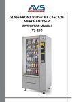
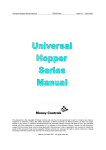
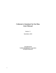
V21 Parts & Service Manual
All V21 Identified Equipment
MAINTENANCE
V21 Maintenance | M-1
REV A – 10/2013
P/N: 1230468
V21 Parts & Service Manual
All V21 Identified Equipment
REV A – 10/2013
P/N: 1230468
MAINTENANCE
The following section is a basic guide for general maintenance and servicing of the vendor. This
section is divided into three parts: (I) Preventative Maintenance, (II) Lubrication Guide, and (III)
Care and Cleaning.
I.
PREVENTATIVE MAINTENANCE SUGGESTIONS:
Whenever a vendor is visited on its site, the following service should be performed.
Preventative maintenance will help prevent future problems with the vendor.
A. Observe the vendor and its surrounding area for any unusual indications of
problems (rear of cabinet, obstructions of the air flow, dark spots on the sign
face, etc.).
B. Open the door and visually check the inside of the vendor (water accumulation,
rust marks, moisture around the edges of the inner door, etc.).
C. Check the fluorescent lamps, replace as necessary. Replace all lamps within 24 to
48 hours of burnout. This will prevent damage to the ballast.
D. Check the product temperature for proper cooling.
E. Check the evaporator drain for obstruction; water in the evaporator area must
drain to the condensation pan.
F. Empty condensation pan.
G. Clean the condenser filter.
H. Check that evaporator fan runs normally.
I. Check that the compressor and condenser fan run normally.
J. Investigate any unusual sounds (fan blades hitting something, refrigeration lines
rattling, etc.).
K. Clean coin acceptor.
L. Check for proper operation of the coinage mechanism by inserting all
denominations of coins accepted by the vendor.
M. Test the vendor and make a report on the problems.
II.
LUBRICATION GUIDE:
Lubricate indicated areas as directed on the chart below.
INTERVALS
PARTS
Every six months
Top door hinge, hinge pin at the base of cabinet,
door latch cam to cabinet strike, T-handle shaft &
latch.
As necessary
Pivot area of bucket and gate
V21 Maintenance | M-2
LUBRICANT
Grade two, high low
temperature grease
Grade two, high low
temperature grease
V21 Parts & Service Manual
All V21 Identified Equipment
III.
REV A – 10/2013
P/N: 1230468
CARE AND CLEANING:
DO NOT USE WATER JET FOR CLEANING.
AVOID USING WATER OR ANY OTHER LIQUIDS NEAR ELECTRONIC
COMPONENTS
A. GENERAL PROCEDURE (painted metal areas)
Wash the vendor with soap and water. The exterior may be waxed with any good
automobile wax.
B. FRESH PAINT SPLASHES, GREASE, GLAZING COMPOUND REMOVAL
Before drying, these elements may be removed by rubbing lightly with grade “A”
Naptha (or equivalent grade solvent). After removal, use general cleaning
procedure (listed above in A).
C. LABELS AND STICKER REMOVAL
Use any specialized label removal liquid. When the label material does not allow
penetration of solvent (such as vinyl), the application of heat (ie – hot air gun) will
soften the adhesive and promote removal. CAUTION: Excessive heat can cause
surface damage. After the label is removed, use the general cleaning procedure
(listed above in A).
D. SCRATCH REMOVAL
Remove or minimize hairline scratches and minor abrasions by using any good
quality automobile polish. Test product before using.
E. LEXAN SIGNS
To clean Lexan sign faces the following procedure is recommended.
A. Wash sign with mild soap or detergent and lukewarm water.
B. Using a soft cloth or sponge, gently wash the sign. DO NOT SCRUB!
C. Rinse well with clean lukewarm water.
D. Dry thoroughly with a chamois or cellulose sponge (to prevent water
spotting). DO NOT USE SQUEEGEE!
NOTE: Most organic solvents, petroleum, spirits, or alcohol are NOT
compatible cleaning materials for Lexan signs. Usage of those materials
could permanently damage the sign.
F. REFRIGERATION AREA
The condenser and evaporator must be kept clean for efficient operation. Be sure
all vanes and tubing are clean and clear of obstruction; this allows free passage of
air. Clean with a brush, a vacuum cleaner or compressed air, using extreme
caution not to bend the condenser vanes. Keep cabinet drain open; clean as
necessary.
V21 Maintenance | M-3
V21 Parts & Service Manual
All V21 Identified Equipment
REV A – 10/2013
P/N: 1230468
REFRIGERATION OPERATION
The refrigeration operation section is divided into three areas: Basic Refrigeration Principle,
Detailed Vending Machine Refrigeration Cycle, and Parts Description.
BASIC REFRIGERATION PRINCIPLE
What a refrigeration system really accomplishes is the transfer of heat. A refrigeration system
removes the excess heat from a refrigerated area and then transfers it to a condenser where it is
dissipated. As heat is removed, the refrigerated area cools.
In vending machines, large quantities of the heat must be transferred rapidly, economically and
efficiently. This process must be able to withstand continuous repetition, without loss of
refrigerant, over an extended period. The most common system used in the vending industry is
the vapor compression (or simple compression) cycle system. It consists of four basic elements:
An evaporator, a compressor, a condenser, and a pressure-reducing device (all part of a sealed
system).
The compression system operates at two pressure levels: The low evaporating pressure and the
high condensing pressure. The refrigerant acts as the transport medium, in which heat is moved
from the evaporator to the condenser; at the condenser, the heat is dissipated into the
surrounding air.
The liquid refrigerant changes from a liquid to a vapor and back to a liquid again. This change of
state allows the refrigerant to absorb, and rapidly discharge, large quantities of heat efficiently.
BASIC VAPOR COMPRESSION SYSTEM CYCLE:
In the evaporator, the liquid refrigerant vaporizes. This change occurs at a temperature low
enough to absorb heat from the refrigerated space. The temperature of vaporization is
controlled by the pressure maintained in the evaporator (the higher the pressure, the higher the
vaporization point).
The compressor pumps the vapor from the evaporator, through the suction line, and to the
condenser. The compressor takes the low pressure vapor and compresses it, increasing both the
pressure and the temperature. The compressor pumps the vapor at a rate rapid enough to
maintain the ideal pressure. The hot, high pressure vapor is forced out of the compressor, into
the discharge line and then into the condenser.
Air is blown through the condenser, allowing heat to transfer from the condenser and into the
passing air. As the heat is removed, the stored refrigerant is condensed into a liquid. The liquid
refrigerant is stored in the lower tube of the condenser. This is where it flows through the
capillary tube back into the evaporator, where the refrigeration cycle is repeated.
V21 Maintenance | M-4
V21 Parts & Service Manual
All V21 Identified Equipment
REV A – 10/2013
P/N: 1230468
DETAILED REFRIGERATION CYCLE
The following is a detailed refrigeration cycle as it applies to the refrigeration system installed in
SandenVendo America, Inc. equipment. (Refer to the flow chart in Figure 1.)
As the air temperature in the cabinet rises, the electronic temperature sensor reports the air
temperature to the electronic controller. The electronic controller actuates the refrigeration
control relay, which turns on both the compressor and condenser fan motor.
The evaporator fan pulls air from the front of the refrigerated space of the cabinet. It pulls the
air through the evaporator, and blows it up the rear of the vend stack. (The evaporator fan runs
continuously.) As the air passes through the evaporator, heat is drawn from the air and
transferred to the liquid refrigerant. As the cooled air circulates through the vend stack, heat is
drawn from the product and transferred to the circulating air. The heated air is again drawn
through the evaporator where the heat is removed.
In the evaporator, the liquid refrigerant draws heat from the circulating air. As refrigerant
receives heat, it vaporizes.
The compressor pumps the vapor from the evaporator and compresses it, increasing both
pressure and temperature. The compressor forces the compressed vapor out, through the
discharge line and into the condenser.
The condenser fan pulls air through the condenser. As the hot refrigerant vapor passes through
the condenser tubes, heat is drawn from the vapor. This heat is dissipated into the passing air.
The air then exits out the back of the vendor. As the refrigerant vapor in the condenser lines is
cooled, it returns to a liquid state.
From the condenser the liquid flows to the drier. The drier removes any water and solid particles
from the liquid refrigerant.
The cooled liquid refrigerant continues from the drier, through the capillary tube, to the
evaporator. The capillary tube steadies the flow rate of the refrigerant. Its small inside diameter
allows the pressure in the evaporator to remain low while the pressure in the condenser is high.
The cool refrigerant in the evaporator draws heat from the circulating air in the cabinet. As the
temperature in the cabinet drops, the electronic temperature sensor reports the air temperature
to the electronic controller. The electronic controller deactivates the refrigeration control relay,
which turns off the compressor and condenser fan motor.
When the air temperature in the cabinet rises above the electronic controller’s cut in setting, the
compressor and the condenser fan engage again.
V21 Maintenance | M-5
V21 Parts & Service Manual
All V21 Identified Equipment
V21 Maintenance | M-6
REV A – 10/2013
P/N: 1230468
V21 Parts & Service Manual
All V21 Identified Equipment
REV A – 10/2013
P/N: 1230468
REFRIGERATION PARTS DESCRIPTION
The compressor, condenser, drier, capillary tube, evaporator, and accumulator are part of a
sealed system (refer to Figure 2). These items are not available separately.
COMPRESSOR
The compressor takes in low pressure vapor and compresses it, increasing both the pressure and
the temperature. The hot, high pressure gas is forced out to the condenser. The compressor and
the motor that drives the compressor are sealed inside a housing. The compressor, as a unit, is
mounted on the refrigeration base. The base is mounted in the bottom of the vendor, outside
the sealed refrigeration space.
CONDENSER
The condenser takes heat out of the high pressure vapor that it receives from the compressor.
As the vapor passes through the condenser it cools and returns to a liquid state. The condenser
is mounted to the refrigeration base near the front of the vendor. It is easily accessible for
cleaning.
DRIER
The drier is a molecular sieve strainer drier. It removes water and solid particles from refrigerant
liquid. One side of the drier is connected to the outlet line of the condenser; the other side is
connected to the capillary tube going to the evaporator.
CAPILLARY TUBE
The capillary tube controls, at a steady rate, the flow of refrigerant liquid to the evaporator. It
has a very small inside diameter to keep pressure in the evaporator low while the pressure in the
condenser is high. It is the connecting link between the condenser and evaporator.
EVAPORATOR
The evaporator is a heat transference device. It removes the heat from the air in a refrigerated
space and transfers it to the refrigerant liquid. This liquid evaporates into a vapor and is
removed by the compressor. The evaporator is mounted inside the refrigerated space of the
cabinet, directly below the delivery chute.
ACCUMULATOR
The accumulator traps any refrigerant liquid, which did not boil off into a vapor before reaching
the compressor. The accumulator allows the refrigerant liquid to boil off as a vapor (preventing
damage to the compressor). It also prevents suction line sweating. The accumulator is mounted
in the suction line on the outline side of the evaporator.
V21 Maintenance | M-7
V21 Parts & Service Manual
All V21 Identified Equipment
V21 Maintenance | M-8
REV A – 10/2013
P/N: 1230468
V21 Parts & Service Manual
All V21 Identified Equipment
REV A – 10/2013
P/N: 1230468
The parts listed below are not part of the sealed refrigeration system and are available
separately.
START CAPACITOR - P/N
CHAMELEON: 1112805
TRADE: 1112805
HV3: 1124549
HVV: 1124549
The start capacitor is used to increase power during the start. This additional power will
help get the compressor running in case there is any back pressure.
STARTING RELAY – INCLUDED IN ASSEMBLY P/N
CHAMELEON: 513506066
TRADE: 513506066
HV3: 513506066
HVV: 513506066
The starting relay is mounted in the terminal box on the outside of the compressor
under the housing. When the compressor first starts up, the starting relay closes and
completes a starting circuit. When the compressor motor reaches operating speed, the
starting relay opens and breaks the starting circuit.
THERMAL OVERLOAD SWITCH – INCLUDED IN ASSEMBLY P/N
CHAMELEON: 513506066
TRADE: 513506066
HV3: 513506066
HVV: 513506066
The thermal overload switch is mounted in the terminal box on the outside of the
compressor under the housing. If the compressor motor gets hot or draws too much
current, the thermal overload opens and breaks the starting and running circuit of the
motor. As the motor cools, the thermal overload closes, allowing the compressor to
restart.
TEMPERATURE SENSOR – P/N
CHAMELEON: 1122924
TRADE: 1122924
HV3: 1122924
HVV: 1122924
The temperature sensor is mounted in the inlet airflow of the evaporator. This monitors
the air temperature and reports it to the electronic controller so that the controller can
operate the refrigeration system via the power box.
V21 Maintenance | M-9