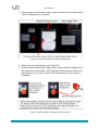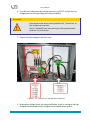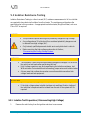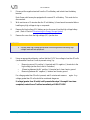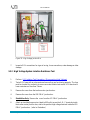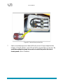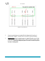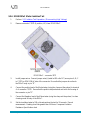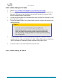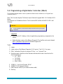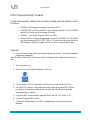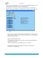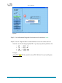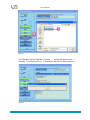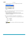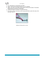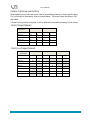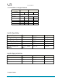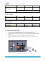
1
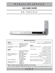
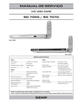
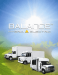
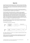
Service Manual
9 Special Procedures
9.1
Securing a Damaged Hybrid Vehicle .......................................................................195
9.2
Disconnecting the Energy Storage System ..............................................................196
9.3
Isolation Resistance Testing ......................................................................................202
9.4
Programming a Digital Motor Controller (DMoC) ................................................218
9.6
Fastener Tightening Procedure ................................................................................227
9.7
ESS Fuse Replacement ..............................................................................................231
Note 1: Additional procedures that are not covered in this manual may be found on the Product
Support Extranet https://extranet.azuredynamics.com
Note 2: Before servicing any high-voltage component, the ESS must be disabled as per the
instructions in this Section: Disconnecting the Energy Storage System.
Furthermore, once the ESS is disconnected, the voltage must be checked across the positive and
negative terminals in the high voltage junction box and must be less than 1 volt.
DANGER
•
This procedure requires working with potentially dangerous high voltage.
•
Any voltage above 30 volts should be considered potentially dangerous and
is referred to as high voltage (HV).
•
•
Only trained, qualified personnel should service a hybrid-electric vehicle.
Disconnect the Energy Storage System ( ESS) before servicing the highvoltage system
Azure Dynamics Balance Hybrid-electric Vehicle – 2008/ 2009/ 2010 Ford E-450
194
Service Manual
9.1 Securing a Damaged Hybrid Vehicle
Disable the vehicle and its high-voltage electrical system by performing as many of these steps
as possible.
1) Put the shift lever into Park.
2) Remove the ignition key. Removing the ignition key or turning it to the “OFF” position
will disconnect the high voltage system, unless the battery is damaged.
3) Block the wheels if necessary.
4) Disconnect the negative cable (black) from the 12 volt battery; it is located in the engine
compartment – this will also disconnect the high voltage circuit.
5) Disconnect the low voltage connector from front of the battery pack. Turn counter clockwise (¼ turn) and pull it out.
6) If the battery is not accessible, remove or cut the low voltage cable (connected to the
vehicle interface connector . Do not cut the high voltage (orange) cable.
WARNING
•
If the high voltage battery pack was damaged physically or electronically
during an accident, there is a possibility that high voltage may still be present
on the orange cables even after the 12 volt battery is disconnected.
•
Always follow high voltage training.
Azure Dynamics Balance Hybrid-electric Vehicle – 2008/ 2009/ 2010 Ford E-450
195
Service Manual
9.2 Disconnecting the Energy Storage System
Warning
Always remember to consult the safety section (Section 1) before servicing any
Hybrid Component.
WARNING
The electrical system in this vehicle is capable of producing lethal voltage
levels.
All drivetrain and control systems must be maintained and serviced by trained
personnel, who are qualified to service Azure hybrid vehicle systems.
The ESS (HV Battery) must be properly disconnected before opening any high voltage
component, enclosure, or contacting any high voltage wiring. Various components in the hybrid
system contain capacitors that store high voltage charges.
Always wait a minimum of 5 minutes after the key has been turned off and removed from the
vehicle before disconnecting or exposing any high voltage cable or component.
Once the ESS (HV battery) service disconnect has been removed, a multimeter (high voltage
rated) must be used to verify that there is no voltage present.
Removing the ESS (HV Battery) involves contact with potential deadly voltages. All safety
procedures MUST be followed to prevent the possibility of an electrical shock.
When working on the ESS (HV Battery), the keys to the vehicle should be in the possession of
the technician. The keys should NOT be left in the ignition.
Use proper lifting equipment as the ESS (HV Battery) is heavy.
Azure Dynamics Balance Hybrid-electric Vehicle – 2008/ 2009/ 2010 Ford E-450
196
Service Manual
Figure 63: High Voltage Battery Pack
Tools
•
Multimeter (Rated for a working voltage of at least 500 volts DC)
•
A multi-meter and proper test leads suitable for use with the high voltages involved in
this system is a required piece of safety equipment as well as for diagnostics. Circuits
must be checked for high voltage before making contact with any terminal or junction.
Meters must be rated for a minimum of 600 volts.
•
Electrical safety gloves (Rated for a working voltage of at least 500V, i.e. ASTM class 00
or better)
Procedure
1. Turn the ignition key OFF and remove the key from the ignition.
2. Always wait a minimum of 5 minutes after the key has been turned off and removed from
the vehicle before disconnecting or exposing any high voltage cable or component.
3. Clean the front of the battery pack around the LV connector C053S, and the service
disconnect covers to remove dirt and debris.
4. Remove the low voltage connector C053S from the front of the battery pack by turning
counter clockwise approximately ¼ turn
Azure Dynamics Balance Hybrid-electric Vehicle – 2008/ 2009/ 2010 Ford E-450
197
Service Manual
Figure 34: Removing the LV connector from ESS (HV Battery)
WARNING
Removing the high voltage service disconnect pin cuts off high
voltage from the vehicle, but the individual cells inside the ESS will
remain charged.
Do not cut into the high voltage ESS case, or penetrate the ESS in any
way.
Always assume the ESS and all high voltage components may still be
electrically active, until it is verified that there is no voltage.
Azure Dynamics Balance Hybrid-electric Vehicle – 2008/ 2009/ 2010 Ford E-450
198
Service Manual
1. Using a 4mm hex driver, remove the 6 service disconnect cover screws from the
front of the battery pack. (Figure 60).
Figure 60: Service disconnect cover and attaching screws
2. Remove the service disconnect cover (Figure 60)
3. While wearing insulated High Voltage gloves, remove the high voltage service
disconnect pin from the battery. While applying inward pressure to the service
disconnect pin, turn it ¼ turn counter clockwise, and then pull it out (refer to
illustration).
Figure 61: Removing high voltage service disconnect pin
Azure Dynamics Balance Hybrid-electric Vehicle – 2008/ 2009/ 2010 Ford E-450
199
Service Manual
4. Once the service disconnect pin has been removed, you MUST verify there is no
voltage present on the high voltage bus before proceeding.
WARNING
Use extreme caution when working inside the HV Junction box, as
high voltage may be present.
Use HV Insulated Gloves when working or taking measurements
inside the HV Junction box.
5. Remove the high voltage junction box cover.
Figure 61: HV Junction Box Terminals and Connections
6. Wearing high voltage gloves, and using a multimeter, check for voltage on the high
voltage bus and between the high voltage bus and isolated chassis ground:
Azure Dynamics Balance Hybrid-electric Vehicle – 2008/ 2009/ 2010 Ford E-450
200
Service Manual
a) Across the HV positive (+) and HV negative (-) junction box studs (circled in
green (refer to illustration)).
b) Between the HV positive (+) junction box stud and chassis ground.
c) Between the HV negative (-) junction box stud and chassis ground.
If the voltage is less than 5 volts, it is now safe to continue. If there is more than 5
volts, wait a few minutes for the voltage to dissipate and recheck. If the voltage is still
greater than 5 volts, refer to the service manual for further diagnosis.
WARNING
This procedure confirms the absence of voltage only at the main
junction box studs. If a HV junction box fuse has blown, there is a
possibility that a capacitor could remain charged on an individual
circuit downstream of the fuse, and have HV present. When handling
any individual circuit, the absence of voltage on that circuit should be
verified.
Azure Dynamics Balance Hybrid-electric Vehicle – 2008/ 2009/ 2010 Ford E-450
201
Service Manual
9.3 Isolation Resistance Testing
Isolation Resistance Testing is a direct current (DC) resistance measurement of all circuits that
are required to have electrical isolation from the chassis. The resistance must be above the
specified value in this procedure. An appropriate insulation tester (MegOhm Meter) such as a
Fluke 1507 is required.
DANGER
•
This procedure requires working with potentially dangerous high voltage.
•
Any voltage above 30 volts should be considered potentially dangerous and
is referred to as high voltage (HV).
•
Only trained, qualified personnel should service a hybrid-electric vehicle.
•
Before servicing the high-voltage system refer to Section;
Disconnecting the Energy Storage System.
WARNING
•
•
•
The Insulation Tester can produce potentially dangerous voltages. Do not touch
the vehicle or test leads when performing this test.
High Voltage capacitors may be charged during the isolation resistance test.
Wait minimum 5 minutes before disconnecting jumper wires and isolation tester.
Always wear high voltage gloves when connecting and disconnecting high
voltage leads and test equipment.
IMPORTANT
•
•
Care must be taken to follow the procedure below to get accurate results.
If the high voltage system isolation test does not meet specification, testing of
the individual components while isolated from the rest of the system will be
required.
9.3.1 Isolation Test Preperation ( Disconnecting High Voltage)
1.
Remove the vehicle key from the ignition and store in secure area.
Azure Dynamics Balance Hybrid-electric Vehicle – 2008/ 2009/ 2010 Ford E-450
202
Service Manual
2.
3.
Disconnect the negative terminal from the 12 volt battery and isolate from the battery
terminal.
Note: Some vehicles may be equipped with a second 12 volt battery. This must also be
disconnected.
Wait a minimum of 5 minutes after the 12 volt battery (s) have been disconnected before
handling any high voltage wiring or component.
4.
Remove the high voltage (HV) battery service disconnect from the high voltage battery
pack. (Refer to Section Disconnecting the Energy Storage System)
5.
Remove the cover from the high voltage (HV) junction box.
WARNING
•
6.
Always wear high voltage gloves when connecting and disconnecting high
voltage leads and test equipment.
Using an appropriate voltmeter, confirm that the HV DC bus voltage is less than 30 volts
(recommended less than 5 volts to prevent arcing) by:
o
o
o
Measuring across HV positive (+) terminal and HV negative (-) terminals in the
high voltage junction box (refer to illustration).
Measuring between the HV positive (+) terminal and clean chassis ground.
Measuring between HV negative (-) terminal and chassis ground.
If a voltage greater than 30 volts is present, wait 5 minutes and measure
voltage greater than 30 volts should be considered dangerous.
again. Any
If voltage (greater than 30 volts) is still present after steps 1 through 6 have been
completed, contact Azure Techline immediately at 1-866-473-1636
Azure Dynamics Balance Hybrid-electric Vehicle – 2008/ 2009/ 2010 Ford E-450
203
Service Manual
Figure 35: High Voltage Junction Box
7.
Inspect all HV connections for signs of arcing, loose connections, water damage or other
damage.
9.3.2 High Voltage System Isolation Resistance Test
1.
Perform 9.3.1 Isolation Test Preparation ( Disconnecting High Voltage)
2.
Test all HV fuses with an ohm meter and ensure they are functioning properly. The fuse
must be checked for continuity to ensure accurate isolation test results. All fuses should
have a resistance of less than 5 ohms.
3.
Remove the cover from the traction motor junction box.
4.
Remove the cover from the ISG DMoC junction box.
5.
Shuttle Bus Only- Remove the cover from the AC DMoC junction box
6.
Attach an insulated jumper wire (rated to 600 volts) across the A, B, C terminals inside
the traction motor junction box, and to the positive high voltage terminal inside the ISG
DMoC junction box. (refer to illustration)
Azure Dynamics Balance Hybrid-electric Vehicle – 2008/ 2009/ 2010 Ford E-450
204
Service Manual
Figure 36: Traction Motor Junction Box
7.
Attach an insulated jumper wire (rated to 600 volts) across all 5 high voltage terminals
RT048-A, RT049-B, RT050-C, and RT071 & RT072 in the ISG DMoC junction box. To
avoid false readings the jumper wires must not contact the junction box case or
chassis ground. (refer to illustration)
Azure Dynamics Balance Hybrid-electric Vehicle – 2008/ 2009/ 2010 Ford E-450
205
Service Manual
Figure 37- ISG Junction Box
8.
Connect an insulated jumper wire (rated to 600 volts) between the HV positive (+)
terminal and HV negative (-) terminal in the HV junction box (refer to illustration).
9.
Shuttle Bus Only- Attach an insulated jumper wire (rated to 600 volts) across all 5 high
voltage terminals RT048-A, RT049-B, RT050-C, and RT071 & RT072 in the AC DMoC
junction box. To avoid false readings the jumper wires must not contact the junction
box case or chassis ground..
Azure Dynamics Balance Hybrid-electric Vehicle – 2008/ 2009/ 2010 Ford E-450
206
Service Manual
Figure 38- AC DMoC Junction Box
10.
Connect the negative lead of the insulation tester (using the clamp not the probes) to a
chassis ground point where a ground strap is connected. Make sure that any paint is
removed from chassis at ground location.
11.
Connect the positive lead of the isolation tester (using the clamp not the probes) to the
HV positive (+) terminal inside the HV junction box. (refer to illustration).
Azure Dynamics Balance Hybrid-electric Vehicle – 2008/ 2009/ 2010 Ford E-450
207
Service Manual
Figure 39: Isolation Testing Connection Diagram
WARNING
•
•
•
The Insulation Tester can produce potentially dangerous voltages. Do not touch
the vehicle or test leads when performing this test.
High Voltage capacitors may be charged during the isolation resistance test.
Wait minimum 5 minutes before disconnecting jumper wires and isolation tester.
Always wear high voltage gloves when connecting and disconnecting high
voltage leads and test equipment.
Azure Dynamics Balance Hybrid-electric Vehicle – 2008/ 2009/ 2010 Ford E-450
208
Service Manual
12.
Set the insulation tester to 500 volts and perform the test for 30 seconds or until the
reading stabilizes and record measurement. (HV Positive (+) Stud Measurement). The
resistance value should be greater than 1 Mohm. If less than 1 Mohm then each
individual component will need to be isolated from the system by disconnecting the
high voltage leads to that component and following the procedures for that given
component outlined in sections 9.3.3, 9.3.4, 9.3.5, 9.3.6 or 9.3.7.
13.
When the voltage reading on the insulation tester has decreased to less than 30 volts,
remove the insulation tester test leads and all jumper wires. If your insulation tester does
not read voltage, use a voltmeter to ensure there is less than 30 volts present before
removing any test leads or jumper wires.
14.
Remove connector C337P (4 position, HV) from EPAS DMoC.
Figure 39: EPAS DMOC Connectors
15.
Install an insulated jumper wire (rated to 600 volts) across pins A, B, C in C337P.
Ensure that the jumper wire does not touch the DMoC body or pin “D”.
16.
Connect the positive lead of the insulation tester (using the clamp not the probes) to
terminal A of connector C337P. Ensure that the positive test leads do not touch the
housing of the connector or pin ”D”.
17.
Connect the negative lead of the insulation tester (using the clamp not the probes) to a
chassis ground point where a ground strap is connected, or to the body of the EPAS
Motor. Make sure that any paint is removed from chassis at ground location.
Azure Dynamics Balance Hybrid-electric Vehicle – 2008/ 2009/ 2010 Ford E-450
209
Service Manual
18.
Set the insulation tester to 500 volts and perform the test for 30 seconds, or until the
reading stabilizes. Record the measurement (EPAS Motor (AC) Measurement).
Note: The resistance value should be greater than 10 Mohm. If less than 10Mohm
replace the EPAS motor.
19.
When the voltage reading on the insulation tester has decreased to less than 30 volts,
remove the insulation tester test leads and all jumper wires. If your insulation tester does
not read voltage, use a voltmeter to ensure there is less than 30 volts present before
removing any test leads or jumper wires.
20.
Connect C337P to EPAS DMoC.
21.
Install the ISG DMoC junction box cover.
22.
Install the traction motor junction box cover.
23.
Install the HV junction box cover.
24.
Install the high voltage battery service disconnect pin and the cover to battery pack.
25.
Reconnect the 12 volt battery(s).
26.
Return the vehicle key to the ignition.
27.
Start the vehicle and verify the correct operation of the hybrid system.
Component
Test
Voltage
Minimum Isolation Resistance (Mohm’s)
after 60 seconds
Complete system as measured from the High
Voltage Junction Box
Traction Motor
Traction Motor Controller (DMoC SI)
ISG Motor
ISG Motor Controller ( DMoC 445)
EPAS Motor (Satcon)
EPAS Motor Controller ( DMoC 145)
High Voltage Cabling when isolated from the high
voltage bus.
Cobasys Battery
500 volts
greater than 1 Mohms
500 volts
500 volts
500 volts
500 volts
500 volts
500 volts
500 volts
greater than 10 Mohms
greater than 4 Mohms
greater than 10 Mohms
greater than 4 Mohms
greater than 10 Mohms
greater than 4 Mohms
greater than 10 Mohms
280-330
volts
Note- the ESS performs it’s own isolation
resistance diagnostic at each key on cycle
and also monitors the isolation during
normal Hybrid operation. No additional
testing is required.
Greater than2 Mohms at initial Key on
not cranked, greater than 500 Kohms
running in HV mode as reported by
diagnostic tool
Table 5: Component Isolation Resistance Specification
Azure Dynamics Balance Hybrid-electric Vehicle – 2008/ 2009/ 2010 Ford E-450
210
Service Manual
9.3.3 EPAS Motor Isolation Testing
1.
Perform 9.3.1 Isolation Test Preparation ( Disconnecting High Voltage)
2.
Remove connector C337P (4 position, HV) from EPAS DMoC
Figure 40: EPAS DMOC Connectors
Azure Dynamics Balance Hybrid-electric Vehicle – 2008/ 2009/ 2010 Ford E-450
211
Service Manual
3.
Install jumper wires across pins A, B, C in C337P. Ensure that the jumpers do not touch
the DMoC body or pin “D
4.
Connect the positive lead of the Insulation Tester (using the clamp not the probes) to
terminal A of connector C337P. Ensure that the positive test probe does not touch the
housing of the connector or pin ”D”.
5.
Connect the negative lead of the Insulation Tester (using the clamp not the probes) to a
chassis ground point where a ground strap is connected or to the body of the EPAS
Motor. Make sure that any paint is removed from chassis at ground location.
6.
Set the Insulation Tester to 500 volts and perform the test for 30 seconds or until the
reading stabilizes. Record measurement (EPAS Motor (AC) Measurement)
Note: The resistance value should be greater than 10 Mohm. If less than 10Mohm
replace the EPAS motor.
7.
Remove the Insulation Tester and jumper wires
8.
Connect C337P to EPAS DMoC.
9.
Install the cover to access panel at the ISG DMoC.
10.
Install the cover to access panel at the traction DMoC
11.
Install the cover to the high voltage junction box.
12.
Install the high voltage battery service disconnect pin and the cover to battery pack.
13.
Reconnect the 12 volt batteries
14.
Return vehicle key to the ignition.
9.3.4 ISG DMoC Isolation Test
1.
2.
Perform 9.3.1 Isolation Test Preparation ( Disconnecting High Voltage)
Remove all high voltage wires RT048-A, RT049-B, RT050-C, RT071 and RT072 from
the DMoC at the access panel.
3.
With the DMoC high voltage wiring disconnected from the rest of the vehicle, connect
a jumper wire (rated to 600V) across all terminals in the ISG access panel from RT048-A
to RT049-B to RT050-C to RT071 to RT072
Azure Dynamics Balance Hybrid-electric Vehicle – 2008/ 2009/ 2010 Ford E-450
212
Service Manual
4.
Connect the positive lead of the insulation tester (using the clamp not the probes) to the
RT071 + connection in the access panel.
5.
Connect the negative lead of the insulation tester (using the clamp not the probes) to the
DMoC body or ground lug.
WARNING
•
•
•
The insulation tester can produce potentially dangerous voltages. Do
not touch the vehicle or test leads when performing this test.
High Voltage capacitors may be charged during the insulation test.
Wait 5 min before disconnecting jumper wires and isolation tester.
Always wear high voltage gloves when connecting and disconnecting
high voltage leads.
6.
Set the insulation tester to 500 volts and perform the test for 30 seconds. Record
measurement and compare to the motor ISG controller resistance. (refer to illustration)
7.
Replace the ISG DMoC if it is less than4 Mohms.
9.3.5 ISG Motor Isolation Test
1.
2.
3.
4.
5.
Perform 9.3.1 Isolation Test Preparation ( Disconnecting High Voltage)
Disconnect C302S at the ISG motor.
Connect jumper wire(s) (rated to 600 volts DC) across terminals A, B and C of C302p
(motor side).
Connect the positive lead of the insulation tester (using the clamp not the probes) to the
terminal A connection.
Connect the negative lead of the insulation tester (using the clamp not the probes) to the
ISG motor body.
Azure Dynamics Balance Hybrid-electric Vehicle – 2008/ 2009/ 2010 Ford E-450
213
Service Manual
WARNING
•
•
•
6.
7.
The insulation tester can produce potentially dangerous voltages. Do
not touch the vehicle or test leads when performing this test.
High Voltage capacitors may be charged during the insulation test.
Wait 5 min before disconnecting jumper wires and isolation tester.
Always wear high voltage gloves when connecting and disconnecting
high voltage leads.
Set the insulation tester to 500 volts and perform the test for 30 seconds. Record
measurement and compare to ISG DMoC in the Component Isolation Resistance
Specification chart
Replace the ISG Motor if it is less than10 Mohms.
Azure Dynamics Balance Hybrid-electric Vehicle – 2008/ 2009/ 2010 Ford E-450
214
Service Manual
9.3.6 EPAS DMoC Motor Isolation Test
1.
Perform 9.3.1 Isolation Test Preparation ( Disconnecting High Voltage)
2.
Remove connector C337P (4 position, HV) from EPAS DMoC.
EPAS DMoC – connector 337P
3.
Install jumper wires- Connect jumper wire(s) (rated to 600 volts DC) across pins A, B, C
in C337S on EPAS DMoC side of the connector. Ensure that the jumpers do not touch
the DMoC body or pin “D”.
4.
Connect the positive lead of the Mohm tester (using the clamp not the probes) to terminal
A of connector C337S. Ensure that the positive test probe does not touch the housing of
the connector or pin”D”.
5.
Connect the Negative lead of the Mohm tester (using the clamp not the probes) to clean
chassis ground or body of the DMoC.
8.
Set the insulation tester to 500 volts and perform the test for 30 seconds. Record
measurement. Reading should be greater than 4 Mohms. Component Isolation
Resistance Specification chart
Azure Dynamics Balance Hybrid-electric Vehicle – 2008/ 2009/ 2010 Ford E-450
215
Service Manual
6.
WARNING
•
•
•
The insulation tester can produce potentially dangerous voltages. Do
not touch the vehicle or test leads when performing this test.
High Voltage capacitors may be charged during the insulation test.
Wait 5 min before disconnecting jumper wires and isolation tester.
Always wear high voltage gloves when connecting and disconnecting
high voltage leads.
9.3.7 ISG HV WIRING – ISG motor to DMoC
1.
2.
3.
4.
5.
6.
Perform 9.3.1 Isolation Test Preparation ( Disconnecting High Voltage)
Disconnect the positive RT048-A, RT049-B, RT050-C leads from the junction box.
Disconnect C302S from ISG motor.
Install jumper wires across RT048-A, RT049-B, RT050-C ( cable Side)
Connect the positive lead of the insulation tester (using the clamp not the probes) to
RT048
Connect the negative lead of the insulation tester (using the clamp not the probes) to the
chassis ground lug.
WARNING
•
•
•
9.
7.
The insulation tester can produce potentially dangerous voltages. Do
not touch the vehicle or test leads when performing this test.
High Voltage capacitors may be charged during the insulation test.
Wait 5 min before disconnecting jumper wires and isolation tester.
Always wear high voltage gloves when connecting and disconnecting
high voltage leads.
Set the insulation tester to 500 volts and perform the test for 30 seconds. Record
measurement and compare to table above for EPAS DMoC resistance. Component
Isolation Resistance Specification chart.
Replace the ISG motor high voltage cable if it is less than10 Mohms
Azure Dynamics Balance Hybrid-electric Vehicle – 2008/ 2009/ 2010 Ford E-450
216
Service Manual
9.3.8 Isolation testing a HV Cable
1.
2.
3.
4.
Perform 9.3.1 Isolation Test Preparation ( Disconnecting High Voltage)
Disconnect the conductor proton of the cable form the component (s) it connects to on
both ends. Make sure to leave the gland nuts secured to the vehicle component so the
shield is connected to the Chassis ground.
Connect the positive lead of the insulation tester (using the clamp not the probes) to one
end of the cable conductor
Connect the negative lead of the insulation tester (using the clamp not the probes) to the
chassis ground lug.
WARNING
•
•
•
5.
6.
The insulation tester can produce potentially dangerous voltages. Do not
touch the vehicle or test leads when performing this test.
High Voltage capacitors may be charged during the insulation test.
Wait 5 min before disconnecting jumper wires and isolation tester.
Always wear high voltage gloves when connecting and disconnecting
high voltage leads.
Set the insulation tester to 500 volts and perform the test for 30 seconds. Record
measurement and compare to table above for High Voltage Cabling when isolated from
the high voltage bus. Component Isolation Resistance Specification chart.
If resistance value is less than 10 Mohm, Replace the cable.
9.3.9 Isolation testing AC DMoC
Azure Dynamics Balance Hybrid-electric Vehicle – 2008/ 2009/ 2010 Ford E-450
217
Service Manual
9.4 Programming a Digital Motor Controller (DMoC)
This procedure provides details to load or update the software and/or calibrations on a Digital Motor
Controller (DMOC).
Note: This Procedure Applies To Balance Hybrid Vehicles Equipped With VCU Software R4 Or
Newer.
The Software And Calibrations Used In This Procedure Will Not Work With R2 Or R3 Level
Software!
WARNING
Always remember to consult the vehicle safety section before servicing any Hybrid
Component.
Important
•
Make sure the 12 V battery is fully charged before programming components in the
vehicle.
•
Obtain the latest version of the Balance Diagnostic Tool and the most recent released
DMoC calibrations from the Azure Extranet Support site.
https://extranet.azuredynamics.com
Tools
1. Laptop
2. Latest version of the Balance Diagnostic (Full Version) ,Tool V4_0_0 or newer
3. DMoC calibration files which consists of 3 files: *.ccs, *.ehx and *.par
4. Note the numeric identifiers in the filename indicates which motor controller the file
should be written to:
• A/C (3032)
• TM (3033)
• ISG (3034)
• EPAS (3035)
5.
6.
7.
8.
103460-A – Hrns Serial Program, DMoC
103298-D CAN diagnostic harness
DB9 Extension cable (9 pin communications cable)
Boot key
Azure Dynamics Balance Hybrid-electric Vehicle – 2008/ 2009/ 2010 Ford E-450
218
Service Manual
DMoC Reprogramming Procedure
Connect the diagnostic cables to the connectors located under the steering column
as follows:
•
103298-D CAN diagnostic harness to connector C073P
•
KVASER CAN to USB to 103298-D CAN diagnostic harness ( CAN 2/ C006BS)
and the USB end to one of the Laptop USB ports
•
103460-A – Hrns Serial Program, DMoC to C336S
•
Connect DB9 ext. cable to the appropriate connection on103460 –A for the DMoC
you are programming (EPAS, MPT, ISG or AC) and connect the other end of the
DB9 extension cable to the laptop RS-232 port (9 pin communications port)
Important
•
Do not disconnect these cables during the programming process. This may permanently
damage the components.
Note: Make Sure That Only The Programs That Are Required For Programming A Dmoc Are
Open.
1. Turn on ignition key
2. Double Click on the Balance Diagnostic Tool Icon.
3. Confirm that the CAN is connected to CAN 2 and then select the DMoCs Tab.
4. Go to the DTCs and Info Codes page and confirm there are no stored DTCs before
proceeding. If codes are stored then save the faults for reference and retest after
reprogramming is complete.
5. From the DMoC screen select the required DMoC tab: TM, ISG, EPAS or AC.
6. Click the Program DMoC button
7.
There are 8 defined steps in the DMoC reprogramming software that need to be
followed:
Azure Dynamics Balance Hybrid-electric Vehicle – 2008/ 2009/ 2010 Ford E-450
219
Service Manual
Step 1- check the “Using Boot Key “ tab “yes” if boot key is installed in the DMoC or “No”
if programming without Bootkey. (Refer to illustration detail “A”)
Note: Boot Key Is Only Necessary If Programming Fails Midway In The First Attempt.
Step 2- Check the box for the DMoC you are connected to. (Refer to illustration detail “B”)
Figure 41
Step 3- Click the “Connect to Vehicle” (Refer to illustration detail “C”) button and it will
turn Green when connected. If button turns Red, verify that key is on and the diagnostic
cables are connected correctly.
Step 4- ISG and EPAS DMoCs OnlyClick the Enable High Voltage button. It may take several seconds for the Enable High
voltage button to turn green
Notes: Several Buttons May Turn Red Momentarily- This Is Normal.
The Diagnostic Tool Reprogramming Steps 4 & 8 Will Be Grayed Out And Not
Performed For TM Programming.
Azure Dynamics Balance Hybrid-electric Vehicle – 2008/ 2009/ 2010 Ford E-450
220
Service Manual
Figure 42
Step 5- Click the Extended Diagnostic Mode button and it should turn Green.
Step 6- Click the “Program DMoC” button and then click on the “Select .ehx File”
Select the .ehx file for the appropriate DMoC you are programming and then click
•
•
•
•
A/C ……3032…ehx
TM ……3033…ehx
ISG …….3034…ehx
EPAS …...3035…ehx
Example:
P1X-06PM-3035-000.ehx would be for an EPAS (Electric Power Assist System)
DMoC
Azure Dynamics Balance Hybrid-electric Vehicle – 2008/ 2009/ 2010 Ford E-450
221
Service Manual
Figure 43
The Calibration file will load and a “Success…..” window will pop up when
complete. Cycle the key off for ~ 10 seconds and then back to the on position.
Figure 44
Azure Dynamics Balance Hybrid-electric Vehicle – 2008/ 2009/ 2010 Ford E-450
222
Service Manual
A window with “Warning: Vehicle is not in diagnostics mode” will appear.
Click OK to continue.
Figure 45
Step 7- Click the “Enable High Voltage” button. It may take several seconds for the
“Enable High Voltage” button to turn green
Notes: Several Buttons May Turn Red Momentarily- This Is Normal.
The Diagnostic Tool Reprogramming Steps 4 & 8 Will Be Greyed Out And Not
Performed For TM Programming.
Step 8 –Click the “Calibrate DMoC” button and then “Load Parameter File”
Select the .par file for the appropriate DMoC you are programming and then click
“Open”
•
•
•
•
A/C ……3032…par
TM ……3033…par
ISG …….3034…par
EPAS …...3035…par
Example:
P1X-06PM-3035-000.par would be for an EPAS (Electric Power Assist System)
DMoC
Azure Dynamics Balance Hybrid-electric Vehicle – 2008/ 2009/ 2010 Ford E-450
223
Service Manual
Figure 46
Select “Save to EEPROM” and a “Success: Saved to EEPROM” window should
appear click ok.
Figure 47
Azure Dynamics Balance Hybrid-electric Vehicle – 2008/ 2009/ 2010 Ford E-450
224
Service Manual
A “Checksum” window will appear, click ok
Figure 48
Congratulations! “DMoC Reprogramming complete”!
Figure 49
8. Close DMoC screen
9. Cycle key to Disable diagnostic mode
Azure Dynamics Balance Hybrid-electric Vehicle – 2008/ 2009/ 2010 Ford E-450
225
Service Manual
10. Go to the DTCs/Info Codes tab and confirm that no codes were set during the
reprogramming process.
Figure 50
11. Repeat for each DMoC.
12. Remove Diagnostic Cables.
13. Road test Vehicle.
Azure Dynamics Balance Hybrid-electric Vehicle – 2008/ 2009/ 2010 Ford E-450
226
Service Manual
9.5 Fastener Tightening Procedure
1. Ensure male and female threads of fastener and mating component are clean and free of
oil, debris or other contaminants.
2. Assemble fastener loosely to a finger tight condition.
3. Choose the appropriate torque wrench and set it to the specified torque value. Once the
torque value is set ensure the torque wrench locking ring is in place.
4. Use the torque wrench to tighten the fastener in a continuous, fluid motion until the
wrench clicks off. This step MUST be done without allowing the wrench to stop before it
clicks off. If the wrench is stopped before clicking off, the fastener must be loosened and
the procedure repeated from Step 2.
5. Use a Torque Seal lacquer or equivalent to mark the fastener immediately after
tightening. The mark should extend radially from the head center of the fastener to the
surrounding material; include any vertical or sloped surface.
Note:
•
If A Nut And Bolt Are Assembled To Create A Bolted Connection The Head Of The
Bolt Should Be Held And The Nut Tightened. If The Nut Is Readily Visible The
Mark Should Be Made On The Nut And The Surrounding Material As Per Step 5. See
Photo 1b.
•
However, If The Nut Is Not Readily Visible And The Bolt Head Is, Mark The Bolt
Head As Per Step 5.
6. Back off torque wrench to minimum value and return to tool chest.
Note:
•
An Appropriate Torque Wrench Has A Range Covering The Desired Torque Value;
Do Not Use A Torque Wrench Outside Its Calibrated Range.
•
The Reason Why A Torque Wrench Must Not Be Stopped And Started During The
Tightening Procedure Is That Once Stopped, The Force Required To Initiate Turning
The Fastener Again May Be Higher Than The Specified Torque. This Would Result
In The Wrench Clicking Off Before Actually Tightening The Fastener To The
Desired Torque.
Using Loctite® thread-locking product
If a Loctite® thread-locking product is required:
1. Clean oil and contamination from both male and female threads of fastener and mating
component using a residue free cleaning agent.
2. Identify which Loctite® thread-locking product should be used based on the appropriate
work instruction. Shake product thoroughly before use.
Azure Dynamics Balance Hybrid-electric Vehicle – 2008/ 2009/ 2010 Ford E-450
227
Service Manual
3. If a Loctite® primer is not specified, go to Step 5.
4. Apply Loctite® primer to threads and allow it to dry completely.
5. Apply a few drops of the thread locking product to the first few threads of the fastener
(approximately one diameter of thread length).
6. Assemble the fastener and tighten to the specified torque.
7. Note: When utilizing nuts as jam nuts the torque specification remains the same as the
equivalent sized nut.
Applying Loctite® product on screws
Azure Dynamics Balance Hybrid-electric Vehicle – 2008/ 2009/ 2010 Ford E-450
228
Service Manual
Fastener Tightening Specifications
When tightening nuts, bolts and screws, refer to the assembly drawing for torque specifications.
If it is not shown in the drawing, refer to the table below. The torque values are shown in NM
and foot/lb.
If thread-locking product is required, it will be detailed in the assembly drawing or instructions.
Metric flanged fasteners
Major Diameter &
Thread Pitch
Strength Class 8.8
Strength Class 10.9
NM
Ft/LB
NM
FT/LB
M6 x 1.0
13
10
17
13
M8 x 1.25
29
21
40
30
M10 x 1.5
57
42
79
58
M12 x 1.75
99
73
136
100
Metric non-flanged fasteners
Major Diameter &
Thread Pitch
Strength Class 4.8
NM
Ft/LB
M3 x 0.5
0.7
0.5
M4 x 0.7
1.6
1.2
Strength Class 8.8
NM
FT/LB
M5 x 0.8
6.4
4.7
M6 x 1.0
11
8
M8 x 1.25
26
M10 x 1.5
M12 x 1.75
Strength Class 10.9
NM
FT/LB
19
37
27
52
38
72
53
91
67
126
93
Azure Dynamics Balance Hybrid-electric Vehicle – 2008/ 2009/ 2010 Ford E-450
229
Service Manual
US Standard non-flanged fasteners
Major Diameter &
Thread Pitch
Grade 1
NM
Grade 8
Ft/LB
NM
Grade 1
FT/LB
Grade 8
8-32 UNC
1.3
1
10-32 UNC
2.1
1.5
1/4”-20 UNC
16
12
5/16” -18 UNC
33
24
3/8”-16 UNC
59
44
High Voltage Battery
Component
Size
HV electrical studs
3/8”
10.20 Nm
90 in-lbs
Strain Relief Lock Nut
7.45 Nm
66 in-lbs
Strain Relief Dome Nut
4.97 Nm
44 in-lbs
Covers (High Voltage)
1.7 Nm
15 in-lbs
3.95 Nm
35 in-lbs
Hydrogen Exhaust Port
Opening
3/4” NPT tapped
hole
High Voltage Junction Box
Component
Size
negative stud
3/8”
21.76 Nm
192 in-lbs
PEC stud
1/4”
8.16 Nm
72 in-lbs
positive stud
1/4”
6.91 Nm
61 in-lbs
Traction Motor
Azure Dynamics Balance Hybrid-electric Vehicle – 2008/ 2009/ 2010 Ford E-450
230
Service Manual
Component
Size
Access Panel Studs:
5/16”
21.76 Nm
120 (±5) in-lbs
A, B, C (See Note)
Note: Use a “small” torque wrench, say 3/8 drive, to reduce the bending
moment on the modular post
DC/DC Converter
Component
Size
12 volt stud
3/8”
22 Nm
16 ft-lbs
GND stud
M8
11 Nm
8 ft-lbs
103 Nm
75 ft-lbs
Driveshaft Bolts
Component
Size
Driveshaft bolts
9.6 ESS Fuse Replacement
1.
2.
3.
4.
Verify there is no voltage as described in Verify No Voltage Section above.
Use a multimeter to check fuse for continuity. The value should be approximately zero
ohms.
Using an HV insulated socket, remove/replace the nut that secures the fuse.
Place the (2) Belleville washers (concave down) and torque the nuts to 90 in-lbs (10
Nm).
Figure 51: Measuring points
Azure Dynamics Balance Hybrid-electric Vehicle – 2008/ 2009/ 2010 Ford E-450
231