1
CT-R442
TABLE OF CONTENTS
1.
GENERAL ................................................................... 3
2.
DISASSEMBLY
2-1.
2-2.
2-3.
2-4.
Disassembly Flow ...........................................................
Mechanical Deck Assy (CDS-363AG1-A) .....................
Sub Panel Assy ................................................................
MAIN Board ...................................................................
3.
ELECTRICAL ADJUSTMENT ............................ 11
4.
DIAGRAMS
4-1. Note for Printed Wiring Boards and
Schematic Diagrams .......................................................
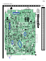
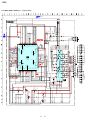
4-2. Printed Wiring Board – MAIN Board – ........................
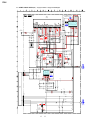
4-3. Schematic Diagram – MAIN Board (1/3) – ..................
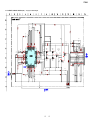
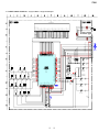
4-4. Schematic Diagram – MAIN Board (2/3) – ..................
4-5. Schematic Diagram – MAIN Board (3/3) – ..................
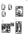
4-6. Printed Wiring Boards – KEY/AUX Boards – ..............
4-7. Schematic Diagram – KEY/AUX Boards – ..................
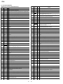
4-8. IC Pin Function Description ...........................................
4.
7
8
9
10
12
13
14
15
16
18
19
20
EXPLODED VIEWS
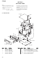
4-1. Main Section ................................................................... 22
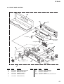
4-2. Front Panel Section ......................................................... 23
5.
2
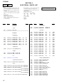
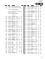
ELECTRICAL PARTS LIST ............................... 24
Notes on chip component replacement
• Never reuse a disconnected chip component.
• Notice that the minus side of a tantalum capacitor may be damaged by heat.
Flexible Circuit Board Repairing
• Keep the temperature of the soldering iron around 270 ˚C during repairing.
• Do not touch the soldering iron on the same conductor of the
circuit board (within 3 times).
• Be careful not to apply force on the conductor when soldering
or unsoldering.