1
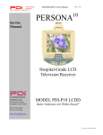
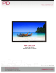
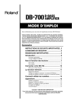
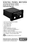
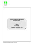
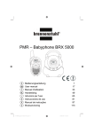
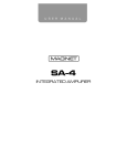
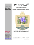
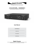
10
Service
Manual
PERSONA
Communication
Systems, Inc.
40 Greenwood Lane
Springboro, Ohio
45066
PH: 937-743-6010
FX: 937-743-5664
http://www.pdiarm.com
Document Number PD196-068 R2
Hospital-Grade LCD Television
For Serial Numbers xxxx-xxxxxx-A
Model P10LCD
Color Television
Better Solutions Are Within Reach®
Page 1 of 24
Graphical Symbols
This lightning flash with arrowhead symbol, within an equilateral is
intended to alert the user of the presence of uninsulated “dangerous
voltage” within the product’s enclosure that may be of sufficient
magnitude to constitute a risk of electric shock to persons.
The exclamation point within an equilateral triangle is intended to alert
the user of the presence of important operating and maintenance
(servicing) instructions in the literature accompanying the appliance.
This service manual contains various CAUTIONS and WARNINGS
indicated by triangular warning symbols, which should be read and
understood in order to minimize the risk of personal injury to service
personnel and customers. The possibility exits that improper service
methods may damage the equipment or result in property damage or
user injury. It also is important to understand that these CAUTIONS and
WARNINGS are not exhaustive. PDI could not possibly know, evaluate
and advise the service industry of all conceivable methods in which
service might be done or of the possible hazardous consequences
of each method. Accordingly, a servicer who uses a service procedure or
tool which is not recommended by PDI must first satisfy themselves
thoroughly that neither their safety nor the safe operation of the
equipment will be compromised by the service method selected.
Product Safety Servicing Precautions
1. MODIFICATIONS Do not attempt to modify this product in any way
without written authorization from PDI. Unauthorized modifications
will not only void the warranty, but may lead to your being liable for
any resulting property damage or user injury.
Voltage
AC
DC
Range
18-32 Volts
18-32 Volts
2. POWER SOURCE Use only a power source from a CSA Certified /
UL Approved Class 2 Power Supply suitable for use in a Health Care
Facility. This TV will operate on either DC or AC voltage.
3. X-RAYS X-Ray Radiation is not a concern since this TV does not
incorporate a CRT.
4. REPLACEMENT PARTS Parts critical to the safe operation of this
television are marked with a
on schematics or drawings.
Replace only with the part number specified.
5. SAFETY CHECKS This hospital grade television requires special
safety checks before returning to service. Observe and follow the
“Safety Check” section in this service manual.
Document Number PD196-068 R2
Page 2 of 24
Table of Contents
Graphical Symbols .......................................................................................................................... 2
Product Safety Servicing Precautions ............................................................................................. 2
Table of Contents ............................................................................................................................ 3
Copyright, Disclaimer, and Trademarks .......................................................................................... 4
Regulatory Information .................................................................................................................... 4
Product Identification ....................................................................................................................... 5
Remote Control................................................................................................................................ 6
General Specification ...................................................................................................................... 7
Disinfecting and Cleaning.............................................................................................................. 12
Hidden Factory Menu .................................................................................................................... 13
Picture and Power Supply Adjustments ........................................................................................ 14
Pan Adjustment ............................................................................................................................. 15
Tilt Adjustment ............................................................................................................................... 16
Main Circuit Board Interconnections.............................................................................................. 17
IR / Speaker Board Interconnections ............................................................................................ 18
Safety Checks................................................................................................................................ 19
Schematic & Troubleshooting........................................................................................................ 22
Document Number PD196-068 R2
Page 3 of 24
Copyright, Disclaimer, and Trademarks
Copyright
PDI Communication Systems, Inc. claims proprietary right to the material disclosed in this service
manual. This manual is issued in confidence for servicing information only and may not be used
to manufacture anything shown herein. Copyright 2004 by PDI Communication Systems, Inc. All
rights reserved.
Disclaimer
The author and publisher have used their best efforts in preparing this manual. PDI
Communication Systems, Inc. makes no representation or warranties with respect to the
accuracy or completeness of the contents of this manual and specifically disclaim any implied
warranties of merchantability or fitness for any particular purpose and shall in no event be liable
for any loss of profit or any other damages, including but not limited to special, incidental,
consequential or other damages. The information contained herein is believed accurate, but is
not warranted, and is subject to change without notice or obligation.
Trademarks
All brand names and product names used in this manual are trademarks, registered trademarks,
or trade names of their respective holders.
PDI and Better Solutions Are Within Reach are registered trademarks of PDI Communication
Systems, Inc., Springboro, Ohio.
Regulatory Information
FCC
This equipment has been tested and found to comply with the limits for a Class B digital device,
pursuant to part 15 of the FCC Rules. These limits are designed to provide reasonable protection
against harmful interference when the equipment is operated in a residential or commercial
installation. If this equipment does cause harmful interference to radio or television reception,
which can be determined by turning the equipment off and on, the user is encouraged to try to
correct the interference by one of more of the following measures:
• Reorient or relocate the receiving antenna.
• Increase the separation between the equipment and receiver.
• Connect the equipment into an outlet on a circuit different from that to which the receiver
is connected.
• Consult the dealer or an experienced radio/TV technician for help.
Underwriters Laboratories
The model PDI-P10LCD Hospital Grade LCD TV is a specialized LCD
television and should be installed to National Electrical Code specifications.
This device is safety tested and listed by the Underwriters Laboratories as a
product suitable for use in health care facilities in both the United States
and Canada.
Document Number PD196-068 R2
Page 4 of 24
Product Identification
PRODUCT LABEL
The P10LCD is easily identified using the product label located in the center of the back cabinet..
TM
Communication
Systems, Inc.
Hospital Grade
LCD TV Receiver
E136994
2L94
PERSONA10 LCD TV
RATED: 28V ~ 60 Hz 15W
PDI Communication Systems, Inc.
40 Greenwood Lane Springboro, Ohio 45066 USA
LISTED
For additional information please refer to the user instructions.
THIS DEVICE COMPLIES WITH PART 15 OF THE FCC RULES. OPERATION IS SUBJECT TO
THE CONDITION THAT THIS DEVICE DOES NOT CAUSE HARMFUL INTERFERENCE.
CAUTION
ATTENTION
RISK OF ELECTRIC SHOCK
DO NOT OPEN
RISQUE DE CHOC ELECTRIETUE
NE PAS QUVRIR
TO REDUCE THE RISK OF ELECTRIC SHOCK, DO NOT
REMOVE COVER (OR BACK). NO USER-SERVICEABLE PARTS
INSIDE. REFER SERVICING TO QUALIFED SERVICE
PERSONNEL.
AFIN DE REDUIRE LES RISQUES DE CHOC ELECTIQUE, NE
PAS RETIRER LE COUVERCLE (OU LE PANNEAU ARRIER).
AUCUN ORGANE INTERNE NE PEUT ETRE REPARE PAR
L’UTILISATEUR. CONFIER L’APPAREIL A UN DEPANNEUR
QUALIFIE.
1234-567890-a
0123-456789-A
MADE IN USA / FABRIQUE EN USA
SERIAL NUMBER
The serial number is located at the lower right corner of the product label.
1234-567890-a
0123-456789-A
Serial Number Format Explanation
a. Digits 01 are year of manufacture. Example year 2003 would be 03.
b. Digits 23 are week of manufacture. Example13 would be week 13.
c.
Digits 456789 is the TV unit serial number. Example 000001 is the first unit
manufactured.
d. Letter A is single letter denoting the TV model revision level. For example, A would be
the initial model. First model revision would be B. The second model revision would be
C and so on.
Document Number PD196-068 R2
Page 5 of 24
Remote Control
The P10LCD requires a remote control (part number PD108-412) to program the set. You will
NOT find a remote control packed with the television. The remote control is shipped separate
from the television. The remote control has a limited range to prevent dual programming of an
adjacent room TV. Stand within 3 feet or closer from the front of the TV to use the remote.
PROGRAMMING REMOTE (PD108-412)
POWER
FEATURE
ENTER
CLOSED CAPTIONS
MUTE
Channel, Volume,
Setup Cursor Controls
CHANNEL NUMBERS
TIERS
Set current service level
(tier) directly without
accessing setup Menu
PAID
Turns TV Rental Lamp On
SETUP
Activates On-Screen
Programming Menus
FEATURE LOCK
Enable or disable “Feature”
button for rental operations
NOTE: All non-labeled
buttons inactive
Document Number PD196-068 R2
Page 6 of 24
General Specification
1. SYSTEM
LCD
Size
Type
Format
Brightness
Viewing Angle
Contrast Ratio
Surface Treatment
Back-Lights
Quantity
Type
Color System
Type
Color Depth
Speaker
Quantity
Location
Size
Impedance
Output
Distortion
Earphone
Location
Size
Monaural
Stereo
Internal Speaker
Computer Monitor Capable
Internal DVD
Keylock
10.4” Diagonal
Amorphous Silicon TFT (Thin Film Transistor)
640 x 480 Pixel (RGB)
330 NITS
55º Vertical, 110º Horizontal
180:1
Antiglare Hard Coating
2
CCFL
NTSC 3.58
262,144
1
Front Mounted
28.5 x 40 mm
8 ohms
1 Watt Max.
10% at 0.8W
Side Mounted
3.5mm
Yes
No
Disabled during Earphone Use
No
No
None, TV Disable Available Via IR Remote
2. TUNING
Type
System
Input Impedance
Channel Range
Stereo Sound
North American NTSC Type M
Frequency Synthesized
75 ohms
VHF: 2 – 13, UHF: 14 – 69, CABLE 2 –125
No
Multi-Voltage
Externally Powered
DC Voltage
AC Voltage
Power Consumption
Standby Power
Protection
Coax Powered
Yes
Yes, External Power Source Required
18-32 Volts DC
18-32 Volts AC
15 Watts
5 Watts
7A, 125V Fuse, Internal
3. POWER
Yes, Power and RF Diplexed
4. REGULATION
Safety
Testing Laboratory
Document Number PD196-068 R2
Underwriters Laboratories
Page 7 of 24
Testing Type
Healthcare Certified
Interference
X-Radiation
Manufacturing Origin
5. ON SCREEN DISPLAY
Menu Type
Menu Entrance
Format
Colors
Menus
Picture
Brightness
Contrast
Color
Tint
Channel Setup
Signal
Autoprogram
Free
Basic
Premium
Clear Service Level
Free
Basic
Premium
Add/Delete Channels
Free
Basic
Premium
Copy Service Levels
Features
Power ON Channel & Spkr
Free
Basic
Premium
Volume Limiter
Caption Text Mode
Language
Service Levels
Paid
Self Rent
Channel Number
Channel Labels
Sleep Timer
Sound Mute
V-Chip Rating
UL and cUL
Yes, UL6500 and cUL6500
FCC, CFR 47 Part 15 Class B, DOC Class B
N/A
United States
Character
IR Remote Control Only
15 Rows by 30 Columns
15 Foreground, 7 Background
Yes
Yes
Yes
Yes
Air, CATV, CATV-IRC, CATV-HRC
Programmable Tier
Programmable Tier
Programmable Tier
Erasable Tier
Erasable Tier
Erasable Tier
Individual Channels
Individual Channels
Individual Channels
Yes, Tier to Tier Copy
Selectable by Tier
Start Channel, Speaker On/OFF
Start Channel, Speaker On/OFF
Start Channel, Speaker On/OFF
Yes
Enabled, Disabled
English, French, Spanish
Disabled, Free, Basic, Premium
Yes, No
Locked, Unlocked
Yes
No
No
Yes
No
5. FEATURES
Sleep Timer
On/Off Timer
Auto Shut OFF
Document Number PD196-068 R2
No
No
Yes - Disable Mode, Empty (Blank) Tier
Page 8 of 24
Auto Degauss
Anti-Theft Alarm
Rental
Service Levels
Rental Lamps
Patient Self Rent
Payment Lamp
Non-Volatile Memory
Last Channel
Last Volume
Power On Channel
Direct Channel Entry
Channel Numbers
Hospital Welcome Channel
Comb Filter
Auto Channel Memory
Closed Captions
Text Mode Disable
Speaker Mute
6. KEYPAD CONTROLS
Switch
Type
Tactile Feedback
Actuation Force
Life
Front
Power
Volume Up
Volume Down
Channel Up
Channel Down
Mute
CC
Feature
Enter
1
2
3
4
5
6
7
8
9
0
Last
+100
Cursor Up
Cursor Down
Cursor Left
Cursor Right
Rear Controls
Document Number PD196-068 R2
N/A
No
Yes
3
3, Red, Green, Amber
Yes – Programmable
Yes
Yes
Yes
Yes
Yes, Selectable per Tier
Yes, Active Tier Channels Only
Yes
Yes, Selectable on per Tier Basis
Yes
Yes
Yes, CC1, CC2, TEXT1, TEXT2
Yes
Yes
Domed Membrane
Yes
12 Ounces
1,000,000 Cycle Minimum
Yes
Yes
Yes
Yes
Yes
Yes
Yes
Yes
Yes
Yes
Yes
Yes
Yes
Yes
Yes
Yes
Yes
Yes
Yes
Yes
Yes
Yes
Yes
Yes
Yes
None
Page 9 of 24
Indicator
Power
Stand-By
Terminals
Video Input
Audio Input
Video Input
Video Output
S-Video Input
S-Video Output
Earphone
External Speaker
Power/RF Input
Yes, Green LED
No
No
No
No
No
No
No
Yes, Side Mounted, 3.5MM
No
F-Type
7. REMOTE
IR Format
IR Range
Power Source
Total Keys
Keys
Power
1
2
3
4
5
6
7
8
9
0
+100
Last
CH Up
CH Down
Vol Up
Vol Down
Setup
Mute
Feature
Enter
CC (Closed Caption)
Paid
Locked
Unlocked
Disabled
Free
Basic
Premium
Blank(s)
Custom
Range Limited to1 Meter
“AAA” x 2
29
Yes
Yes
Yes
Yes
Yes
Yes
Yes
Yes
Yes
Yes
Yes
Yes
Yes
Yes
Yes
Yes
Yes
Yes
Yes
Yes
Yes
Yes
Yes
Yes
Yes
Yes
Yes
Yes
Yes
Yes – Non Functional
8. PHYSICAL
Cabinet
Document Number PD196-068 R2
Page 10 of 24
Size
Finish
Ventilation
LCD Screen Protector
Weight (Approx.)
Ambient Temperature
Operating
Storage
Relative Humidity
12 x 3 x 15.5 (W x D x H) inches
Smooth
Bottom and Sides Only, Top None
Yes, Supplemental Non-Scratch
7 lbs.
+15ºC to +30ºC
-20ºC to +60ºC
5 to 80% Operational
9. SERVICE
50,000 Hours Minimum
Yes
Yes
Meets ISTA Test Procedure 1G
15 ½”
Reliability
MTBF
Service Information & Parts
Service Manual
Parts List
Transportation Standard
12”
Document Number PD196-068 R2
3”
Page 11 of 24
Disinfecting and Cleaning
The P10LCD should be disinfected before performing any service. The following procedure is
only a recommendation. Your hospital or company may have a different procedure to follow.
CAUTION – Before using any cleaning or disinfecting
agent on the P10LCD, perform a spot check by wetting
a small area of the cabinet. Verify the agent does not
discolor or deteriorate the cabinet.
Disinfecting
1. The P10LCD has been designed to withstand up to a 5% chlorine based disinfectant.
Many alcohol and ammonia based disinfectants have also been tested with success.
However, before using any cleaner or disinfectant, spot check a small area on the
cabinet.
2. Apply the cleaner or disinfectant per its recommended instructions. Note – most
disinfectants require a waiting time following application and prior to wipe-down.
Cleaning
Stubborn ink and other scratch type marks may prove difficult to remove. A dilute solution of
Isopropyl alcohol will generally work when all else fails. However, full strength Isopropyl will
remove the cabinet’s paint. Use with caution!
Document Number PD196-068 R2
Page 12 of 24
Hidden Factory Menu
A hidden factory service menu is available to the knowledgeable service man using the following
procedure. To access the menu use the PDI remote control (part number PD108-412).
1. With the TV turned OFF, activate the hidden factory menu by pressing the following
IR remote key sequence:
SETUP + SETUP + 4 + 0
2. The TV will turn ON automatically. The factory screen is displayed..
PDI Communications Systems, Inc
PDI-P10LCD
LCD Healthcare Television
Main Sfw: V 1.00
KBIR Sfw: V 11
CKSUM: 1C0D
CKSUM: 6895
3. The service menu consists of one read-only menu screen which provides firmware
checksum values indicating which revision is currently programmed into each of the
TV’s two microprocessors.
4. Exit the service menu by turning the TV OFF. Or after 30 seconds the TV will
automatically turn itself OFF.
Document Number PD196-068 R2
Page 13 of 24
Picture and Power Supply Adjustments
Picture
The LCD display does not use magnetic deflection (like a CRT tube display) and does not require
any internal adjustments. Dynamic picture adjustments to Brightness, Contrast, Color, and Tint
are available using the IR Remote Control part number PD108-412 using the Setup / Picture
Menu.
Power Supply Alignment
The P10LCD television utilizes a fixed-voltage switch mode power supply. Internal power supply
adjustment is not necessary.
Document Number PD196-068 R2
Page 14 of 24
Pan Adjustment
Tighten or Loosen
Tension Nut to
Adjust PAN Friction
Arm Nose
Document Number PD196-068 R2
Page 15 of 24
Tilt Adjustment
1. Remove Access
Cover.
2. Adjust Tension Nut
to Hold Tilt Position.
3. Replace Cover.
Document Number PD196-068 R2
Page 16 of 24
Main Circuit Board Interconnections
LCD Panel
Data Ribbon
Coax Swivel
Cable Assy
PD106-430
LCD Panel
Backlight
Connector
J5
J18
J7
J12
J11
LCD Panel
Backlight
Connector
Document Number PD196-068 R2
Keyboard
Ribbon
Page 17 of 24
IR / Speaker Board Interconnections
EMI Shield
ESD Ground Ribbon to
Metal Sub-Plate
Speaker Assy
PD106-431
IR Ribbon to
J11 Main PCB
IR / Speaker
Board
Document Number PD196-068 R2
Page 18 of 24
Safety Checks
Before returning the P10LCD to service, the following safety checks should be performed.
1. PARTS PLACEMENT
Confirm that the screws, parts, and wiring which were removed to allow servicing are put
back in the original positions.
2. SWIVEL RESISTANCE TEST
1. Expose the mounting swivel.
2. Measure the DC resistance between
the input coax shield and swivel as
shown. The resistance value should
read greater than 4 Meg. A lesser
reading indicates a possible
insulation breakdown or short
between the internal metal UBracket and chassis ground which
could increase leakage currents
touchable by the patient.
3. It is recommended that the reading
of the swivel resistance be recorded
as part of the service record.
3. AC LEAKAGE CURRENT TEST
Following re-assembly of the P10LCD
always perform an AC Leakage Current
Test. Use either an approved hospital
leakage meter or the R-C network shown.
SWIVEL LEAKAGE
a. Power the TV using an approved
external 28 VAC power supply. DO
NOT USE A LINE ISOLATION
TRANSFORMER DURING THIS
TEST.
b. Connect one side of the R-C network
to a good earth ground such as a
water pipe, conduit, etc. Touch the
other side of the R-C network to the
top of the metal swivel.
c. Measure the AC voltage drop across
the R-C network. The measured
voltage must not exceed 0.10 volts
RMS (100 millivolts RMS). This
corresponds to 100 microamperes of
AC current. Any value exceeding this
limit constitutes a potential shock
hazard and must be correct
immediately.
d. Record the reading as part of the
service record.
Document Number PD196-068 R2
> 4 Meg
.15 MFD
1,000 ohm
< 100 millivolt
Page 19 of 24
EARPHONE JACK LEAKAGE
e. Now, connect one side of the R-C
network to a good earth ground
such as a water pipe, conduit, etc.
Touch the other side of the R-C
network to the metal ring on the
earphone jack.
f. Measure the AC voltage drop
across the R-C network. The
measured voltage must not exceed
0.10 volts RMS (100 millivolts
RMS). This corresponds to 100
microamperes of AC current. Any
value exceeding this limit
constitutes a potential shock
hazard and must be correct
immediately.
g. Record the reading as part of the
service record.
.15 MFD
1,000 ohm
< 100 millivolt
Document Number PD196-068 R2
Page 20 of 24
Exploded Assembly View
Mounting Screws Not Shown for Clarity
Adjustment Cover
PD133-590
Socket Head Cap Screw
PDISHCS 2520 150
Rear Housing
PD133-587
Lid Seal
PD133-589
Top Shroud
PD133-588
Coax Cable Assy
PD106-430
Main Chassis
Printed Circuit Board
PD128-1378
LCD Panel
PD289-101
Anti-Glare Window Assy
PD133-593
Speaker Assy
PD106-431
Keypad
PD134-237
Document Number PD196-068 R2
Front Housing
PD133-586
Page 21 of 24
Schematic & Troubleshooting
The P10LCD is manufactured with the intention for board level replacement only. Component
level trouble shooting is not supported. A detailed schematic is not provided. The only board
level component available for field replacement is the earphone jack.
J5
F1
PD118-069
C86
Earphone
Jack
PD143-172
J11
SYMPTOM
CHECK
TV DEAD
1.
2.
3.
4.
5.
BLACK PICTURE, SOUND OK
1. Check for on-screen menu and adjust for maximum
brightness and contrast.
2. Verify J5 ribbon connector is seated.
3. Verify 12V peak, 62 Khz switching voltage waveform is
present on both terminals of C86.
4. If switching voltage missing, replace main chassis.
5. If switching voltage present, replace LCD Panel.
PICTURE OK, NO SPEAKER
SOUND
1. Verify TV is not muted. Verify cable is seated into J11 on
Main Chassis and into J2 of IR Board.
2. Verify Earphone is not being used.
3. Verify TV speaker has not been disabled for the current Tier
in the “Feature” / “Power-on Channel and Speaker” menu.
4. Replace speaker.
5. Check sound. If sound missing, replace main chassis.
Document Number PD196-068 R2
Verify TV is connected to a coaxial powered cable.
Check F1 (7A, 125V).
Verify J11 ribbon connector is seated.
Verify J5 ribbon connector is seated.
Replace main chassis.
Page 22 of 24
SYMPTOM
CHECK
PICTURE OK, NO EARPHONE
SOUND
1.
2.
3.
4.
NO COLOR
1.
2.
3.
4.
CAN NOT TUNE A DESIRED
CHANNEL
1.
2.
3.
4.
Verify channel is programmed into current tier.
Tune to channel with remote.
Tune to channel with TV keypad.
Verify correct Signal type is set in “Setup” / “Channel Setup”
menu.
5. Replace main chassis.
TV KEYPAD INOPERATIVE
1.
2.
3.
4.
5.
Verify TV is correctly powered.
Check TV operation with remote control.
Verify J11 Ribbon connector is seated.
If inoperative, replace keypad.
If still inoperative, replace main chassis.
KEY ON TV KEYPAD
INOPERATIVE
1.
2.
3.
4.
Verify key is active in current TV tier and mode.
Press key and check for audible “click”.
If Key will not click, replace Keypad.
If Key inoperative, replace Keypad.
SNOWY PICTURE
1. Verify TV RF signal level is +10dbmv ±2dbmv.
2. Tune to another channel.
3. Verify correct Signal type is set in “Setup” / “Channel Setup”
menu.
4. Replace main chassis.
NOISY PICTURE
1. Verify TV RF signal level is +10dbmv ±2dbmv.
2. Tune to another channel.
3. Turn off nearby equipment if possible and isolate noise
source.
4. Move TV and cables to minimize or eliminate noise.
5. Replace main chassis.
Document Number PD196-068 R2
Verify earphone is fully inserted into TV’s earphone jack.
Try a different earphone.
Verify TV is not muted. Adjust for maximum volume.
Replace Earphone Jack .
Tune TV to another channel. Check for color.
Increase color in “Setup” / “Picture” menu.
Verify correct voltage is used to power TV.
Verify correct Signal type is set in “Setup” / “Channel Setup”
menu.
5. Replace main chassis.
Page 23 of 24
Communication Systems, Inc.
40 Greenwood Lane
Springboro, Ohio 45066 USA
Internet: http://www.pdiarm.com
email: [email protected]
PH: 937-743-6010
FX: 937-743-5664
Document Number PD196-068 R2
Page 24 of 24