1
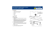
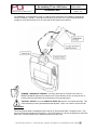
MODEL NUMBER:
Re-Installing TV on a 500 Series
®
Better Solutions Are Within Reach
Suspension Arm
Document Number:
PD196-089R2
Page 1 of 2
The PERSONA 10 is designed to mount on a wall mounted suspension arm capable of supporting a
television weighing 7 pounds. The single coaxial cable on top of the unit is used to supply both low
voltage AC or DC power (range 18 to 32 volts) and the RF signal to the television.
DANGER: ARM RECOIL HAZARD. The safety brake pin must remain in the SAFETY
BRAKE PIN HOLE whenever the television set is removed from the arm or when the arm is
removed from the wall bracket to prevent the arm from springing open.
CAUTION: DO NOT remove the WHITE PLASTIC CAP from the TV’s swivel assembly. This
swivel assembly is factory preassembled and adjusted. There is no need to remove the cap.
IMPORTANT:
These instructions detail re-installing the PDI-P10LCD TV onto the PDI-508C-7 suspension arm. This
arm is configured specifically for this television. The PDI-P10LCD TV may also be installed on other PDI508C arms. Please contact PDi for detailed instructions for this case.
PDi Communication Systems, Inc. 40 Greenwood Lane Springboro, Ohio 45066 USA PH 1-800-628-9870 FX 937-743-5664
MODEL NUMBER:
Re-Installing TV on a 500 Series
®
Better Solutions Are Within Reach
Suspension Arm
Document Number:
PD196-089R2
Page 2 of 2
1. Remove the two nose cover retainer screws. Raise the metal nose cover and slide the television
completely into the arm’s clevis (slot). The swivel retainer plate should rest inside the nose of the arm
and the plastic swivel cap beneath (see picture on previous page).
2. Align the retainer plate’s mounting hole over the arm mounting hole. Thread the 1/4 – 20 x 3/4”
Socket Head Cap Screw through the retainer plate and into the arm’s nose. Tighten.
3. The coax cable in the nose of the arm
should be joined with the coax cable from
the television. Wrench tighten the
connection and cover by sliding the plastic
boot sections into mating position.
IMPORTANT: Finger only tightening of
this cable connection will result in
reliability problems weeks or months later.
Because the TV draws its power current
through this connection, eventually the
finger-tightened connection will loosen,
develop resistance and prompt a service
call. Wrench tighten all “F” fitting
connections!
4. Remove the safety brake pin from the parking brake hole, reattach the acorn nut to the pin, and store
the assembly inside the nose of the arm by attaching it to the coax cable using the attached plastic
clip.
5. Close the metal nose cover onto the nose. Reinstall the two nose cover retainer screws.
6. Optional – Plastic covers may be installed on
some arms. Attach the nose cover section as
follows:
a. Position the Arm Cover halves around the
arm’s nose section. Align exposed pins with
the open holes in the second cover half.
b. Squeeze the two halves together. When the
halves are properly installed there should
only be a thin seam visible where the halves
meet.
7. Cycle the arm once or twice to check for free
movement. Power the TV and verify correct
operation.
END OF INSTRUCTIONS
PDi Communication Systems, Inc. 40 Greenwood Lane Springboro, Ohio 45066 USA PH 1-800-628-9870 FX 937-743-5664