1
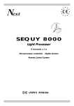
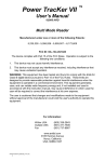
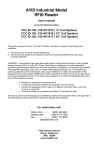
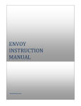
Food Warmer and Holding Station
CFW01-CM-SS
Installation, Operation, and Service Manual
Southern Distributing P.O. Box 893, Brentwood, TN 37024
Table of Contents
Foreword
3
Installation
4
Start UP
4
Operation
4
Clean UP
5
Troubleshooting Suggestions
6
Parts List
7
Drawing 1: Electrical Schematic
8
Drawing 2: Exploded View
9
Illustration 1: Rear View
10
Illustration 2: Unit Leg Set
11
Illustration 3: Product Holding Pan & Crumb Cather Tray
12
Illustration 4: CFWHPP01—Product Holding Pan
13
Illustration 5: Blower Motor & Controls
14
Illustration 6: Controls
15
Illustration 7: CFW-CM-SS—Front View
16
Illustration 8: CFW-CM-SS—Rear View
17
Illustration 9: ON/OFF Switch
18
Illustration 10: Power Cord
19
Illustration 11: Product Pan Partition
20
Illustration 12: Removal of Crumb Pan
21
Illustration 13: Removal of Product Pan
22
Warranty
23
2
Foreword
The Food Warmer and Holding Station is a counter top unit. It requires
proper installation as well as regular cleaning and maintenance to assure
continued operation.
3
Electrical—220 volt 23 amps 1 phase 60 hertz
Installation
Step 1
Lay the warmer on the side so that the leg attachment points on
the bottom of the unit are easily accessible.
Step 2
Attach each of the four legs to the base.
Step 3
Place the unit back to the upright position
Step 4 Provide an electrical service of 220 volt 1 phase. The
breaker should be rated for 30 amps.
Start Up
Step 1 Remove and clean the perforated food tray.
Step 2 Place to power switch located on the upper right side of the hood
into the “ON” position. The pilot light will illuminate and the fans
will operate.
Note: Allow 10 minutes for unit to warm prior to introducing product into
the tray.
Operation
The operating temperature of the warm is factory set. The equipment is
thermostatically controlled and will automatically cycle as required.
4
CLEANING & MAINTENANCE
IMPORTANT: The following cleaning protocol must be followed to ensure safe and satisfactory performance of the countertop food warming station. Failure to follow these procedures
may result in the failure of equipment, ineffective holding of product, reduced product reliability, and may lead to voiding of the equipment warranty.
CAUTION! ALLOW THE COUNTERTOP FOOD WARMING STATION TO SUFFICIENTLY COOL BEFORE ATTEMPTING TO MOVE, PERFORM CLEANING PROCEDURES, OR DISASSEMBLE THE UNIT. FAILURE TO DO SO MAY RESULT IN
PERSONAL INJURY.
DAILY CLEANING:
1. At the end of the work day or upon completion of last holding cycle, remove
product holding pan dividers, product holding pan, and crumb-catching pan.
2. Wash product holding pan dividers, product holding pan, and crumb-catching
pan with warm soapy water, rinse, and allow to sufficiently dry.
3. Using a damp soapy sponge, carefully wash inside & outside surfaces of the unit.
4. Using a damp clean sponge or rag, carefully wipe inside & outside surfaces of
the unit.
5. Allow unit to sufficiently dry.
6. Re-install product holding pan, product holding pan dividers, and crumb
catching pan.
7. All surfaces, crevices, airflow openings, etc. should be checked regularly for any
blockages or residue build-up.
WEEKLY CLEANING:
8. The air intake on the front of the unit should be inspected and cleaned to remove any
obstructions or residue build-up that may have occurred on or around the vent opening.
9. All air flow openings should be checked and cleared of any obstructions.
5
Troubleshooting Suggestions
Unit will not power on 1.Check to make certain there is power to the equipment.
2. Check power switch to determine that it is operational.
Fan operating but no
hot air
1.
2.
3.
4.
Check Thermostat
Check Heater
Check safety thermostat
Check to make sure crumb pan is closed.
Fan not operating
1. Check power switch
2. Check blower motor
3. Check to make sure crumb pan is closed.
6
2.5 Preparation for an Extended Period of Inactivity
Parts List
Part Number
Description
RWEM32
BLOWER
LWSRO1
LIGHTED ROCKER SWITCH
PCBS03
8 POSITION TERMINAL STRIP
HPCCONT01
CONTROL BOARD
HPST0F01
STAND OFF CONTROL BOARD SUPPORT (QTY 4)
HPCHL01
HEATER LIMIT SWICH 300°F
PCCR65
POWER RELAY
PCSW14
TEMP ADJUSTMENT CONTROL
KNOB
PCTT010
3-POLE POWER SPLICING BLOCK
HPCAS01
AIR SENSOR
RCHTR01
HEATER ELEMENT
HLEG95
4” LEGS (QTY. 4)
LEP003
TWISTLOCK 0 A PLUG
HLSW02
LIMIT SWITCH 210°F
HSTAPE01
HEAT SHIELD TAPE
CWFW06
CERAMIC FLAT WASHER
7
Drawing 1: Electrical Schematic
8
Drawing 2: Exploded View
9
Illustration 1: Rear View—(Panel Cover Removed)
Limit Switch
210° F
Heat Shield Tape
HSTAPE02
Ceramic Flat Washer
CWFW06
10
Illustration 2: Unit Leg Set
HLEG95
11
Illustration 3: Product Holding Pan & Crumb Catching Tray
CFWHPPART01
CFWHPP01
CFWCCP01
12
Illustration 4: CFWHPP01 –Product Holding Pan
13
Illustration 5: Blower Motor & Controls
14
Illustration 6: Controls
PCBS03
HPCCONT01
PCSW14
PCCR65
PCTT010
HPCHL01
15
Illustration 7: CFW-CM-SS—Front View
16
Illustration 8—CFW-CM-SS—Rear View
17
Illustration 9—LWSR01—ON/OFF Switch
Rear View
LWSR01
Front View
LWSR01
18
Illustration 10: Power Cord
19
Illustration 11: Product Partition Pan
CFWHPPART01
20
Illustration 12: Removal of Crumb Pan
21
Illustration 13: Removal of Product Pan
22
2.5 Preparation for an Extended Period of InactivWarranty
ity
GUARANTEE: TERMS AND CONDITIONS
Technical Support: The Manufacturer will extend to our clients, as well as those operating our products, a professional service for technical and support assistance. The in-house support team is lead by senior personnel with
both insight and experience in the products and equipment we provide.
The Technical Service Department is maintained by a staff of skilled refrigeration and electrical professionals. It
may be contacted by phone, email, mail, or fax.
Contact information
Phone:
800/423-7761 toll free
985/725-0222
Fax:
985/725-1564
Email: [email protected]
Mailing address: Cospolich Inc., P.O. Box 1206, Destrehan, Louisiana 70047
Delivery Address: Cospolich Inc., 14695 Highway 61, Norco, Louisiana 70079
Installation: The proper installation of equipment is an important factor in the operation and performance of the
equipment. Improper installation may result in loss of warranty coverage.
Intended use: Equipment used for other than its intended purpose will not be covered by this guarantee and may
void the warranty in its entirety.
Replacement parts: We will maintain a suitable inventory of replacement components to support the product in
the field.
Replacement Equipment: For the purpose of field support we will have on hand a small inventory of fully
operational power plant/control systems for the unit packaged and ready to ship. To further support the product
line, we will keep the components on hand to prepare and ship out replacement items within 24 hours of receipt
of warranty claim/processing. If a warranty claim is processed on a Friday or day that falls immediately before a
scheduled holiday, the replacement parts will ship the next scheduled business day.
Shipping Costs: Replacement parts will be shipped by the most efficient and least costly method. In the event
the client requires special shipping it will be provided however the cost associated will not be the responsibility of
the manufacturer.
Understanding: As relates to warranty service: When an authorization number is issued to a third party for
service it is to acknowledge that the manufacturer is aware of the issue and requirement for additional review of
the equipment. We will accept responsibility only after review of the service report. Additionally, we require that
no service to our equipment be authorized or performed without authorization from the appropriate Technical
Service Department representative. To avoid unnecessary and excessive use of third party service companies, the
manufacturer will, in appropriate situations, provide an entire replacement power plant/control assembly to be
swapped out in the field to expedite the repair process. This will consist of all electronic/heating components in
an easy to replace/service assembly. This has been deemed the most expedient and cost effective means of
servicing the equipment in most situations. The manufacturer reserves the right to evaluate all field service requests and to determine the appropriate means by which they are addressed. Every effort will be made to
identify the most efficient and least costly method to service the customer’s needs.
Also, the manufacturer reserves the right to guarantee and/or refuse payment on unauthorized service to our
equipment.
As relates to field assistance: A field representative, responsible for client service, shall agree to assist with cursory
review, troubleshooting, and simple repair/replacement of the field product without cost. This is in order to
expedite repair and reduce expense.
23
Craftsmanship: The manufacturer ensures that the highest level of quality and craftsmanship is provided
during the manufacturing of all products furnished. Any questions regarding either should be brought to the
attention of Technical Support within a week of notice or receipt of order.
Guarantee:
The Manufacturer warrants their cabinets and units to consumers only against defects in material or
workmanship under normal use and service for a period of one year from the date of shipment. The
manufacturer will repair or replace at their option, any part, assembly, or portion thereof, which, by
examination, is deemed to be defective. The manufacturer will pay the labor costs for the repair up to
twelve (12) months from the date of shipment.
Exclusions
The Manufacturer’s obligations under this warranty shall not extend to any malfunction or
other problem caused by unreasonable use, such as, but not limited to, improper setting of
controls, improper installation, improper voltage supply, loose electrical connections or
blown fuses, and damage not attributable to a defect in workmanship. This warranty will not
apply to any cabinet or component part that has been subject to any accident, abuse, misuse,
damage caused by fire or floor or any other act of God, and to any product serviced by an
unauthorized service person or company. It remains the responsibility of the qualified
installation company to provide any accessories required for a specific climate or application.
The Manufacturer does not imply nor warrant the use of this equipment in adverse conditions or beyond its intended use.
Note:
There is no other express warranty on equipment except as stated herein. Any implied warrants of fitness and merchantability
are limited in duration to the duration of this warranty. The liabilities of the manufacturer are limited solely and exclusively to
replacement as stated herein and do not include any liability for any incidental, consequential, or other damages of any kind
whatsoever, whether any claim is based upon theories of contract negligence or tort. Some states do not allow limitations on how
long an implied warranty lasts, or the exclusion of limitations of incidental or consequential damages. So, the above limitations
and exclusions may not apply to you. This warranty gives you specific legal rights and you may also have other rights that vary
from state to state.
The manufacturer reserves the right to modify the terms and conditions of this warranty, with appropriate notice, at any time if
deemed necessary. Appropriate notice shall be defined as no less than 30 business days and shall be done via written and/or
electronic format.
24