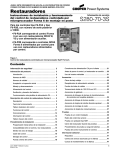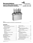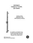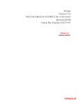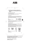
1
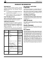
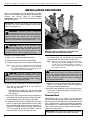
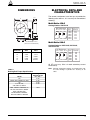
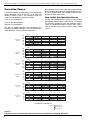
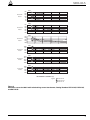
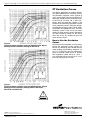
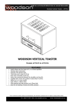
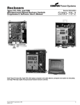
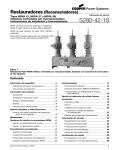
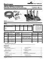
Reclosers
Service Information
“Slip-On” Bushing CT Kits KA712L1S,
KA712L2S, KA712L3S, and KA712L5S
Installation Instructions and Technical Data
Figure 1.
Multi-Ratio, “Slip-On” CT kit.
S280-90-5
Figure 2.
CT properly installed on bushing.
020069KM
020070KM
TABLE 1
Kit Parts
Part Description
Current transformer assembly (CT)
Cover assembly / nameplate
Clamp
Washer
Eyebolt
Palnut
KA712L1S
1
1
3
3
1
1
KA712L2S
1
1
3
3
–
–
KA712L3S
1
1
3
3
1
1
KA712L5S
1
1
1 short, 2 long
3
1
1
Note:
TABLE 2
If desired, connect
set of 3 BCTs for kit
KA712L2S
with
wiring kit KA895RS.
Contact your Cooper
Power Systems representative for additional information.
Kit Description and Application
Catalog
Number
KA712L1S
Kit Description
Multi-ratio (450:5 ratio)
“Slip-on” Bushing CT
Single-Phase
Reclosers
E, 4E, L,
V4L, V4E, VXE
KA712L2S
(see note)
Multi-ratio (600:5 ratio)
“Slip-on” Bushing CT
DV
KA712L3S
Multi-ratio (600:5 ratio)
“Slip-on” Bushing CT
D
R**, RE, RX, RXE, RV, RVE,
W, WE, WV27, WV38X, WVE27,
WVE38X, VW, VWE, VWV27,
VWV38X, VWVE27, VWVE38X
–
KA712L5S
Multi-ratio (600:5 ratio)
“Slip-on” Bushing CT
VXE
–
Three-Phase Reclosers***
3H, 6H, V6H
Sectionalizers
GN3, GV*,
GN3E, GN3VE
Switches
TSC, VRV
GW, GWC
F
–
–
–
–
* Not applicable above Serial No. 1000.
** Not applicable below Serial No. 3733.
*** Installing this kit on all three phases of a three-phase recloser requires three kits (one kit for each phase).
Contents
Safety Information ..................................................... 2
Quality Standards ................................................... 3
Hazard Statement Definitions ................................ 2
Description ............................................................. 3
Safety Instructions .................................................. 2
Installation Procedure .............................................. 4
Product Information .................................................. 3
Connections ........................................................... 4
Introduction ............................................................ 3
Dimensions ................................................................ 5
Acceptance and Initial Inspection .......................... 3
Electrical Data and Characteristics ......................... 5
Handling and Storage ............................................ 3
Correction Curves .................................................. 6
ANSI Standards ..................................................... 3
CT Excitation Curves ............................................. 8
June 2004 • Supersedes 2/03
Printed in USA
1
“Slip-On” Bushing CT Kits KA712L1S, KA712L2S, KA712L3S, and KA712L5S Install. Instr. and Technical Data
!
SAFETY
FOR LIFE
!
SAFETY FOR LIFE
SAFETY
FOR LIFE
Cooper Power Systems products meet or exceed all applicable industry standards relating to product safety. We actively
promote safe practices in the use and maintenance of our products through our service literature, instructional training
programs, and the continuous efforts of all Cooper Power Systems employees involved in product design, manufacture,
marketing, and service.
We strongly urge that you always follow all locally approved safety procedures and safety instructions when working
around high voltage lines and equipment and support our “Safety For Life” mission.
SAFETY INFORMATION
The instructions in this manual are not intended as a substitute for proper training or adequate experience in the
safe operation of the equipment described. Only competent technicians who are familiar with this equipment
should install, operate, and service it.
A competent technician has these qualifications:
• Is thoroughly familiar with these instructions.
• Is trained in industry-accepted high- and low-voltage
safe operating practices and procedures.
• Is trained and authorized to energize, de-energize,
clear, and ground power distribution equipment.
• Is trained in the care and use of protective equipment
such as flash clothing, safety glasses, face shield,
hard hat, rubber gloves, hotstick, etc.
Following is important safety information. For safe installation and operation of this equipment, be sure to read
and understand all cautions and warnings.
Safety Instructions
Following are general caution and warning statements
that apply to this equipment. Additional statements, related to specific tasks and procedures, are located throughout the manual.
DANGER: Hazardous voltage. Contact with
hazardous voltage will cause death or severe
personal injury. Follow all locally approved safety procedures when working around high and low voltage
lines and equipment.
G103.3
!
WARNING: Before installing, operating, maintaining, or testing this equipment, carefully read
and understand the contents of this manual. Improper
operation, handling or maintenance can result in death,
severe personal injury, and equipment damage. G101.0
!
Hazard Statement Definitions
This manual may contain four types of hazard
statements:
DANGER: Indicates an imminently hazardous situation which, if not avoided, will
result in death or serious injury.
!
WARNING: Indicates a potentially hazardous
situation which, if not avoided, could result in
death or serious injury.
!
CAUTION: Indicates a potentially hazardous
situation which, if not avoided, may result in
minor or moderate injury.
!
CAUTION: Indicates a potentially hazardous situation which, if not avoided, may result in equipment damage only.
2
WARNING: This equipment is not intended to
protect human life. Follow all locally approved procedures and safety practices when installing or operating this equipment. Failure to comply can result in
death, severe personal injury, and equipment damage.
!
G102.1
WARNING: Power distribution equipment must
be properly selected for the intended application.
It must be installed and serviced by competent personnel who have been trained and understand proper safety procedures. These instructions are written for such
personnel and are not a substitute for adequate training
and experience in safety procedures. Failure to properly select, install, or maintain power distribution equipment can result in death, severe personal injury, and
equipment damage.
G122.2
!
!
S280-90-5
SAFETY
FOR LIFE
PRODUCT INFORMATION
Introduction
Service Information S280-90-5 provides installation
instructions and technical data for the Kyle® KA712L1S,
KA712L2S, KA712L3S, and KA712L5S “Slip-On”
Bushing CT kits.
Acceptance and Initial
Inspection
Each “Slip-On” Bushing CT kit is in good condition at the
factory and when accepted by the carrier for shipment.
Note:
Users intending to install the “Slip-On” Bushing CT kit
on all three phases of a three-phase recloser must
order three kits (one kit per phase).
Upon receipt, inspect the carton for signs of damage.
Unpack the kit(s) and inspect it thoroughly for damage
incurred during shipment. If damage is discovered, file a
claim with the carrier immediately.
Note:
If desired, connect set of 3 BCTs for kit KA712L2S with
wiring kit KA895RS. Contact your Cooper Power
Systems representative for additional information.
Handling and Storage
Read This Manual First
Read and understand the contents of this manual and
follow all locally approved procedures and safety practices before installing or operating this equipment.
Additional Information
These instructions cannot cover all details or variations in
the equipment, procedures, or process described nor
provide directions for meeting every possible contingency during installation, operation, or maintenance. For
additional information, contact your Cooper Power
Systems representative.
In addition to this manual, also refer to the appropriate
service manual for the model being equipped with the kit.
Product
Type
Model
Service
Information
Single-Phase E, 4E, L
Reclosers
D, DV
VXE
V4L, V4E
S280-10-8
S280-20-1
S280-16-1
S280-10-8
Three-Phase
Reclosers
S280-10-4
S280-10-14
S280-30-2
S280-40-3
S280-30-8
S280-40-7
S280-30-4
S280-30-9
S280-40-5
3H
6H, V6H
R
RE
RX
RXE
RV
RV Serial No. 4111 and after
RVE
W, WV27, WV38X VW,
VWV27, VWV38X
WE, WVE27, WVE38X,
VWE, VWVE27, VWVE38X
Be careful during handling and storage of the kit to minimize the possibility of damage. If the kit is to be stored for
any length of time prior to installation, provide a clean,
dry storage area.
ANSI Standards
Kyle reclosers are designed and tested in accordance
with ANSI standards C37.60 and C37.85 and ANSI
guideline C37.61.
Quality Standards
The Quality System at the Cooper Power Systems, Kyle
Distribution Switchgear plant is certified to the ISO 9001
standard.
Description
The slip-on, multi-ratio bushing current transformers are
especially designed for use with numerous Kyle® singleand three-phase distribution switchgear for load metering
at the equipment location. The CT is available only as a
kit for field installation. The kit consists of the epoxyencapsulated, current-transformer assembly, cover
assembly/nameplate, three clamps and washers for
attaching the CT to the bushing clamping bolts of the
switchgear unit, and an eyebolt lifting lug with a palnut, if
applicable (Figure 1 and Table 1). An eyebolt and palnut
are supplied with kits KA712L1S, KA712L3S, and
KA712L5S for replacement of the standard fabricated lifting
lug, to allow additional clearance for the CT on the head.
Refer to Table 2 for the appropriate application of each kit.
S280-30-1
S280-40-2
Sectionalizers GN3
S270-10-8
GN3E, GN3VE
S270-15-1
GV Serial No. 1302 and above S270-20-2
GV Serial No. 2265 and above S270-20-3
GW
S270-20-3
GWC
S270-21-1
Switches
F
TSC
VRV
S260-50-1
S260-20-10
S260-20-6
3
“Slip-On” Bushing CT Kits KA712L1S, KA712L2S, KA712L3S, and KA712L5S Install. Instr. and Technical Data
INSTALLATION PROCEDURE
Refer to the appropriate service information instruction
manual for the step-by-step procedures to remove the
recloser from service. Refer to the Product
Information section of this manual for specific service
manual information.
IMPORTANT: Remove the recloser from service and
transport it to a clean suitably equipped service center
prior to installing the kit.
WARNING: Hazardous voltage. De-energize
the switchgear before installing this kit. Follow all
locally approved safety practices and procedures when
working around high voltage lines and equipment.
Failure to comply can result in contact with high voltage,
which will cause death or severe personal injury. T232.3
!
CAUTION: Follow all locally approved safety
practices when lifting and mounting the equipment. Use the tapped lifting provisions provided. Lift
the load smoothly and do not allow the load to shift.
Improper lifting can result in equipment damage. G126.0
!
To begin the installation process:
1. Bypass, trip, and de-energize the recloser.
2. Disconnect the lead wires from the bushings.
020071KM
Figure 3.
Mounting clamp is clipped to CT assembly and
attached under bushing clamping bolt.
For kit KA712L5, position the shorter clamp closest to
the eyebolt lifting lug and position the two longer
clamps towards the outside of the head casting.
Note:
3. Carefully transport the unit to a suitable service facility.
Note:
If the recloser is equipped with extra-creepage
bushings, it may be necessary to remove the bushings when installing the "slip-on" bushing CT. This
may require the tank to be dropped.
CAUTION: Equipment damage. Refer to the
specific switchgear unit maintenance manual for
tanking/untanking procedures and related instructions.
Failure to follow these instructions could result in
equipment damage or personal injury.
T238.0
!
4. For kit KA712L2, skip Step 4. Continue with Step 5.
This step is only applicable to kits KA712L1,
KA712L3, and KA712L5:
Remove the fabricated lifting lug from the head
and substitute the eyebolt lug, locking it in position
with the palnut.
5. Slip the CT over the top of the bushing and position it
at the base of the bushing with the terminal box positioned outboard and the black-epoxy-side down.
6. Loosen the three bushing clamping bolts and attach
the CT by slipping the slotted end of the clamp under
the lockwasher while clipping the other end to the CT
(Figure 3). Position the clamp so the top surface of the
CT is at the level of the bushing clamps in order to
maintain the BIL rating of the switch gear unit.
4
Make sure the insulation coating on the CT end of
the clamp is intact and undamaged. If bare metal
on this end of the bracket touches the head, a
"shorted-turn" effect is produced which affects the
CT output and accuracy.
CAUTION: Equipment Damage. Do not attempt
to mount the bushing CT by drilling or tapping into
the CT ring assembly. Perforation of the CT ring can
damage the internal windings and cause ingress of
moisture. Failure to comply can result in equipment
damage and misoperation.
T298.0
!
7. Retighten all three bushing clamping bolts evenly, a
little at a time. Refer to Table 3 for the appropriate
bushing bolt torque specifications.
8. Snap the cover assembly over the terminal connectors of the CT housing. A properly installed CT kit is
shown in Figure 2.
Connections
Connections to the CT are made in the junction box.
Terminal connections for the various ratios are shown on
the inside of the junction-box cover. The junction box has
7/8 in. diameter holes at either end which will accommodate standard 1/2 in. conduit fittings or Pyle-National, DS
series cable-sealing grips (if rubber-covered cable is
used for the meter leads).
IMPORTANT: Do not remove the shorting lead across
CT terminals until external connections are made.
!
S280-90-5
SAFETY
FOR LIFE
DIMENSIONS
ELECTRICAL DATA AND
CHARACTERISTICS
The current transformers have four taps to provide the
following ratios within a ±5% accuracy for conventional
metering.
1.5"
A
Multi-Ratio 450:5
Catalog Number: KA712L1S
B
DC Resistance
Current Connection
Terminals
Ratio
100:5
B-C
40T 18T 29T
150:5
C-D
200:5
A-B
A
C
250:5
B-D
A-C
B
D 300:5
A-D
Winding - NO. 14 AWG 450:5
E
C
.034 Ω .014 Ω .024 Ω
D
4"
7/8" Diameter, 2 holes
(either end of terminal box)
Multi-Ratio 600:5
Catalog Numbers: KA712L2S, KA712L3S,
and KA712L5S
Dimension
A
B
C
D
E
Multi-Ratio
450:5
6 15/16
4 3/4
4 7/8
5 5/8
9 1/8
DC Resistance
Multi-Ratio
600:5
7 3/4
5 1/2
5 9/32
6 1/16
9 15/16
Current Connection
Terminals
Ratio
100:5
C-D
40T 60T 18T
200:5
A-B
300:5
B-C
A
C
400:5
B-D
A-C
B
D 500:5
A-D
Winding - NO. 16 AWG 600:5
.047 Ω .070 Ω .021 Ω
All CTs can carry 150% of rated secondary current
continuously.
Note:
TABLE 3
Bushing Bolt Torque Specifications
Model
3H
GN3E, GN3, GN3VE, 6H, V6H
GV
L, E, 4E, V4L,
V4E, VXE-15, VXE-27
VWE, VWVE27, VWVE38X, R,
RE, RX, RXE, WV27, WV38X
GWC, GW, RV, RVE,
W, WE, WVE27, WVE38X,
VRV, VW, VWV27, VWV38X
Physical construction requires an irregular turns ratio
for some windings to provide ±5% accuracy at all
ratios.
Bushing Bolts
Applied Torque
Ft. • Lbs.
6-10
6-10
6-10
6-10
10-15
5
“Slip-On” Bushing CT Kits KA712L1S, KA712L2S, KA712L3S, and KA712L5S Install. Instr. and Technical Data
Correction Curves
If accuracies greater than the nominal ±5% are desired,
typical correction curves for the CTs at all ratios are
shown in Figures 4 and 5. The correction curves are
drawn for three different transformer burdens:
Curve 1: 0.4 Ω impedance
Curve 2: 0.21 Ω impedance
Curve 3: 0.1 Ω impedance
The 0.21 Ω burden represents the impedance of a
Sangamo Type ADS meter with a 5 A scale and instantaneous elements. The 0.4 Ω burden represents
1.06
Correction
Factor
1.04
1.02
1.00
.98
.96
.94
Correction
Factor
Correction
Factor
Correction
Factor
Correction
Factor
Correction
Factor
1.04
1.03
1.02
1.01
1.00
.99
1.05
1.04
1.03
1.02
1.01
1.00
1.00
.99
.98
.97
.96
.95
1.00
.99
.98
.97
.96
1.00
.99
.98
.97
.96
the impedance of this same meter with a total of 40 feet
of No. 16 AWG conductor leads (meter 20 feet from CT).
The 0.1 Ω burden curves are included to allow for interpolation for other meter loads.
How to Use the Correction Curves
Assume a total burden of 0.4 Ω (Curve 1) with the meter
connected to KA712L1S for a 100:5 A ratio, and reading
3 A. From the appropriate curve the correction factor is
1.024; the corrected secondary current is 3/0 x 1.024 =
3.072 A; and the actual primary current is 3.072 x 100/5
= 61.4 A.
100:5
1
2
3
1
2
3
4
5
1
2
3
4
5
1
2
3
4
5
1
2
3
4
5
1
2
3
4
5
1
2
3
4
5
150:5
1
2
3
200:5
1
2
3
250:5
1
2
3
300:5
1
2
3
450:5
1
2
3
SECONDARY CURRENT (A)
Legend
1 Burden: 0.4 Ω
2 Burden: 0.21 Ω
3 Burden: 0.1 Ω
Figure 4.
Correction curves for 450:5 multi-ratio bushing current transformer, Catalog No. KA712L1S.
6
!
S280-90-5
SAFETY
FOR LIFE
1.06
Correction
Factor
100:5
1
1.04
1.02
2
1.00
.98
3
.96
.94
Correction
Factor
Correction
Factor
1.05
1.04
1.03
1.02
1.01
1.00
1.04
1.03
1.02
1.01
1.00
1.000
.995
Correction .990
Factor
.985
.980
1.020
1.015
Correction 1.010
Factor
1.005
1.000
1.000
.995
Correction .990
Factor
.985
.980
1
2
3
4
5
1
2
3
4
5
1
2
3
4
5
1
2
3
4
5
1
2
3
4
5
1
2
3
4
5
200:5
1
2
3
300:5
1
2
3
400:5
1
2
3
500:5
1
2
3
600:5
1
2
3
SECONDARY CURRENT (A)
Legend
1 Burden: 0.4 Ω
2 Burden: 0.21 Ω
3 Burden: 0.1 Ω
Figure 5.
Correction curves for 600:5 multi-ratio bushing current transformer, Catalog Numbers KA712L2S, KA712L3S,
and KA712L5S.
7
“Slip-On” Bushing CT Kits KA712L1S, KA712L2S, KA712L3S, and KA712L5S Install. Instr. and Technical Data
CT Excitation Curves
For specific applications at burdens different
from those plotted on the correction curves,
the secondary excitation curves (Figures 6
and 7) can be used. These curves plot the CT
secondary voltage versus the exciting current
of the CTs for all ratios. For a given secondary load the secondary voltage is the
product of the secondary impedance and the
actual secondary current. Using this voltage,
the secondary exciting current can be determined from the appropriate curve. The total
secondary current is the sum of the meter
reading and the exciting current. Multiplying
this total secondary current by the actual
turns ratio of the CT winding will give the
actual primary current.
Figure 6.
Typical secondary excitation curves for 450:5 Multi-ratio “Slip-on”
Bushing Current Transformer, Catalog No. KA712L1S.
How to Use the Excitation
Curves
Using the same assumptions as in the example for the correction curves; namely CT
KA712L1S, 100:5 A tap, 0.4 Ω burden and 3 A
meter reading, the secondary voltage is 3 x
0.4 = 1.2 V. From the curve, this voltage produces an exciting current of 0.41 A, and the
total secondary current will be 3 + 0.41 =
3.41 A. Multiply this by the turns, 3.41 x 18 =
61.38 the actual primary current.
Figure 7.
Typical secondary excitation curves for 600:5 Multi-ratio “Slip-on”
Bushing Current Transformer, Catalog Numbers KA712L2S,
KA712L3S, and KA712L5S.
!
SAFETY
FOR LIFE
©2004 Cooper Industries, Inc.
Kyle® is a registered trademark of Cooper Industries, Inc.
KA2048-187 Rev: 03
1045 Hickory Street
Pewaukee, WI 53072 USA
www.cooperpower.com
KDL
6/04