1
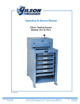
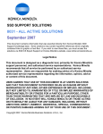
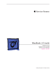
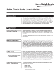
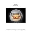
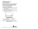
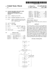
GILSON COMPANY, INC.
Laboratory Equipment for PARTICLE SIZE ANALYSIS • CONSTRUCTION MATERIALS TESTING • SAMPLING
SOIL & ENVIRONMENTAL TESTING
Gilson Porta-Screen
Models PS-3 & PS-4
Operating and Service Manual
Copyright 1999
PHONE: 800-444-1508
740-548-7298
P. O. Box 200, Lewis Center, Ohio 43035-0200
Website: www.globalgilson.com
FAX: 800-255-5314
740-548-5314
MKW 7/99
Gilson Company, Inc.
SAFETY INSTRUCTIONS
GILSON PORTA-SCREEN
PS-3 & PS-4 Porta-Screen
WHETHER YOU ARE THE OWNER, EMPLOYER, OPERATOR, OR MAINTENANCE PERSON FOR
THIS MACHINE, SAFETY IS YOUR RESPONSIBILITY. YOU ARE RESPONSIBLE FOR OPERATING
AND MAINTAINING THIS EQUIPMENT IN COMPLIANCE WITH THESE INSTRUCTIONS AND FOR
USING COMMON SENSE. YOU SHOULD ALWAYS REVIEW AND COMPLETELY UNDERSTAND
THESE SAFETY AND OPERATING INSTRUCTIONS BEFORE USING THIS MACHINE.
∆
!
DANGER: This machine operates on electrical current. Improper use could result in
electric shock, electrocution, injury by explosion, or even death.
I.
Always make sure the motor and electrical components are appropriate and properly
configured for your intended use and available power source. Porta-Screens are normally
wired for 115 volts 60Hz and come with a 1/4 hp non-explosion-proof motor.
II.
Always check electrical wiring for loose connections and for pinched or frayed wiring.
III. Always ground the Porta-Screen. Connect its three-pronged plug to a properly-wired, threepronged, grounded receptacle with appropriate electrical current for the machine.
IV. Always disconnect and lock out the power supply before performing maintenance or repairs
on your machine.
∆
!
∆
!
DANGER: The 1/4 hp, 115-volt motor of the Porta-Screen has internal thermal protection.
Therefore, the motor will automatically shut off if overloaded. The motor will restart
by itself after cooling unless disconnected from its power source during cool-down.
DANGER: Do not use the Porta-Screen in an explosive or hazardous atmosphere.
It is not explosion-proof.
Warning: Operate only in a properly-ventilated area.
Warning: Level the Porta-Screen before operation.
Warning: Stop the Porta-Screen if excessive vibration or machine movement occurs.
Warning: Always take care not to pinch your fingers between the clamp levers and the
machine frame.
Warning: Do not operate without all guards and covers in place.
Warning: Keep all parts of your body away from moving parts of the machine while it
is operating.
Warning: Do not wear loose clothing which might be caught in moving parts of the machine.
Warning: Wear safety glasses, protective clothing, and hearing protection. Wear approved NIOSH/MSHA respirator as required by the sample to prevent your
inhaling any dust which may be considered hazardous.
Gilson Company, Inc.
PS-3 & PS-4 Porta-Screen
Table of Contents
Safety Instructions
Inside Cover
I.
Unpacking & Installation
2
II.
Operation
3
III.
Sample Capacity
4
IV.
Maintenance and Disassembly
V.
Parts
VI.
Faxback Form
5-7
8-11
12
Page 1
Gilson Company, Inc.
PS-3 & PS-4 Porta-Screen
Models PS-3 and PS-4
The Gilson Porta-Screen is a portable shaker for field control of construction aggregates
and for quality control in asphalt and ready-mix plants. It is designed for best separation in the
2" (50.8mm) to No. 16 (1.18mm) range. Model PS-3 holds five screen trays and a pan;
PS-4's capacity is seven trays and a pan.
I. Unpacking & Installation
The Porta-Screen, packed for shipment, weighs
between 225 and 255 lbs, depending on the model
and the number of trays packed inside. Use equipment to adequately to handle this weight safely.
7. Choose your operating site:
A. The Porta-Screen requires a properly-wired,
three-pronged, grounded receptacle with appropriate electrical current for the machine.
1. The Porta-Screen is shipped in a cardboard
carton. Before you accept the shipment, check
the carton for visible damage. Note any damage on the freight bill, and proceed with inspection.
2. Place the carton on its side so that you can
remove the staples from the bottom. Open the
bottom flaps and set the machine upright again.
Lift off the carton and set it aside until you are
sure that the Porta-Screen is in acceptable
condition.
B. Choose a well-ventilated site.
C. Set the Porta-Screen on a solid, stable floor,
platform, or other surface.
8. When you have placed the Porta-Screen in its
operating location, and each time you move it,
level the unit by adjusting the three leveling legs.
To extend a leg, place your foot on the edge of
the pad, and lift up on the machine above
the leg.
3. Check the machine for shipping damage. If you
find concealed damage after you have signed
for the Porta-Screen, call the delivering carrier
immediately for an inspection. Save all packing materials, and leave the Porta-Screen as it
is.
To contract a leg, depress the leg lock tab,
which extends from the case above each
footpad.
Use the bullseye level in the top frame crossbar
as a guide.
4. Check the tag on the electric motor of the PortaScreen to be sure that the machine is wired as
ordered.
After you have placed the Porta-Screen into
service, observe the distribution of sample
material in the trays at the end of a test. If the
material is not evely distributed, re-level the
machine.
5. Release clamping pressure on the Porta-Screen
trays by rotating the clamp levers outward and
upward 180˚.
6. Remove trays by sliding them out the front of
the machine.
9. Reinstall the trays in the Porta-Screen. Leave
them unclamped.
10. Do not plug in the Porta-Screen until you are
ready to use it.
Page 2
Gilson Company, Inc.
PS-3 & PS-4 Porta-Screen
II. Operation
WHETHER YOU ARE THE OWNER, EMPLOYER, OPERATOR, OR MAINTENANCE PERSON FOR THIS
MACHINE, SAFETY IS YOUR RESPONSIBILITY. YOU ARE RESPONSIBLE FOR OPERATING AND
MAINTAINING THIS EQUIPMENT IN COMPLIANCE WITH THESE INSTRUCTIONS AND FOR USING
COMMON SENSE. YOU SHOULD ALWAYS REVIEW AND COMPLETELY UNDERSTAND THESE
SAFETY AND OPERATING INSTRUCTIONS BEFORE USING THIS MACHINE.
Warning:
Operate only in a properly ventilated
area.
Warning:
Level the Porta-Screen before operation.
Warning:
Stop the Porta-Screen if excessive
vibration or machine movement occurs.
Warning:
Always take care not to pinch your
fingers between the clamp levers and
the machine frame.
Warning:
Do not operate without all guards and
covers in place.
Warning:
Keep all parts of your body away
from moving parts of the machine
while it is operating.
Warning:
Do not wear loose clothing which might
be caught in moving parts of the
machine.
Warning:
Wear safety glasses, protective
clothing, and hearing protection. Wear
approved NIOSH/MSHA respirator as
required by the sample to prevent your
inhaling any dust which may be
considered hazardous.
Procedure:
Read and be sure you understand all safety, operating, and timer instructions, as well as specifications
and procedures for your test.
5. Connect the three-pronged plug into a properly-wired, grounded receptacle with appropriate electrical current.
1. Check to see that the Porta-Screen is level.
2. Select and load the appropriate trays.
Fill all the slots: five trays and pan for the PS-3
seven trays and pan for the PS-4
The Porta-Screen will not clamp or operate properly unless fully loaded with trays. If your test
requires fewer trays than the capacity of the
Porta-Screen, you may insert the required trays
in the upper slots with the pan immediately
below. Then fill the lower slots with extra trays.
3. Clamp the trays by rotating the clamp levers so
that they point down.
4. Pour your sample into the top tray. Refer to the
sample capacity information and be sure not to
overload the Porta-Screen.
6. Set and activate the timer.
7. When the machine stops, unclamp the trays by
rotating the clamp levers so they point up.
Remove and empty the trays, following the
directions in your test specifications.
8. When you have finished your test, unplug the
machine. Do not reconnect power until you are
ready to use the machine again.
9. Store clean, empty trays in the unit, leaving
them unclamped.
10. Re-level the machine before the next use.
Page 3
Gilson Company, Inc.
PS-3 & PS-4 Porta-Screen
III. Sample Capacity
Capacity of the Porta-Screen depends on the specifications of the test and the type and size of the
material being tested. For any given sample, the Porta-Screen's maximum capacity is determined by
the tray which has the largest load at the end of the test. This is the limiting tray.
With coarse series trays, (2" to No. 4), the
limiting tray should have no more than one
layer of particles over the wire cloth at the
end of the test. Therefore, lightweight aggregates or coal must be tested in lower sample
weights. High-density ores or pellets may be
tested in larger amounts by weight. Many
light materials are also soft, and test times
should be limited to avoid degradation of the
sample.
Coarse Aggregates:
Minimum quantity of sample is usually established by the specifications of the test
procedure. For example, ASTM C-136 "Specification for the Sieve or Screen Analysis of
Fine and Coarse Aggregates" calls for the
minimum weight of the test sample of coarse
aggregates (density such as limestone or
gravel) as follows:
Nominal Maximum
Size of Particle
mm (in.)
9.5
12.5
19.0
25.0
37.5
50
63
(3/8)
(1/2)
(3/4)
(1)
(1-1/2)
(2)
(2-1/2)
Most samples of up to 2" topsize can be
handled in a single batch without difficulty.
We do not recommend the use of trays with
mesh sizes above 1-1/2", since larger particles become wedged in the mesh and make
it difficult to remove the trays.
Minimum
Sample Weight
Kg. (lb.)
1
2
5
10
15
20
35
(2)
(4)
(11)
(22)
(33)
(44)
(77)
Fine Aggregates:
With fine series trays, (No. 8 to No. 200), the
limiting tray should contain no more than
approximately four grams per square inch of
sieve surface at the end of a test. Assuming
that the material is about the density of sand,
there will be approximately 800 grams maximum on the limiting tray.
These guidelines on minimum sample size
quantities are for representative samples. Always take a much larger amount, perhaps
from several spots in a storage bin or stockpile. Then combine and reduce them to the
correct quantity by splitting.
Page 4
Since the Porta-Screen is designed primarily
for use in the 2" to No. 20 range, separations
in finer sizes will not be as precise. If you are
testing materials exclusively in the fine range,
we recommend equipment specifically designed for this purpose, such as the Gilson
Model SS-8R Sieve Shaker.
Gilson Company, Inc.
PS-3 & PS-4 Porta-Screen
IV. Maintenance
READ AND BE SURE YOU UNDERSTAND ALL SAFETY AND MAINTENANCE INSTRUCTIONS BEFORE
PERFORMING MAINTENANCE ON YOUR PORTA-SCREEN.
ALWAYS DISCONNECT AND LOCK OUT ELECTRIC POWER BEFORE PERFORMING MAINTENANCE.
Clamping System:
1. DISCONNECT AND LOCK OUT ELECTRIC POWER.
per case cover removed, remove lower front
and rear case covers.
2. Load the Porta-Screen with trays and pan, filling all the slots.
b. Apply a small amount of any good-quality bearing grease.
3. Rotate the clamp levers (#38) so that they point down.
c. Reassemble in reverse order.
4. Locate the clamp adjusting nuts (#9), which are on
the lower ends of the four clamp tension rods (#7).
6. Motor Bearings: Lubricate annually.
a. Remove trays, pan, and upper case cover.
5. Tighten the nuts only enough to prevent the trays
from rattling when the machine is operating.
b. Remove lower front and rear case covers.
Lubrication:
c. Find and remove the oil plugs at each end of
the motor.
1. DISCONNECT AND LOCK OUT ELECTRIC POWER.
d. Insert a few drops of oil.
2. Remove and set aside trays and pan.
e. Replace plugs.
3. Remove upper case cover.
f. Reassemble in reverse order.
4. Connection Rod Bearing:
Lubricate the connecting rod bearing (#52)
after every 80 to 100 hours of operation.
a. Rotate drive shaft (#20) slightly by hand until
the grease fitting at the lower end of the
connecting rod (#50) is accessible. (Grease
fitting may be pointing either to the front or to
the back of the Porta-Screen).
b. Apply a small amount of any good-quality bearing grease.
7. Idler Pulley Bearings:
These sealed bearings (#62) do not require
lubrication.
Belts: The Drive Belt (#22) should fit snugly. If the
belt is too tight, it will soon wear out, causing
bearings to wear and resulting in noisy operation. A loose belt may cause the unit to run
too slowly or to slip. Keep the drive pulley
(#21) and motor pulley (#60) aligned so that
the drive belt is straight.
c. Proceed to shaft bearing lubrication.
The Timing Belt (#16) should fit tightly.
5. Shaft Bearings:
There are two bearings (#47), front and rear, on
the drive shaft (#20), and two bearings (#41),
front and rear, on each of the two counterweight
shafts (#12, 13). Some Porta-Screens have
sealed shaft bearings; others have shaft
bearings with grease fittings. If the shaft
bearings on your machine have grease fittings,
lubricate the bearings after every 80 to 100
hours of operation.
a. WITH ELECTRIC POWER DISCONNECTED
AND LOCKED OUT, and trays, pan, and up-
Access to Belts:
1. DISCONNECT AND LOCK OUT ELECTRIC POWER.
2. Remove and set aside trays and pan.
3. Remove all case covers.
4. Drive Belt:
Check tension by pressing on the span of the belt.
If properly adjusted, the belt should be deflected
1/64th of the value of the distance between the
pulleys. To adjust or remove, loosen the motor
mounting bolts (#61); and the motor will slide up,
loosening the belt tension.
Page 5
Gilson Company, Inc.
PS-3 & PS-4 Porta-Screen
a. To adjust, move the motor up or down until the
belt tension is correct. Retighten the nuts.
side of the vibrating unit.
If you notice side-to-side movement of the
vibrating unit during operation, inspect the
guide bearings and replace them if necessary.
We recommend replacement of all three assemblies at the same time.
b. Or remove the loosened belt if it is worn, and install
a new one. Obtain the correct tension by moving
the motor up or down. Retighten the nuts.
c. Continue or reassemble.
a. DISCONNECT AND LOCK OUT ELECTRIC POWER.
5. Timing Belt:
Check tension by pressing on the span of the
belt. The belt should be tight. To adjust or
remove the timing belt, loosen the two idler
bracket mounting screws (#45). Loosen the
nut on the adjusting screw (#46).
b. Remove and set aside trays and pan.
c. Remove top frame screws (#2), and lift off top
frame crossbar (#1).
d. Upper:
(1) Remove mounting screws (#35) to detach
bearing housing (#34).
a. To tighten: Turn in the adjusting screw to pull
the bracket (#17) down and increase tension on the belt. Retighten the nut to hold the bracket
in position. Reassemble.
(2) Replace with new bearing housing assembly.
e. Lower:
(1) Remove all case covers.
b. To replace: Loosen the adjusting screw to permit the idler bracket to move upward, loosening the tension on the
timing belt so that you can remove
it. Before reinstalling belt,
(2) Remove the connecting rod mounting
bolt (#24).
(1) Rotate drive shaft (#20) until the connecting rod (#50) is at its highest position.
(4) Remove mounting screws (#56) to detach
bearing housing unit (#59).
(2) Rotate counterweight shafts (#12,13) until
counterweights are at their lowest position.
(5) Replace with new bearing housing assembly.
(3) Fit the belt around the left counterweight
shaft pulley, around the timing pulley (#49),
above the right counterweight shaft pulley, and around the idler pulley (#19).
(4) Tighten the idler bracket adjusting screw
until the timing belt is tight, making certain
that you do not change the position of the
shafts. Lock the idler bracket in position with the nut. Tighten the bracket
mounting screws.
(3) Lift the entire vibrating unit assembly up
and out of the Porta-Screen frame.
f. Reassemble in reverse order.
DO NOT PLUG IN THE PORTA-SCREEN UNTIL YOU
ARE READY TO USE IT.
2.Connecting Rod & Drive Shaft Bearings:
The connecting rod (#50) can be replaced as an
assembly, or you can press out and replace its
bearing and bushing (#52).
(5) Reassemble.
The drive shaft (#20) has front and rear bearings (#47). We recommend replacement of
both front and rear bearings as a set.
a. DISCONNECT AND LOCK OUT ELECTRIC POWER.
DO NOT PLUG IN THE PORTA-SCREEN UNTIL YOU
ARE READY TO USE IT.
Bearing Replacement:
b. Remove and set aside trays and pan.
c. Remove top frame screws (#2).
d. Lift off top frame crossbar (#1).
1. Guide Bearing Assemblies:
The Porta-Screen has three guide bearing assemblies: each has a housing and guide bushing. The two upper guide bearings (#34) are
mounted to the top frame crossbar. The lower
guide bearing (#59) is mounted to the underPage 6
e. Remove all case covers.
f. Remove the connecting rod mounting bolt (#24).
g. Lift the entire vibrating unit assembly up and
out of the Porta-Screen frame.
Gilson Company, Inc.
PS-3 & PS-4 Porta-Screen
h. Loosen the motor mounting bolts to release tension on the drive belt, and remove
the drive belt from its pulleys.
h. Loosen the idler bracket mounting and adjusting
(#45, 46) to release tension on the timing belt.
i. Loosen the setscrew in the drive pulley (#21),
and slide the pulley off the drive shaft.
j. Loosen the setscrew in the rear drive shaft bearing.
j. Loosen the bolts on the rear counterweight
clamp bracket (#43), and remove the counterweight from the shaft.
k. Loosen the idler bracket mounting and adjusting
screws (#45, 46) to release tension on the timing belt.
k. Loosen the setscrew which holds the rear bearing to the counterweight shaft.
l. Remove the timing belt (#16).
l. Remove the mounting screws (#42) which hold
the front counterweight shaft bearing (#41) to
the main frame.
m. Loosen the setscrew in the drive shaft pulley
(#49), and slide the pulley off the drive shaft.
n. Remove the mounting screws from the front
drive shaft bearing (#47).
o. Hold onto the top of the connecting rod (#50)
while you pull the drive shaft out from the front
of the machine with the front bearing attached.
p. Remove the connecting rod (#50).
i. Remove the timing belt (#16).
m. Pull the counterweight shaft from the front of
the machine with its front counterweight, pulley, and front bearing all attached.
n. Reinstall parts as needed.
o. Reassemble in reverse order. When replacing
timing belt, refer to timing belt instructions and be
sure that the counterweights are aligned properly.
q. Install new connecting rod assembly or press new
bushing and bearing into existing connecting rod. DO NOT PLUG IN THE PORTA-SCREEN UNTIL YOU
ARE READY TO USE IT.
r. Replace drive shaft bearings if needed.
4. Wire Cloth:
s. Continue or reassemble in reverse order. When
Check condition of wire cloth both before and
replacing timing belt, refer to timing belt inafter operation. Test results can be only as
structions and be sure that counterweights are
accurate as the size of wire cloth openings. Alaligned properly.
ways replace with testing grade wire cloth only.
DO NOT PLUG IN THE PORTA-SCREEN UNTIL YOU
Testing grade wire cloth is a precision-made
ARE READY TO USE IT.
material and should be treated with care. The
ASTM E-11 specification permits only very slight
3. Counterweight Shaft Bearings:
variations in average opening and wire diameter.
Each of the two counterweight shafts (#12, 13)
Abrasion due to normal use and/or improper
has a front and a rear bearing (#41). We
cleaning and handling can cause the wire cloth to
recommend replacement of both bearings on
be out of specification to a considerable degree
a shaft. If you have disassembled the Portabefore it appears worn. Check it frequently to be
Screen to replace the connecting rod and/or
sure that it conforms to your test specifications.
drive shaft bearings, skip to step h. Otherwise,
The life of the wire cloth can be prolonged by estabdisassemble as follows:
lishing proper procedures for handling, cleaning, and
a. DISCONNECT AND LOCK OUT ELECTRIC POWER.
storage of trays. The Porta-Pan Accessory is helpful
in the repetitive sequence of emptying trays, cleaning
b. Remove and set aside tray and pan.
wire cloth, and weighing sample fractions.
c. Remove top frame screws (#2).
Wire cloth may eventually sag, reducing its effective
d. Lift off top frame crossbar (#1).
screening area. Wire sizes 2" to No. 14 are rigid and
self-supporting. Trays for No. 16 through No. 80
e. Remove all case covers.
wire cloth contain three wire cloth support strips.
f. Remove the connecting rod mounting bolt (#24).
No. 100 and finer trays have supporting backup
cloth to minimize wear and distortion. When you
g. Lift the entire vibrating unit assembly up and
replace No. 16 and finer wire cloth, always use
out of the Porta-Screen frame.
support strips or backup cloth as indicated.
Page 7
Gilson Company, Inc.
PS-3 & PS-4 Porta-Screen
Parts List for
PS-3 and PS-4 Porta-Screens
Parts
No. Req'd
Outer Case & Frame Parts
1
Top frame cross bar
2
Top frame screw & lock washer
31
Bullseye level with cushion washer
36
Bullseye level adjusting screws
27
Leg lock tab
33
Leg lock tab spring
65,28 Leveling leg (65), with adjusting screw pad, nut & washer
29
Main frame
30
Vibrating unit assembly
Upper case cover
11A Lower case cover, front
Lower case cover, rear
2
1
1
Upper Guide Bearing Assembly Parts
34
Upper guide bearing housing with guide bushing
35
Upper guide bearing mounting screw & lock washer
4
Upper guide bearing pin & set screw
2
4
2
Clamping Assembly Parts, Right & Left
5A
Clamp lever with mounting bracket 6F left side
5B
Clamp lever with mounting bracket 6F right side
38
Clamp lever handle grip
6R
Rear clamp lever mounting bracket
39
Clamp lever mounting bracket screw & lock washer
7
Clamp tension rod
40
Clamp tension rod retainer clip, screw and lock washer
8
Clamp bar
9
Clamp adjusting nut and spacer
1
1
2
2
8
4
4
1
4
Counterweight Assembly Parts
12
Left counterweight shaft (short)
13
Right counterweight shaft (long)
41
Counterweight shaft bearing
42
Counterweight shaft bearing mounting screw & lock washer
14
Counterweight
43
Counterweight clamp bracket
44
Counterweight clamp bracket bolt & lock washer
15
Counterweight shaft pulley & set screw
16
Timing belt
17
Idler bracket
45
Idler bracket mounting screw with lock & flat washers
46
Idler bracket adjusting screw with locking nut
18
Idler pulley mounting screw & lock washer
19/62 Idler pulley with bearing set
1
1
4
8
4
4
8
2
1
1
2
1
1
1
Drive Shaft
20
47
42
49
21
22
Assembly Parts
Drive shaft with eccentric, set screw, and roll pin
Drive shaft bearing
Drive shaft bearing mounting screw & lock washer
Timing pulley & set screw
Drive pulley with set screw
Drive belt
Page 8
1
4
1
3
3
3
3
1
1
2
4
1
1
1
Gilson Company, Inc.
PS-3 & PS-4 Porta-Screen
Parts List for
PS-3 and PS-4 Porta-Screens
Parts
No. Req'd
Connecting Rod Assembly Parts
50
51
52
—
24
54
Connecting rod with grease fitting
Connecting rod rubber bushing
Connecting rod bearing with inner race
(Connecting rod assembly - Parts 50, 51, 52, assembled)
Connecting rod mounting bolt with lock nut
Connecting rod mounting bolt spacer
1
1
1
(1)
1
2
Lower Guide Bearing Assembly Parts
59
56
26
64
Lower
Lower
Lower
Lower
guide
guide
guide
guide
bearing
bearing
bearing
bearing
housing with guide bushing
mounting screw & lock washer
pin
pin clamp bolt with lock nut
1
2
1
1
Electric & Drive Parts
63
60
61
—
—
—
Motor, 1/4 hp, 115V, 60Hz, 1Ph, 1725 RPM
Motor Pulley & set screw
Motor mounting bolt with lock & flat washer
Electric cord assembly, motor-to-timer
Electric cord assembly, with ground plug
Electric cord grip grommet
Timer, Digital (EDA)
Timer, Digital (Artisan)
1
1
4
1
1
1
1
1
Replacement Trays and Wire Cloth
Porta-Screen Tray, complete with wire cloth
Replacement Wire Cloth, complete with
metal shields & resilient gasket backing
Screen Tray Parts
Model
PSA-300
PSA-301
PSA-302
PSA-302
PSA-306
PSA-310
2" to No. 4 inclusive
No. 5 to No. 14 inclusive
No. 16 to No. 80 inclusive w/ wire cloth supports
No. 100, with backup cloth
No. 200, with backup cloth
Dustpan tray
Model
PSA-325
PSA-326A
PSA-326B
PSA-327
PSA-225
2" to No. 4 inclusive
No. 5 to No. 14 inclusive
No. 16 to No. 100 inclusive
No. 200
Backup cloth (use with No. 100 to No. 200)
Model
PSA-336
Page 9
Tray, complete, but without wire cloth,
supports, or backup cloth
Tray side clamp (4 req'd per tray)
Tray bolts & nuts (12 req'd per tray)
Wire cloth support (3 req'd per tray)
PS-3 & PS-4
PARTS DIAGRAM
Gilson Company, Inc.
PS-3 & PS-4 Porta-Screen
Porta-Screen Tray
cloth has metal shields
to eliminate
partial openings.
Porta-Screen has Foot-Tab leveling.
PORTA WHEELS
PS-3 Porta-Screen has predrilled mounting
holes for quick addition of PSA-114 Porta
Wheels for mobility. Set includes two ball
bearing rubber tires attached to steel mounting fixtures.
PSA-114
Page 12