1
command to test one bit of the Instrument Status
byte.)
Bit 6: This bit is set if the RC (recall stored
settings) command finds that the stored values
have been corrupted. A checksum is done on the
settings when they are stored, and if the
computed checksum on recall does not match,
then the command is aborted and this error bit is
set.
IS i
Returns bit i of the Instrument Status Byte.
Example: the command "IS 4" will test bit 4, the
"trigger rate too high" bit. The value "1" will be
returned if a trigger rate error occurred since the last
time the "IS" or "IS 4" command was sent. If no
error had occurred, then the value "0" will be
returned.
Bit 5: This bit is set if an attempt is made to set
a delay to a value below zero or above
999.999,999,999,995 seconds. Because the
delay channels may be linked to each other,
changing a delay to an allowed value may cause
another delay to exceed the allowed range of
values.
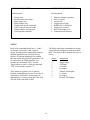
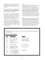
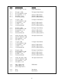
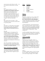
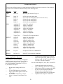
INSTRUMENT STATUS BYTE DEFINITION
Bit Description
7
6
5
4
3
2
1
0
Bit 4: This bit is set if an attempt is made to link
delays in an illogical fashion. For example
A=B+1.000 and B=A+2.000 is a condition
which clearly cannot be satisfied.
Bit 3: This bit is set if the instrument is not in
the correct mode for the command that was sent.
For example, if the instrument set to trigger on
the internal rate generator, the SS (single shot)
command will be ignored and cause bit 3 to be
set.
Memory contents corrupted
Service request
Always zero
Trigger rate too high
80MHz PLL is unlocked
Trigger has occurred
Busy with timing cycle
Command error detected
Bit 7: This bit is set if the instrument settings were
corrupted since the last time power was removed.
The processor computes a checksum of RAM
contents, which contain the instrument settings,
when a power supply dropout is detected. The
checksum is again computed on power-up. If the
checksums do not match, then the default settings
are used (see CL command for default settings) and
the message "Memory Failure" is displayed. A
defective Lithium battery or very noisy ac line
voltages may cause "Memory Failures" to occur.
Bit 2: This bit is set if the value of a parameter
exceeds the allowed range for that parameter.
For example, if the command "TL 20.0" is sent,
the command will be ignored and bit 2 will be
set (because the trigger level may only be set
between ±2.56VDC).
Bit 1: This bit is set if too many or too few
parameters are sent with a command.
Bit 6: This bit is set if the unit is currently
requesting service of the GPIB controller. A service
request may be generated by a variety of conditions
as specified by the service request mask. This bit
allows the controller to see if this instrument was
the one that asserted the service request line on the
GPIB.
Bit 0: This bit is set if the command is
completely unrecognized.
IS
Returns the Instrument Status byte. The
definition of the instrument status byte is given
below. Example: if the trigger rate to the DG535
is too high, bit 4 of the instrument status byte
will be set. Sending the command "IS" will
return the value "16" (if no other bits have been
set). All of the bits in the instrument status byte,
except for the BUSY bit, are latched, ie., if a
trigger rate error is detected at any time, that bit
will stay set until the "IS" command is sent. All
bits, except the BUSY bit, will be reset to 0 after
the "IS" command is executed. (See the IS i
Bit 4: This bit is set if the trigger rate is too fast. The
instrument requires one microsecond after the last
delay has finished to reset all the delay channels. If a
trigger comes during this time, then the front panel
RATE LED will be turned on and bit 4 will be set.
Bit 3: This bit is set if a gross error is detected in the
80MHz PLL. This can happen if the rear panel
switch is set to EXT reference, and the applied
11