1
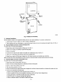
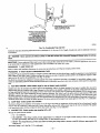
1. Connect 208/230v power leads from field disconnect to yellow and black stripped leads.
2. Connect ground wire to unit ground lug.
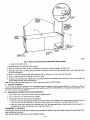
NOTE: Units installed without elecl_Sc beat should have a field-supplied
air leakage and formation of exterior condensation.
sheet metal block-off plate covering the heater opening. This will reduce
Check all factory wiring per trait wiring diagram and inspect factory wiring connections to be sure none were loosened in transit or installation.
WARNING:
Before installing or servicing system, always turn off all power to system. There may be more than 1
disconnect switch. Turn off accessory heater power if applicable. Electrical shock can cause personal injury or death,
CAUTION: If a disconnect switch is to be mounted on the unit, select a location where drill or fastener will not contact
electrical or refrigerant components. Electrical shock can cause personal injury or death.
NOTE: Before proceeding with e|ectrical connections, make certain that supply
Be sure that electrical service provided by the utility is sufficient to handle the
for proper field high- and low-voltage wiring, Make all electrical connections in
apply. Use copper wire only. The unit must have a separate branch electric circuit
and readily accessible from the unit.
B.
24-V Control System Connections
to Unit Printed-Circuit
voltage, frequency, and phase are as specified on unit rating plate.
additional load imposed by this equipmenL See unit wiring label
accordance with NEC and any local codes or ordinances that may
with a field-supplied disconnect switch located within sight from,
Board (PCB)
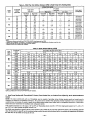
Refer to unit w_ng instructions for recommended wiring procedures. Use No. 18 AWG color-coded, insulated (35°C minimum) wires to make
low-voltage connections between thermostat and unit. If thermostat is located more than 100 ft from unit (as measured along the low-voltage
wires), use No. 16 AWG color-coded, insulated (35°C minimum) wires. PCB is circuited for single-stage heater operation. When additional heater
staging is desired using outdoor thermostats or Intelligent Heat Staging, remove Jumper J2 on PCB to enable staging.
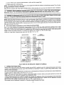
Connect low-voltage leads to thermostat
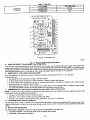
and outdoor unit, (See Fig. 9, Ill, 11, or 12.)
INDOOR CONTROL
FAN COIL
1-SPEED
AIR CONDITIONER
HEAT STAGE 2
N/A
HEAT STAGE
1
....
[_
COOL
I
....
]
....
]
STAGE
FAN
24 VAC HOT
_"
.... @ RE.OVE
Jt JUMPE_
[]
DEHUMIDIFY
FO.
• DEHUMIDIFY
_-'_--_"
24 VAC COMM
HUMIDIFY
_ _ _HUMIDIFIER
/
Ag8477
Fig. 9--FK4C
C.
intelligent
Heat Staging
Fan Coil Wiring with 1-Speed Air Conditioner
Option
Intelligent Heat staging of the electric heat package is possible when the FK4C is installed as a part of a single-speed heat pump system using a
corporate 2-speed programmable thermostat (model TSTATXXP2S01-B),
Thermidistat TM Control, or capable zoning control and any 1 of the
following electxic heat packages:
Relay heaters KFCEH1401N09,
Complete system low-voltage
KFCEHIS01FI5,
KFCEHI701C 15, KFCEHI8lllF20,
KFCEHI901C20,
KFCEH2!01F24,
OR KFCEH2201F30.
wiring as shown in Fig. 9, 10, 11, or 12.
NOTE: Where local codes require thermostat wiring be routed through conduit or raceways, splices can be made inside the fan coil unit. All
wiring must be NEC Class 1 and must be separated from incoming power leads.
A factory-authorized disconnect kit is available for installation of 0- through 10-kw applications. When electric heat packages with circnit breakers
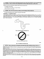
are installed, the circuit breaker can be used as a disconnect. Transformer is factory wired for 230-v operation. For 208-v applications, disconnect
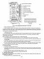
black wire from 230-v terminal on Wansformer and connect it to 208-v terminal. (See Fig. 13.)
The secondary circuit of transformer
is protected by a 5-amp fuse mounted on printed-circuit
board.