1
Installation
Instructions
FK4C
Direct Expansion
Fan Coil
001-006
f
I
J
A98023
NOTE:
Read
This symbol
the entire instruction
--_ indicates
a change
manual
since
before
starting
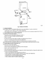
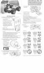
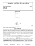
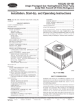
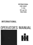
Fig. l_Model
the installation.
the last issue.
SAFETY
Improper
installation,
cause personal
The qualified
adjustment,
injury or property
installer
or agency
alteration,
damage.
FK4C
service,
Consult
maintenance,
a qualified
must use factory-authorized
CONSIDERATIONS
or use can cause explosion,
iastuller,
service
agency,
kits or accessories
when
modifying
packaged
with kits or accessories when installing.
Follow all safety codes. Wear safety glasses and work gloves. Use quenching cloth for brazing
these instructions
thoroughly
and follow all warnings or cautions attached to the unit. Consult
(NEC)
for special
Recognize
safety
fLre, electrical
or your distributor
shock, or other conditions
or branch
this product.
for information
Refer to the individual
operations.
Have rue extinguisher
local building codes and National
winch
may
or assistance.
instnlctions
available.
Electrical
Read
Code
requirements.
information.
This is the safety-alert
symbol/tx.
When
you see this symbol
on the unit and in instructions
manuals,
be alert to
the potential
for personal injury.
Understand
the signal words DANGER,
WARNING,
CAUTION,
and NOTE. These words are used with the safety-alert
symbol. DANGER
identifies the most serious hazards which will result in severe personal injury or death. WARNING
signifies hazards winch could result in personal
injury or death. CAUTION
is used to highl4ght
is used to identify
suggestions
which
unsafe practices
will result
in enhanced
which would
installation,
result in minor
reliability,
personal
injury or product
and property
damage.
NOTE
or operation.
/_, WARNING:
Before installing or servicing unit, always turn off all power to unit. There may be more than 1 disconnect
switch. Turn off accessory heater power if applicable. Electrical shock can cause personal injury or death.
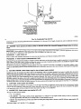
INTRODUCTION
Model FK4C Fan Coil units are designed for flexibility and can be used for upflow, horizontal, or downflow (kit required and manufactured and
mobile homes) applications. These units are designed specifically for Puron (R-410A) and must be used only with Puren air conditioners and heat
pumps as shipped.
Form:
IM-FK4C-08
Cancels:
IM-FK4C-07
Pdnted in U.S.A.
3-02
Catalog No.
63FK-4C4
POWER
ENTRY
"--_
;UPPLIED
SUPPLY
DUCT
OPTIONS
ENTRY
OPTIONS
001-005 21olN.
006 24-1N. FRONT SERVICE ---_
CLEARANCE
I
001
UNIT
003
1
17 In.
A
19 In.
UPFLOW/_
UPELOW/DOWNFLOWJ_------_----_--_J_
FIELD MODIFIED
PNI__
A
2 1/2"
SIDE RETURN
LOCATION FOR
SLOPE COIL
UNITS ONLY
UPFLOWK)OWNFLOW
_.
SECONDARY DRAIN q
UPFLOW/DOWNFLOW
J
PRIMARY DRAIN
FIELD SUPPLIED
RETURN PLENUM
A00088
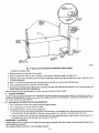
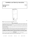
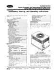
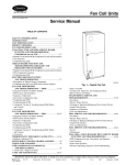
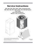
Fig. 2---Slope Coil Unit in Upflow Application
These units are available for application in systems of 24,000 ilvough 60,000 Btah nominal coolingcapacities.Factory-anthorizod,field-instaged
electric heater packages are available in 5 through 30 kw. See Product Data for available accessory kits.
INSTALLATION
PROCEDURE
1---CHECK
EQUIPMENT
Unpack unit and move to final location. Remove carton taking care not to damage unit.
Inspect equipment for damage prior to installation. File claim with shipping company ff shipment is damaged or incomplete. Locate unit rating
plate which contains proper installation information. Cheek rating plate to be sure unit matches job specifications.
PROCEDURE
2--MOUNT
FAN COIL
Unit can stand or lie on floor, or hang from ceiling or wall. Allow spacefor wiring, piping, and servicingunit.
IMPORTANT: When unit is instaned over a finished ceiling and/or living area, building codes may require a field-supplied seconderY condensate
pan to be installed under the entire unit. Some localities may allow the alterative of running a separate, secondary condensate line. Consult local
codes for additional restrictions or precautions.
When installing any fan coil over a finished ceiling and/or living area, installation of a secondary drain pan under entire unit to avoid damage to
ceiling is recommended.
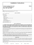
FK4C Fan Coils can be installed for upflow and horizontal-left applications as factory shipped. (See Fig. 2, 4 and 8.) Units can be installed for
horizontal-right applications with field modifications. (See Fig. 5.) Units may be converted for downflow applications using factory-anthorized
accessory kit.
NOTE: To ensure proper drainage for horizontal installations, unit must be installed so it is within 1/8 in. level of the length and width of unit.
A. Upflow Installation
If retttm air is to be ducted, install duct flush with floor. Set unit on floor over opening,
Only use return-air opening provided. All retain air must pass through the coil. (See Fig. 2.)
B.
Modular Units
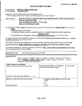
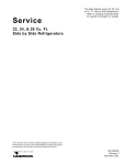
The FK4C Fan Coil in size 006 is a 2-pieee modular unit. Modular construction allows installer to disassemble unit into 2 components, coil box
and blower box, for ease of installation. (See Fig. 3.)
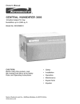
To disassemble unit, remove rear comer brackets by removing 2 screws which secure brackets. (See Fig. 3.) Remove either 2 screws in each front
comer of coil box, or 2 screws in blower box. Do not remove all 4 screws in each corner. (See Fig. 3.) Sections may now be separated by lifting
top section from lower section.
To reassemble, reverse above procedure. Be certain to reinstall all fasteners when reassembling.
--2--
r
- 2SCREWS
2 SCREWS
A95293
Fig. 3_Modular
C.
Unit Assembly
Horizontal Installations
Be sure installation complies with all applicable building codes that may require installation of a secondary condensate
pan.
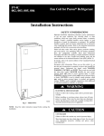
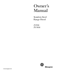
1. Arrange support for unit by setting it in or above secondary condensate pan.
2. When suspending
D.
Horizontal-Right
unit from ceiling dimples in casing indicate proper location of screws for mounting
Conversion
metal support straps. (See Fig. 4.)
of Units with Slope Coils
To convert units for horizontal right installations:
1. Remove blower and coil access panels and fitting panel. (gee Fig. 5.)
2. Remove screw securing coil assembly to right side casing flange.
3. Remove coil assembly.
4. Lay fan coil on its right side and reinstall coil assembly with condensate pan down. (See Fig. 5.)
5. Attach coil to casing flange using previously removed coil mounting screw.
6. Reinstall access panels and fitting panel, aligning holes with tubing connections and condensate pan connections.
Make sure liquid and suction tube grommets
E.
are in place to prevent air leaks and cabinet sweating. Install grommets after brazing.
Horizontal Right Conversion of Units With A-Coil
To convert units for horizontal right installations:
1. Remove blower and coil access panels. (See Fig. 6.)
2. Remove metal clip securing fitting panel to condensate pan. Remove fitting panel.
3. Remove 2 snap-in clips securing A-coil in unit.
4. Slide coil and pan assembly out of unit.
5. Remove horizontal drain pan support bracket from coil support tall on left side of unit and reinstall on coil support rail on right side of unit.
6. Convert air-seal assembly for horizontal right.
a. Remove air-seal assembly from coil by removing 4 screws. (See Fig. 6.)
b. Remove air splitter (B) from coil seal assembly by removing 3 screws. (See Fig. 6-factory-shipped
c. Remove filler plate (A) and install air splitter (B) in place of Idler plate.
d. Install filler plate (A) as shown in horizontal right application.
e. Remove condensate troughs (C) and install on opposite tube sheets.
inset.)
RIMARY
SECONDARY
DRAIN
SUPPLIED
HANGING
STRAPS
001_)05 21-1N.
006 24-1N.
FRONT SERVICE
CLEARANCE
FULL FACE
_F UNIT)
ENTRY
OPTIONS
1 3/4 IN.
FILTER ACCESS
CLEARANCE
SECONDARY
DRAIN
POWER
ENTRY OPTIONS
A001_5
Fig. 4--Slope
Coil in Horizontal-Left
Application
(Factory Ready)
f. Install hose onto plastic spout.
7. Install horizontal pan on fight side of coil assembly.
8. Slide coil assembly into casing. Be sure coil bracket on each comer of vertical pan engages coil support rails.
9. Reinstall 2 snap-in clips to correctly position and secure coil assembly in unit. Be sure clip with large offset is used on fight side of unit
to secure horizontal pan.
10. Remove 2 oval coil access panel plugs and reinstall into holes on left side of coil access panel and fitting panel.
11. Remove insulation knockouts on fight side of coil access panel.
12. Reinstall access and fitting panels, aligning holes with tubing connections and condensate pan connections. Be sure to reinstall metal clip
between firing panel and vertical condensate pan.
Make sure liquid and suction tube grommets are in place to prevent air leaks and cabinet sweating.
F.
Oownflow Installations
To convert units for downflow applications, refer to Installation Instructions supplied with kit for proper installation. For FK4C unit size 003, use
kit Part No. KFADC0201SLP. For FK4C unit sizes 002, 005, and 006 use kit Part No. KFADC0401ACL. Use f'n'eproof resilient gasket, 1/8- to
1/4-in. thick, between duct, unit, and floor.
G.
Manufactured
and Mobile Home Housing Applications
I. Fan coil unit must be secured to the structure using field-supplied hardware.
2. Allow a minimum of 24" clearance from access panels.
3. Recommended method of securing for typical applications
a. If fan coil is away from walL attach pipe strap to top of fan coil using No. 10 self tapping screws. Angle strap down and away from back
of fan coil, remove all slack, and fasten to wall stud of structure using 5/16-in. lag screws. Typical both sides of fan coil.
h. If fan coil is against wall, secure fan coil to wall stud using 1/8-in. thick fight-angle brackets. Attach brackets to fan coil using No. 10
self tapping screws and to wall stud using 5/16-in* lag screws. (See Fig. 7.)
PROCEDURE
3.--AIR DUCTS
Connect supply-air duct over outside of 3/4-in. flange provided on supply-air opening. Secure duct to flange with proper fasteners for type of duct
used, and seal duct4o-unit joint.
Duct connection flanges are provided on unit air discharge connection.
-----4--
COIL MOUNTING
BLOWER
ASSEMBLY
COIL
RAIL
SLOPE COIL.
SKI
PRIMARY DRAIN
DRAINPAN
-OVERFLOW
SECONDARY
HOLE
DRAIN
A02002
Fig. 5--Slope
Coil in Horizontal Right Application
EAL
CONNECTIONS
HORIZONTAL
RIGHT
.,_
APPLICATION
SUPPORT
RAIL
BRACKET
SUPPORT
BRACKET
COIL--_
SUPPORT
RAIL
BRACKET
DRAIN PAN
HORIZONTAL RIGHT
SECONDARY
HORIZONTAL
DRAIN
RIGHT
A00071
Fig. 6--A-Coil
in Horizontal-Right
Application
When using FK4C units with 20-, 24-, and 30-kw electric heaters, maintain a l-in. clearance from combustible materials to discharge plenum and
ductwork for a'distance of 36 in. from unit. Use accessory downflow base to maintain proper clearance on downfiow installations.
Use flexible connectors between ductwork and unit to prevent transmission of vibration. When electric heater is installed, use heat resistant material
for flexible connector between ductwork and unit at discharge connection. Duetwork passing through unconditioned space must be insulated and
covered with vapor barrier.
Ductwork Acoustical Treatment
Metal duct systems that do not have a 90 ° elbow and 10 ft of main duct to first branch takeoff may require internal acoustical insulation lining.
As an alternative, fibrous ductwork may be used if coustmeted and installed in accordance with the latest edition of SMACNA coustmction
standard on fibrous glass ducts. Both acoustical lining and fibrous ductwork shall comply with National Fn_ Protection Association Standards 90A
or B as tested by UL Standard 181 for Class 1 air ducts.
4 _ MAX
_.
'
o_
SECURE
FANFROM
COILTO
STRUCTURE
UiN!T
AWAY
WALL
PIPE STRAP
(TYPICAL BOTH SIDES)
OR
UNIT AGAINST
WALL
1/8-1N. THICK ANGLE
MOUNTING BRACKET
(TYPICAL BOTH SIDES)
DOWN FLOW
BASE KIT (KFACB)
SECURE UNIT TO FLOOR
ANGLE BRACKET OR PIPE STRAP
4" MAX
A02003
Fig. 7--A-Coil
--)
COIL
RACKET
FACTORY SHIPPED
HORIZONTAL LEFT
APPLICATION
COIL
SUPPORT
RAIL
DRAIN PAN
SUPPORT
COIL
BRACKET
HORIZONTAL
DRAIN PAN
PRIMARY DRAIN
HORIZONTAL LEFT
AIR SEAL
SECONDARY DRAIN
HORIZONTAL LEFT
REFRIGERANT
CONNECTIONS
A00072
PROCEDURE
4_ELECTRICAL
Fig. 8---A-Coil in Horizontal Left Application
CONNECTIONS
(Factory Ready)
On units with a factory installed disconnect with pull-out removed, service and maintenance can be safely performed on only the load side of the
conlxol package.
A_ WARNING:
Field wires on the line side of the disconnect found in the fan coil unit remain live, even when the pull-out
is removed. Service and maintenance to incoming wiring can not be performed until the main disconnect switch (remote to
the unit) is turned off. Failure to do so will result in electdcal shock causing personal injury or death.
A.
Line-Voltage
Connections
If unit contains an electric heater, remove and discard power plug from fan coil and connect male plug from heater to female plug from unit wiring
harness. (See Electric Heater Installation lnatmclions.)
For units without eleca'ic beat:
1. Connect 208/230v power leads from field disconnect to yellow and black stripped leads.
2. Connect ground wire to unit ground lug.
NOTE: Units installed without elecl_Sc beat should have a field-supplied
air leakage and formation of exterior condensation.
sheet metal block-off plate covering the heater opening. This will reduce
Check all factory wiring per trait wiring diagram and inspect factory wiring connections to be sure none were loosened in transit or installation.
WARNING:
Before installing or servicing system, always turn off all power to system. There may be more than 1
disconnect switch. Turn off accessory heater power if applicable. Electrical shock can cause personal injury or death,
CAUTION: If a disconnect switch is to be mounted on the unit, select a location where drill or fastener will not contact
electrical or refrigerant components. Electrical shock can cause personal injury or death.
NOTE: Before proceeding with e|ectrical connections, make certain that supply
Be sure that electrical service provided by the utility is sufficient to handle the
for proper field high- and low-voltage wiring, Make all electrical connections in
apply. Use copper wire only. The unit must have a separate branch electric circuit
and readily accessible from the unit.
B.
24-V Control System Connections
to Unit Printed-Circuit
voltage, frequency, and phase are as specified on unit rating plate.
additional load imposed by this equipmenL See unit wiring label
accordance with NEC and any local codes or ordinances that may
with a field-supplied disconnect switch located within sight from,
Board (PCB)
Refer to unit w_ng instructions for recommended wiring procedures. Use No. 18 AWG color-coded, insulated (35°C minimum) wires to make
low-voltage connections between thermostat and unit. If thermostat is located more than 100 ft from unit (as measured along the low-voltage
wires), use No. 16 AWG color-coded, insulated (35°C minimum) wires. PCB is circuited for single-stage heater operation. When additional heater
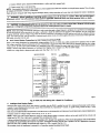
staging is desired using outdoor thermostats or Intelligent Heat Staging, remove Jumper J2 on PCB to enable staging.
Connect low-voltage leads to thermostat
and outdoor unit, (See Fig. 9, Ill, 11, or 12.)
INDOOR CONTROL
FAN COIL
1-SPEED
AIR CONDITIONER
HEAT STAGE 2
N/A
HEAT STAGE
1
....
[_
COOL
I
....
]
....
]
STAGE
FAN
24 VAC HOT
_"
.... @ RE.OVE
Jt JUMPE_
[]
DEHUMIDIFY
FO.
• DEHUMIDIFY
_-'_--_"
24 VAC COMM
HUMIDIFY
_ _ _HUMIDIFIER
/
Ag8477
Fig. 9--FK4C
C.
intelligent
Heat Staging
Fan Coil Wiring with 1-Speed Air Conditioner
Option
Intelligent Heat staging of the electric heat package is possible when the FK4C is installed as a part of a single-speed heat pump system using a
corporate 2-speed programmable thermostat (model TSTATXXP2S01-B),
Thermidistat TM Control, or capable zoning control and any 1 of the
following electxic heat packages:
Relay heaters KFCEH1401N09,
Complete system low-voltage
KFCEHIS01FI5,
KFCEHI701C 15, KFCEHI8lllF20,
KFCEHI901C20,
KFCEH2!01F24,
OR KFCEH2201F30.
wiring as shown in Fig. 9, 10, 11, or 12.
NOTE: Where local codes require thermostat wiring be routed through conduit or raceways, splices can be made inside the fan coil unit. All
wiring must be NEC Class 1 and must be separated from incoming power leads.
A factory-authorized disconnect kit is available for installation of 0- through 10-kw applications. When electric heat packages with circnit breakers
are installed, the circuit breaker can be used as a disconnect. Transformer is factory wired for 230-v operation. For 208-v applications, disconnect
black wire from 230-v terminal on Wansformer and connect it to 208-v terminal. (See Fig. 13.)
The secondary circuit of transformer
is protected by a 5-amp fuse mounted on printed-circuit
board.
FAN COIL
INDOOR CONTROL
HEAT STAGE 2
....
HEAT STAGE I
....
_
2-SPEED
AIR CONDITIONER
[
_
1
REMOVE J2 JUMPER
....
°
COOL STAGE 1
COOL STAGE 2
FAN
24 VAC HOT
! _
• FOR HEAT STAGING
REMOVE
]
J1 JUMPER FOR
DEHUMIDIFY
DEHUMIDIFY
....
!__]. MCOE_
24 VAC COMM
HUMIDIFIER
HUMIDIFY
/
NIA
OUTDOOR
I--{2!:}
_m_J
A98478
Fig. 10_FK4C
Fan Coil Wiring with 2-Speed Air Conditioner
INDOOR CONTROL
1-SPEED
HEAT PUMP
I
....
RVS COOLING
-IEAT STAGE 3
-IEAT STAGE 2
HEAT/C(X)E
STAGE 1 _21-"
FAN[_
24 VAC HOT
FAN COIL
"_
REMOVE J2 JUMPER
"_'- FOR HEAT STAGING
]
I1 JUMPER FOR
' DEHUMIDIFY
....
REMOVE
DEHUMIDIFY
24 VAC COMM
.P_r'_M,D,F,ER
L_,q.
J
HUMIDIFY
RVS HEATING
OUTDOOR
OUTER
I--F_
c&_."#c°,"oN]_l-_t
.............
J
A98475
Fig, 11_K4C
Fan Coil Wiring with 1-Speed Heat Pump
IMPORTANT: Do not use outdoorthermostat with Intelligent Heat Staging.
D.
Comfort Options-Perfect Heat Plus/Super Comfort Heat and Superdehumidify
Warmerheatingand Superdehumidifyoptions arepossible when the FK4CFan Coil is installedwith an outdoortemperaturesensor (needed for
warmer heating only), a ThermidistatTM ConffoL Zone Perfect Plus, or Comfort Zone II. See Procedure 8, I. Comfort Optiousfor complete
description of these features.Complete the system low-voltage wiring as shown in Fig. 9. 10. I 1. or t2.
---8---
INDOOR
FAN COIL
CONTROL
2-SPEED
HEAT PUMP
RVS COOLING
HEAT!COOL
STAGE 1
--:-:I
....
HEAT STAGE 3
i "[_"
.... '"[_]""T'_M_E
J--_2
HEAT/COOL
STAGE 2 __
--:,,
,JUMPER
FOR
HEAT _
FAN
24 VAC HOT
[_--
__.'-I-IN
'REMOVE
- -- -- •_ __
DEHUMIDIFY
24 VAC COMM
[_
J1 FOR
'DEHUMIDIFY
MODES
....
HUMIDIFIER
HUMIDIFY
J
RVS HEATING
ouTDooR
I--F
. -- .__
OUTDOOR
SENSOR
]_'-]
---J
A02005
Fig. 12--FK4C
--)
Fan Coil Wiring with 2-Speed Puron Heat Pump
BLK
A94067
Fig. 13_Transformer
E.
Connections
Ground Connections
AN WARNING:
The cabinet must have an uninterrupted or unbroken ground according to NEC, ANSI/NFPA 70 and local
cedes to minimize personal injury if an electrical fault should occur. The ground may consist of electrical wire or metal
conduit when installed in accordance with existing electrical cedes. (See Ground/Conduit Note below.) Failure to follow this
warning could result in an electrical shock, fire, or death.
NOTE: Use UL listed conduit and conduit connector to connect supply wire(s) to unit and obtain proper grounding. If conduit connection uses
reducing washers, a separate ground wire must be used. Grounding may also be accomplished by using grounding lug provided in control box.
Use of dual or multiple supply circuits will require grounding of each circuit to ground lugs provided on unit and heaters.
PROCEDURE
5---REFRIGERANT
TUBING CONNECTION
AND EVACUATION
Use accessory tubing package or field-supplied tubing of refrigerant grade. Insulate entire suction tube if field-supplied tubing is used. Tubing
package has an insulated suction tube. Do not use damaged, dirty, or contaminated tubing because it may plug refrigerant flow control device.
When tubing package is used and sweat connections are made within 60 sec, coil and tubing system does not zequire evacuation. Always evacuate
coil and field-supplied tubing to 500 microns before opening outdoor unit s_rvic¢ valves.
/_
CAUTION: A brazing shield MUST be used when tubing sets are being brazed to the unit connections to prevent
damage to the unit surface. Braze with Sil-Fos or Phos-copper on copper to copper joints. Wrap s wet cloth around rear of
fitting to prevent damage to TXV.
--9--
/_
CAUTION: To prevent damage to thermostatic expansion valve, remove sensor bulb from vapor tube while brazing
vapor connections. Units have sweat suction and liquid tube connections, Make suction tube connection firsL
Units have sweat suction and liquid tube connections.
Make suction tube connection ftrst.
1. Cut tubing to correct length.
2. Insert tube into sweat connection on unit until it bottoms.
3. Braze with Sil-Fns or Phos-copper.
i
CAUTION:
Wrap a wet cloth around rear of fitting to prevent damage to factory-made
joints.
4, Evacuate coil and tubing system to 500 microns using deep vacuum method.
PROCEDURE
6--CONDENSATE
DRAIN
Units are equipped with primary and secondary 3/4-in. FPT drain connections. For proper condensate line installation see Fig. 2, 4, 5, and 6. To
prevent property damage and achieve optimum drainage performance, BOTH primary and secondary drain lines should be installed and include
properly-sized condensate traps. (See Fig. 14 and 16.) Factory-approved condensate traps are available, Be sure to install plastic push-in plugs in
unused condensate drain fittings. It is recommended that PVC fittings be used on the plastic condensate pan. Do not over-tighten. Finger-tighten
pins 1-112 turns. Use pipe dope.
UNIT
2_MIN
A02(_6
--)
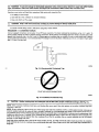
Fig. 14--Recommended
Condensate
Trap
DO NOT USE SHALLOW RUNNING TRAPS!
A95320
Fig. 15--Insufficient
/_,
CAUTION:
Condensate
Trap
Shallow running traps are inadequate and DO NOT allow proper condensate
drainage. (See Fig. 15.)
NOTE: When connecting condensate drain lines avoid blocking filter access panel. Prime both primary and secondary condensate traps after
connecting to drain pan.
NOTE: If unit is located in or above a living space where damage may result from condensate overflow, a field-supplied external condensate pan
should be installed underneath the entire unit, and a secondary condensate line (with appropriate trap) should be run from the unit into the pan.
Any condensate in this external condensate pan should be drained to a noticeable place. As an alternative to using an external condensate pan, some
localities may allow the use of a separate 3/4-in. condensate line (with appropriate a'ap) to a place where the condensate will be noticeable. The
owner of the structure must be informed that when condensate flows from the secondary drain or external condensate pan, the unit requires
servicing, or water damage will occur.
Install traps in the condensate lines as close to the coil as possible. (See Fig. 16,) Make sure that the outlet of each wap is below its connection
to the condensate pan to prevent condensate from overflowing the drain pan. Prime all traps, test for leaks, and insulate traps ff located above a
living area.
--10--
ILTER
ACCESS
PANEL
SECONDARY DRAIN REQUIRED
(USE FACTORY KIT OR
FIELD-SUPPLIED TRAP)
PRIMARY TRAP REQUIRED_X_
(USE FACTORY KIT OR
FIELD-SUPPLIED TRAP OF
SUFFICIENT DEPTH.
STANDARD PRIMARY TRAPS
ARE NOT SUFFICIENT, SEE
RGUP_ OF RECOMMENEDED
CONDENSATE TRAP)
A02(_4
_)
Fig. 16--Condensate
Trap and Unit
Condensate drain lines should be pitched downward at a minimum of 1 in. for every 10 ft. of length. Consult local codes for additional restrictions
or precautions.
_,
CAUTION:
result.
Never operate unit without a filter or with filter access door removed. Damage to blower motor or coil can
IMPORTANT: Factory authorized filters must be used when locating the filter inside the unit. (See Table l.) For those applications where access
to an internal filter is impractical, a field-supplied filter must be installed in the return duct system.
PROCEDURE
T--UNIT
START-UP
Refer to omdcor unit Installation
PROCEDURE
8_EASY
Instructions for system start-up instluctions
SELECT CONFIGURATION
and refrigerant charging method details.
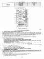
TAPS
Easy Select TM taps are used by the installer to configure a system. ICM2 motor uses the selected taps to modify its operation to a pre-programmed
table of airflows. (See Table 3 and 4.) Airflows are based on system size or mode of operation and those airflows are modified in response to other
inputs such as the need for de-humidification. (See Fig. 17 and 180
The FK4C Fan Coil must be configured to operate properly with system components with which it is installed. To successfully configure a basic
system (see information printed on circuit board label located next to select pins), move the 6 select wires to the pins which match the components
used.
A.
AUX HEAT KW/CFM - Select heater range for size of electric heater installed
Installer must select the auxiliary heat airflow approved for application with kw size heater installed. If no heater is installed, this step can be
skipped. Each select pin is marked with a range of heaters for which airflow, also marked, is approved. For increased comfort select the uarrowest
kw range matching the heater size, for example, 0-10 for 10-kw heater. This airflow must be greater than the minimum CFM for electric heater
application with the size system installed for safe and continuous operation. (See Table 5 and 6 for airflow delivery and minimum CFM.) Note
that airflow marked is the airflow which will be supplied in emergency heat mode and heating mode on air conditioners when electric heat is the
primary heating source. In heat pump heating mode when electric heaters are energized, the ICM2 will run the higher of heat pump heating airflow
and electric heater airflow to ensure safe heater operation. The factory selection is the largest heater range approved. (See Fig. 17, A as indicated.)
B.
AC/HP SIZE - Select system size installed
The factory setting for air conditioner or heat pump size is the largest unit meant for application with the model of fan coil purchased. Installer
needs to select air conditioner or heat pump size to ensure that airflow delivered falls within proper range for the size unit installed. This applies
to all operational modes with the exception of electric heat modes. (See Fig. 17, B as indicated.)
C.
SYSTEM TYPE - Select system type installed AC or HP
type of system must be selected:
1. AC - Air conditioner
/
2. HP-COMFORT - Heat Pump Comfort provides approximately 315 CFM per ton for higher normal heating air delivery temperature.
Provides approximately 350 CFM per ton cooling airflow for good humidity removal.
3. HP-EFF - Heat Pump Efficiency provides same airflow for heating and cooling modes to increase overall lip efficiency; approximately 350
CFIVl per ton.
The factory setting is AC. (See Fig. 17, C as indicated.)
mll--
Table
FILTER KIT
(12 PACK)
1--Filter
Kits
PART NUMBER
SIZE USED Wlilt
KFAFK0212MED
001,002
KFAFK0312LRG
003, 005
OO6
KFAFK041 _
LOWVOLTAGETERMINALBLOCK---_
PRINTEDCIRCUITBOARD---_
^c_=s_
B
......
C
o_
,
o-J Tl
;/
___
lll_l
-i -]-'
_
_
Y,
_
/ ;
@o
o
MOLEX12-PINCONNECTOR
A95275
D.
Fig. 17_etail
of FK4C Printed-Circuit
AC/HP CFM ADJUST - Select Medium, Low, or High airflow
Board
To provide airflow at rates described above,the AC/HP ADJUST selectis factory set to the nominal(nora) tap. The adjustselections H]]LO will
regulate airflow supplied for all operational modes, except non-heat pump healing modes. HI provides 15 percent air/low over nominal unit size
selected and IX) provides 10 percent airflow below nominal unit size selected. Adjust selection options are provided to adjust airflow supplied to
meet individual installalion needs for such things as noise, comfort, and humidity removal. (See Fig. 17, D _ indicated.)
E. ON/OFF DELAY - Select desired time delay profile
Four motor operation delay profiles are provided to customize and enhance system operation. (See Fig. 17, E as indicated)
Selection options are:
1. The standard 90 sec off delay (Factory setting) at 100 percent airflow.
2. No delay option used for servicing unit or when a thermostat is utilized to perform delay functions.
3. A 30 sec on delay with no airflow/90 sec off delay at 100 percent airflow profile is used when it is desirable to allow system ceils time
to heat-up/cool-down in conjunction with the airflow.
4, ENH, enhanced selection, provides a 30 sec on delay with no airflow/plus 150 sec at 70 percent airflow/no off delay for added cemfort.
This profile will minimize cold blow in heat pump operation and could enhance system efficiency,
F. CONTINUOUS FAN - Select desired fan speed when thermostat is set on continuous fan
---> NOTE: If installed with a 2-speed outdoor unit, do not select HI speed continuous fan. If HI is selected, low speed compression will also run HI
speed possibly resulting in insufficient dehumidification.
1, LO speed - factory setting, 50 percent cooling mode airflow.
2. IVIEDspeed - move connector to IVIED, 65 percent cooling mode airflow.
3. HI speed - move connector of HI, 100 percent cooling mode airflow. (See Fig. 17, F as indicated,)
G. Low-Voltage Circuit Fusing and Reference
The low-voltage circuit is fused by a board-mounted 5-amp automotive fuse placed in series with the transformer SEC2 and the R circuit. The C
circuit of the transformer is referenced to chassis ground through a printed circuit run at SECI connected to metal standoff marked with ground
symbol.
H.
Basic Fan Ceil Configuration
The following basic cenfiguratlon of the fan coil will provide ARI rated performance of the heat pump:
1. AUX HEAT KW/CFM - Select the heater range for the size electric heater installed.
2. AC/HP SIZE - Select system size installed.
--12--
ELECTRIC HEAT CONNECTOR
A.95275
Fig. 18--PCB
Wiring Arrangement
3. SYSTEM TYPE - Select system type HP-EFF.
4. AC/HP CFM ADJUST -SeIect NOM.
5. ON/OFF DELAY - Select 0/90 profile.
6. CONTINUOUS
I.
FAN - Select desired fan speed when thermostat is set to continuous fan.
COMFORT OPTIONS-Perfect
Heat Plus/Super
Comfort Heat and Superdehumidify
(See Fig. 20 for Quick Reference
Guide)
Perfect Heal Pins/Super Comfort Heat and Superdehumidify options are possible when the FK4C Fan Coil is installed with an outdoor temperature
sensor, a Thermidistat TM Control, Zone Perfect Plus, or Comfort Zone II.
NOTE: The FK4C Fan Coil provides better than average humidity control and heated air temperature. This configuration will improve the comfort
provided by the heat pump system if more humidity removal or if warmer heating air is desired. While providing this improved comfort, the heat
pump system will operate efficiently, but not at the published HSPF or ARI SEER efficiency.
The following fan coil configuration is recommended for maximum heating and cooling/dehumidifying
comfort: (See Fig. 17.)
1. AUX HEAT KW/CFM - Select narrowcst heater range to match size of electric heater installed (skip this step if no heater is installed).
2. AC/HP SIZE - Select system size installed.
3. SYSTEM TYPE - Select system type HP-COMFORT (for heat pump system) or AC (for air conditioner system).
4. AC/I-IP CFM ADJUST - Select LO.
5, ON/OFF DELAy - Select ENH profile.
6. CONTINUOUS FAN - Select desired fan speed when thermostat is set to continuous fan.
7. If the fan coil is installed with Intelligent Heat Staging capable eleclric heaters, remove jumper J2. (See Fig. 17.)
NOTE: If €onfigm_g
to run warmer heating, do not remove jumper J2 when using 5-, 8-, or 10-kw heaters.
8 Remove jmnper J1 to activate dehumidify modes.
--13---
Table
9. Wire
2--CFM
Range
for FK4C
SYSTEM
FK4CNF001,
018, 024, 030, 036
450-1275
FK4CNF003
024, 030, 036, 042
525-1475
FK4C_
030,036,
042, 048
550-1700
FK4CNB_6
036, 042, 048. 060
550-2150
low voltage
002
connections
as shown
SIZES
Units
FAN COIL SIZE
CFM RANGE
in Fig, 9, 10, 11, or 12.
10. Configure Tbermidistat (or capable zoning system) following its installation instructions for Super Dehumidify
This configuration provides the following comfort enhancements:
operation.
a. A 30 second blower on delay with 150 seconds at 70 percent airflow to allow the indoor coil to warm up or cool down before the blower
is asked to deliver 100 percent airflow reducing the cold blow sensation at start up in beating and allowing die indoor coil to more quickly
reach wet coil operating conditions in cooling.
b. No blower off delay eliminates cold blow which may be associated with running the blower after shut down of the compressor and avoids
re-evaporation of condensed moisture after cooling/dehumidifying
operation.
c. Lower airflow while the compressor is running to reduce draft effects and increase heating air temperature and improved humidity control
during eoohng operation.
d. Intelligent Staging of the electric heater elements to more closely match heating load requirements and provide more consistent heating
air temperatures.
PROCEDURE
9_ACCESSORY
INSTALLATION
A.
Accessory
Electric Heaters
Electric heaters may be installed with the FK4C Fan Coil per instructions
factory-approved electric heater kits.
NOTE: Units installed without electric heat should have a field-supplied
air leakage and formation of exterior condensation.
B.
supplied with electric heater package. See unit rating plate for
sheet metal block-off plate covering the heater opening. This reduces
Auxiliary Terminals
The AUX and HUM terminals on the Easy Select Board are tied directly to the G terminal, and provide a 24-vac signal whenever the G terminal
is energized. (See Fig. 17 and 18.) During Perfect Heat Plus/Super Comfort Heat and Superdehumidify modes, the G signal is not present and the
auxiliary terminals are not energized. If the installation includes the use of one of these operating modes, do not use these terminals to control
accessories. See Electronic Air Cleaner and Humidifier sections for further information.
C.
Electronic Air Cleaner Connections
The AUX1 and AUX2 terminals are not always energized during blower operation, as described above. When using an electronic air cleaner with
the FK4C Fan Coil, use Airflow Sensor Part No. KEAAC0101AAA. The airflow sensor turns on electronic air cleaner when the fan coil blower
is operating.
D. Humidifier/Humidictst
Connections
The HUM1 and HUM2 terminals are not always energized during blower operation, as described under Auxiliary Terminals section. To ensure
humidifier will operate properly, use HUM output of Thermidistat Control, Zone Perfect Plus, or Comfort Zone II to control humidifier operation.
Alternatively, the 24-vac signal can be sourced from the W and C terminal block connections when electric heaters are used as the primary heating
source, or if another humidistat is desired to control the humidifier. (See Fig. 9, 10, 11, and 12.)
E. Dehumidify Capability with Standard Humidictst Connection
Latent capacities for systems using the FK4C Fan Coil are better than average systems. If increased latent capacity is an application requirement,
the field wiring terminal block provides connection terminals for use of a standard humidistat. The FK4C Fan Coil will detect the humidistnt
contacts opening on increasing humidity and reduce its airflow to approximately 80 percent of nominal cooling mode airflow. This reduction will
increase the system latent capacity until the humidity falls to a level which causes the humidistat to close its contacts. When the contacts close,
the airflow will return to 100 percent of die selected cooling airflow. To activate this mode, remove Jumper Jl and wire in a standard humidistaL
F. Dehumidify and Super Dehumidify Capabilities
This model fan coil is capable of responding to a signal from indoor system control (thermostat, Thermidistat, zoning control) to operate in comfort
control modes such as Super Dehumidify Mode. Consult literature provided with indoor system control to determine if these operating modes are
available, and to see control set up instructions, No special setup or wiring of fan coil is required.
PROCEDURE IO--FK4C FAN COIL SEQUENCE OF OPERATION
The FK4C will supply airflow in a range which is more than twice the range of a standard fan coil. It is designed to provide nominal cooling
capacities at a 50°F evaporator temperature and the required airflow which enables it to match with 4 air conditioner or heat pump system sizes.
Table 2 outlines the CFM range for the different FK4C Fan Coil sizes.
A. Continuous Fan
* Thermostat closes circuit R to G.
• The blower runs at cominuonsfan airflow.
B.
Cooling Mode - Single speed or 2-Spead High
• If indoor temperature is above temperature set point and humidity is below humidity set point, thermostat cioses circuits R to G, R to Y/Y2
and R to O.
The fan coil delivers single speed cooling airflow.
--14---
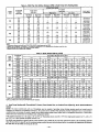
Table 3--FK4C
Fan Coil Airflow Delivery (CFM) in Cooling Mode
OPERATING
UNIT
SIZE
002
0O3
005
006
OUTDOOR
UNIT
CAPACITY
018
024
030
036
024
030
036
042
030
036
042
048
036
042
048
060
MODE
Two-Speed
Application
Single-Speed
Application
Nominal
A/C
Cooling
525
700
875
1050
A/C
Cooling
Dehumidity
420
560
700
840
700
875
1050
1225
560
700
840
980
875
1050
1225
1400
700
840
980
1120
1050
1225
1400
1750
840
980
1120
1400
High Speed
Nomina/
A/C
AJC
Cooling
Cooling
Dehumidity
11O0
880
Low
Nominal
A]C
Cooling
680
FAN ONLY
LO/MED/Hi
Speed
A/C
Cooling
Dehumidity
545
1100
880
680
545
1100
880
680
545
910
745
725
595
995
1240
795
995
1470
1175
11(30
880
t 470
1175
1835
1470
350/350/525
350/455/700
440/570/875
525/680/1050
415/455/700
440/570/875
525/680/1050
610/795/1225
440/570/875
525/680/1050
610/795/1225
700/910/1400
525/745/1050
610/870/1225
700/995/1400
875/1240/1750
NOTE
t, The above airflows result with the AC/HP CFM ADJUST Select jumper set o_ NOM.
2. Airlt(y,v can be adjusted +15 percent or -10 percent by seMctir_ HI or LO respectivM¥ for alt modes except _n _':/¥.
3. Dry coil at 230 volts and with 10kw heater and filter installed.
4. AiHtows shown are at standard air conditions.
•
C.
Thermostat closes circuits R to G, R to YI, R to Y2 and R to O.
The fan coil delivers 2-speed high cooling airflow.
Cooling mode - 2-Speed Low
If indoor temperature is above temperature set point and humidity is below humidity set point, thermostat closes circuits R to G, R to YI and R
to O.
The fan coil delivers 2-speed low cooling airflow.
D.
Cooling Mode - Dehumidification
If indoor temperature is above temperature set point and humidity is above humidity set point, thermostat or Thermidistat
to G, R to O, and R to Y/Y2, and humidistat or Themfidistat opens R to DH.
•
E.
The fan coil delivers airflow which is approximately
Cooling Mode - Superdehumidify
Operation
TM
closes circuits R
80 percent of the nominal cooling airflow to increase the latent capacity of the system.
(See Fig. 20 for Quick Reference Guide)
NOTE: The indoor control used, such as Thermidistat,must be capable of providing Super Dehumidify opemadon
mode and control must be
configured as outlined in its installation insU'ucdons.Consult indoor control literature to determine if control is capable of providing Super
Dehumidify inputs and for configuration instructions.
If the indoor temperature is helow the temperature set point and the humidity is above the humidity set point, the Thermidistat closes circuit R
to O, opens circuits R to DH and R to G, and cycles circuit R to Y/Y2 (for single speed system R to Y1, or R to YI and Y/Y2 for 2-spoed system).
The ICM2 motor reads the G signal to the fan coil while the heat pump is operating, (circuit R to Y/Y2 for single speed system, R to YI or R
to Y 1 and Y/Y2 for 2-speed system), closed (24 vac). If circuit R to G is closed (24 vat), the motor will deliver airflow at the f_ll cooling or cooling
plus dehumidify mode requested value. If circuit R to G is open (0 vac) for super dehumidify mode, the motor delivers reduced airflow to maximize
the humidity removal of the system while minimizing overcooling.
F.
•
•
Electric Heat Heating Mode
Thermostat closes circuit R to W/W1, or W2.
The fan coil delivers the selected electric heat airflow.
G. Heat Pump Heating Mode - Single speed or 2-Speed High
• Thermostat closes circuits R to G and R to Y/Y2.
The fan coil delivers single speed heat pump heating airflow.
• Thermostat closes circuits R to G, R to Y 1 and R to Y/Y2.
The fan co:tl delivers 2-speed high heat pump healing airflow.
H.
•
Heat Pump Heating
Mode - 2-Speed Low
Thermostat closes circuits R to G and R to Y l.
The fan coll delivers 2?speed heat pump heating low airflow.
I. Heat Pump Heating with Auxiliary Electric
Heat
Thermostat closes circuits R to G, R to Y/Y2 and/or R to YI with R to W/WI or W2 (and R to O in the case of defrost).
In the event that electric heating is called for by the thermostat while the heat pump is also operating in either heating or defrost modes, the motor
will modify its airflow output, if necessary, to provide an airflow which is defined as safe for the operation of the electric heater during heat pump
operation. That airflow is the greater of the heat pump heating airflow and the electric heater ohiy ainqow.
--15--
Table 4---FK4C Fan Coil Airflow Delivery (CFM) in Heat Pump Only Heating Mode
OPERATING
UNIT
SIZE
OUTDOOR
UNIT
CAPACITY
MODE
Two-Speed
Application
Single-Speed
Application
High
Heat Pump
Comfort
Heat Pump
Efficiency
002
018
024
030
036
470
630
785
945
525
700
875
1050
OO3
024
030
036
042
630
785
945
1100
700
875
1050
1225
005
O30
036
042
048
785
945
1100
1260
875
1050
1225
1400
OO6
036
042
048
000
945
1100
1260
1575
1050
1225
1400
1750
Speed
Heat Pump
Comfort
Low
Heat Pump
Efficiency
990
Heat Pump
Comfort
1100
FAN ONLY
LO/MED/H][
Speed
Heat Pump
Efficiency
615
350/350/470
350/410/630
440/510/785
525/615/945
680
415/415/630
440/510/785
525/615/945
610/715/1100
990
1100
615
680
990
1100
615
680
1320
1470
820
910
990
1100
670
745
1325
1655
1470
1835
895
1120
995
1240
440/5 i0/785
525/615/945
610/715/1100
700/820/1260
525/670/945
610/780/1100
700/895/1260
875/1120/1575
NOTE
1, The above airflows result with the AC/HP CFM ADJUST select jumper set on NOM.
2. Airflow can be ad usted +15 percent or -10 percent by Selecting HI or LO respectively for all modes except fan only.
3. Dry coil at 230 volts and with lOkw heater and filter ns a led.
4. Airflows shown are at standard air conditions,
Table 5--FK4C
FAN
UNIT
SIZE
OUTDOOR
UNIT
CAPACITY
BTUH
Airflow Delivery (CFM)
ELECTRIC HEATER KW RANGE
0-5
0-10
0-15
0-20
LO
NOM
HI
LO
NOM
HI
LO
NOM
H1
LO
NOM
HI
18,000
625
625
625
675
675
675
*
*
*
*
*
*
001
24,000
650
725
835
*
725
835
875
875
875
*
*
002
30,000
815
905
1040
*
905
1040
900
900
1040
11(30
1100
1100
36,000
980
1085
1250
980
1085
1250
980
1085
1250
1100
1100
1250
24,000
675
725
835
875
875
*
*
*
*
*
*
*
30,000
815
905
1040
875
905
1040
1100
1100
1100
*
*
*
36.000
980
1085
1250
980
1085
1250
1100
1100
1250
1225
1225
1250
42,000
1140
1270
1460
1140
1270
1460
1140
1270
1460
1225
1270
1460
003
FAN
UNIT
SIZE
005
006
O_R
UNIT
CAPACITY
BTUH
ELECTRIC
LO
NOM
HI
LO
NOM
HI
LO
NOM
HI
LO
NOM
HI
30,000
975
975
1040
1100
1100
1100
*
*
*
*
*
*
36,000
980
1085
1250
1100
1100
1250
1250
1250
1250
*
*
*
42,000
1140
1270
1460
1140
1270
1460
1250
1270
1460
1500
1500
1500
48,000
1305;
1450
1665
1305
1450
1665
1305
1450
1665
1500
1500
1665
36,000
ll00
1100
1250
1350
1350
1350
*
*
*
*
*
*
42,000
1140
1270
1460
1350
1350
1460
1525
1525
1525
*
*
*
48,000
1305
1450
1665
1350
1450
1665
1525
1525
1665
1750
1750
1750
60,000
1630
1810
2085
1630
1810
2085
1630
1810
2085
1750
1810
2085
0-10
• Airflow not recommended for heater/syst_temsize.
NOTE: LO, NOM, and HI refer to AC/HP CFM ADJUST
d. Heat Pump Heating with Thermidistat
Guide)
HEATER KW RANGE
0-15
0-20
0-30
selec_on.
TM
Control, Zone Perfect Plus, or Comfort Zone II (See Fig. 20 for Quick Reference
NOTE: The indoor control used, such as a Thermidistat, must be capable of providing wanner heating operation mode and control must be
configured as outlined in its installation instructions. The system must be installed with appropriate outdoor temperature sensor. Consult indoor
control literature to determine if control is capable of providing warmer beating control outputs and for configuration instructions. Consult indoor
control and sensor insmmtions for installation and configuration details.
If the outdoor temperature is in the range of 10° to ,tO*F, the Thermidistat closes circuit R to Y/Y2 (for single speed system R to YI, or R to Y1
and Y/Y2 for 2-speed system) and opens circuit R to G.
The ICM2 motor reads the G signal to the fan coil. If circuit R to G is closed (24 vac), the motor will deliver airflow at the full heating requested
value. If circuit R to G is open (0 vac) for maximum beating comfort, the motor delivers reduced airflow to maximize the temperature and minimize
the draft effect of the heated air leaving the fan coil.
--16--
Table 6---FK4C Minimum CFM for Electric Heater Application
CFM
HEAT PUMP
FAN
COIL
UNIT
H_ATER
UNIT
SIZE
5
8, 9, 10
Heater Only
018
625
625
625
625
024
650
725
030
8O0
875
036
970
970
Heater Only
024
675
700
675
875
030
80O
875
036
975
975
042
1125
1125
Heater Only
030
675
700
800
875
OOl
OO2
SIZE
15
725
KW
18. 20
875
036
975
975
042
1125
1125
048
1305
1305
Heater Only
036
1050
1050
875
875
970
1050
1050
Iloo
1100
1125
1050
1100
I100
1125
1305
1050
1100
1100
1350
1350
042
1125
1125
1350
048
1300
1300
1350
060
1625
1625
1625
1350
1465
1750
OO3
OO5
OO6
24, 30
1040
1040
1050
1225
1225
1050
1400
1225
1225
1305
1050
1400
1750
1750
1750
NOTES:
1. Healer Orfly-Air ccnd_ioner with etecttfc healer application.
2. These airflows are minimum acceptable airflows as UL listed. Actual airflow delivered will be per airflow de_ive_ chad for Electdc Heating Modes.
PROCEDURE
11--TROUBLESHOOTING
ICM MOTOR AND CONTROLS
z_x CAUTION: High voltage is always present at motor. Disconnect power to unit before removing
connectors or servicing motor. Wait at least 5 min after disconnecting power before opening motor.
or replacing
The ICM motor used with this product contains two par_: the control module and motor winding section. Do not assume the motor or module
is defective if it will not start. Go through the steps described below before replacing control module, Easy Select Board or entire motor. The
control module is available as a replacement part.
A.
If motor
turns slowly:
1. Replace panel. Motor may appear to run slowly if access panel is removed.
2. It is normal operation to run noticeably slower if G terminal is not energized in cooling or heat-pump modes.
B.
If motor does not run:
Turn off power and check the following:
1. Check 5 amp fuse on Easy Select Board.
2. Check for 24vac on SEC1 and SEC2. If no voltage is present, check transformer.
3. Check all plugs and receptacles for any deformation which could cause loose connections. Be sure plugs are fully seated.
4. Verify that approximately
230vac is present at motor.
5. Verify low-voltage control signals to motor. The motor receives its control signals through the 12-pin plug (PL-1) on Easy Select Board
and 16-pin plug on wiring harness. (See Troubleshooting Example.) The combinations of pins energized will determine motor speed. (See
Fig, 19,) See Table 7 for circuit board, low-voltage screw terminals energized _md for voltage present at each pin on 12-pin plug (PL-1).
See Table 7 for pin number on 16-pin plug which should have voltage when Easy Select Board screw terminals have 24vat.
C.
Use following procedure
to check
control signals:
THERMOSTAT
1. Remove all thermostat wires from Easy Select Board.
2. Jumper screw terminals (1 at a time): R-G, R-Y/Y2, R-YI, R-WI. If motor runs in all cases, thermostat is miswired, configured incorrectly
or defective. If motor runs in some cases, but not others, condnue to check wiring harness and circuit board.
WIRING HARNESS
I. Shut off power to unit; wait 5 mitt.
2. Remove 5-pin plug from motor.
3. Remove 16-pin from motor.
--17--
J1 JUMPER - PULL FOR
HEAT STAGING
AC_p
CFM ADJUST
i
ONIOFF DELAY
PIN 12
--
DEHUMIDIFICATION
INPUT
--
24 VAC HOT
--
AUXILARY HEAT STAGE 1
--
AUXILIARY HEAT STAGE 2
--
LOW SPEED COMPRESSOR
-SINGLE OR HI SPEED COMPRESSOR
LOW VOLTAGE SCREW TERMINALS
-- FAN
--
REVERSING VALVE
--
COMMON
HEATEFUMOTOR
L
12-PIN CONNECTOR
(PL-1)
d
16-PIN PLUG
PIN 1
A00114
Fig. 19_Control
Signals (Easy Select Board & 16-Pin Plug)
4. Replace 5-pin plug and turn power on.
5. Check for appropriate voltages on 16-pin connector with screw terminals jumpored. (See Table 7 for values and see examples below.)
If signals check correctly and motor does not run, inspect wiring harness for loose pins or damaged plastic that could cause poor connections. If
connections are good, either control module or motor is defective. If proper signals are not presenL check circuit board using procedure below:
12-PIN PLUG (PL-1) ON EASY SELECT BOARD
1. Unplug harness from board.
2. Check for appropriate voltages on pins with Easy Select Board screw terminals juml_red, (See Table 7 for values and see example below.)
If proper signals are not present, replace Easy Select Board, If present at beard and not at 16-pin connector, wiring harness is defective.
TROUBLESHOOTING
EXAMPLE:
Motor is not running on a call for heat-pump heating. System is a single-speed beat pump.
1. After performing
checks in Thermostat section, follow steps 1 thru 5 in Wiring Harness section. Then proceed with example.
2. With all thermostat wires removed from Easy Select Board, place a jumper wire between R and Y/Y2 low-voltage screw terminals on the
Easy Select board.
3. Check Table 7 for pin number on 16-pin connector associated with the Y/Y2 signal. The correct pin is #14. The far right column shows
that (-) 12vdc should be present between pin #14 and pin #1 (common) on the 16-pin connector.
4. Set meter to read DC voltage. Place meter between pins #1 and #14 and check for (-) 12vdc (common side of meter on pin #1). If signal
is presenL the problem is in the module or motor. If signal is noL problem is either in wiring harness or Easy Select Board.
These steps can be repeated for other modes of operation.
To check Easy Select Board:
1. Leave jumper wire in place between R and Y/Y2.
2. Check Table 7 under "Wiring Harness Connection to Easy Select Board" column and row for pin #14 to see pin# on Easy Select Board
that should have voltage. The correct pin is #2. The column on far right will show voltage that should be present between pin #2 and #9
(or #10 common).
3. Place meter between pins #2 and #9 on Easy Select Board and check for (-) 12vde.
4. If voltage is presenL the wiring harness is bad; if noL the Easy Select Board is bad,
O.
Vedfy Motor Winding Section:
Before proceeding with module replacemenL check the following to ensure motor winding section is functional. With control module removed
and unplugged from winding section:
1. The resistance between any 2 motor leads should be similar.
--18--
Table 7_Wiring
Connections
of FK Fan Coil Wiring Harness
16-1N PLUG ON WIRING HARNESS TO MOTOR
Pin # on 16-Pin Plug
WIRING HARNESS CONNECTION TO EASY SELECT BOARD
Si_aal on pin with
Pin 3 on 12-Pin Plug
Wire Color
Screw Tcrrainal
or get-up Selection
Jumpe_ed to R*
Description
I
Common
2
Wl
3
Pin 9 on PL-I
Brown
Pin 7 on PL-I
Violet
Common
Pin 10 on PL-I
Orange
4
5
On/Off Delay Selection
AC/HP Size Selection
On/OFF Delay Selection
White
6
YI
7
AC/HP CFM Adjust
Selection
Auxiliary
Low
Heat Stage
Speed
l
AC or liP
AC/HP Size Selection
Blue
Pin 3 on PL-I
Black
AC/HP CFM Adjust
Selection
Black
24VAC**
(-) 12VI)C**
8
No€ Used
N/A
Not: Used
9
System Type Selection
System Type Selection
Orange
10
Dehumidify
Aux Heat Size
Selection
Pin 12 on PL-I
Aux Heat Size
Selection
12
24v AC
Pin 8 on PL-I
Red
13
W2
Pin 4 on PL-1
White
24VAC**
Y/Y2
Single Speexl AC or
HP, High Speed
2-Speed
AC or HP
Pin 2 on PL-I
Yellow
(-) 12VDC**
15
G
Fan
Pin l on PL-1
Green
24VAC**
16
Not Used
N/A
Not Used
11
14
Auxiliary
Heat Stage
2
Gray
0V (24VAC
on no call)
Violet
24VAC
continuous
* Check voltageswith 16-Pin P_ugdi_onnected frommotor.
** _ese signals will start motor,
2. The resistance between any motor lead and the unpainted motor end plate should be greater than 100K ohms.
If motor winding section fails one of these tests, it is defective arid must be replaced.
START-UP PROCEDURES
Refer to outdoor unit Installation Instructions for system start-up instructions and refrigerant charging method details.
CARE AND MAINTENANCE
For continuing high performance, and to minimize possible equipment failure, it is essential that periodic maintenance be performed on this
equipment. The only required maintenance that may be performed by the consumer is filter maintenance.
/h WARNING:
Disconnect all power to unit before servicing field wires or removing control package. The disconnect
(when used) on access panel does not disconnect power to the line side of disconnect, but does allow safe service to all
other parts of unit. If unit does not have a disconnect, disregard the foregoing. Instead, make sure that a disconnecting
means is within sight from, and is readily accessible from, the uniL Disconnect all electrical power to unit before performing
any maintenance or service on it. A failure to follow this warning can cause electrical shock, fire, personal injury, or death.
The minimum maintenancerequirements for this equipmentare as follows:
1. Inspect and clean or replace air filter each month or as required.
2. Inspect cooling coil, drain pan, and condensate drain each cooling season for cleanliness. Clean as necessary. An inspectionport is provided
on all A-coil delta plates. Remove plastic plug to inspect.
3. Inspect blower motor and wheel for cleanliness each beating and cooling season. Clean as necessary.
4. Inspect electrical connections for tightness and controls for proper operationeach heating and cooling season. Service as necessary.
Consult Fan Coil Service Manual available from equipment distributor for maintenance procedures.
WARNING:
As with any mechanical
should be taken when removing parts.
equipment, personal injury can result from sharp metal edges, etc, therefore, care
Using the Owner's/User Manual furnished in outdoor unit, the installing technician should explain system operation to the consumer with particular
emphasis on indoor fan coil operation sounds and filter maintenance.
--19---
LOW VOLTAGE
TERMINAL
SECI
SEC2
C:3
C_
EASY SELECT
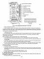
I. Configuration Taps
(See Installation |nstmetions,
for detailed description.)
A. AUX HEAT - Set for heater size (Ex: 0-10 for 10 kw)
B. AC/HP SIZE - Set for size of outdoor unit
C. SYSTEM TYPE - Select "lip COMFORT"
D, AC/HP CFM ADJUST - Select "LO"
E. ON/OFF DELAY - Select "ENH"
TM
AUX HEAT KW/CFM
F. CONTINUOUS
FAN - Select desired speed
2. Install heater with Intelligent Heat Staging, and remove
Jumper J2, except when using 5-, 8-, or 10-kw heater,
3. Remove Jumper J 1 to activate all dehumidify modes.
4. Complete wiring and install outdoor temperature sensor
according to Installation Instructions.
I. Set "DIP Switches" - Set the dip switches (back of Thermidistat
Control Board) appropriately
for specific system being installed.
2. Thermidistat Control Configurations
(See Thermidistat TM Control Installation Instructions for
detailed description,)
• Option 5 (Variable Speed Motors) - set to ON
• Option 7 (Super Dehumidify)
- set to ON
• Option 9 (Intelligent Heat) - set to ON if installing with
a single speed heat pump
• Option 12 (Heaters during Defrost) - setting "2" is
suggested for all heaters
• Option 16 - On R-22 systems set to ON for warmer heat
below 40 ° F. For Puron applications,
set to OFF.
• Option 17 - Select programmable or non-progrmnmable
mode.
3. Set desired humidity level on front of Thermidistat
(50 to 55% RH recommended).
For dehumidification
in
/
cooling, both "dhu" and "cool" must be displayed.
J
HEA_R/MOTOR
MOLEX
12-PIN CONNECTOR
A98510
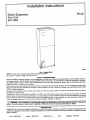
Fig. 20_Set-Up
0 _
CACdI_'
Instructions
7310 W. Mor_s St., I_m,
for Warmer
apo/_s, IN 46231
Heating
imfk4c08
Temperatures
--20--
and Super
Humidity
Bootq'rab:
Control
1/4,3d/2e
in Cooling
Catalog
No. 63FK-4C4