1
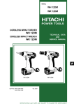
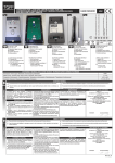
MODEL
NR 90AD
Hitachi
Power Tools
STRIP NAILER
NR 90AD
TECHNICAL DATA
AND
SERVICE MANUAL
N
LIST No. E016
Jun. 2004
SPECIFICATIONS AND PARTS ARE SUBJECT TO CHANGE FOR IMPROVEMENT
REMARK:
Throughout this TECHNICAL DATA AND SERVICE MANUAL, a symbol(s)
is(are) used in the place of company name(s) and model name(s) of our
competitor(s). The symbol(s) utilized here is(are) as follows:
Competitors
Symbols Utilized
Company Name
Model Name
P
Paslode
F-350S
Q
SENCO
FramePro 701XP
CONTENTS
Page
1. PRODUCT NAME ............................................................................................................................. 1
2. MARKETING OBJECTIVE ............................................................................................................... 1
3. APPLICATIONS ................................................................................................................................ 1
4. SELLING POINTS ............................................................................................................................ 1
5. SPECIFICATIONS ............................................................................................................................ 2
5-1. Specifications ..................................................................................................................................... 2
5-2. Explanation of the Nailing Action ....................................................................................................... 3
5-3. Nail Selection ..................................................................................................................................... 4
5-4. Nail Driving Force .............................................................................................................................. 5
6. COMPARISONS WITH SIMILAR PRODUCTS ................................................................................ 6
7. PRECAUTIONS IN SALES PROMOTION ....................................................................................... 7
7-1. Handling Instructions ......................................................................................................................... 7
7-2. Warning Label .................................................................................................................................... 7
7-3. Related Laws and Regulations .......................................................................................................... 8
8. MECHANISM AND OPERATION PRINCIPLE ................................................................................. 9
8-1. Mechanism ........................................................................................................................................ 9
8-2. Operation Principle .......................................................................................................................... 11
9. TROUBLESHOOTING GUIDE ....................................................................................................... 14
9-1. Troubleshooting and Correction ....................................................................................................... 14
9-2. Regrinding the Driver Blade ............................................................................................................. 17
9-3. Possible Causes and Correction of Air Leakage ............................................................................. 18
10. DISASSEMBLY AND REASSEMBLY .......................................................................................... 20
10-1. General Precautions in Disassembly and Reassembly ................................................................. 20
10-2. Disassembly and Reassembly of the Output Section .................................................................... 21
10-3. Disassembly and Reassembly of the Control Valve Section ......................................................... 24
10-4. Disassembly and Reassembly of the Driving Section ................................................................... 27
10-5. Disassembly and Reassembly of the Cap and the Magazine Section .......................................... 30
11. INSPECTION AND CONFIRMATION AFTER REASSEMBLY .................................................... 33
12. STANDARD REPAIR TIME (UNIT) SCHEDULES ....................................................................... 34
Assembly Diagram for NR 90AD
1. PRODUCT NAME
Hitachi 90 mm (3-1/2") Strip Nailer, Model NR 90AD
2. MARKETING OBJECTIVE
The Model NR 90AD is a framing nailer for clipped head (D-head) nails. This is developed as a next-generation
nailer with an all-new design in order to expand our market share. The main features of the Model NR 90AD are
as follows:
(1) Lightweight (3.2 kg) and good balance
(2) Low height
(3) Rapid driving and quick response mechanism
(4) New aggressive appearance
(5) Selective actuation (single actuation/contact actuation)
(6) Tool-less depth adjustment
(7) Comfortable grip
3. APPLICATIONS
Floor and framing
Truss build-up, window build-up
Subflooring and roof decking
Wall sheathing
Mobile home and modular housing construction
4. SELLING POINTS
Lightweight, only 3.2 kg (7.0 lbs.) and good balance
New aggressive appearance
Comfortable grip
Low height
With "single actuation/
contact actuation" selector
Rapid driving and
quick response
Tool-less depth
adjustment
--- 1 ---
5. SPECIFICATIONS
5-1. Specifications
NR 90AD
Model
Driving system
Reciprocating piston type
Operating pressure
5 --- 8.5 kgf/cm2 (70 --- 120 psi, 4.9 --- 8.3 bar) (Gauge pressure)
Driving speed
3 pcs./sec.
Weight
3.2 kg (7.0 lbs.)
Dimensions
(Length x Height x Width)
462 mm x 322 mm x 125 mm
(18-3/16" x 12-11/16" x 4-15/16")
Nail feed system
Spiral spring
Nail capacity
86 nails
Air consumption
2.5 ltr/cycle at 7 kgf/cm2 (0.088 ft3/cycle at 100 psi) (2.5 ltr/cycle at 6.9 bar)
Air inlet
3/8 NPT thread
Packaging
Corrugated cardboard box
Package dimensions
(Length x Height x Width)
587 mm x 398 mm x 136 mm
(23-1/8" x 15-21/32" x 5-11/32")
Standard accessories
Optional accessories
Safety glasses (Code No. 875769) ............................................................ 1
Pneumatic tool lubricant (1 oz oil feeder) (Code No. 877153)
Pneumatic tool lubricant (4 oz oil feeder) (Code No. 874042)
Pneumatic tool lubricant (1 quart can) (Code No. 876212)
Grease (ATTOLUB No. 2) (500 g (1.1 lbs.)) (Code No. 317918)
--- 2 ---
5-2. Explanation of the Nailing Action
To meet the requirements of "ANSI SNT-101-2002", the Model NR 90AD is equipped with a nailing operation
switching device at the valve portion as shown in the figures below. Use SINGLE ACTUATION MECHANISM
(SINGLE SEQUENTIAL ACTUATION MECHANISM) or CONTACT ACTUATION MECHANISM in accordance with
the work to be performed. Each nailing operation is as follows.
SINGLE ACTUATION MECHANISM (SINGLE SEQUENTIAL ACTUATION MECHANISM):
First, press the pushing lever against the wood; next, pull the trigger to drive the nail. First, pull the trigger;
next, press the pushing lever against the wood to drive the nail. After nailing once, nailing will not be possible
again until the trigger is released and pressed again.
CONTACT ACTUATION MECHANISM:
First, press the pushing lever against the wood; next, pull the trigger to drive the nail. First, pull the trigger;
next, press the pushing lever against the wood to drive the nail. If the trigger is held back, a nail will be driven
each time the pushing lever is pressed against the wood.
Nailing operation switching device
Switching device
(Change knob)
Switching device
(Change knob)
SINGLE ACTUATION
MECHANISM
(Switching device:
upward position)
CONTACT ACTUATION
MECHANISM
(Switching device:
downward position)
--- 3 ---
5-3. Nail Selection
The Model NR 90AD utilizes D-head (clipped head) nails collated with paper tape.
Applicable nail dimensions are shown below. Please note that screw-type nails cannot be used with the Model
NR 90AD.
Ensure that nails are as specified in Fig. 1. The Model NR 90AD utilizes D-head (clipped
head) nails collated at an angle of 35 degrees which are the same as the nails utilized by P.
However, some D-head nails made by other makers are collated at a different angle of 26
degrees. Use of such nails will cause clogging of nails and subsequent damage to the
nailer. Also avoid use of misaligned nails or nails collated with a weak paper tape. Do not
use P's 2" Roundrive nail (eccentric full round head nail) with the Model NR 90AD because it
may cause bending of nails. It is recommended to use genuine HITACHI nails to ensure
satisfactory driving quality.
Paper tape collated strip nails D-head (clipped head) nails
Minimum
Maximum
7.7 mm
(0.303")
6.8 mm
(0.266")
90 mm (3-1/2")
50 mm (2")
3.8 mm
(0.148")
Max.
4.6 mm
(0.181")
2.9 mm
(0.113")
35˚
Max.
31.7 mm
(1.248")
CAUTION:
Paper tape
Fig. 1 Dimensions of nail
--- 4 ---
3.8 mm x 90 mm nails
(0.148" x 3-1/2")
5-4. Nail Driving Force
Figure 2 shows by type of wood and nail, the nailer output energy provided by the supply pressure and the nailing
energy required for driving the nail flush. Air pressure which exceeds the intersecting point between the nailer
output energy and the nailing energy required for driving the nail allows the nail to be fully driven.
For example, when driving a nail of 3.3 mm dia. by 90 mm length (0.131" x 3-1/2") into nine sheets of 12 mm
plywood (108 mm thick ) with the Model NR 90AD, a pressure of about 6.8 bar (6.9 kgf/cm2, 99 psi) allows the
nailer to drive the nail flush with the wood surface. A pressure beyond this value causes the nail head to be driven
below the wood surface. Fig. 2 should be used as reference data because those values vary depending on the
type, moisture content, and grain of wood.
Required nailing energy
Nailer output energy
NR 90AD
12 mm (0.47")
plywood x 9
NR 83AA3, P, Q
Fig. 2 Required nailing energy and nailer output energy
--- 5 ---
--- 6 ---
Rear loading (Aluminum)
Rear loading (Aluminum)
Not provided
Rubber
Not provided
2.9 mm --- 3.3 mm
(0.113" --- 0.131")
50 mm --- 83 mm
(2" --- 3-1/4")
Not provided
Rubber
Provided
2.9 mm --- 3.8 mm
(0.113" --- 0.148")
50 mm --- 90 mm
(2" --- 3-1/2")
Direction change of
exhaust air
Handing grip
Single actuation/
contact actuation
selector
Applicable Dia.
nails
(Clip head)
Length
Provided
Not provided
Not provided
Protection of free-fire
50 mm --- 90 mm
(2" --- 3-1/2")
2.9 mm --- 3.8 mm
(0.113" --- 0.148")
Not provided
Rubber
With wrench
With wrench
Not provided
Tool not required
Top loading (Aluminum)
89
86
86
2.5 ltr/cycle
(0.08 ft3/cycle)
Driving depth
adjustment mechanism
Magazine type
Air consumption at
7 kgf/cm2 (100 psi)
Nail capacity
(3-1/4" x 0.131)
2.0 ltr/cycle
(0.07 ft3/cycle)
50 mm --- 90 mm
(2" --- 3-1/2")
2.9 mm --- 3.8 mm
(0.113" --- 0.148")
Not provided
Rubber
Tool not required
Provided
Tool not required
Rear loading (Aluminum)
64
2.6 ltr/cycle
(0.091 ft3/cycle)
380 mm x 333 mm x 107 mm
(14-31/32" x 13-1/8" x 4-1/4")
460 mm x 360 mm x 108 mm
(18-1/8" x 14-3/16" x 4-1/4")
2.1 ltr/cycle
(0.073 ft3/cycle)
488 mm x 333 mm x 130 mm
(19-7/32" x 13-1/8" x 5-1/8")
Dimensions
(L x H x W)
462 mm x 322 mm x 125 mm
(18-3/16" x 12-11/16" x 4-15/16")
3.8 kg (8.4 lbs.)
3.7 kg (8.2 lbs.)
3.9 kg (8.7 lbs.)
3.2 kg (7.0 lbs.)
Weight
5 --- 7 kgf/cm2
(70 --- 100 psi)
5.6 --- 8.5 kgf/cm2
(80 --- 120 psi)
5 --- 8.5 kgf/cm2
(70 --- 120 psi)
Q
5 --- 8.5 kgf/cm2
(70 --- 120 psi)
P
Operating pressure
Model
NR 83AA3
HITACHI
NR 90AD
Maker
6. COMPARISONS WITH SIMILAR PRODUCTS
7. PRECAUTIONS IN SALES PROMOTION
In the interest of promoting the safest and most efficient use of the Model NR 90AD Nailer by all of our customers,
it is very important that at the time of sale the salesperson carefully ensures that the buyer seriously recognizes
the importance of the contents of the Handling Instructions, and fully understands the meaning of the precautions
listed on the Warning Label attached to each tool.
7-1. Handling Instructions
Although every effort is made in each step of design, manufacture, and inspection to provide protection against
safety hazards, the dangers inherent in the use of any pneumatic tool cannot be completely eliminated.
Accordingly, general precautions and suggestions for use of pneumatic tools, and specific precautions and
suggestions for the use of the pneumatic nailer are listed in the Handling Instructions to enhance the safe, efficient
use of the tool by the customer.
Salespersons must be thoroughly familiar with the contents of the Handling Instructions to be able to offer
appropriate guidance to the customers during sales promotion.
7-2. Warning Label
Each Model NR 90AD unit is provided with a Warning Label (illustrated below) which lists basic safety precautions
in its use. Carefully ensure that customers fully understand and follow these precautions before using the tool.
--- 7 ---
7-3. Related Laws and Regulations
As nailers and staplers are designed to instantaneously drive nails and staples, there is an ever-present danger of
misfiring and subsequent possible serious injury. Accordingly, close attention in handling is absolutely necessary
at all times. Carefully ensure that the customer is fully aware of the precautions listed in the Handling Instructions
provided with each unit.
While there are no specific safety regulations, there are related items in various general safety regulations with
which the salespersons should be familiar in order to properly advise the customer. Please check your national
and/or local regulations for applicable items. Some applicable items are outlined below.
The U.S.A:
OSHA
1926.102 Eye and face protection
1926.302 Power-operated hand tools
ANSI SNT-101-2002
Portable, Compressed-Air-Actuated,
Fastener Driving Tools-Safety Requirements for
--- 8 ---
8. MECHANISM AND OPERATION PRINCIPLE
8-1. Mechanism
As illustrated in Fig. 3, the Model NR 90AD can be generally divided into four sections:
Output section, control valve section, driving section and magazine section.
Although the basic construction of the Model NR 90AD is the same as that of the Model NR 90AC3, most of the
parts of the above sections have been newly designed for maximum performance in a strip nailer. Features of the
main parts are described below.
Output section .............. Most of the parts have been newly designed.
(1) The body and exhaust cover are made of aluminum to achieve simplification and
light weight.
(2) The head guard made of stainless steel is mounted to the head.
Control valve section .... Most of the parts have been newly designed.
(1) All the parts except the plunger are made of resin to achieve the light weight.
(2) The entire control valve section is made into a unit type for easy assembly.
(3) The single actuation (single sequential actuation)/contact actuation mechanisms are
the same as that of the Model NR 90AC3.
Driving section .............. Most of the parts have been newly designed.
(1) The basic structure of the depth adjustment mechanism is the same as that of the
Model NV 75AG.
Magazine section ......... Most of the parts have been newly designed.
(1) The magazine is the same rear loading type as the Model NR 83AA3. It is uniquely
shaped and made of aluminum to achieve the light weight.
(2) The magazine cover is integral with the anti-backing ratchet to achieve the light
weight.
--- 9 ---
Head Guard [2]
Exhaust Cover [5]
Head Valve [9]
Control valve section
Output section
Exhaust Valve
Rubber [11]
Cap [41]
Accumulator
Piston [13]
(Driver blade)
Cylinder [15]
Body Ass'y [24]
Driving section
Piston Bumper [31]
on
cti
e
es
zin
a
g
Ma
Nose [29]
Pushing Lever (A) [35]
Control valve section
Valve Piston [66]
Plunger Spring [68]
Valve Bushing (B) [63]
Valve Bushing (A) [71]
Plunger [70]
Switching device
(Change Knob (C) [46])
Trigger (C) [50]
Fig. 3 Construction
--- 10 ---
8-2. Operation Principle
(1) Before nailing (See Fig. 4 and Fig. 5.)
1) When compressed air is fed to the main body, it
fills the accumulator (
Exhaust Valve Rubber [11]
Head valve chamber
Head Valve
Spring [7]
portion).
2) At the same time, the compressed air flows into
Air passage
Head Valve [9]
Control
valve
section
the valve piston lower chamber of the control valve
Accumulator
section and forces the Valve Piston [66] upward.
Piston [13]
Compressed air is then fed through the air supply
vent and air passage to the head valve chamber.
Cylinder hole
Trigger (C) [50]
As a result, the Head Valve Spring [7] is pushed
Cylinder [15]
down to seal the Head Valve [9] and Cylinder [15].
(2) When nailing (See Fig. 4 and Fig. 5.)
Return air chamber
1) When Pushing Lever (A) [35] and Trigger (C) [50]
are operated together and the Plunger [70] is
pushed upward, the compressed air in the valve
piston lower chamber is discharged from the
bottom of the Plunger [70]. As a result, the
compressed air in the accumulator (
Nail
portion)
Pushing Lever (A) [35]
pushes down Valve Piston [66], blocking the air
Fig. 4
supply vent and opening the exhaust valve.
2) When the exhaust valve opens, the compressed
air in the head valve chamber is discharged into
the atmosphere through the air passage.
To the head valve chamber
Air supply vent
Accumulator
3) When the air pressure on the bottom surface of the
Head Valve [9] overcomes the strength of the
Air passage
Head Valve Spring [7], the Head Valve [9] is
pushed upward. At this time, the Head Valve [9]
seals with the Exhaust Valve Rubber [11], blocking
the passage to the exhaust vent.
4) When the Head Valve [9] goes up, the
Exhaust
valve
Valve Piston [66]
Valve piston lower chamber
Plunger [70]
compressed air in the accumulator flows rapidly
into the Cylinder [15], forcing the Piston [13]
Fig. 5 Control valve section
downward to strike the nail. When the Piston [13]
passes the cylinder hole, the compressed air flows
into the return air chamber and is accumulated
there.
--- 11 ---
(3) During return (See Fig. 6 and Fig. 7.)
1) When either Pushing Lever (A) [35] or Trigger (C)
Exhaust vent
Exhaust Valve Rubber [11]
Head valve chamber
Head Valve
Spring [7]
[50] is released, the Plunger [70] goes down and
the compressed air in the accumulator flows into
Air passage
Head Valve [9]
Control
valve
section
the valve piston lower chamber.
Accumulator
2) As the air pressure in the valve piston lower
Cylinder [15]
chamber increases to overcome the air pressure
applied on the upper portion of the Valve Piston
Return air
[66], the Valve Piston [66] is forced upward. When chamber
this occurs, the exhaust valve is closed and the air
supply vent is opened.
Piston [13]
Trigger (C) [50]
Piston Bumper [31]
3) When the air supply vent opens, the compressed
air in the accumulator (
portion) passes
Driver blade
through the air passage and flows into the head
valve chamber to push down the Head Valve [9].
As a result, the Head Valve [9] and the Cylinder
[15] are sealed and, at the same time, the Head
Pushing Lever (A) [35]
Valve [9] and the Exhaust Valve Rubber [11]
Fig. 6
separate to open the exhaust vent.
4) The compressed air above the Piston [13] is
To the head valve chamber
discharged into the atmosphere through the
Air supply vent Accumulator
exhaust vent. In this way, the air pressure above
the Piston [13] is reduced, and the greater
pressure of the air accumulated in the return air
Air passage
chamber pushes the Piston [13] upward.
5) If the air pressure below the Piston [13] is higher
than that of the atmosphere after the Piston [13]
has fully returned, the excess air pressure is
Exhaust
valve
Valve Piston [66]
discharged into the atmosphere through the
clearance between Piston Bumper [31] and the
Valve piston lower chamber
Plunger [70]
Fig. 7 Control valve section
driver blade.
--- 12 ---
(4) Single actuation mechanism/contact actuation mechanism: (Fig. 8 and Fig. 9)
Single/contact actuation mechanism changeover is accomplished by turning the switching device
(Change Knob (C) [46]).
Single actuation mechanism (Switching device:
Accumulator
upward position):
1) Immediately after driving the first nail, the
control valve should be as shown in Fig. 7.
2) When only Pushing Lever (C) [53] is released
Valve Piston [66]
and Trigger (C) [50] is held as shown in Fig. 8,
the plate of Trigger (C) [50] contacts Change
Knob (C) [46] and the Plunger [70] returns
Trigger (C) [50]
Plunger [70]
(lowers) only halfway.
Because of this, compressed air does not flow
Valve piston
lower chamber
into the valve piston lower chamber, and Valve
Piston [66] remains in the lowered position.
Pushing Lever (C) [53]
Accordingly, the Piston [13] remains in the
Switching device (Change Knob (C) [46])
(Upward position)
lowered position as shown in Fig. 6.
3) When Trigger (C) [50] is released, the Plunger
Fig. 8 Single actuation mechanism
[70] returns (lowers) completely as shown in
Fig. 5. Compressed air then flows into the valve
piston lower chamber, and the Valve Piston [66]
is forced upward. The Piston [13] then returns
Accumulator
fully upward. Therefore, unless Trigger (C) [50]
is released after each nailing operation, the
structural mechanism prevents the next nailing
operation.
Valve Piston [66]
Contact actuation mechanism (Switching device:
downward position):
1) Immediately after the first nail is driven, the
Trigger (C) [50]
control valve should be as shown in Fig. 7.
Plunger [70]
2) Even when only Pushing Lever (C) [53] is
released and Trigger (C) [50] is held, the
Valve piston
lower chamber
Plunger [70] returns (lowers) completely as
shown in Fig. 9. Thus the Piston [13] returns
Pushing Lever (C) [53]
Switching device (Change Knob (C) [46])
(Downward position)
(raises) fully. Accordingly, continuous nailing
can be accomplished by pushing only Pushing
Fig. 9 Contact actuation mechanism
Lever (C) [53] up and down while holding
Trigger (C) [50] depressed.
--- 13 ---
9. TROUBLESHOOTING GUIDE
9-1. Troubleshooting and Correction
Problem
Possible cause
1) Nails cannot
be driven.
<Nails>
Magazine is not loaded with
specified genuine nails.
Magazine is loaded with
abnormal nails (bent nails,
large or small round-head
nails, abnormal collation,
etc.).
Inspection method
Check if the magazine is
normally loaded with
specified nails.
Remedy
Use specified nails.
Remove the abnormal nails
and load the magazine with
normal nails.
Nail or collating band clogs.
Collating band is deformed
or torn.
<Magazine>
Magazine is abnormal
(deformed or damaged).
Nail feeder is abnormal
(deformed or damaged).
Ribbon spring is abnormal
(deformed or damaged).
Check if the nail feeder
operates smoothly in the
magazine.
Repair or replace the
defective part.
Check if nails (one strip)
move smoothly in the
magazine.
Nail rail is abnormal
(deformed, burrs, damaged
or fatigued).
Adhesive fragments are on
the nail rail or they need oil.
Remove the adhesive
fragments and apply oil to
the nail feeder, ribbon spring
and the nail rail.
Foreign matter is found on
the guide face of the nail
feeder.
<Nose>
Nail inlet groove of the nose
is abnormal (deformed,
burrs or damaged).
Check if nails (one strip) are
fed smoothly into the nail
injection port of the nose.
Repair or replace the
defective part.
Remove the adhesive
fragments.
Adhesive fragments are in
the nail inlet groove.
--- 14 ---
Problem
Possible cause
Inspection method
Remedy
Pull the nail feeder
backward and perform idle
driving. Check if the driver
blade has returned.
Adjust for 5 to 8.5 kgf/cm2.
Replace the piston O-ring.
<Output section>
Air pressure is too low.
Piston O-ring is worn or
damaged.
Piston bumper is abnormal
(dislocated, deformed or
damaged).
Replace the piston bumper.
O-ring of the cylinder is
abnormal (dislocated,
deformed or damaged).
Reassemble or replace.
Driver blade is abnormal
(deformed, burrs, damaged
or fatigued).
Repair or replace.
Cylinder's internal surface is
abnormal (deposits of dirt or
worn).
Head valve sliding surface is
abnormal (galled, damaged
or needs oil).
Check if nails can be driven
at 5 kgf/cm2.
Head valve spring is
abnormal (fatigued or
damaged).
After operating the nailer
without nails, check if the
driver blade is kept in the
down position.
Replace the head valve
spring.
After making idle driving,
check if the driver blade is
kept in the down position.
Replace the defective part.
O-ring is worn or oiling is
needed.
Disassemble the control
valve and check the O-ring.
Apply grease, or replace.
For short nails, the adjuster
is raised too high.
Check if the adjuster is
raised too high.
Nails are not fully fed into
the injection port.
Unspecified nails are used.
Driver blade is worn.
See item 1).
Turn the adjuster to the
lower position to decrease
the pressure.
See item 1).
<Control valve section>
Plunger, valve piston, valve
bushing (A) or valve bushing
(B) is abnormal (galled or
damaged).
2) Nails are bent
when being
driven.
Workpiece is very hard.
Nail feeder (A) is abnormal
(worn or damaged).
While operating the nailer
without nails, check if the
drivng operation is
performed.
Check if the driver blade tip
is abnormally worn.
Drive a nail into soft wood
workpiece and check if the
nail is bent.
Check nail feeder (A) for
abnormal condition.
--- 15 ---
Remove the dirt and apply
oil, or replace.
Replace the defective part.
Apply grease.
Replace the driver blade.
Do not use unspecified
workpieces.
Replace nail feeder (A).
Problem
3) Head of a nail
driven into a
workpiece
protrudes
from the wood
surface.
Possible cause
Adjuster is improperly
adjusted.
Air pressure is too low.
Workpiece is very hard.
Driver blade is worn.
Piston O-ring is abnormal
(worn or damaged).
Cylinder's internal surface is
abnormal (worn or rough).
4) Nails clog the
mechanism.
Unspecified nails used.
<Improper nail feed>
See <Magazine> in item 1).
Driver blade worn.
Nail feeder (A) is abnormal
(worn or damaged).
<The driver blade has not
returned completely.>
See <Output section> in
item 1).
5) Single
actuation
mechanism is
not possible.
O-ring in plunger is worn.
O-ring in valve piston is
worn.
Abnormal plunger sliding
surface of valve piston
(seized or deformed).
Abnormal plunger, trigger
arm (C), pushing lever (C)
and/or body (worn or
damaged).
The position of a switching
device is mistaken.
Inspection method
Turn the adjuster to the
lowest position and drive a
nail.
Drive a nail into soft wood
workpiece and check if the
head protrudes from the
wood surface.
Operate the nailer without
nails and check if the driver
blade is projected from the
nose tip.
Disassemble the output
section and check the
piston O-ring and the inner/
outer surfaces of the
cylinder for abnormal
condition.
Check if the nails are
specified ones.
Check if they move
smoothly after putting nails,
and check if the nail feeder
operates smoothly.
Remedy
Adjust the adjuster to the
proper position.
Adjust for 5 to 8.5 kgf/cm2.
Do not use unspecified
workpieces.
Replace the driver blade.
Replace the defective part.
Use specified nails.
See <Magazine> in item 1).
Check if the driver blade tip
is worn.
Check nail feeder (A) for
abnormal condition.
Replace the part.
Perform idle driving or
actually drive with nails, and
check if the driver blade has
returned completely.
See <Output section> in
item 1).
Replace nail feeder (A).
Disassemble the control
valve section, and check the
O-ring of the plunger and
the valve piston.
Replace the part.
Check each part for
abnormalities (worn,
damaged, deformed, etc.).
Replace the part.
Replace the part.
Replace the abnormal part.
The position of a switching
device is checked.
--- 16 ---
A switching device is set to
the correct position.
9-2. Regrinding the Driver Blade
The tip of the driver blade should be ground as shown in Fig. 10. To grind with a grinder, gradually grind the tip
while cooling the ground area with water to prevent it from being excessively heated. Excessive grinding will
rapidly reduce the service life of the driver blade. In such a case, replace the driver blade.
Driver blade
Concave
5˚
Grinding surface
Fig. 10
--- 17 ---
9-3. Possible Causes and Correction of Air Leakage
Repair procedure
Air leakage repair location
(1) Check the points of the following parts marked by an
asterisk * for abnormal condition.
(2) Next, check the seal parts marked with a double
circle
for wear, flaw and damage.
(3) And then, check other places.
Control valve section
Possible cause
Air leakage point
With control valve OFF
A) Exhaust port
With control valve ON
The O-ring (I.D 49.4) [8] of the Head Valve
The Exhaust Valve Rubber [11] is abnormal
[9] is abnormal or its sliding surface a is
or the sliding surface c of the Head Valve
worn, deformed or flawed.
[9] is worn or flawed.
The Valve Rubber [14] is abnormal or the
sealing surface b of the Head Valve [9] is
worn or flawed.
B) Exhaust cover
The Hex. Socket Hd. Bolt (W/Flange)
M6 x 30 [4] is loose.
Gasket (A) [6] is damaged.
Seal surface of the Body Ass'y [24] or the
Exhaust Cover [5] is abnormal.
--- 18 ---
Possible cause
Air leakage point
With control valve OFF
With control valve ON
C) Nose 1
The O-ring (S-63) [32] of the Nose [29] or
the groove is abnormal (broken or flawed).
The Nylock Hex. Socket Hd. Bolt M8 x 30
[30] is loose.
D) Nose 2
The O-ring (I.D 94.6) [18] of the Cylinder
The Piston Bumper [31] is abnormal
Plate [17] or the O-ring (I.D. 59.6) [16] of
(portion d is damaged, deformed or
the Cylinder [15] is abnormal (broken or
cracked).
flawed).
The Piston [13] is abnormal (driver blade is
deformed or seal surface is deformed).
E) Control Valve 1
The O-ring (1AP-10) [67] of the Valve
The upper O-ring (P-7) [65] of the Valve
Piston [66] is abnormal (worn, broken or
Piston [66] is abnormal (worn, broken or
flawed).
flawed).
The lower O-ring (P-7) [65] of the Valve
The Feed Piston O-ring (I.D. 14) [62] of
Piston [66] is abnormal (worn, broken or
Valve Bushing (B) [63] is abnormal (broken
flawed).
or flawed).
The O-ring (P-18) [64] of Valve Bushing (B)
The internal surface f of the valve cavity
[63] is abnormal (broken or flawed).
of the Body Ass'y [24] is abnormal.
The internal surface e of the valve cavity
of the Body Ass'y [24] is abnormal.
F) Control Valve 2
G) Cap
The lower O-ring (I.D. 1.8) [69] of the
The upper O-ring (I.D 1.8) [69] of the
Plunger [70] is abnormal (worn, broken or
Plunger [70] is abnormal (worn, broken or
flawed).
flowed).
Valve Bushing (A) [71] is abnormal (sliding
The Valve Piston [66] is abnormal (sliding
surface of the Plunger [70] is deformed or
surface of the Plunger [70] is deformed or
flawed).
flawed).
Gasket (B) [40] is damaged.
The Hex. Socket Hd. Bolt M5 x 16 [42] is loose.
Seal surface of the Body Ass'y [24] or the Cap [41] is abnormal (damaged, deformed or
flawed).
--- 19 ---
10. DISASSEMBLY AND REASSEMBLY
The items particularly necessary for disassembly and reassembly are described below. The [Bold] numbers in
the descriptions below correspond to the item numbers in the Parts List and exploded assembly diagram.
[CAUTION]
Before disassembly or reassembly, be sure to remove all nails and disconnect the air hose from the
nailer (with your finger released from the trigger) to exhaust all the compressed air.
10-1. General Precautions in Disassembly and Reassembly
Apply grease (ATTOLUB No. 2) (Code No. 317918) to the O-rings and the sliding portions.
When installing the O-rings, be careful not to damage the O-rings and prevent dirt entry.
Oil required: Hitachi pneumatic tool lubricant
1 oz (30 cc) oil feeder (Code No. 877153)
4 oz (120 cc) oil feeder (Code No. 874042)
1 quart (1 ltr) can (Code No. 876212)
If Gasket (A) [6] is damaged, replace it and check that no air is leaking.
Be especially careful to prevent the entry of foreign particles into the control valve section.
Use the conventional grip tape for repair of Grip Rubber (A) [38] because Grip Rubber (A) [38] cannot be
mounted without the specifically designed jig.
Tightening torque for each part
Tightening torque N•m (kgf•cm, ft-lb)
Bolt
Nylock Hex. Socket Hd. Bolt M8 x 30 ........................... [30]
30.4
1 (310
Hex. Socket Hd. Bolt M6 x 22 ....................................... [36]
12.7
Hex. Socket Hd. Bolt (W/Flange) M6 x 30 .................... [4]
12.7
Hex. Socket Hd. Bolt (W/Flange) M6 x 12 .................... [78]
9.8
0.8 (100
Hex. Socket Hd. Bolt M5 x 14 ....................................... [1]
8.3
0.5 (85
5, 6.1
0.4)
Hex. Socket Hd. Bolt M5 x 16 ....................................... [42]
6.4
0.5 (65
5, 4.7
0.4)
--- 20 ---
10, 22.4
0.7)
0.8 (130
8, 9.4
0.6)
0.8 (130
8, 9.4
0.6)
8, 7.2
0.6)
10-2. Disassembly and Reassembly of the Output Section
(1) Disassembly and reassembly of the Exhaust Cover [5], Head Valve [9], Exhaust Valve Rubber [11], etc.
(See Fig. 11A and Fig. 11B.)
[Tools required]
Hex. Socket Hd. Bolt
M5 x 14 [1]
Hex. bar wrench (4 mm, 5 mm)
Hammer
Head Guard [2]
(a) Disassembly
Remove the four Hex. Socket Hd. Bolts M5 x 14 [1] with a
Sheet [3]
hex. bar wrench. The Head Guard [2] and the Sheet [3]
Hex. Socket Hd. Bolt
(W/Flange) M6 x 30 [4]
can now be removed.
Remove the four Hex. Socket Hd. Bolt (W/Flange)
M6 x 30 [4] with a hex. bar wrench. The entire Exhaust
Exhaust Cover [5]
Cover [5] can now be removed from the Body Ass'y [24].
As shown in Fig. 11B, insert a 4 to 5 mm dia. bar into the
Head Valve Spring [7]
central hole in the Exhaust Cover [5] and force out the
Exhaust Valve Rubber [11] with a hammer. Now, the
parts forming the Exhaust Valve Rubber [11] can be
O-ring (I.D. 49.4) [8]
taken out.
Head Valve [9]
[CAUTION]
O-ring (I.D. 59.4) [10]
To prevent damage to the Exhaust Valve Rubber [11], do
not use a pointed bar or a bar with a diameter of less
Exhaust Valve Rubber [11]
than 4 mm.
Hammer
Gasket (A) [6]
Exhaust Cover [5]
Bar of 4 to 5 mm dia.
Exhaust Valve
Rubber [11]
Body Ass'y [24]
Fig. 11A Disassembly and reassembly of the
exhaust cover, head valve, exhaust
valve rubber, etc.
--- 21 ---
Fig. 11B
(a) Reassembly
Disassembly procedures should be followed in the reverse order. Note the following points.
Charge the sliding portion of the Head Valve [9] of the Exhaust Cover [5] with about 3 grams of grease and
apply grease to each surface of the O-rings.
As shown in Fig. 12, firmly push the Exhaust Valve Rubber [11] until it is fully seated over the projection of the
Exhaust Cover [5].
Exhaust Valve Rubber [11]
Head Valve [9]
Exhaust Cover [5]
Apply grease of 3 grams
to the sliding potion.
Push until the rubber is fully
seated over the projection.
Fig. 12
Mount the Sheet [3] in the direction as shown in Fig. 13 aligning the center of the hole of the Sheet [3] with the
center of the bolt hole of the Exhaust Cover [5]. If not aligned, abnormal exhaust noise may be heard.
Exhaust Cover [5]
Sheet [3]
Align the center of the hole of
the Sheet [3] with the center
of the bolt hole of the Exhaust
Cover [5].
Fig. 13
--- 22 ---
(2) Disassembly and reassembly of the Cylinder [15], Piston [13], Piston Bumper [31], etc.
(See Fig. 14.)
(a) Disassembly
Remove the Exhaust Cover [5] as described in item (1). Now, the Cylinder [15], Cylinder Plate [17], Piston
[13], Piston Bumper [31], etc. can be taken out.
(b) Reassembly
Disassembly procedures should be followed in the reverse order. Note the following points.
Apply designated grease to the Piston O-ring [12] and the internal side of the Cylinder [15].
Apply designated grease to the O-ring (I.D 94.6) [18], O-ring (I.D 59.6) [16], and then install them.
Valve Rubber [14]
Cylinder [15]
Piston O-ring [12]
Piston [13]
O-ring (I.D 59.6) [16]
Cylinder Plate [17]
O-ring (I.D 94.6) [18]
Cylinder Ring [19]
Face the thick end downward.
Piston Bumper [31]
Body Ass'y [24]
Fig. 14 Disassembly and reassembly of the cylinder, piston, piston bumper, etc.
--- 23 ---
10-3. Disassembly and Reassembly of the Control Valve Section (See Fig. 15.)
[Tools required]
Flat-blade screwdriver
Roll pin puller (3 mm (0.118") dia.)
(a) Disassembly
Remove the Retaining Ring (E-type) for D6 Shaft [22] with blade of a screwdriver and pull out Change Knob
(C) [46] being careful not to lose the Steel Ball D3.97 [44] and Spring (C) [45]. Then, pull out the Roll Pin
D3 x 32 [21] with the roll pin puller (3 mm dia.), remove the Pushing Lever Guide [48], and Trigger (C) [50]
can be removed.
Roll Pin D3 x 25 [20]
Roll Pin D3 x 32 [21]
Carefully disassemble so as
not to lose these parts.
Retaining Ring (E-type)
for D6 Shaft [22]
Feed Piston O-Ring (I.D 14) [62]
Valve Bushing (B) [63]
Steel Ball
D 3.97 [44]
Spring (C) [45]
Body Ass'y [24]
Change Knob (C) [46]
Trigger Arm (C) [47]
O-ring (P-18) [64]
O-ring (P-7) [65]
Valve Piston [66]
O-ring (P-7) [65]
O-ring (1AP-10) [67]
Plunger Spring [68]
O-ring (I.D 1.8) [69]
Plunger [70]
O-ring (I.D 1.8) [69]
Pushing Lever Guide [48]
Valve Bushing (A) [71]
Roll Pin D2.5 x 16 [49]
Roll Pin D3 x 32 [21]
Trigger (C) [50]
Fig. 15 Disassembly and reassembly of the control valve section
--- 24 ---
Pull out the Roll Pins D3 x 25 [20] and
Push
D3 x 32 [21] with the roll pin puller (3 mm
ia. bar
.197") d
7" to 0
m (0.15
4 to 5 m
dia.), and take out the control valve in the
following manner.
Body Ass'y [24]
1) Remove the Exhaust Cover [5] by following
the procedure in (1), item 10-2.
2) As shown in Fig. 16, put in the 4 to 5 mm
(0.157" to 0.197") dia. bar from the upper side
of the Body Ass'y [24] and push the top of
Valve Piston [66]. Now, the parts forming the
control valve can be taken out except Valve
Valve Piston [66]
When disassembling,
do not pull out
this part by gripping
it with the pliers.
Bushing (B) [63].
Valve Bushing (A) [71]
Plunger [70]
[CAUTION]
Be careful not to damage the Valve Piston
[66], Valve Bushings (A) [71] and (B) [63],
Fig. 16
etc.
Do not pull out the end of the Plunger [70]
with the pliers.
Pull out
Valve Bushing (B) [63]
3) To take out Valve Bushing (B) [63], put a 1.5 to
Holes
3 mm (0.059" to 0.118") dia. wire with its end
Be careful not to damage
the internal surface.
hooked into the hole in the bushing and pull it
out while being careful not to damage the
internal surface of Valve Bushing (B) [63], as
shown in Fig. 17.
Wire with 1.5 mm to 3 mm (0.059" to 0.118") dia.
Fig. 17
--- 25 ---
(b) Reassembly
Disassembly procedures should be followed in the reverse order. Note the following points.
Be extremely careful to prevent the entry of foreign particles into the control valve section.
Thoroughly apply grease to the O-Rings (I.D 1.8) [69] of the Plunger [70], the O-Rings (P-7) [65] and
(1AP-10) [67] of the Valve Piston [66].
First, align the roll pin groove of Valve Bushing (A) [71] with that of Valve Bushing (B) [63] and reassemble the
entire control valve unit as shown in Fig. 18. Then install the control valve unit so that the roll pin grooves in
the control valve unit will be aligned with the roll pin holes in the Body Ass'y [24]. First, insert the roll pin puller
(3 mm dia.) into the roll pin holes. Then, upon confirming that the puller passes through the hole, drive in the
Roll Pins D3 x 25 [20] and D3 x 32 [21].
If an attempt is made to drive the roll pin with force when the roll pin grooves in Valve Bushings (A) [71] and
(B) [63] is not aligned with the roll pin holes in the Body Ass'y [24], it will damage the periphery of Valve
Bushing (A) [71] and (B) [63], and prevent disassembly or reassembly.
Roll pin groove in
Valve Bushing (A) [71]
Align
Roll pin groove in
Valve Bushing (B) [63]
Body Ass'y [24]
Roll pin holes
Roll Pin D3 x 25 [20]
Roll Pin D3 x 32 [21]
Roll pin groove
Roll pin groove
Fig. 18
After assembly, make sure that the Plunger [70] moves smoothly.
--- 26 ---
10-4. Disassembly and Reassembly of the Driving Section (See Fig. 19.)
[Tools required]
Hex. bar wrench (5 mm and 6 mm)
Roll pin puller (2.5 mm (0.098") dia.)
Wrench M6
(1) Disassembly and resassembly of Nose [29], Pushing Lever (A) [35] and other parts
(a) Disassembly
Holding the Nylon Nut M6 [74] with a wrench M6, remove the Hex. Socket Hd. Bolt M6 x 22 [36] and pull out
the entire magazine section backward.
Remove the Hex. Socket Hd. Bolt M5 x 14 [1] and take out Pushing Lever Cover (A) [28].
Remove the Nylock Hex. Socket Hd. Bolt M8 x 30 [30], then the Nose [29], Pushing Lever (A) [35] and others
can be removed.
Nylon Nut M6 [74]
Hex. Socket Hd. Bolt
M6 x 22 [36]
Handle Arm [73]
Body Ass'y [24]
Piston Bumper [31]
O-ring (S-63) [32]
Roll Pin
D3 x 32 [21]
Magazine section
Washer [27]
Pushing Lever Guide [48]
Pushing Lever Spring (B) [51]
Pushing Lever Spring (A) [52]
Hex. Socket
Hd. Bolt
M5 x 14 [1]
Pushing Lever (C) [53]
Adjuster [54]
Roll Pin D2 x 16 [55]
Pushing Lever
Cover (A) [28]
Adjuster Spring [56]
Nylock Hex. Socket
Hd. Bolt M8 x 30 [30]
Adjuster Plate (C) [57]
Adjuster Plate (A) [58]
Nose [29]
Pushing Lever (B) [59]
O-ring (S-5) [60]
Retaining Ring (E-type)
for D3 Shaft [61]
Pushing Lever (A) [35]
Nylon Nut M5 [33]
Nose Rubber [34]
Fig. 19 Disassembly and reassembly of the driving section
--- 27 ---
(b) Reassembly (See Fig. 20.)
Disassembly procedures should be followed in the reverse order. Note the following points.
Apply grease to the O-ring (S-63) [32] and mount it in the groove of the Nose [29].
Insert Pushing Lever Springs (A) [52] and (B) [51] between the protrusion of Pushing Lever (C) [53] and the
protrusion of the Pushing Lever Guide [48].
Align the bent portion of Adjuster Plate (A) [58] with the concave portion of the Pushing Lever Guide [48].
After reassembly, check the components of the pushing lever and the Adjuster [54] move smoothly.
Pushing Lever (C) [53]
Pushing Lever Spring (A) [52]
Pushing Lever Spring (B) [51]
Adjuster [54]
Protrusions
Pushing Lever Guide [48]
Align these portions.
Bent portion of Adjuster Plate (A) [58]
Fig. 20
Be careful of the mounting direction of the Nose Rubber [34]. As shown in Fig. 21, mount the two Nose
Rubbers [34] so that their convex portions face downward.
Nose Rubbers [34]
Nose [29]
Nose Rubber [34]
Fig. 21
--- 28 ---
Mount the Nose Rubbers [34]
so that these convex portions
face downward.
(2) Disassembly and reassembly of the adjuster unit
(a) Disassembly (See Fig. 22.)
Remove the Retaining Ring (E-type) for D3 Shaft [61]. Then Pushing Lever (A) [35] and the adjuster unit can
be separated.
Pull out the Roll Pin D2 x 16 [55]. Then the adjuster unit can be disassembled.
(b) Reassembly
Disassembly procedures should be followed in the reverse order. Note the following points.
Mount Adjuster Plate (A) [58] facing its bent portion toward the Adjuster [54].
Mount Adjuster Plate (C) [57] facing its convex portion toward Adjuster Plate (A) [58].
Adjuster [54]
Adjuster Plate (C) [57]
Convex portion
Adjuster Spring [56]
Bent portion
Bent portion
Adjuster Plate (A) [58]
Fig. 22
--- 29 ---
10-5. Disassembly and Reassembly of the Cap and the Magazine Section
(1) Magazine [77], Nail Feeder Ass'y [88] and the related parts (See Fig. 23.)
[Tools required]
Hex. bar wrench (5 mm)
Wrench M6
Roll pin puller (3 mm (0.118") dia.)
Wooden hammer
(a) Disassembly
Holding the Nylon Nut M6 [74] with a wrench M6, remove the Hex. Socket Hd. Bolt M6 x 22 [36] and pull out
the entire magazine section backward.
Pull out the Roll Pin D3 x 8 [86] with a roll pin puller (3 mm dia.) and remove the Nail Feeder Ass'y [88],
Ribbon Spring [83] and Needle Roller D4 x 20 [82] from the front of the Magazine [77].
Remove the three Hex. Socket Hd. Bolts (W/Flange) M6 x 12 [78]. Then the Handle Arm [73] and the
Magazine Cover [76] can be removed together with the other parts.
The Nail Rail [84] that is press-fitted into the Magazine [77] has a protrusion at the rear end to prevent coming
off. Tap at the front of the Magazine [77] using a hammer and a bar being careful not to scratch the parts.
(b) Reassembly
Disassembly procedures should be followed in the reverse order. Note the following points.
Insert the Nail Rail [84] from the rear of the Magazine [77] and press-fit the Nail Rail [84] into the Magazine
[77] by tapping with a wooden hammer so that the rear end of the Nail Rail [84] becomes flush with the
Magazine [77].
Hook the hook of the Ribbon Spring [83] on the Magazine [77] then mount the Nail Feeder Ass'y [88] to the
Magazine [77]. Then insert the Roll Pin D3 x 8 [86].
Holding the Nylon Nut M6 [74] with a wrench M6, mount the magazine section to the Body Ass'y [24] with the
Hex. Socket Hd. Bolt M6 x 22 [36].
--- 30 ---
Sleeve [75]
Nylon Nut M6 [74]
Magazine Cover [76]
Rear
Hold it with a wrench M6 when
tightening or removing the Hex.
Socket Hd. Bolt M6 x 22 [36].
Hex. Socket Hd.
Bolt M6 x 22 [36]
Nylon Nut M6 [74]
Protrusion
Handle Arm [73]
Nylon Nut M6 [74]
Nail Rail [84]
Hex. Socket Hd.
Bolt (W/Flange)
M6 x 12 [78]
Needle Roller
D4 x 20 [82]
Hooking portion
Nail Feeder Ass'y [88]
Roll Pin D3 x 8 [86]
Ribbon Spring [83]
Front
Hook
Fig. 23
(2) Nail Feeders (A) [79], (B) [81] and the related parts (See Fig. 24.)
[Tool required]
Roll pin puller (4 mm (0.157") dia.)
(a) Disassembly
Fix the Nail Feeder Ass'y [88] using a V-block and pull out the Roll Pin D4 x 32 [80] from the top using a roll
pin puller (4 mm (0.157") dia.). Then Nail Feeder (A) [79], Nail Feeder (B) [81] and Feeder Spring [85] can
be removed.
Remove Nail Feeder (A) [79] from Nail Feeder (B) [81] by twisting Nail Feeder (A) [79].
--- 31 ---
(b) Reassembly
Disassembly procedures should be followed in the reverse order. Note the following points.
When inserting the Roll Pin D4 x 32 [80] into Nail Feeder (B) [81], be careful that the end of the Roll Pin
D4 x 32 [80] is not stick out from Nail Feeder (B) [81]. Insert the Feeder Spring [85] between the protrusion of
Nail Feeder (A) [79] and the protrusion of Nail Feeder (B) [81].
Protrusion
Roll Pin D4 x 32 [80]
Nail Feeder Ass'y [88]
Nail Feeder (A) [79]
Nail Feeder (B) [81]
Feeder Spring [85]
Protrusion
Fig. 24
(3) Disassembly and reassembly of the cap (See Fig. 25.)
[Tool required]
Hex. bar wrench (4 mm)
(a) Disassembly
Remove the three Hex. Socket Hd. Bolts M5 x 16 [42], then the Cap [41] and Gasket (B) [40] can be
removed.
(b) Reassembly
Reassembly can be accomplished by following the disassembly procedures in reverse.
Hex. Socket Hd. Bolt
M5 x 16 [42]
Cap [41]
Gasket (B) [40]
Body Ass'y [24]
Fig. 25
--- 32 ---
11. INSPECTION AND CONFIRMATION AFTER REASSEMBLY
Check that Nail Feeder (B) [81] slides in the Magazine [77] smoothly.
Check that the Plunger [70] moves smoothly.
Check that Adjuster [54] turns smoothly by hand.
Check that there is no air leakage from each part.
Set Change Knob (C) [46] to "contact actuation" (see 5-2). While driving nails with an air pressure of
5 kgf/cm2 (71 psi), check that there is no misfiring and bending of nails.
Note: Before conducting the driving test, turn the Adjuster [54] to the deepest position.
Set Change Knob (C) [46] to "single actuation (single sequential actuation)" (see 5-2). Check that the Model
NR 90AD operates by pressing Pushing Lever (A) [35] against a test piece first then pulling Trigger (C) [50].
Check that the Piston [13] is still showing from the Nose [29] tip (outlet of nails) after Pushing Lever (A) [35] is
released from the test piece with Trigger (C) [50] pulled.
Recheck the tightening torque of each screw.
Check that Pushing Lever (A) [35] slides smoothly.
Check that the machine will not operate only by pulling Trigger (C) [50]. Also check that the machine will not
operate only by depressing Pushing Lever (A) [35].
--- 33 ---
12. STANDARD REPAIR TIME (UNIT) SCHEDULES
MODEL
Variable
Fixed
10
20
30
40
50
60 min.
Work Flow
NR 90AD
Exhaust Cover
Head Valve
Spring
Nose
O-ring x 2
Nail Feeder
Head Valve
Ass'y
Exhaust Valve
Magazine Cover
Rubber
Magazine
Nail Feeder (A)
Nail Feeder (B)
Ribbon Spring
General Assembly
Pushing Lever
(A)
Pushing Lever
Guide
Trigger (C)
Plunger Spring
(B)
Plunger Spring
(A)
Pushing Lever
(C)
Adjuster
Pushing Lever
(B)
O-ring
Cylinder
Valve Rubber
O-ring x 2
Cylinder Plate
Cylinder Ring
Valve Bushing
(B)
Feed Piston
O-ring
O-ring x 6
Valve Piston
Plunger Spring
Plunger
Valve Bushing
(A)
Change Knob
(C)
Spring (C)
Piston
Piston O-ring
Piston Bumper
O-ring
Adjustment
(Cylinder,
Body, Valve)
--- 34 ---
Body Ass'y
Hitachi Power Tools
LIST NO. E016
PNEUMATIC TOOL PARTS LIST
STRIP NAILER
Model NR 90AD
2004
•
6 • 15
(E1)
PARTS
ITEM
NO.
1
NR 90AD
CODE NO.
DESCRIPTION
NO.
USED
949-665
HEX. SOCKET HD. BOLT M5X14 (10 PCS.)
5
2
884-952
HEAD GUARD
1
3
884-986
SHEET
1
4
878-877
HEX. SOCKET HD. BOLT (W/FLANGE) M6X30
4
5
884-951
EXHAUST COVER
1
6
884-953
GASKET (A)
1
7
884-949
HEAD VALVE SPRING
1
8
884-947
O-RING (I.D 49.4)
1
9
884-946
HEAD VALVE
1
10
884-948
O-RING (I.D 59.4)
1
11
884-950
EXHAUST VALVE RUBBER
1
12
884-958
PISTON O-RING
1
13
884-957
PISTON
1
14
884-945
VALVE RUBBER
1
15
884-941
CYLINDER
1
16
884-942
O-RING (I.D 59.6)
1
17
884-944
CYLINDER PLATE
1
18
884-943
O-RING (I.D 94.6)
1
REMARKS
19
877-317
CYLINDER RING
1
20
949-539
ROLL PIN D3X25 (10 PCS.)
1
21
884-975
ROLL PIN D3X32
2
22
955-479
RETAINING RING (E-TYPE) FOR D6 SHAFT
1
NAME PLATE
1
884-940
BODY ASS’Y
1 INCLUD. 37, 38
23
24
25
884-956
PROTECTOR
1
27
876-205
WASHER
1
28
884-976
PUSHING LEVER COVER (A)
1
29
884-961
NOSE
1
30
306-437
NYLOCK HEX. SOCKET HD. BOLT M8X30
4
31
884-959
PISTON BUMPER
1
32
884-960
O-RING (S-63)
1
33
877-371
NYLON NUT M5
1
34
884-985
NOSE RUBBER
2
35
884-970
PUSHING LEVER (A)
1
36
949-670
HEX. SOCKET HD. BOLT M6X22 (10 PCS.)
1
37
884-987
GRIP RUBBER (B)
1
38
GRIP RUBBER (A)
1 SUPPLIED WITH ITEM NO. 601, 602
39
HITACHI LABEL
1
40
883-678
GASKET (B)
1
41
884-954
CAP
1
42
949-821
HEX. SOCKET HD. BOLT M5X16 (10 PCS.)
3
43
872-035
DUST CAP
1
44
959-155
STEEL BALL D3.97 (10 PCS.)
1
45
982-454
SPRING (C)
1
46
884-968
CHANGE KNOB (C)
1
47
884-988
TRIGGER ARM (C)
1
48
884-969
PUSHING LEVER GUIDE
1
49
881-951
ROLL PIN D2.5X16
1
50
884-967
TRIGGER (C)
1 INCLUD. 47, 49
51
883-302
PUSHING LEVER SPRING (B)
1
52
883-305
PUSHING LEVER SPRING (A)
1
--- 2 ---
* ALTERNATIVE PARTS
6 -- 04
PARTS
ITEM
NO.
53
NR 90AD
CODE NO.
884-972
NO.
USED
DESCRIPTION
PUSHING LEVER (C)
REMARKS
1
54
884-974
ADJUSTER
1
55
880-093
ROLL PIN D2X16
1
56
882-890
ADJUSTER SPRING
1
57
884-973
ADJUSTER PLATE (C)
1
58
882-886
ADJUSTER PLATE (A)
1
59
884-971
PUSHING LEVER (B)
1
60
872-822
O-RING (S-5)
1
61
872-971
RETAINING RING (E-TYPE) FOR D3 SHAFT
1
62
877-763
FEED PISTON O-RING (I.D.14)
1
63
884-963
VALVE BUSHING (B)
1
64
873-570
O-RING (P-18)
1
65
676-531
O-RING (P-7)
2
66
884-964
VALVE PISTON
1
67
872-654
O-RING (1AP-10)
1
68
884-966
PLUNGER SPRING
1
69
878-888
O-RING (I.D 1.8)
2
70
884-965
PLUNGER
1
71
884-962
VALVE BUSHING (A)
1
73
884-984
HANDLE ARM
1
74
963-837
NYLON NUT M6
4
75
883-499
SLEEVE
1
76
884-979
MAGAZINE COVER
1
77
884-977
MAGAZINE
1
78
984-443
HEX. SOCKET HD. BOLT (W/FLANGE) M6X12
3
79
884-981
NAIL FEEDER (A)
1
80
949-682
ROLL PIN D4X32 (10 PCS.)
1
81
884-982
NAIL FEEDER (B)
1
82
943-364
NEEDLE ROLLER D4X20
1
83
883-503
RIBBON SPRING
1
84
884-978
NAIL RAIL
1
85
884-983
FEEDER SPRING
1
86
949-749
ROLL PIN D3X8 (10 PCS.)
1
87
884-955
LABEL (B)
1
88
884-980
NAIL FEEDER ASS’Y
1 INCLUD. 79-81, 85
LABEL (C)
1
89
6 -- 04
* ALTERNATIVE PARTS
--- 3 ---
NR 90AD
STANDARD ACCESSORIES
ITEM
NO.
501
CODE NO.
875-769
DESCRIPTION
SAFETY GLASSES
NO.
USED
REMARKS
1
OPTIONAL ACCESSORIES
ITEM
NO.
601
602
--- 4 ---
CODE NO.
DESCRIPTION
NO.
USED
881-768
GRIP TAPE (A)
1
880-407
TAPE
1
* ALTERNATIVE PARTS
REMARKS
Printed in Japan
(040615N)
6 -- 04