1
Analyzer Specifications
Specifications
2.2 Analyzer Specifications
The System One analyzer contains two independent voltmeters. The
“READING” meter displays the selected measurement mode and has the
greatest sensitivity and dynamic range. The “LEVEL” meter monitors the
wideband-input signal following input attenuation and pre-amplification,
before subsequent signal processing filtering, and additional gain stages.
Its most sensitive range is 80 mV, limiting full performance to inputs
>10 mV (-38 dBu). In the 2-CHANNEL and CROSSTALK modes, the
LEVEL meter displays the amplitude of the alternate input (SYS-22 and
SYS-02 only), thus enabling simultaneous amplitude measurements on
both input channels.
Inputs are fully differential (balanced) with female XLR (pin 2 high)
and dual banana jack connectors. (Specify Option LXPH to substitute a
1/4-in. stereo phone jack for the XLR.) An additional unbalanced and
switchable Auxiliary input (Channel A only) is provided for special
applications.
Amplitude can be displayed in Vrms, dBV (1.000 Vrms ref), dBu
(0.7746 Vrms ref), dBr with respect to any predefined or measured
reference, or dBm/watts computed into any arbitrary resistance. The
READING meter has selectable rms, average, peak, Q-peak (per CCIR
Rec 468-3), and S-peak detectors; the LEVEL meter detector is rms only.
Measurement resolution is approx 0.004% (1/25200) of range at “4/s,”
varying to 0.032% (1/3150) at “32/s.” All displays are rounded to four
digits or 0.01 dB.
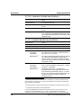
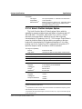
2.2.1 Input Related
Impedance
100 kΩ ±1%, shunted by 270 pF each side to ground.
5
Selectable 600 – 150 Ω (±1%) terminations.
Maximum Rated Input
200 Vpeak, 140 Vrms on main inputs; 100 Vpeak on
auxiliary input. 1 W (+30 dBm) with terminations.
Common-Mode Rejection
Ratio
70 dB, 50 Hz – 20 kHz, Vin <2 V;
50 dB, 50 Hz – 1 kHz, Vin >2 V.
5
Specify Option EURZ to substitute 300 Ω for the 150 Ω termination selection.
System One Description/Installation/APWIN Guide
2-3