1
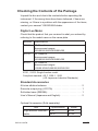
User’s
Manual
51011/51012/51021
Digital Lux Meter
Keep this manual in a safe place so that
you can refer to it when necessary.
IM 51011-01EN
2nd Edition: Oct. 2013 (YMI)
Thank you for purchasing the digital lux meter.
This user’s manual primarily explains the handling precautions and
basic operations of the digital lux meter.
To ensure correct use, please read this manual thoroughly before
beginning operation.
After reading this manual, keep it in a safe place.
Notes
• The contents of this manual are subject to change without prior
notice as a result of continuing improvements to the instrument’s
performance and functionality. The figures given in this manual
may differ from the actual screen.
• Every effort has been made in the preparation of this manual to
ensure the accuracy of its contents. However, should you have
any questions or find any errors, please contact your nearest
YOKOGAWA dealer.
• Copying or reproducing all or any part of the contents of this
manual without the permission of YOKOGAWA is strictly
prohibited.
Trademarks
• Adobe, Acrobat, and PostScript are either registered trademarks
or trademarks of Adobe Systems Incorporated.
• In this manual, the ® and TM symbols do not accompany their
respective registered trademark or trademark names.
• Other company and product names are registered trademarks
or trademarks of their respective companies.
IM 51011-01EN
1
Revisions
• February 2013 1st Edition
• October 2013 2nd Edition
2ndEdition: October 2013 (YMI)
All Rights Reserved, Copyright © 2013,
Yokogawa Meters & Instruments Corporation
Printed in Japan
2
IM 51011-01EN
Checking the Contents of the Package
Unpack the box and check the contents before operating the
instrument. If the wrong items have been delivered, if items are
missing, or if there is a problem with the appearance of the items,
contact your nearest YOKOGAWA dealer.
Digital Lux Meter
Check that the product that you received is what you ordered by
referring to the model name on the name plate.
MODEL
Specifications
51011
JIS Class A
Measurement ranges:
99.9/999/9,990/99,900/999,000
51012
JIS Class AA
Measurement ranges:
99.9/999/9,990/99,900/999,000
51021
JIS Class AA
Measurement ranges:
9.99/99.9/999/9,990/99,900/999,000
51011, 51012: Single-function model
Compliant standard: JIS C 1609-1: 2006
(JIS: Japanese Industrial Standards)
Standard Accessories
AA-size alkaline batteries . . . . . . . . . . . . . . . . . . . . . . . . . . . . 2
Recorder output plug (JC017A) . . . . . . . . . . . . . . . . . . . . . . . 1
Soft-sided case (RB038A) . . . . . . . . . . . . . . . . . . . . . . . . . . . 1
User’s Manual (Japanese and English) . . . . . . . . . . . . . . . . . 2
Optional Accessories (Sold separately)
Item
Light-detector extension
cable
IM 51011-01EN
Specifications
Model
3m
91001
30 m
91002
3
Safety Precautions
The general safety precautions described herein must be observed
during all phases of operation. If the instrument is used in a
manner not specified in this manual, the protection provided by
the instrument may be impaired. YOKOGAWA assumes no liability
for the customer’s failure to comply with these requirements.
The following symbols are used on this instrument.
Warning: handle with care. Refer to the user’s manual
or service manual. This symbol appears on dangerous
locations on the instrument which require special
instructions for proper handling or use. The same symbol
appears in the corresponding place in the manual to
identify those instructions.
Make sure to comply with the precautions below.
Not complying might result injury or death.
WARNING
Use the instrument Only for Its Intended Purpose
The lux meter is for measuring illuminances.
Do not use this meter for any other purpose.
Check the Physical Appearance
Do not use the meter if there is a problem with its physical appearance.
Do Not Disassemble
Only qualified YOKOGAWA personnel may disassemble this product.
Do Not Operate in an Explosive Atmosphere
Do not use this meter in the presence of flammable gases or vapors.
Doing so is extremely dangerous.
4
IM 51011-01EN
CAUTION
• The meter is for domestic use (Class B) and meets the
electromagnetic compatibility requirements.
• Do not drop the meter or strike it against hard objects.
• Avoid storing the meter in direct sunlight or in a humid environment.
• Using the meter in an low-temperature environment (–10°C to 0°C)
may slow down the display’s response.
• Avoid using the meter in a dirty or dusty environment or in an
environment with salt or corrosive gases.
• Do not wipe the meter with organic solvents.
Dirt or dust adhering to the light-detecting surface of the meter
decreases measurement accuracy.
Wipe the surface clean with a soft, dry cloth.
• Do not separate the light-detector from the main unit with the power
on.
IM 51011-01EN
5
Conventions Used in This Manual
Notes and Cautions
The notes and cautions in this manual are categorized using the
following symbols.
Improper handling or use can lead to injury to
the user or damage to the instrument.
This symbol appears on the instrument to
indicate that the user must refer to the
user's manual for special instructions.
WARNING Calls attention to actions or conditions that
could cause serious or fatal injury to the user,
and precautions that can be taken to prevent
such occurrences.
CAUTION Calls attention to actions or conditions that could
cause light injury to the user, or cause damage
to the instrument or user’s data, and precautions
that can be taken to prevent such occurrences.
Note 6
Calls attention to information that is important for
the proper operation of the instrument.
IM 51011-01EN
Measurement Category
WARNING
• Do not use the meter for measurements in locations falling
that fall under Measurement Categories II, III, and IV.
• Do not use the meter to measure voltage or current.
The meter is designed for measurement category I:
EN 61010-1: 2001
Measurement
Category
Description
Remarks
CAT I
For measurement performed on
circuits not directly connected to
MAINS.
CAT I: EN 61010-1: 2001
Circuits not connected
to a mains power
source.
CAT II
For measurement performed on
circuits directly connected to
the low-voltage installation.
Appliances, portable
equipment, etc.
CAT III
For measurement performed in
the building installation.
Distribution board,
circuit breaker, etc.
CAT IV
For measurement performed at
the source of the low-voltage
installation.
Overhead wire,
cable systems, etc.
IM 51011-01EN
7
Contents
Checking the Contents of the Package . . . . . . . . . . . . . . . . . . . . . 3
Safety Precautions . . . . . . . . . . . . . . . . . . . . . . . . . . . . . . . . . . . . . 4
Conventions Used in This Manual . . . . . . . . . . . . . . . . . . . . . . . . . 6
Measurement Category . . . . . . . . . . . . . . . . . . . . . . . . . . . . . . . . . 7
1. Component Names and Functions . . . . . . . . . . . . . . . . . . . . . . . 9
2. Before Operation . . . . . . . . . . . . . . . . . . . . . . . . . . . . . . . . . . . 14
2.1 Measurement Functions . . . . . . . . . . . . . . . . . . . . . . . . . . 14
2.2 Turning the Power On and Off . . . . . . . . . . . . . . . . . . . . . 14
2.3 Setting the Response . . . . . . . . . . . . . . . . . . . . . . . . . . . . 15
2.4 Checking and Replacing Batteries . . . . . . . . . . . . . . . . . . 16
2.5 Automatic Power Off . . . . . . . . . . . . . . . . . . . . . . . . . . . . . 16
2.6 Notes on Illuminance Measurement . . . . . . . . . . . . . . . . . 18
3. Normal Illuminance Measurement . . . . . . . . . . . . . . . . . . . . . . 19
4. Color Correction Measurement (K Key) . . . . . . . . . . . . . . . . . . 20
5. Timer Hold (HOLD and T-H Keys) . . . . . . . . . . . . . . . . . . . . . . 22
6. Range Hold (RANGE Key) . . . . . . . . . . . . . . . . . . . . . . . . . . . . 24
7. Average Illuminance (AVG Key) . . . . . . . . . . . . . . . . . . . . . . . . 25
8. Deviation Display (Δ/% Key) . . . . . . . . . . . . . . . . . . . . . . . . . . . 27
9. Light Source Luminous Intensity (cd Key) . . . . . . . . . . . . . . . . 28
10. Totalized Intensity of Illumination (ACC Key) . . . . . . . . . . . . . 29
11. Comparator (COMP Key) . . . . . . . . . . . . . . . . . . . . . . . . . . . . 32
12. Ripple Measurement (S-F Key) . . . . . . . . . . . . . . . . . . . . . . . 33
13. Communication Functions . . . . . . . . . . . . . . . . . . . . . . . . . . . 36
13.1 Cable Connection and Interface Specifications . . . . . . . 36
13.2 List of Commands . . . . . . . . . . . . . . . . . . . . . . . . . . . . . . 37
13.3 Detailed Description of Commands . . . . . . . . . . . . . . . . 38
14. Recorder Output (Analog Output) . . . . . . . . . . . . . . . . . . . . . . 41
15. Separating the Light Detector . . . . . . . . . . . . . . . . . . . . . . . . . 42
16. Supplying Power through USB . . . . . . . . . . . . . . . . . . . . . . . . 42
17. After-Sales Service . . . . . . . . . . . . . . . . . . . . . . . . . . . . . . . . . 43
17.1 Error Messages . . . . . . . . . . . . . . . . . . . . . . . . . . . . . . . . 43
17.2 Calibration . . . . . . . . . . . . . . . . . . . . . . . . . . . . . . . . . . . . 43
18. Specifications . . . . . . . . . . . . . . . . . . . . . . . . . . . . . . . . . . . . . 44
19. Characteristics of Relative Visible-spectrum Response . . . . . 49
20. Characteristic of Oblique Incident Light . . . . . . . . . . . . . . . . . 51
21. Illuminance Measurement Method . . . . . . . . . . . . . . . . . . . . . 52
22. "Measure for Administration of the Pollution Control of
Electronic Information Product" of China . . . . . . . . . . . . . . . . 55
8
IM 51011-01EN
1. Component Names and Functions
Cap
Protects the
light-detecting surface
Used also during
automatic
zero adjustment
Light detector
Can be separated
from the main unit
(using an extension
cable)
Light-detecting surface
Main unit
Display
POWER key
Turns the power
on and off
Keys
Hand strap
USB port
(mini B type)
Use the USB cable
to communicate to the PC
and supply power.
IM 51011-01EN
9
Keys
51011/51012
(single-function model)
51021
POWER
ON/OFF
RANGE
T-H
CALL
Δ/%
1
K
2
AVG
COMP
3
cd
4
ACC
C
SET
POWER
ON/OFF
RANGE
T-H
Δ/%
S-F
>
RANGE Key
Use this key to switch the range.
Press the key to switch to manual range mode.The range changes
each time you press the key.To return to auto range mode, hold the
key down for at least 1 second.
T-H Key
Use this key to set the timer hold-time or start the timer.
CALL Key
Use this key to view settings.
Values (shown below) that are relevant to the measurement
function that you are using are displayed while you hold the key
down.
Color correction factor, intensity measurement distance, high and
low comparator limits, and ripple ratio
Δ/% Key
Use to display deviation.
Press the key to display the deviation or percentage of
measurement data in reference to a reference value.
To return to the normal luminance measurement, hold the key
down for at least 1 second.
K Key
Use this key in color correction measurement.
Color corrected results are displayed.
A switch is made between normal measurement and color
correction measurement each time you press this key.
You can also set the color correction factor.
10
IM 51011-01EN
AVG Key
Use this key in average illuminance measurement.
To return to the normal illuminance measurement, hold the key
down for at least 1 second.
1, 2, 3, 4, and C Keys
Use this key in average illuminance measurement.
You can store location data for the 4-point method and 5-point
method.
(Location number display: 1 2 3 4 C )
COMP Key
Use this key to set the high and low comparator limits and to start
the comparator function.
To return to the normal illuminance measurement, hold the key
down for at least 1 second.
cd Key
Use this key to set the light intensity distance and to display the
intensity.
A switch is made between normal measurement and light source
intensity measurement each time you press the key.
ACC Key
Use this key to set the limit for the totalized intensity of illumination
and to display the integral time and integral value.
To return to the normal illuminance measurement, hold the key
down for at least 1 second.
S-F Key
Use this key in ripple measurement.
A switch is made between normal measurement and ripple
measurement each time you press the key.
SET Key
Use this key to configure various settings.
Key and
Key
Use these keys to move the setting position and change values.
IM 51011-01EN
11
Measurement reference
plane indication
Tripod-mounting screw
Recorder output
connector
Connect to a
recorder or
oscilloscope with
a dedicated
cable.
Eject button
Used to separate
the light detector
from the main unit
Hold switch
Holds the measured
data reading
12
Battery cover
Response selector
switch
Switches the light
detector response speed
between FAST and SLOW
IM 51011-01EN
Display
AUTO POWER OFF RCD COMP Lo Go Hi
CALL
SET
K S-F
R-H D-H
fc S
lx h
% m
cdft
AVG MEMO 1 2 3 4 C RSPS S F
*: When every element is showing (some elements are not used)
Element
8,8.8.8,8.8.8
AUTO POWER OFF
Description
Digital display of measured, calculated, and set values
Lights in automatic power-off mode
Deviation
CALL
Lights when CALL is pressed
SET
Lights in setting mode
K
Color correction factor
RCD
Lights when a plug is inserted into the recorder output
connector
S-F
Ripple measurement
COMP Lo Go Hi
Lights in comparator mode
R-H
Lights in range hold mode
D-H
Lights in data hold and timer hold modes
Lights when the battery voltage is low
AVG-MEMO- 1 2 3 4 C Lights during average illuminance
RSPS S F
Response setting
S
Timer hold-time unit (seconds)
lx
Unit for illuminance measurement
h
Unit for integral time of totalized intensity of illumination
%
Deviation display %
m
Unit for the distance to the light source
cd
Unit for luminous intensity; lights during light source
luminous intensity measurement
IM 51011-01EN
13
2. Before Operation
2.1 Measurement Functions
The meter has the following measurement functions.
51011
51012
Single-function model
• Normal luminance measurement
• Deviation display
• Normal luminance measurement
• Deviation display
• Color correction luminance measurement
51021
• Average luminance measurement
• Comparator function
• Light source luminous intensity measurement
• Totalized intensity of illumination
• Ripple measurement
Only the color correction function can be used in combination with
another function. Operation of other measurement functions are
not allowed except for the normal luminance measurement and
color correction measurement screens.
2.2 Turning the Power On and Off
CAUTION
Check that the meter operates normally.
14
IM 51011-01EN
Cover the light-detecting surface with the cap, and press the
POWER key to turn on the meter.
The initial display appears.
All the LED elements will light, and [--CAL--] will appear
(automatic zero-adjustment mode). Then, the display shows the
luminance measurement [0.00 lx] display.
([0.0 lx] appears on Model 51011 and 51012.)
If you press the POWER key again, the meter will turn off.
(See chapter 3, “Normal Illuminance Measurement,” and
section 17.1, “Error Messages.”)
2.3 Setting the Response
You can set the response speed of the light detector with the
response selector switch.Set the switch to FAST or SLOW
according to your application.
Switch
position
Response
speed
Application
FAST
Approx.
10 ms
Measurement of continuous light such as
daylight and interior lighting (fluorescent
lamps, incandescent lamps).
The display shows [RSPS F ].
SLOW
Approx.
500 ms
Measurement of the average illuminance
of flickering lights or a light that varies over
time such as that from a TV screen.
The display shows [RSPS S ].
Note
If the recorder output is used for waveform observation, set the
switch to FAST.
IM 51011-01EN
15
2.4 Checking and Replacing Batteries
When the battery voltage drops, the display area shows a
[
] mark. When this mark appears, replace the batteries
with new ones.
Turn off the power, and remove the battery cover.
Check the polarity markings, and insert the new batteries in
the correct orientation. Close the battery cover completely.
Battery type: Two AA dry cells
Battery
Battery cover
Main unit
2.5 Automatic Power Off
The meter has an automatic power-off function to prevent
unnecessary battery usage when you forget to turn off the power.
If there is no key activity for about 30 minutes, the meter beeps
twice and automatically turns off.
Pressing any key while the meter is beeping extends the time
until the power turns off for another 30 minutes.
The automatic power-off function is disabled while the totalized
intensity of illumination or comparator function is being executed
or when a plug is inserted in the recorder output connector.
When the automatic power-off function is enabled,
[AUTO POWER OFF] is displayed.
16
IM 51011-01EN
Releasing the Automatic Power-Off Function
Cover the light-detecting surface with the cap.
Press the HOLD switch (HOLD switch lock) and then the
POWER key to turn on the power.
After the initial display, [AUTO POWER OFF] disappears and the
automatic power-off feature is released.
Press the HOLD switch again to release the HOLD state (lock),
and perform measurements.
Reverting the Automatic Power-Off Function
Press the POWER key to turn the power off.
Cover the light-detecting surface with the cap.
(Check that the HOLD switch is not locked.)
Press the POWER key again to turn on the power.
After the initial display, [AUTO POWER OFF] appears,
and the automatic power-off function returns.
IM 51011-01EN
17
2.6 Notes on Illuminance Measurement
To make accurate measurements, note the following items.
• Before starting measurement, turn on the light bulb 5 minutes
and the discharge lamp 30 minutes beforehand.
• Set the position and angle of the light-detecting surface
accurately.
The measuring reference plane is shown below.
Measurement reference plane
35 mm
EJECT
• Be careful that measurements are not affected by where you
are and what you are wearing.
• For accurate measurements, perform color correction with
a color correction factor that corresponds to the spectral
distribution of the light source under measurement and the
relative spectral response of the meter.
The meter has color correction factors for typical light sources.
You can also register up to 21 correction factors that you can
use for color correction. (See chapter 4, “Color Correction
Measurement”).
• When you measure for long period of time, the zero point may
change due to large changes in the ambient temperature.
In such a case, turn off the power once and then turn it on
again. (See the procedure in chapter 3, “Normal Illuminance
Measurement.”)
18
IM 51011-01EN
3. Normal Illuminance Measurement
Automatic Zero Adjustment
1. Cover the light-detecting surface with the cap.
(Check that the HOLD switch is not locked.)
2. Press the POWER key to turn on the power.
After all the elements light, automatic zero adjustment is
executed ([--CAL--] is displayed).
When the adjustment is finished, [--CAL--] disappears.
(Initial display end)
The illuminance measurement [0.00 lx] display appears.
([0.0 lx] appears on Model 51011 and 51012.)
Note:
If the [--CAP--] display persists, the cap may not be on
correctly. Put the cap on correctly. (The cap may be broken.)
Starting to Measure
3. Remove the cap, and start measuring.
AUTO POWER OFF
lx
RSPS
F
4. When you are finished measuring, press the POWER key
to turn off the power. Cover the light-detecting surface for
protection.
Note:
If [Err] appears during measurement, check that the light
detector is connected correctly to the main unit and that the
cap is off, and then start from the beginning.
(See section 17.1, “Error Messages.”)
IM 51011-01EN
19
4. Color Correction Measurement (K Key)
This function is available on Model 51021.
Each meter product is pre-configured with color correction factors
(for standard illuminant A) that have been calculated on the basis
of the spectral distribution characteristics and relative spectral
response characteristics (spectral sensitivity) for various light
sources. The meter automatically multiplies a color correction
factor that has been selected according to what is being measured
and displays the result. In addition to the preset color correction
factors, you can set up to 21 (user-defined) color correction factors.
These factors remain even when the power is turned off.
Indication
(symbol)
(1) Daylight fluorescent lamp
FLd
(2) White fluorescent lamp
FW
(3) Three-way fluorescent lamp
FL3
(4) High-pressure mercury vapor lamp HGL
(5) High-pressure sodium vapor lamp nAL
(6) Standard light source B
Stb
(7) Standard light source C
StC
(8) Equal-energy source
Wt
(400 to 760 nm)
(9) User area
U1 to U21
Light source type and name
Color correction
factor (typical)*
0.994
0.996
1.007
0.993
0.988
0.996
0.995
0.997
User definition
* The color correction factors are calculated based on the relative
spectral distribution values of JIS Z 8719, JIS Z 8720, and CIE
No. 53TC.2 lamps.
JIS: Japanese Industrial Standards
CIE: Commission Internationale de l'Éclairage
(International Commission on Illumination)
20
IM 51011-01EN
Setting the Color Correction Factor
1. Press SET and then K. [SET, K] appears. The light source
symbol and color correction factor appear.
2. Press
to select the color correction factor (symbol) that you
want to set.
The light source symbol and color correction factor appear.
If you select a factor from U1 to U21, set any value
(up to 9.999) that you want. Press
and
to set the value.
3. Press SET to apply the selected color factor. The setting is
complete. [SET, K] disappears.
The color correction factor will be retained even if you turn off
the power.
Measuring
1. Press K. [K] appears.
While [K] is displayed, the meter multiplies the specified color
correction factor to the measured value to show the illuminance.
2. To view the color correction factor, hold down CALL.
3. To return to normal illuminance measurement, press K again.
[K] disappears.
Note
• The color correction measurement can be executed in combination
with another measurement function.
However, if another measurement function is already in execution,
color correction measurement is not possible. In such a case,
return to normal illuminance measurement, start color correction
measurement and then the other measurement function.
Note that if color correction measurement is being executed with
another function, you cannot view the color correction factor.
• The color correction factors on the previous page—(1) FLd 0.994 to
(8) Wt 0.997—are typical values.Each meter product has its own
color correction factors (different from typical values), which have
been memorized before shipping according to its characteristics.
IM 51011-01EN
21
Holding Data (HOLD Switch)
You can hold the measured value.
You can use this function when the measured value is hard to
read, such as when you are measuring in a dark place.
Measuring
1. Press HOLD to lock the switch. The measured value is held,
and [D-H] appears.
2. To release the hold (lock), press HOLD. [D-H] disappears.
5. Timer Hold (HOLD and T-H Keys)
The timer hold function makes measurements (holds the value)
after the specified time elapses.
If where you are or what you are wearing is going to affect the
measurement, you must move away from the meter. This function
enables you to set the time needed for you to move away from the
meter so that you can make accurate measurements.
51011 and 51012 timer setting: 5 seconds (fixed)
51021 timer setting: 000 to 999 seconds (as specified)
Setting the Timer (on Model 51021)
1. Press SET and then T-H.
[SET, D-H, S] appears.
2. Press
and
to enter the time (value).
The range is 000 to 999 seconds.
3. Press SET to finish setting the timer. [SET, D-H, S] disappears.
The timer value will be (memorized) retained even if you
turn off the power.
22
IM 51011-01EN
Measuring
1. Press HOLD (the switch will be held in the pressed state).
[D-H] appears.
2. Press T-H to start the timer. [D-H] starts blinking.
When the specified time elapses, the meter beeps and holds
the measured value at that point. [D-H] stops blinking.
To make another measurement, press T-H again.
3. To release the timer hold, press HOLD again.
[D-H] disappears, and the meter returns to normal
measurement mode.
IM 51011-01EN
23
6. Range Hold (RANGE Key)
You can switch between auto range and manual range modes.
In manual range mode, you can specify a fixed range.
If measured values are known to be within a particular range,
you can use a fixed range to increase the meter response.
Range configurations:
51021
0.00 to 9.99
0.0 to 99.9
0 to 999
00 to 9,990
000 to 99,900
0,000 to 999,000
51011/51012
0.0 to 99.9
0 to 999
00 to 9,990
000 to 99,900
0,000 to 999,000
The small zeros in the table are fixed
(they are for indicating digits).
Setting the Range
1. Press RANGE. The range is set to manual range mode and is
fixed at the current range.
[R-H] appears.
2. Press RANGE to set the range you want. The range increases
each time you press the key. Pressing the key at the maximum
range causes the range to be set to the minimum range.
3. To return to auto range mode, hold down RANGE for at least 1
second. [R-H] disappears.
Note
To view the range during measurement, cover the light-detecting
surface with the cap so that the illuminance is zero.
24
IM 51011-01EN
7. Average Illuminance (AVG Key)
This function is available on Model 51021.
The average illuminance can be calculated using the 4-point or
5-point method.
(See chapter 3, “Normal Illuminance Measurement.”)
The meter can save the measured values of up to five
measurement points.
When the measurement of all the points is complete, the meter
calculates the average illuminance and displays the result.
Measuring
1. Press AVG. [AVG MEMO -] appears.
2. In accordance with the description in chapter 22, “Illuminance
Measurement Method,” measure the illuminance of location 1,
and press 1.
The measured value is stored.
Location number: 1 2 3 4 1 2 3 4 C
(4-point method)
(5-point method)
3. Repeat step 2 at each of the locations.
For the 5-point method, measure the illuminance at the center
(You can measure the locations in any order.)
The display shows the numbers of the locations in which values
If you press a number key for a location in which a value is
If you hold down a number key for a location in which a value
of the room (median point), and press C.
are stored after [AVG MEMO -].
stored, the value will be overwritten.
is stored for more than 1 second, the value is deleted, and the
location number disappears from the display.
IM 51011-01EN
25
4. After storing the measured values for all locations, press AVG.
[AVG] appears, and the calculated result (average illuminance)
If you press AVG again, [AVG MEMO -] appears, and you will
is displayed.
be able to overwrite or delete measured values.
5. To return to the normal illuminance measurement, hold down
AVG for at least 1 second.
All the stored values will be deleted.
Note
• To repeat average illuminance measurements, we recommend that
you return to normal illuminance measurement once or delete all
stored data before making the next measurement.
• To view the value of a location while the measured result is
displayed, hold down the number for the location.
26
IM 51011-01EN
8. Deviation Display (Δ/% Key)
You can display measurement deviation.
Set a reference illuminance, and the meter will display the
deviation based on the reference.
There are two display modes.
Deviation value display
Δ = measured value – reference value
Percentage display
% = (deviation/reference value) × 100
Measuring
1. Measure the reference illuminance, and then press Δ/%.
The measured value is stored as the reference value.
[Δ, R-H] appears, and the measurement range is fixed.
Measured values are displayed as deviation values.
2. Press Δ/% to change to the percentage display.
[%] appears.
The display switches between deviation value display and
percentage display each time you press Δ/%.
3. To view the reference value, hold down CALL.
4. To return to the normal measurement display, hold down Δ/%
for at least 1 second.
Note
If the measured value falls outside the measurement range, [OL] will
appear.
IM 51011-01EN
27
9. Light Source Luminous Intensity (cd Key)
This function is available on Model 51021.
If the light source can be regarded as a single, single-point light
source, you can set the distance from the light source to the
measuring point and make the meter calculate and display the
luminous intensity.
Luminous intensity (cd) = illuminance (lx) × distance (m)2
Set the distance to the measuring light source in advance.
Setting the Distance
1. Press SET and then cd. [SET, m] appears.
2. Press and to enter the distance from the light source under
measurement to the reference plane of the lux meter.
The range is 00.00 to 99.99 m. (In unit of meter)
3. Press SET.
[SET, m] disappears, and the setting is complete.
Measuring
1. Press cd. [cd] appears.
2. Face the light-detecting surface of the lux meter towards the
light source. Take a measurement at the specified distance.
To view the distance that you have specified, hold down CALL.
3. Read the value.
4. To return to normal measurement, press cd. [cd] disappears.
28
IM 51011-01EN
10. Totalized Intensity of Illumination
(ACC Key)
This function is available on Model 51021.
The meter calculates the totalized intensity of illumination and
integral time.
The maximum totalized intensity of illumination is 9990000000 lx h
(three significant digits), and the maximum integral value is
10000 h. (In unit of hours)
If the comparator function is enabled and the totalized intensity
of illumination reaches a preset value, totalization stops at this
point and the display is held. You can read the integral time when
totalization stopped.
To use the comparator function, set the limit value.
Note
If the battery runs low during long-term totalization, an error may be
introduced in the calculation. To perform long-term totalization, we
recommend that you supply power through USB.
IM 51011-01EN
29
Setting the Limit Value (Only When Using the Comparator)
The maximum number of digits available is 12.
Of these digits, 3 digits are significant, and the rest are place
holders (fixed at 0; including 2 decimal digits).
A value is entered in two parts: the top 5 digits and the remaining
7 digits.
1. Press SET and then ACC.
[SET, lx h] appears.
2. First, enter the top 5 digits.
Use
After entering the 5 digits, press
and
to enter the digits one by one.
to switch the display to
enter the remaining digits.
Use
and
to set the limit value.
Example of how to set 1230000
Display for setting
the top digits
Display for setting
the remaining (lowest) digits
3. After entering the value, press SET.
[SET] disappears, and the setting is complete.
30
IM 51011-01EN
Measuring
1. Press ACC.
Totalization starts, and [lx h] appears.
The automatic power-off function is disabled, and
To use the comparator function, press COMP.
[COMP, Go] appears. Go indicates that totalization is in
[AUTO POWER OFF] disappears.
progress.
2. The display switches between integral time display and
totalized value display each time you press ACC.
[h] appears when the integral time is displayed.
3. To pause totalization, press HOLD.
[D-H] appears, and the integration of illuminance and time is
paused.
To resume totalization, press HOLD again.
If the comparator function is in use and the totalized value
exceeds the limit value, [D-H, Hi] appears and totalization stops.
(The integral time is displayed.)
4. To view the limit value, hold down CALL.
If the specified number of digits is greater than 7,
the top and bottom digits are displayed alternately.
5. To return to the normal illuminance measurement,
hold down ACC for at least 1 second.
Note
If the totalized intensity of illumination or integral time reaches its
maximum value, totalization stops. [D-H] appears.
IM 51011-01EN
31
11. Comparator (COMP Key)
This function is available on Model 51021.
The comparator function determines whether the measured value
(displayed value) is within the specified range, greater than the
high limit, or less than the low limit.
Set the low limit (Lo) and high limit (Hi) to define the reference
range. The maximum number of digits available is 8.
Of these digits, 3 digits are significant, and the rest are place
holders (fixed at 0; including 2 decimal digits).
The meter displays the comparison result.
Display
Condition
Hi
high limit (Hi) < measured value
Go
low limit (Lo) ≤ measured value ≤ high limit (Hi)
Lo
measured value < low limit (Lo)
Setting the Comparator (Change)
1. Press SET and then COMP.
[SET COMP Lo] appears. Lo indicates the low limit.
2. Set the low limit. The top digit is displayed,
so use
Press
Use
to set the number.
. Set the remaining digits.
and
to enter the digits one by one.
Example of how to set 1230
Display for setting
the top digit
Display for setting
the remaining (lowest) digits
3. Press COMP. The display for setting the high limit appears.
Set the high limit in the same manner as in step 2.
(Press COMP to switch between high and low limits.)
4. After entering the values, press SET. The setting is complete,
and [SET] disappears.
32
IM 51011-01EN
Measuring
1. While normal illuminance measurement or color correction
measurement is in progress, press COMP. The comparator
function is enabled, and [COMP, Lo], [COMP, Hi], or
[COMP, Go] is displayed.The automatic power-off function is
disabled, and [AUTO POWER OFF] disappears.
2. To view the high and low limits, hold down CALL.
The high and low limits are displayed alternately at 1.5
second intervals.
3. To return to the normal illuminance measurement,
hold down COMP for at least 1 second.
[COMP, Lo], [COMP, Hi], or [COMP, Go] disappears.
12. Ripple Measurement (S-F Key)
This function is available on Model 51021.
The ripple measurement function facilitates the measurement of
indoor fluorescent lamps during the daytime.
When the illuminance of fluorescent lamps is measured with a lux
meter during the daytime, the sunlight influence is large.
A typical method to overcome this phenomenon is to measure
the fluorescent lamps with the sunlight first, measure the sunlight
without the fluorescent lamps (ambient light only) second, and
take the difference. However, this method requires you to turn on
and off the lamps at each measurement point, wait for the lamps
to stabilize each time they are turned on, and so forth.
In other words, this method takes trouble and time.
Another method is to measure all the measurement points first
with the fluorescent lamps turned on, then measure the same
points with the lamps turned off second, and then take the
differences. This method is disadvantageous in that taking
measurements at the same location and height when the lamps
are turned on and when they are turned off is difficult, which
results in errors.
IM 51011-01EN
33
Measurement Principle
The lux meter can calculate the illuminance by using the AC
component characteristics of the radiation of fluorescent lamps
illuminating at the commercial power frequency.
The AC component is related to the DC component
(average value) at a constant ratio (ripple ratio).
The relationship between the ripple ratio and illuminance is shown
below.
Ripple ratio =
DC component (Ld)
AC component (Lr)
=
Total illuminance
– Ambient light (Lg)
of the room
AC component (Lr)
AC component (ripple) Lr
Florescent lamp
waveform
DC component
(average) Ld
Total illuminance
of the room
Ambient light Lg
Thus, the illuminance (DC component Ld) can be determined
with the following equation.
Illuminance = DC component (Lr) × Ripple ratio
The ripple ratio must be determined in advance through the
measurement of the total illuminance of the room and ambient
light Lg.
The lux meter can use the ripple ratio and AC component
measurements to calculate illuminance.
34
IM 51011-01EN
Setting the Ripple Ratio
The ripple ratio must be set prior to ripple measurements.
As long as the conditions remain the same (same type of
fluorescent lamp), you do not have to reset the ripple ratio.
Fluorescent lamps are unstable immediately after they are turned
on. Set the ripple ratio after at least 30 minutes elapses after the
lamps are turned on.
Select a location in the room where there is little ambient light and
also directly below the fluorescent lamps.
Never move the lux meter during this procedure.
1. Face the light-detecting surface of the lux meter to the
fluorescent lamps to be measured, and then press SET and
then S-F. The total illuminance will be measured.
After about 5 seconds, [-------] appears.
2. When [L-OFF] appears, turn off the fluorescent lamps.
3. Press SET. The ambient light will be measured.
After about 3 seconds, [-------] appears. When the ripple
ratio is set properly, the meter returns to normal illuminance
measurement.
If “Err” appears, the ripple ratio is not set.
If this occurs, press SET to return to normal illuminance
An error will occur in the following circumstances.
• If the illuminance of ambient light is greater than or equal to
measurement, change the location, and try again.
that of the fluorescent lamps: Err. 3
• If the AC component is extremely small or large compared to
the illuminance to be calculated: Err. 0
The set ripple ratio is retained even when the power is turned
off (the ratio is retained until it is changed).
Ripple Measurement
1. Press S-F. [S-F] appears, and measurement starts.
To view the ripple ratio, hold down CALL.
2. To return to normal measurement, press S-F. [S-F] disappears.
IM 51011-01EN
35
13. Communication Functions
13.1 Cable Connection and Interface Specifications
You can configure the lux meter from a PC and view settings
and measured values through USB communications
(serial communication via a virtual COM port).
Installing the USB Driver
To connect the lux meter to a PC, you must first install
the appropriate USB driver.
USB specifications: Conforms to version 1.1
Download the driver from the YOKOGAWA’s lux meter website.
http://tmi.yokogawa.com/products/portable-and-bench- instruments/luxmeters/digital-lux-meters/
Communication settings
36
Baud rate: 9600 bps
Parity: None
Stop bits: 2 bits
Data length: 8 bits
Handshaking: None
Received delimiter: CrLf, Lf, 0x03
Transmitted delimiter: CrLf, Lf, 0x03 (default: CrLf)
(any of the above is acceptable)
(selected with a command)
IM 51011-01EN
13.2 List of Commands
Command
HD
IC
Description
Sets whether to include a header in measured data sent from
the lux meter to the PC
Enables or disables the comparator during the measurement
of totalized intensity of illumination
IL
Reads the totalized intensity of illumination and time
IS
Starts and stops the measurement of the totalized intensity
of illumination
KC
Selects the user area number of the color correction factor
KS
Enables the color correction factor
LD
Selects how to send data from the lux meter to the PC
PO
Enables automatic power-off
RA
Sets auto range mode
RD
Requests to send measured data
RH
Sets the range hold function
RS
Checks unsent (measured) data in buffer
TM
Sets the transmitted delimiter
IM 51011-01EN
37
13.3 Detailed Description of Commands
Com
mand
HD
51011
51021
51012
Yes
Description
Yes Sets whether to include a header in measured data sent from
the lux meter to the PC
Set whether to include a header: HDm<delimiter>
m = 0: no header, 1: with header (default)
→ Response: 0<delimiter>
IC
-
Yes Enables or disables the comparator during the measurement
of totalized intensity of illumination
Use the comparator: IC,m<delimiter>
m = 0: OFF, 1: ON
Note:
This applies only during the measurement of
totalized intensity of illumination.
→ Response: IC,m<delimiter>
m = 0: successful, 1: error
IL
-
Yes Reads the totalized intensity of illumination and time
Read the totalized intensity of illumination and time:
IL<delimiter>
→ Response: IL,mmmEsn,ttttt.t<delimiter>
m = mantissa of totalized value:
3 digits (000 to 999)
sn = exponent of totalized value: -2 to +3
t = integral time: 00000.0 to 10000.0 h
IS
-
Yes Starts and stops the measurement of the totalized intensity
of illumination
Start totalized intensity of illumination: IS,m<delimiter>
m = 0: OFF, 1: ON
→ Response: IS,m<delimiter>
m = 0: successful, 1: error
38
IM 51011-01EN
KC
-
Yes Selects the user area number of the color correction factor
Select the user area:KC,mm<delimiter>
m = 01 to 20
→ Response: KC,m<delimiter>
m = 0: successful, 1: error
KS
-
Yes Enables the color correction factor
Use the color correction factor: KS,m<delimiter>
m = 0: OFF, 1: ON
→ Response: KS,m<delimiter>
m = 0: successful, 1: error
LD
Yes
Yes Selects how to send data from the lux meter to the PC
Select how to send: LD,m<delimiter>
m = 0: every measurement
1: every data request (RD) command (default)
→ Response: LD,n<delimiter>
n = 0: command successful, 1: command error
PO
Yes
Yes Enables automatic power-off
Enable automatic power-off PO,m<delimiter>
m = 0: disable automatic power-off
1: enable automatic power-off
Note:
If this command is received while totalized intensity
of illumination or comparator measurement is in
progress, the command will be executed after the
meter returns to normal measurement.
→ Response: PO,m<delimiter>
m = 0: successful, 1: error
IM 51011-01EN
39
RA
Yes
Yes Sets auto range mode
Set auto range mode: RA<delimiter>
→ Response: RA,m<delimiter>
m = 0: successful, 1: error
RD
Yes
Yes Requests to send measured data
Request to send: RD<delimiter>
→ Response: RD,m<delimiter>
m = 0: command successful, 1: command error
RH
Yes
Yes Sets the range hold function
Set range hold: RH,m<delimiter>
m = 0: 9.99,* 1: 99.9, 2: 999,
3: 9,990, 4: 99,900, 5: 999,000
*: Model 51021 only
→ Response: RH,m<delimiter>
m = 0: successful, 1: error
RS
Yes
Yes Checks unsent (measured) data in buffer
Check: RS<delimiter>
→ Response: RS,m,n<delimiter>
m = 0: command successful, 1: command error
n = 0: no unsent data, 1: unsent data available
TM
Yes
Yes Sets the transmitted delimiter
Set the delimiter: TM,m<delimiter>
m = 0: CRLF (default)
1: LF
2: 0x03
→ Response: 0<delimiter that was set before the
TM command was received >
40
IM 51011-01EN
14. Recorder Output (Analog Output)
You can connect the lux meter to a recorder or oscilloscope and
use the recorder output function to record illuminance trends or
observe light source waveforms.
Output Signal Specifications
999 mV ± 5%
(range fixed for full scale of each range)
Load resistance: 100 kΩ or more
1. Prepare a coated single-core shielded wire, and solder it to
the recorder accessory output plug.
Connect the other end of the wire to the input of the monitoring
instrument.
Soldered on the + side
Plug cover
Soldered on the – side
Shielded wire
2. Attach the cap, turn on the lux meter, and insert the plug into
the recorder output connector.
[REC, R-H] appears, and the range is fixed (manual range
The automatic power-off function is disabled, and
mode).
[AUTO POWER OFF] disappears.
3. Set the RESPONSE switch to FAST.
4. 1 mV of output voltage corresponds to a value of 1 in the least
significant digit of the three significant digits.
Set the appropriate range.
For details on setting the range, see chapter 6, “Range Hold”.
5. Cover the light-detecting surface with the cap, and adjust the
zero level of the monitoring instrument.
Remove the cap and start measuring.
IM 51011-01EN
41
15. Separating the Light Detector
You can separate the light detector from the main unit for use.
Use the dedicated light detector extension cable (sold separately).
1. Turn off the power.
2. Press the eject button to release the lock, and separate the
light detector from the main unit.
3. Insert the extension cable connector (the end with the eject pin)
to the main unit, and check that it is locked in place.
4. Connect the other end (the end with the Logo) to the light
detector, and check that it is locked in place.
5. Turn on the power, and start measuring.
(To disconnect the extension cable, press the eject button to
release the lock first.)
Extension cable
Eject pin
Light detector
Main unit
Logo
Extension cable
eject button
Main unit
eject button
USB
port
16. Supplying Power through USB
You can supply power through USB (5 VDC ± 5%) from external
by connecting a off-the-shelf USB cable (mini B type) to the USB
port of the lux meter.
Note
You can supply power through USB even when batteries are installed.
42
IM 51011-01EN
17. After-Sales Service
17.1 Error Messages
Errors when setting the ripple ratio
Err. 0, Err. 3 (see chapter 12, “Ripple Measurement”)
If any of the following errors occur, repair may be necessary.
Err. 1: Light detector error
Err. 2: Offset error
Err. 4: Main unit memory error
If the error persists even after checking the following items, repair
is necessary.
• Is the light detector securely connected to the main unit
(is the eject pin locked correctly)?
• Was the cap attached properly during zero adjustment?
• Was the cap broken during zero adjustment?
• Is the battery (voltage) appropriate?
(Does Err: 2 occur even when the batteries are replaced with
new ones?)
17.2 Calibration
If repair or calibration is necessary, contact your nearest
YOKOGAWA dealer.
IM 51011-01EN
43
18. Specifications
51011
Class: Conforms to Class A in JIS C 1609-1: 2006
Measurement ranges:
0.0 to 99.9/999/9,990/99,900/999,000 lx
(automatic and manual range mode switching)
Linearity (accuracy): at 23°C ± 2°C
Reading of 3000 lx or less:
±4% of reading ± 1 digit
Reading greater than 3000 lx: ±6% of reading ± 1 digit
Response time: 5 sec. or less in auto range mode
2 sec. or less in manual range mode
Characteristics of oblique incident light:
(Deviation from the cosine law)
Angle 10° ± 1.5%
30° ± 3%
60° ± 10%
80° ± 30%
Characteristics of relative visible-spectrum response:
Deviation from the standard spectrum luminous efficiency f1’:
Fatigue characteristics:
within 9%
±2%
Temperature characteristics:
±5% (at 23°C reference and a range of –10 to 40°C)
Humidity characteristics:
44
±3%
IM 51011-01EN
51012
Class: Conforms to Class AA in JIS C 1609-1: 2006
Measurement ranges:
0.0 to 99.9/999/9,990/99,900/999,000 lx
(automatic and manual range mode switching)
Linearity (accuracy): at 23°C ± 2°C
Reading of 3000 lx or less:
±2% of reading ± 1 digit
Reading greater than 3000 lx: ±3% of reading ± 1 digit
Response time: 5 sec. or less in auto range mode
2 sec. or less in manual range mode
Characteristics of oblique incident light:
(Deviation from the cosine law)
Angle 10° ± 1%
30° ± 2%
50° ± 6%
60° ± 7%
80° ± 25%
Characteristics of relative visible-spectrum response:
Deviation from the standard spectrum luminous efficiency f1’:
Fatigue characteristics:
within 6%
±1%
Temperature characteristics:
±3% (at 23°C reference and a range of –10 to 40°C)
Humidity characteristics:
IM 51011-01EN
±3%
45
51021
Class: Conforms to Class AA in JIS C 1609-1: 2006
Measurement ranges:
0.00 to 9.99/99.9/999/9,990/99,900/999,000 lx
(automatic and manual range mode switching)
Linearity (accuracy): at 23°C ± 2°C
Reading of 3000 lx or less:
±2% of reading ± 1 digit
Reading greater than 3000 lx: ±3% of reading ± 1 digit
Response time: 5 sec. or less in auto range mode
2 sec. or less in manual range mode
Characteristics of oblique incident light:
(Deviation from the cosine law)
Angle 10° ± 1%
30° ± 2%
50° ± 6%
60° ± 7%
80° ± 25%
Characteristics of relative visible-spectrum response:
Deviation from the standard spectrum luminous efficiency f1’:
Fatigue characteristics:
within 6%
±1%
Temperature characteristics:
±3% (at 23°C reference and a range of –10 to 40°C)
Humidity characteristics:
±3%
Ripple measurement:
Illuminance measurement of fluorescent lamps
(except for high-frequency lighting) in the daytime
Measuring range: 100 to 3000 lx
Accuracy: at 23°C ± 2°C
46
± 7% of reading ± 1 digit
IM 51011-01EN
Common Specifications for 51011, 51012, and 51021
Photoelectric element:Silicon photodiode
Display:
7-digit liquid crystal display (LCD)
with function and unit displays
Maximum effective display
(for illuminance measurement):
999 + 0’s for place holders
Overrange display: [OL]
Low battery voltage display: [
]
Measurement cycle: Twice per second
Recorder output:
999 mV ± 5% (range fixed for full scale of each range)
Load resistance: 100 kΩ or more
Automatic power-off:
Disabled for totalized measurement and comparator
measurement and when the recorder output plug is
inserted approx. 30 minutes after the last key activity.
Can be extended or disabled.
Operating temperature and humidity:
–10°C to 40°C, 80% RH or less (no condensation)
Storage temperature and humidity:
–25°C to 70°C, 5 to 95% RH (no condensation)
Measurement cycle: Twice per second
IM 51011-01EN
47
Safety standards:
EN 61010-1: 2001 CAT I
Pollution degree 2, Indoor use,
Altitude 2000 m or less
EMC standards:
EN 61326-1 Class B
EMC Regulatory Arrangement in
Australia and New Zealand
EN 55011 Class B, Group 1
Korea Electromagnetic Conformity Standard
(한국 전자파적합성기준)
Influence in the immunity environment:
±10% or less of range
(Recorder output: ±15% or less of range)
Cable condition:
Use a USB cable that is 3 m or less in length
Power supply: Two AA dry cells or
power supply through USB
48
Battery life: Approx. 40 h (when using alkaline dry cells)
Input rating: Battery: 3 VDC (0.3 W)
USB: 5 VDC ± 5% (0.5 W)
Dimensions: Approx. 67 (W) × 177 (H) × 38 (D) mm
Weight: Approx. 260 g (including batteries)
USB port: mini B type
IM 51011-01EN
19. Characteristics of Relative Visible spectrum Response
The visible spectrum of light for human beings is from
approximately 360 nm to 830 nm. Even within this narrow range,
the sensitivity to light varies greatly depending on the wavelength.
This phenomenon is called the standard spectral luminous
efficiency and is indicated by V(λ).
The characteristics of relative visible-spectrum response of lux
meters play an important role in illuminance measurement.
It is important to approximate the relative visible-spectrum
response to V(λ).
These characteristics are stipulated in engineering standards
(JIS C 1609-2) for certified lux meters and JIS C 1609-1.
The relative spectral response of an illuminance meter S (λ) is
measured at 5-nm intervals for 95 wavelengths to calculate the
deviation (f1’) from V(λ).
This method of evaluation is based on the performance
evaluation of the Commission Internationale de l’Eclairage
(International Commission on Illumination; CIE).
There are various light sources such as white light, fluorescent
lamps, and mercury lamps on the market.
Normally, the relative spectral response of a lux meter is slightly
off from V(λ). So when a light source with a different spectral
distribution than the source that was used to calibrate the lux
meter is measured, the readings will be slightly off.
IM 51011-01EN
49
The color correction factor is used to correct this error. To make
accurate measurements, we recommend that you correct the
readings by multiplying the color correction factor of the light
source under measurement.
The following figure shows the characteristics of the relative
Relative spectral response
spectral response.
1.0
0.8
Standard spectral
luminous efficiency
0.6
Relative spectral
response
0.4
0.2
0.0
350 400 450 500 550 600 650 700 750 800 850
Wavelength (nm)
50
IM 51011-01EN
20. Characteristic of Oblique Incident Light
When reading a book at night, the brightness differs between
reading under a light and reading a little farther from the light.
In such a case, you probably noticed that the book was easier to
read when you faced the book toward the light.
If the angle between the incident light and the line perpendicular
to the illuminated surface is defined to be θ, the illuminance of
the surface is proportional to cos θ.
This characteristic is standardized.
If the lux meter does not meet the standard, illuminance of
oblique incident light cannot be measured accurately.
The following figure shows the characteristic of oblique
incident light.
Relative illuminance
(%)
30
20
Tolerance for Class AA
10
0
–10
–20
–30
–80 –70 –60 –50 –40 –30 –20 –10 0 10 20 30 40 50 60 70 80
Angle of oblique incidence (°)
IM 51011-01EN
51
21. Illuminance Measurement Method
(Extract from the JIS C 7612 standard)
For general lighting, illuminance of a horizontal surface is typically
measured and averaged.
Unless otherwise specified, the height of the measured surface
shall be within 85 cm from the floor, 40 cm from the tatami floor
in the case of a Japanese-style room, or the surface of the floor
or ground in the case of a corridor or in outdoors (if it is difficult to
measure the illuminance on the floor or ground, the height shall be
within 15 cm from the floor or ground).
The location for measurement shall be divided into equal areas
by vertical and horizontal partitioning lines, and the average
illuminance for each area shall be calculated. The calculated
average of the areas shall be the average illuminance of the total
area measured.
There are two methods to determine the average illuminance for
each area: the 5-point method and 4-point method.
(JIS: Japanese Industrial Standards)
5-point method
The middle of each side (the m point) and the center of gravity
(the g point) shall be measured to obtain illuminances Em and
Eg, and then the average illuminance for each area shall be
determined according to the following expression:
E0=
1
1
(Em1+Em2+Em3+Em4+2Eg) =
(∑Em+2Eg)
6
6
m4
g
m1
m3
m2
52
IM 51011-01EN
4-point method
The 4-point method is used when the variation in the illuminance
is small. The four corners (the i points) shall be measured to
obtain illuminance Ei, and then the average illuminance for each
area shall be determined according to the following expression:
E0=
1
1
(Ei1+Ei2+Ei3+Ei4)=
∑Ei
4
4
i1
i4
i2
i3
If you use Model 51021, measurements using the 4-point and
5-point methods are easy.
(See chapter 7, “Average Illuminance.”)
There is another method in which the average illuminance of
multiple partitioned areas can be determined directly.
For details, see JIS C 7612.
IM 51011-01EN
53
54
IM 51011-01EN
22. "Measure for Administration of
the Pollution Control of Electronic
Information Product" of China
The following are the provisions of "Measure for Adminisration of the Pollution
Control of Electronic Information Product" of China.
They are applicable only in China.
产品中有毒有害物质或元素的名称及含量
有毒有害物质或元素
铅
汞
镉
六价铬
(Pb) (Hg) (Cd) (Cr (VI))
部件名称
多溴联苯
(PBB)
多溴二苯醚
(PBDE)
框架(塑料)
×
×
×
×
○
○
线路板 ASSY
×
×
×
×
○
○
电池
×
×
×
×
○
○
Plug JC017
×
×
×
×
○
○
○ :表示该部件的所有均质材料中的有毒有害物质的含量均在 SJ/T 11363-2006
标准中所规定的限量以下。
× :表示该部件中至少有一种均质材料中的有毒有害物质或元素的含量超过
SJ/T 11363-2006 标准所规定的限量要求。
< 选购 >
91001, 91002
框架(塑料)
×
×
×
×
○
○
线路板 ASSY
×
×
×
×
○
○
CABLE
×
×
×
×
○
○
环保使用期限 :
该标识适用于 2006 年 2 月 28 日颁布的《电子信息产品污染控制管理办法》以及
SJ/T 11364–2006《电子信息产品污染控制标识要求》中所述、在中华人民共和国
销售的电子信息产品的环保使用期限。
只要您遵守该产品相关的安全及使用注 意事项、在自制造日起算的年限内、
则不会因产品中有害物质泄漏或突发变异、而造成对环境的污染或对人体及
财产产生恶劣影响。
注)该年数为“环保使用期限”、并非产品的质量保证期。零件更换的推荐周期、
请参照使用说明书。
IM 51011-01EN
55