1
91xx pH/Electrolyte Analyzers
Service Manual
COBAS
is a trademark of Roche.
©2007 Roche Diagnostics
Roche Diagnostics GmbH
D-68298 Mannheim
Germany
www.roche-diagnostics.com
91xx pH/Electrolyte Analyzers
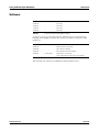
Version History
Manual Version
Software Version
Version date
Changes
1.0
n/a
July 2004
First edition
2.0
n/a
April 2007
New template
Language
Order Number
English
03077063001
e For more information, see:
Software on page G-5
Service Manual on page G-6
Edition notice
91xx pH/Electrolyte Analyzers
Service Manual
This Service Manual is for the maintenance and repair of 91xx pH/Electrolyte
Analyzers (9110 pH Analyzers and 9120, 9130, 9140, 9180 and 9181 Electrolyte
Analyzers).
91xx pH/Electrolyte Analyzers
Every effort has been made to ensure that all the information contained in this
manual is correct at the time of printing. However, Roche Diagnostics GmbH reserves
the right to make any changes necessary without notice as part of ongoing product
development.
Any customer modification to the instrument will render the warranty or service
agreement null and void.
Software updates are done by Roche Service representatives.
9180 Electrolyte Analyzers SN > 12001 are IVD compliant.
Intended use
This manual contains all of the information required for maintenance and repair of
91xx pH/Electrolyte Analyzers (9110 pH Analyzers and 9120, 9130, 9140, 9180 and
9181 Electrolyte Analyzers).
The user must be familiar with the function and operation of the instrument to fully
understand the processes described here.
e For more information about 91xx pH/Electrolyte Analyzers, refer to corresponding
Instructions for Use.
Observe the service and repair procedures described in this manual and use only
genuine Roche replacement parts and Roche-approved materials to guarantee the full
functionality of the 91xx pH/Electrolyte Analyzers.
e For the order numbers of replacement parts, refer to:
91xx pH/Electrolyte Analyzers Spare Part List
Roche Diagnostics
Service Manual · Version 2.0
April 2007
3
91xx pH/Electrolyte Analyzers
e For an overview of possible revisions and available software versions, see:
Software on page G-5
Service Manual on page G-6
Copyrights
© 2007 Roche Diagnostics GmbH, All rights reserved.
The contents of this document may not be reproduced in any form or communicated
to any third party without the prior written consent of Roche Diagnostics. Every
effort is made to ensure its correctness. Subject to change without notice.
Trademarks
COBAS, LIFE NEEDS ANSWERS, ROCHE MICROSAMPLER, SNAPPAK, ISETROL
are trademarks of Roche.
All other trademarks are the property of their respective owners.
Contact addresses
Manufacturer
Roche Diagnostics GmbH
D-68298 Mannheim / Germany
www.roche.com
Roche Diagnostics
4
April 2007
Service Manual · Version 2.0
91xx pH/Electrolyte Analyzers
Contents
Version History
Edition notice
Intended use
Copyrights
Trademarks
Contact addresses
Contents
Preface
How to use this manual
Where to Find Information
Conventions used in this manual
System Description
3
3
3
4
4
4
5
9
9
9
10
Part A
1 Safety information
Important information
Operating safety information
Important notes and warnings
Disinfectants
Deproteinizer
Other disinfectants
ESD protection measures
Explanation of the phenomenon
Influence of electrostatic charges on components
Why is ESD protection so important today?
How can ESD protection be guaranteed?
Conclusion
A-5
A-6
A-6
A-7
A-7
A-7
A-8
A-8
A-8
A-9
A-9
A-9
2 Specifications
Specifications
Specifications
Operating Parameters
Classifications
A-13
A-13
A-13
A-15
3 Interface specifications
Interface specifications
Interface information
Example data string information
Data Link Information (9180/9181 only)
A-19
A-19
A-20
A-20
4 Description of modules
Description of modules
Mechanical assemblies
Fluidic Module
Electronics
Roche Diagnostics
Service manual · Version 2.0
Software operation
Part B
6 Software operation 9110
A-23
A-23
A-27
A-33
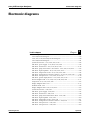
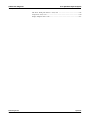
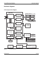
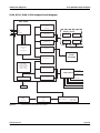
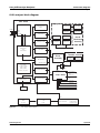
5 Electronic diagrams
Electronic diagrams
9110 analyzer block diagram
9120, 9130, 9140, 9180 analyzer block diagram
9181 analyzer block diagram
System interconnect - 9110, 9120, 9130, 9140 A-42
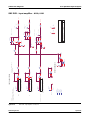
SBC PCB - power supply - 9110, 9120, 9130, 9140
A-43
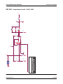
SBC PCB - valve drivers - 9110, 9120, 9130, 9140
A-44
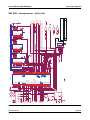
SBC PCB - pump motor driver / door detect - 9110,
9120, 9130, 9140
A-45
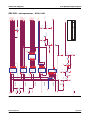
SBC PCB - input amplifiers - 9110, 9120, 9130, 9140
A-46
SBC PCB - temperature circuit - 9110, 9120, 9130,
9140
A-47
SBC PCB - analog selector and A/D converter - 9110,
9120, 9130, 9140
A-48
SBC PCB - microprocessor - 9110, 9120, 9130, 9140
A-49
SBC PCB - printer display drivers - 9110, 9120, 9130,
9140
A-50
Printer daughter PCB - 9110, 9120, 9130, 9140, 9180,
9181
A-51
Lamp PCB - 9110, 9120, 9130, 9140
A-52
Display daughter PCB - 9110
A-53
Preheater PCB - 9110
A-54
Display daughter PCB - 9120, 9130, 9140
A-55
System interconnect - 9180, 9181
A-56
SBC PCB - power supply - 9180, 9181
A-57
SBC PCB - valve drivers - 9180, 9181
A-58
SBC PCB - pump motor driver/door detect - 9180,
9181
A-59
SBC PCB - input amplifier - 9180, 9181
A-60
SBC PCB - temperature circuit - 9180, 9181
A-61
SBC PCB - analog selector and A/D converter - 9180,
9181
A-62
SBC PCB - microprocessor - 9180, 9181
A-63
SBC PCB - microprocessor - 9180, 9181
A-64
SBC PCB - Fluid pack detector - 9180, 9181
A-65
Lamp PCB - 9180, 9181
A-66
Display daughter PCB - 9180
A-67
A-39
A-39
A-40
A-41
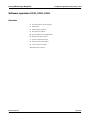
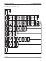
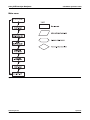
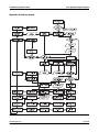
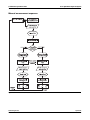
Software operation 9110
Overview
Overall program operation flow
Main menu
Measurement sequence
Print functions menu
QC sample menu
Daily maintenance menu
Operator functions menu
Program instrument menu
B-5
B-5
B-6
B-7
B-8
B-9
B-10
B-11
B-12
B-13
April 2007
5
91xx pH/Electrolyte Analyzers
Service functions menu
Calibration sequence
B-14
B-15
7 Software operation 9120, 9130, 9140
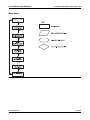
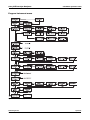
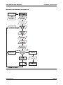
Software operation 9120, 9130, 9140
Overview
Overall program operating flow
Main menu
Measurement sequence
Print functions menu
QC/standard/urine sample menu
Daily maintenance menu
Operator functions menu
Program instrument menu
Service functions menu
Calibration sequence
B-19
B-19
B-20
B-21
B-22
B-23
B-24
B-25
B-26
B-27
B-28
B-29
8 Software operation 9180
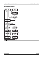
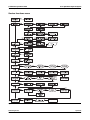
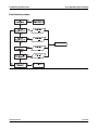
Software operation 9180
Overview
Overall program operation flow
Main menu
Measurement sequence
Print functions menu
QC/standard/dialysate/urine sample menu
Daily maintenance menu
Operator functions menu
Program instrument menu
Service functions menu
Calibration sequence (1) (Example Na/K/Li
calibration)
Calibration sequence (2) (Example Na/K/Li
calibration)
Power-up
B-33
B-33
B-34
B-35
B-36
B-37
B-38
B-39
B-40
B-41
B-42
B-43
B-44
B-45
10 Service functions
Service functions
B-65
TEST ELECTRODES
B-65
TEST SAMPLE SENSOR
B-65
TEST SnapPak SENSOR (9180 and 9181 only) B-65
TEST LANGUAGE SWITCH (9180 and 9181 only)
B-65
TEST SAMPLE DOOR (except 9181)
B-66
TEST PROBE (9181 only)
B-66
TEST AUTOSAMPLER (9181 only)
B-66
TEST PUMP
B-66
TEST PINCH VALVES
B-67
TEST INTERFACE
B-67
TEST AMPLIFIER
B-67
ENTER SERVICE CODE
B-67
Miscellaneous functions
B-69
Maintenance
Part C
11 Adjustments
Adjustments
C-5
Sample contacts adjustment (9110 only)
C-5
Sample sensor adjustment (9120/9130/9140/9180/
9181 only)
C-5
Temperature Adjustment (9110/9140/9180/9181
only)
C-6
12 Maintenance
Maintenance
Daily maintenance
Weekly maintenance
Monthly maintenance
Six month maintenance
Annual preventive maintenance
C-9
C-9
C-9
C-9
C-9
C-9
9 Software operation 9181
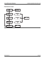
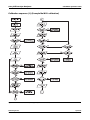
Software operation 9181
Overview
Overall program operting flow
Main menu
Manual measurement sequence
Automated measurement sequence
Print functions menu
QC/std/dialysate/urine sample menu
Daily maintenance menu
Operator functions menu
Program instrument menu
Service functions menu
Calibration sequence (1) (example Na/K/Li
calibration)
Calibration sequence (2) (example Na/K/Li
calibration)
Power-up sequence
Roche Diagnostics
6
B-49
B-49
B-50
B-51
B-52
B-53
B-54
B-55
B-56
B-57
B-58
B-59
B-60
B-61
B-62
Troubleshooting
Part D
13 Troubleshooting
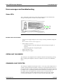
Error messages and troubleshooting
D-5
Status-LEDs
D-5
STATUS: NOT CALIBRATED
D-5
STANDARD A NOT DETECTED
D-5
STANDARD B NOT DETECTED, STANDARD C
NOT DETECTED (9180/9181 only)
D-6
CHECK SAMPLE CONTACTS(9110), CHECK
SAMPLE SENSOR (9120/30/40/80/81)
D-6
CHECK REFERENCE HOUSING
D-7
PLEASE CLOSE SAMPLE DOOR (except 9181) D-7
NO SAMPLE
D-8
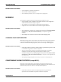
CLEANING FLUID NOT DETECTED
D-8
CONDITIONING FLUID NOT DETECTED (except
9110)
D-8
INTERFACE ERROR
D-9
April 2007
Service manual · Version 2.0
91xx pH/Electrolyte Analyzers
PAPER JAM OR PRINTER DEFECT
D-9
CHECK ELECTRODES
D-9
## NOT CAL’D
D-9
CLOG IN SAMPLE PATH (9110 only), CLOG
CHECK FLUID PATH (except 9110)
D-11
↑↑↑↑ ↓↓↓↓ (Out of range)
D-11
↑ ↓ (Temparature out of range)
D-11
ERR
D-12
PERFORM DAILY MAINTENANCE (except 9110)
D-12
REPLACE FLUID PACK
D-12
CHECK TEMPERATURE (9140/9180/9181 only)
D-12
VALVE OVERTEMP! CHECK VALVES
D-13
ERROR: UPPER NEEDLE SENSOR
D-13
ERROR: LOWER NEEDLE SENSOR
D-13
WHEEL MISSING OR SAMPLER DEFECT
D-13
SAMPLER JAMMED OR DEFECTIVE
D-14
Glossary
Glossary
Index
Part E
E-3
Part F
15 Index
Versions
Part G
16 Versions
Software
Service Manual
Version 1.0
Version 2.0
Roche Diagnostics
Service manual · Version 2.0
G-5
G-6
G-6
G-6
April 2007
7
91xx pH/Electrolyte Analyzers
Roche Diagnostics
8
April 2007
Service manual · Version 2.0
91xx pH/Electrolyte Analyzers
Preface
This manual contains all of the information required for the maintenance and repair
of the 91xx pH/Electrolyte Analyzers.
The user must be familiar with the function and operation of the instrument to fully
understand the processes described here.
e For more information about instructions, refer to:
9180 Electrolyte Analyzers Instructions for Use
Observe the service and repair procedures described in this manual and use only
genuine Roche replacement parts and Roche-approved materials to guarantee the full
functionality of the 91xx pH/Electrolyte Analyzers.
e For the order numbers of replacement parts, refer to:
91xx pH/Electrolyte Analyzers Spare Part List
e For an overview of possible revisions and available software versions, see:
Software on page G-5
Service Manual on page G-6
How to use this manual
o
Keep this Service manual in a safe place to ensure that it is not damaged and remains available
for use.
o
This Service manual should be easily accessible at all times.
To help finding information quickly, there is a table of contents at the beginning of
the book and each chapter. In addition, a complete index can be found at the end.
Where to Find Information
In addition to the Service manual, the following documents are also provided to assist
in finding desired information quickly:
Roche Diagnostics
Service manual · Version 2.0
o
91xx pH/Electrolyte Analyzers Instructions for Use
o
9180 Electrolyte Analyzer Short Instruction
o
91xx pH/Electrolyte Analyzers Service manual (PDF or iSDoc version in
GRIPS)
o
91xx pH/Electrolyte Analyzers Spare Part List (PDF or iSDoc version in
GRIPS)
April 2007
9
91xx pH/Electrolyte Analyzers
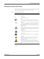
Conventions used in this manual
Visual cues are used to help locate and interpret information in this manual quickly.
This section explains formatting conventions used in this manual.
Symbols
The following symbols are used:
Symbol
Used for
a
Start of procedure
o
List item
e
Cross-reference
h
Call-up (software reference)
Note
All sections or text locations marked with "NOTE" describe safe
procedures that are intended to provide the user with additional help.
Caution
All sections or text passages that are marked with this symbol describe
procedures or indicate conditions or dangers that could damage or
lead to malfunctions in the instrument, and which therefore should
never be attempted.
Warning
Sections marked with this symbol contain information that must be
observed for the prevention of personal injury (to patients, users or
third parties).
Risk of infection!
(according to the standard DIN EN 61010-2-101:2002) (Instrument)
Risk of infection!
(according to the standard DIN ISO 15223-1:2005) (Consumables)
High Voltage
Passages that are marked with this symbol warn of an immediate
danger in connection with electrical wiring or components.
ESD protection measures
All sections or passages that are marked with this symbol warn of
specific dangers in connection with static discharge. Packages that are
marked with this symbol must only be opened by trained technical
staff.
For more information about ESD protection measures, see ESD protection measures
on page A-8.
Roche Diagnostics
10
April 2007
Service manual · Version 2.0
91xx pH/Electrolyte Analyzers
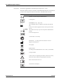
IVD symbols
Instruments: applicable for 9180 Electrolyte Analyzers SN > 12001.
The IVD symbols are used in accordance with DIN EN 980:2003, ISO 15223:2000 (as
per the In Vitro Diagnostics Directive 98/79/EC), and DIN EN ISO 780:1997.
Symbol
Description
This product complies with the requirements in the directive
98/79/EC on in vitro diagnostic medical devices.
Lot designation
Consumables: use by... (expiry date)
The consumables must be completely consumed by the indicated
date.
If a day is not indicated, apply the last day of the respective month.
Store at ...
The conditions necessary to preserve the product's shelf life before
opening.
For in vitro diagnostic use
"Grüner Punkt" (in Germany)
Manufacturer — according to directive 98/79/EC on in vitro
diagnostic medical devices
Store upright
Risk of infection!
(according to the standard DIN ISO 15223-1:2005) (Consumables)
Catalogue number
Caution (refer to accompanying documents). Please refer to safetyrelated notes in the manual, accompanying this instrument.
Please consult instructions for use
Serial number (model plate)
Roche Diagnostics
Service manual · Version 2.0
April 2007
11
91xx pH/Electrolyte Analyzers
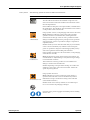
Other symbols
The following symbols are listed as additional information:
Symbol
Description
Electrodes:
This date indicates the limit of the maximum storage time of an
electrode. The electrode must be installed in the instrument no later
than the imprinted date.
If the installation takes place on the imprinted date, it still falls within
the specifications. The calculation of the “Install before” date is based
on the production date of the elctrode.
Danger symbol: T: Toxic (on the packaging of the reference electrode)
T: R23/33/50-53
Rating: Inhalation, swallowing or skin contact with even small
quantities can lead to serious health risks, including fatal risks.
Characteristics of this type of item are severe, possible irreversible
damage to health through repeated or prolonged contact, particular
with carcinogenic, genetic or reproductive (danger to reproductive
capabilities) effects.
Caution: Avoid any contact with the human body. If you feel unwell,
contact a doctor immediately. Any substances with carcinogenic,
genetic or reproductive dangers are indicated appropriately. Always
observe the regulations when handling such substances.
Danger symbol: N: Dangerous to the environment (on the packaging
of the reference electrode)
N: S45/60/61/7
Rating: If released into aquatic and non aquatic environments, can
cause immediate or delayed damage to ecosystems through a change
in environmental conditions.
These substances or their by-products can cause simultaneous
damage to sensitive environmental areas.
Caution: Depending on the potential for damage, do not allow the
substance to enter sewers, soils or the environment. Observe the
specific disposal regulations.
Danger symbol: Xi: Irritant
XI: R36/37/38, S 26-37
Rating: Although not corrosive, momentary, longer-lasting, or
repeated contact with skin or mucous membrane may result in
inflammation. Danger of sensitization during contact with skin
(when classified with R 43).
Caution: Avoid contact with eyes and skin, do not inhale vapors.
Do not use content if the packaging is damaged
Protective gloves, protective goggles and suitable protective clothing
must be worn
Roche Diagnostics
12
April 2007
Service manual · Version 2.0
91xx pH/Electrolyte Analyzers
Abbreviations
The following abbreviations are used:
Abbreviation
Definition
A
ADC
Analogue to digital converter
ANSI
American National Standards Institute
C
CMOS
Complementary Metal-Oxide Semiconductor
E
EEPROM
Electrically erasable programmable read-only memory
e.g.
exempli gratia – for example
EC
European community
EN
European standard
ESD
Electrostatic Discharge
H
HIV
Human Immunodeficiency Virus
HW
Hardware
I
IEC
International Electrical Commission
ISE
Ion selective electrode
IVD
In vitro Diagnostics
L
LCD
Liquid Cristal Display
LED
Light Emitting Diode
M
MC
Measuring chamber
MOS
Metal-Oxide Semiconductor
MSDS
Material safety data sheet
P
PCB
Printed Circuit Board
Q
QC
Quality control
R
REF
Reference solution
S
SBC board
Mainboard of the instrument
SW
Software
T
TTL
Roche Diagnostics
Service manual · Version 2.0
Transisitor-Transistor Logic
April 2007
13
91xx pH/Electrolyte Analyzers
Roche Diagnostics
14
April 2007
Service manual · Version 2.0
System Description
A
1
Safety information . . . . . . . . . . . . . . . . . . . . . . . . . . . . . . . . . . . A-3
2
Specifications . . . . . . . . . . . . . . . . . . . . . . . . . . . . . . . . . . . . . . . A-11
3
Interface specifications . . . . . . . . . . . . . . . . . . . . . . . . . . . . . . . . A-17
4
Description of modules . . . . . . . . . . . . . . . . . . . . . . . . . . . . . . . A-21
5
Electronic diagrams . . . . . . . . . . . . . . . . . . . . . . . . . . . . . . . . . . A-37
April 2007
91xx pH/Electrolyte Analyzers
1 Safety information
Table of contents
Safety information
In this chapter
Chapter
1
Important information ............................................................................................... A-5
Operating safety information ..................................................................................... A-6
Important notes and warnings ................................................................................... A-6
Disinfectants ................................................................................................................ A-7
Deproteinizer ......................................................................................................... A-7
Other disinfectants ................................................................................................ A-7
ESD protection measures ............................................................................................ A-8
Explanation of the phenomenon .......................................................................... A-8
Influence of electrostatic charges on components ............................................... A-8
Why is ESD protection so important today? ........................................................ A-8
How can ESD protection be guaranteed? ............................................................. A-9
Conclusion ............................................................................................................. A-9
Roche Diagnostics
Service manual · Version 2.0
April 2007
A-3
1 Safety information
91xx pH/Electrolyte Analyzers
Table of contents
Roche Diagnostics
A-4
April 2007
Service manual · Version 2.0
91xx pH/Electrolyte Analyzers
1 Safety information
Important information
Important information
This Service Manual contains vital warning and safety information.
This instruments are intended to be used only for the specialized purpose described
in the instructions. The most important prerequisites for use, operation, and safety
are explained to ensure smooth operation. No warranty or liability claims will be
covered if the instrument is used in ways other than those described or if the
necessary prerequisites and safety measures are not observed.
The instrument may be operated only by persons whose qualifications enable them to
comply with the safety measures that are necessary during operation of the
instrument.
Suitable protective equipment, like laboratory clothing, protective gloves, protective
goggles and if necessary mouth protectors, must be worn to prevent direct contact
with biological working materials. In addition, a face mask is required if there is a
risk.
Adjustments and maintenance performed with removed covers and connected power
may be attempted only by a qualified technician who is aware of the associated
dangers.
Instrument repairs are to be performed only by the manufacturer or qualified service
personnel.
Only accessories and supplies either delivered by or approved by Roche are to be used
with the instrument. These items are manufactured especially for use with this
instrument and meet the highest quality requirements.
Operation of the instrument with solutions whose composition is not consistent with
that of the original solutions can negatively affect, above all, the long term
measurement accuracy. Deviations in the composition of the solutions can also
decrease the service life of the electrodes.
The quality control requirements must be completed at least once daily for safety
reasons. Because accurate measurement results depend not only on the proper
functioning of the instrument, but also on a number of other factors (such as
preanalytics), the results produced by the instrument should be examined by a
trained expert before subsequent decisions are reached that are based on the
measurement values.
Explanation:
"Caution, refer to accompanying documents“
Roche Diagnostics
Service manual · Version 2.0
April 2007
A-5
1 Safety information
91xx pH/Electrolyte Analyzers
Operating safety information
Operating safety information
The instrument has been constructed and tested according to the following European
Standards:
o
IEC/EN 61010-1:2001
o
IEC/EN 61010-2-101:2002 (valid for 9180 Electrolyte Analyzers SN > 12001 only)
o
IEC/EN 61010-2-081:2002 + A1:2003
It was delivered from the factory in flawless condition with regards to safety features.
In order to preserve this condition and ensure safe operation, the user must respect
the notices and warnings that are contained in this Service Manual
o
This instrument is classified under the protection class I according to
IEC/EN 61010-1.
o
The instrument meets the conditions for overvoltage category II.
o
The instrument meets the conditions for contamination level 2.
o
Do not operate the instrument in an explosive environment or in the vicinity of
explosive anesthetic mixtures containing oxygen or nitrous oxide.
o
If an object or liquid enters the internal areas of the instrument, remove the
instrument from its power supply and allow an expert to check it thoroughly
before using it again.
o
The instrument is suitable for long-term operation indoors.
o
The power cord may be plugged into a grounded socket only. When using an extension cord,
make sure it is properly grounded.
o
Any rupture of the ground lead inside or outside the instrument or a loose ground connection
may result in hazardous operating conditions. Intentional disconnection of the grounding is not
permitted.
o
The instrument is not suitable for operation with a direct current power supply. Use only the
original mains plug delivered with the instrument.
Important notes and warnings
Roche Diagnostics
A-6
o
Never operate the analyzer in the vicinity of volatile or explosive gases
(e.g. anesthetic gases, etc.)!
o
The instrument must be connected to a 2-pin, grounded socket.
o
The power cable and the plug must be undamaged. Damaged power cables and plugs must be
replaced immediately.
o
Before opening the back panel switch off the instrument and disconnect the power cable.
o
Replace damaged fuses with the specified type of fuse.
April 2007
Service manual · Version 2.0
91xx pH/Electrolyte Analyzers
1 Safety information
Disinfectants
o
Service and repair work must be done only as specified in this manual. Unqualified service or
repair work may result in warranty claims not being granted.
o
Use only suitable tools and test instruments for service and repair work.
o
Do not allow fluids to enter the interior of the instrument, because this may damage the
electronics.
o
Use only slightly moistened cloths or cotton sticks to clean the instrument.
Disinfectants
Use only liquid disinfectant such as protein remover (Roche deproteinizer) or an alcohol-based
(about 70%) surface disinfectant.
Do not spray disinfectant directly onto the instrument because this could cause malfunctions in the
electronics.
Do not use any type of bleaching agent. Exception: Roche Deproteinizer.
Do not attempt to clean/decontaminate any part of the instrument before shutting it down and
unplugging it from the power source.
Before plugging in the instrument again and switching it on always wait for 15 minutes to allow the
disinfectant to evaporate.
Deproteinizer
Composition
Hazards identification
First aid measures
Aqueous NaOCl solution with active chlorine (≤ 2%)
Due to the basic and oxidizing character of the reagent ("Deproteinizer") local
irritations after contact with eyes, skin or mucous membranes cannot be excluded.
After inhalation:
breath fresh air, drink large amounts of water
After skin contact:
wash with generous amounts of water, remove contaminated clothing
After eye contact:
rinse eyes with generous amounts of water, contact an eye specialist
After drinking:
drink large amounts of water, avoid vomiting, contact a doctor
Other disinfectants
Use standard alcohol-based (70%) disinfectants to clean the surface of the
instrument. Read the product information first.
Never use standard disinfectant to clean the tubes and tubing paths under any circumstances!
Do not use any type of bleaching agent. Exception: Roche Deproteinizer.
Roche Diagnostics
Service manual · Version 2.0
April 2007
A-7
1 Safety information
91xx pH/Electrolyte Analyzers
ESD protection measures
ESD protection measures
ESD = Electrostatic Sensitive Device
Explanation of the phenomenon
The most frequent cause of electrostatic discharge is friction of various materials such
as plastic, synthetic fiber, hard rubber or paper.
It can also be caused by bending or applying pressure to a material.
Discharges that are dangerous to components occur when "charged" bodies or
components do not have a discharge connection (ground) to discharge the
electrostatic charge.
The discharges normally do not have a high capacity, but there are often voltage
differences in the range of several thousand volts. The discharges are perceived as
small shocks or visible sparks.
Examples:
o
Shoes with rubber soles:
Friction is caused by walking. A person develops an electrical charge different
from the ground. A discharge occurs when an object (e.g. door handle) is
contacted.
o
Synthetic fiber clothing:
Discharge is audible and is visible in darkness.
The dryer the air the greater the risk of electrical discharge caused by friction.
Eectrostatic charges are less likely to build up in humid air, particularly when saturated with water
vapor.
The probability of ESD phenomena is therefore particularly great in a northern hemisphere winter
in centrally heated rooms where the humidity is low.
Influence of electrostatic charges on components
If a person with an electrostatic charge touches a component, a discharge over a
connection of an IC or semiconductor element may occur. The resulting voltages may
damage the component.
Critical situations can occur while repairing or testing components if they are lying
on a more or less conductive surface (e.g. table top) and a person with an electrostatic
charge touches them. A discharge through a critical component connection can also
occur in this case.
Roche Diagnostics
A-8
April 2007
Service manual · Version 2.0
91xx pH/Electrolyte Analyzers
1 Safety information
ESD protection measures
Why is ESD protection so important today?
Formerly, current controlling semiconductors were mostly used (TTL, normal
transistors, etc.).
Today the principle of current logic is virtually the only technology in use in MOS
and CMOS components.
Currents generated by an electrostatic discharge (as much as several kV!) destroy the
sensitive component inputs or cause hidden damage. This damage is generally not
immediately detectable.
Another effect is that the clearances inside the ICs continuously become smaller. The
internal wires become thinner and thinner, the allowable maximum input voltages
become smaller and the effects of any discharges become more and more critical.
How can ESD protection be guaranteed?
A continuous discharge is required when working on an electronic assembly. Do this
as follows:
o
Use ESD wrist bands (special wrist bands connected to a protective ground).
o
Repairs and tests on assemblies must only be conducted on tables with ESD mats
connected to grounds or ESD wrist bands.
o
Always pick up components at the edge (e.g. like a photo).
o
Components must always be transported in ESD packages or appropriate storage
or shipping containers (use original packaging!).
o
Shoes with rubber soles or clothing of synthetic fibers must not be worn in
workshops where electronic components are repaired.
o
Use a humidifier if necessary to maintain optimum humidity in the work area.
o
Do not touch assemblies or components with the hand after testing.
o
Always transport and ship assemblies or components for repair in ESD protective
packaging only. This will prevent further damage that may result in
misinterpretation of the original cause of the fault.
The ESD mat consists of materials that have a very low, defined conductivity (1012 ohms).
The following materials prevent charges caused by friction from building up and protect the
component from damage.
o
ESD mats
o
ESD packages
o
Shipping containers
Conclusion
Of course, not all circuit boards and electronic assemblies require such careful
handling. An electrical board that only carries simple plug connectors does not
require ESD packaging.
In cases of doubt always use ESD packaging.
Roche Diagnostics
Service manual · Version 2.0
April 2007
A-9
1 Safety information
91xx pH/Electrolyte Analyzers
ESD protection measures
Roche Diagnostics
A-10
April 2007
Service manual · Version 2.0
91xx pH/Electrolyte Analyzers
2 Specifications
Table of contents
Specifications
In this chapter
Chapter
2
Specifications ............................................................................................................. A-13
Specifications ....................................................................................................... A-13
9110 ................................................................................................................ A-13
9120/9130/9140/9180/9181 ........................................................................... A-13
Operating Parameters ......................................................................................... A-13
9110 ................................................................................................................ A-13
9120/9130/9140/9180/9181 ........................................................................... A-14
Common operating parameter ..................................................................... A-14
Classifications ...................................................................................................... A-15
Product data ................................................................................................... A-15
Approvals ....................................................................................................... A-15
Roche Diagnostics
Service manual · Version 2.0
April 2007
A-11
2 Specifications
91xx pH/Electrolyte Analyzers
Table of contents
Roche Diagnostics
A-12
April 2007
Service manual · Version 2.0
91xx pH/Electrolyte Analyzers
2 Specifications
Specifications
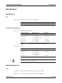
Specifications
Specifications
9110
Sample types
Whole blood, Serum, Plasma, QC solutions
Reported parameters
Measuring range
Resolution
pH
6.00 - 8.00
0.001 pH units
Table A-1
9110 reported parameters
9120/9130/9140/9180/9181
Sample types
Whole blood, Serum, Plasma
Reported parameters
Measuring range
Resolution
Sodium (Na+)
40 - 205 mmol/L
0.1 mmol/L
1.5 - 15 mmol/L
0.01 mmol/L
Potassium (K
+)
(0.8 - 15 mmol/L dialysate)
Chloride (Cl–)
Calcium (Ca
2+)
+)
Lithium (Li
Table A-2
Sample type
50 - 200 mmol/L
0.1 mmol/L
0.2 - 5.0 mmol/L
0.01 mmol/L
0.1 - 6.0 mmol/L
0.001 mmol/L
9120, 9130, 9140, 9180, 9181 reported parameters (1)
Urine
Reported parameters
Measuring range
Resolution
Sodium (Na+)
1 - 300 mmol/L
1.0 mmol/L
4.5 - 120 mmol/L
0.1 mmol/L
Potassium (K
+)
(60 - 120 mmol/L
with add. dilution)
Chloride (Cl–)
Table A-3
1 - 300 mmol/L
1.0 mmol/L
9120, 9130, 9140, 9180, 9181 reported parameters (2)
Calcium and Lithium are not measured in urine samples.
Lithium is not measured in dialysate samples.
Operating Parameters
9110
Sample types
Whole blood, serum, plasma, aqueous and QC solutions
Sample device
Syringe, sample cup, capillary, Roche MICROSAMPLER
Roche Diagnostics
Service manual · Version 2.0
April 2007
A-13
2 Specifications
91xx pH/Electrolyte Analyzers
Specifications
Sample size
Analysis time
Sample rate
pH Sensor
Reference System
Calibration
Warm-up time
25 μL
70 seconds
o
40 per hour with printout
o
50 per hour without printout
pH sensitive flow-through glass capillary electrode in transparent acrylic plastic
Open liquid junction, flow-through electrode
o
Fully automatic
o
1 point with each sample
o
2 point every 3 hours
10 minutes
9120/9130/9140/9180/9181
Sample types
Sample device
Sample size
Analysis time
Sample rate
Sodium (Na+) sensor
Whole blood, serum, plasma, urine, dialysate (acetate or bicarbonate)
Syringe, sample cup, capillary, Roche MICROSAMPLER
95 μL
50 seconds
o
45 per hour with printout
o
60 per hour without printout
Ion-selective, flow-through, glass capillary electrode
Potassium (K+) sensor
Ion-selective, flow-through, liquide membrane electrode
Chloride (Cl–) sensor
Ion-selective, flow-through, liquide membrane electrode
Calcium (Ca2+) sensor
Ion-selective, flow-through, liquide membrane electrode
Lithium (Li+) sensor
Ion-selective, flow-through, liquide membrane electrode
Reference system
Calibration
Warm-up time
Open liquid junction, flow-through electrode
o
Fully automatic
o
1 point with each sample
o
2 point every 3 hours (9180/9181 every 4 hours)
10 minutes
Common operating parameter
Standby mode
Temperature
Roche Diagnostics
A-14
Suspends calibrations
Room temperature, 15 - 32°C, 60 - 90 °F
April 2007
Service manual · Version 2.0
91xx pH/Electrolyte Analyzers
2 Specifications
Specifications
Humidity
Data management
Diganostic programs
Electronics
maximum 85 % relative humidity, non-condensing
Quality control memory storage, 3 levels, 35 values; calculation of mean, standard
deviation and coefficien of variation (CV)
user-controlled diagnostics, YES/NO operation via the display
Microprocessor-controlled
Display
LCD dot-matrix, 2 lines, 16 characters per line
Printer
Integral thermal printer, 16 characters width
Autosampler (9181 only)
Interface
DataLink
Electrical requirements
Nominal power consumption
Dimensions
Integral turntable, 18 positions, 2 mL or 0.25 mL sample cups
RS232C serial port
Data link to COMAPCT 2/3 (9180/9181)
100 - 240 VAC, 50/60 Hz (90 - 250 VAC for 9110), self adjusting
50 W
Height
335 mm (12.2")
Width
315 mm (12.4")
Depth
295 mm (12.0")
Weight
approx. 6 kg (13 lbs)
Table A-4
Instrument dimensions
Classifications
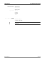
Product data
Safety category
Device type
I
B (according to ÖVE-MG/EN 60601-1,
IEC 601-1)
Mode of operation
Protection classification
Explosion protection
continuous operation
IP 20
the device is not designed for operation in explosive environments.
Approvals
CSA, CE, FCC Class B
CLIA Complexity Category: Moderate
Test System Code: 04739
Roche Diagnostics
Service manual · Version 2.0
April 2007
A-15
2 Specifications
91xx pH/Electrolyte Analyzers
Specifications
FDA 510(k) numbers:
K932642 (9110)
K961458 (9180)
K972673 (9181)
Analyte Codes:
Na+: 5805
K+: 4910
Cl–: 1018
Ca2+: 1004
Li+: 3712
Special requirements for IVD
products
EN 61010-2: 2001-12
EN 61010-2: 2002-01
(9180 SN > 12001 only)
Data subject to change without notice. Technical information is supplied for general informational
purposes only!
Roche Diagnostics
A-16
April 2007
Service manual · Version 2.0
91xx pH/Electrolyte Analyzers
3 Interface specifications
Table of contents
Interface specifications
In this chapter
Chapter
3
Interface specifications .............................................................................................. A-19
Interface information .......................................................................................... A-19
Software ......................................................................................................... A-19
Example data string information ....................................................................... A-20
Automatic Calibration Report ...................................................................... A-20
Serum sample report ..................................................................................... A-20
Data Link Information (9180/9181 only) .......................................................... A-20
Roche Diagnostics
Service manual · Version 2.0
April 2007
A-17
3 Interface specifications
91xx pH/Electrolyte Analyzers
Table of contents
Roche Diagnostics
A-18
April 2007
Service manual · Version 2.0
91xx pH/Electrolyte Analyzers
3 Interface specifications
Interface specifications
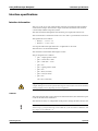
Interface specifications
Interface information
The 9110, 9120, 9130, 9140, 9180 and 9181 analyzers are equipped with a standard
serial interface output. This interface output is intended to be used with standard
commercially available computer systems.
The data transmitted through the serial interface port employs the ASCII code.
The serial interface is terminated on the rear cover with a 9-pin male DB-9 connector.
The signal levels are as follows:
o
Binary 1 = -12 V to -3 V
o
Binary 0 = +3 V to +12 V
Two stop bits follow the eight data bits to complete the 10 bit word.
The baud rate is set at 9600 Baud fixed.
The maximal recommended cable length is 40 feet.
The pin assignment is as follows:
o
pin 1...sample ground...GND
o
pin 2...receive data....RxD
o
pin 3...send data.......TxD
o
pin 4...NC
o
pin 5...signal ground...GND
o
pin 6...NC
o
pin 7...RTS (not used)
o
pin 8...CTS(not used)
o
pin 9...NC
(NC=Not Connected)
Higher discharge current
A higher discharge current can be expected when using the serial interface. This must be checked by
suitably qualified personnel, depending on the local regulations.
Software
The patient sample data is sent at the end of each measurement, the calibration report
is sent at the end of each calibration.
The interface is always on, independent of the printer settings; the data is always sent.
Note
The arrow up (e.g. out of normal range) is sent as HEX 18 (↑), the arrow down as HEX19 (↓) and
the ° (degree) is sent as HEX1A (→).
Roche Diagnostics
Service manual · Version 2.0
April 2007
A-19
3 Interface specifications
91xx pH/Electrolyte Analyzers
Interface specifications
Example data string information
Automatic Calibration Report
<sx>* AVL 9130*<cr><crlf>ELECTROLYTE ISE<cr><crlf> 03JAN92
10:51crcrlf*CALIBR REPORT*<cr><crlf><cr><crlf>
DailyMaintenance<cr><crlf>Performed Last: <cr><crlf> 02JAN92 10:35
<cr><crlf><cr><crlf> Standard A<cr><crlf>Na = -112mV (3)<cr><crlf>
K = -1392mV (3)<cr><crlf>Cl = -106mV (3)<cr><crlf><cr><crlf>
Difference A-B<cr><crlf>Na = 1402mV ( )<cr><crlf>K = 1032mV ( )
<cr><crlf>Cl = -1006mV ( ) <cr><crlf><cr><crlf>Fluid Pack:<cr><crlf>
68% Remaining<cr><crlf><cr><crlf><ex>
Serum sample report
<sx>* AVL 9130*<cr><crlf>ELECTROLYTE ISE<cr><crlf> 03JAN92
10:59<cr><crlf><cr><crlf> Name: ..........<cr><crlf> ..........
<cr><crlf>Sample: SERUM<cr><crlf><cr><crlf> Sample No.13
<cr><crlf><cr><crlf>Na= 159soh mmol/L<cr><crlf>K = 5.4 mmol/L
<cr><crlf>Cl= 122soh mmol/L<cr><crlf><cr><crlf>*PERFORM DAILY *
<cr><crlf>*MAINTENANCE ! *<cr><crlf><cr><crlf><ex>
Data Link Information (9180/9181 only)
The data link with the COMPACT 2/3 blood gas analyzer allows to combine ISE
results with pH/blood gas results on one printout. If Ca2+ is activated on the 9180/
9181, a pH-corrected Ca2+ value will be calculated and printed on the combined
sample report.
For connection of the 9180/9181 analyzer to the COMPACT 2/3 analyzer, the optional
Interface Kit is required. To install the kit, first turn both instruments off. Connect the
interface filter provided in the kit to the RS232 port on the 9180/9181. Then connect
one end of the cable to the interface filter, the other end to the COM 2 port on the
COMPACT 2/3. On the COMPACT 2/3, select 9180 under the COM 2 interface
options.
e See COMPACT 2/3 Operator's Manual for details.
Roche Diagnostics
A-20
April 2007
Service manual · Version 2.0
91xx pH/Electrolyte Analyzers
4 Description of modules
Table of contents
Description of modules
Insert introducing text here.
In this chapter
Chapter
4
Description of modules ............................................................................................ A-23
Mechanical assemblies ........................................................................................ A-23
Front door assembly ...................................................................................... A-23
Needle unit assembly ..................................................................................... A-23
Electrode holder assembly ............................................................................ A-24
Peristaltic pump assembly ............................................................................. A-24
Solenoid assembly ......................................................................................... A-25
Printer assembly ............................................................................................ A-25
Rear panel assembly ...................................................................................... A-25
SBC board ...................................................................................................... A-26
Lamp board .................................................................................................... A-27
Display board ................................................................................................. A-27
Fluidic Module .................................................................................................... A-27
Standard A .................................................................................................... A-27
Standard B ..................................................................................................... A-27
Standard C (not on 9110) ............................................................................. A-27
Cleaning solution (9110 only) ...................................................................... A-28
Reference solution ......................................................................................... A-28
Waste liquids .................................................................................................. A-28
Main tube set (all models)/ Intake tube set (9110 only) ............................. A-28
Sample Contacts (9110 only) ........................................................................ A-29
Electronics ............................................................................................................ A-33
ISE SBC card .................................................................................................. A-33
Lamp board .................................................................................................... A-34
Display board ................................................................................................. A-35
Roche Diagnostics
Service manual · Version 2.0
April 2007
A-21
4 Description of modules
91xx pH/Electrolyte Analyzers
Table of contents
Roche Diagnostics
A-22
April 2007
Service manual · Version 2.0
91xx pH/Electrolyte Analyzers
4 Description of modules
Description of modules
Description of modules
After changing any part of the analyzer always perform a calibration of the analyzer as well as a full
QC measurement. QC measurements must be performed in their entirety (i.e., all three QC levels
must be measured). Omitting QC measurements or ignoring QC measurement results may lead to
incorrect patient measurements, which may result in incorrect clinical decisions, possibly
endangering the patient's health.
Mechanical assemblies
Front door assembly
For the 9110, 20, 30, 40 and 80 analyzers, the front door can be removed by moving
the analyzer to the edge of a work surface so the analyzer door, when opened, will
extend past the edge of the work surface. With one hand, hold the analyzer door near
the right side hinge pin and, with the other hand, gently apply pressure to the middle
rear area of the door. This will allow the right hinge pin to clear the retaining hole in
the main chassis. The door can then be removed from the analyzer.
The 9181 front panel can be removed by tilting it slightly away from the analyzer and
lifting it straight up. The plastic window can also be replaced in the field by gently
pressing from the rear of the window and snapping the plastic window out toward the
front of the analyzer door. The door magnets cannot be replaced in the field as they
are glued in place with conductive adhesive.
Due to the update of the 9180 Electrolyte Analyzer according to IVDD compliance a new shielded
front door "FRONT DOOR 9180" is available and compatible with any 9180 Electrolyte Analyzer
(old type SN < 11999 and new type SN > 12001) and with 9120, 30, 40 Electrolyte Analyzers.
Further information: see the 91xx Spare Parts List.
e See the 91xx Spare Parts List for a detailed reference of the parts of this assembly.
Needle unit assembly
To remove the 9110 fill port for replacement or cleaning, grasp the white tab on the
fill port and rotate the bayonet-style connector counter-clockwise. Gently pull the fill
port forward to remove. Replacement can be accomplished in the reverse order.
During removal, be careful not to bend the needle.
The 9110 fill port assembly is desinged for easy removal without the use of tools, for
cleaning, changing tubing or replacement. First, disconnect the sample intake tube on
the left side of the fill port assembly from the sample preheater. Grasp the fill port
assembly and pull it forward carefully. Disconnect the wire from the needle arm. To
reassemble, reconnect the wire, press the fill port assembly into place and reconnect
the tubing.
The 9110 wash port located on the underside of the flap can be removed by appying
pressure to one side to overcome the snap fit. To reinsert, align wash port and apply
pressure to snap into place.
The 9120, 30, 40, 80 and 81 sample needle and fill port are both designed for easy
replacement by the user. To remove the fill port assembly for replacement, pull the fill
Roche Diagnostics
Service manual · Version 2.0
April 2007
A-23
4 Description of modules
91xx pH/Electrolyte Analyzers
Description of modules
port holder towards the front for easy access. Then, press the two plastic tabs on the
fill port to allow removal of the fill port from the fill port holder. The sample needle
can also be removed and is supplied as a one-piece assembly including the intake
tubing.
To remove the 9120, 30, 40, 80 and 81 sample needle, grasp the needle near the white
holder block and pull up to unsnap the sample needle from its position. To replace
the assembly, align a replacement sample needle and press the replacement assembly
into place.
Two (9110) or three screws (9120, 30, 40, 80, 81) located on the left side of the
assembly hold the needle unit assembly in place. To access the two rear screws, turn
power off and remove the rear panel. The rear panel can be moved away from the unit
for easier access by unplugging the wire harness from the power supply. The SBC
board can now be removed by removing the screws which secure the SBC board and
disconnecting the cables on the SBC board.
Disconnect the connector to the lamp board which supplies the Door Open signal.
The two rear screws which secure the needle unit can now be removed using a Philips
screwdriver (9110) or an Allen wrench (9120, 30, 40, 80, 81). Then, remove the front
securing screw (n./a. on the 9110), the sample intake tubing and the reagent supply
tubing (red tag) from the fill port. The needle unit can now be removed from the
front of the analyzer for replacement.
e See the 91xx Spare Parts List for a detailed reference of the parts of the needle unit.
Electrode holder assembly
To remove the electrode holder assembly from the analyzer, first unplug the sample
intake tubing on the right side of the module, then the preheater cable (9110 only) or
the sample sensor cable (9120, 30, 40, 80 and 81), then remove the reference solution
tubing connector and last, take out the waste tube (green tag) at the left side of the
electrode holder. The electrode holder can now be removed by pressing the two
plastic tabs (right and left side of the module) and sliding the module forward. Press
the plastic tabs again to release the second detent and completely remove the module
from the analyzer. The sample preheater or the sample sensor and/or the left side
electrode holder can be removed and replaced by removing the screws on the under
side of this module.
e See the 91xx Spare Parts List for a detailed reference of the parts of this assembly.
Peristaltic pump assembly
Replacement of the roller assembly of the peristaltic pump can be accomplished by
removing the pump tubing and firmly pulling the roller assembly toward the front. To
replace the roller assembly, align the roller and the flat on the motor shaft and press
the replacement roller into position.
To remove the motor, first remove the rear panel assembly and SBC Board.
e For details, see Rear panel assembly on page A-25, SBC board on page A-26.
Now, the electrical connector on the lamp board can be accessed to unplug the motor
connector. The motor can now be removed by removing four screws located on the
front of the housing near the peristaltic pump.
Roche Diagnostics
A-24
April 2007
Service manual · Version 2.0
91xx pH/Electrolyte Analyzers
4 Description of modules
Description of modules
Solenoid assembly
Removal of each solenoid is identical. Each solenoid valve has a removable pressure
piece which is held in place by a solenoid cap. To remove the pressure piece, locate the
arrow on the solenoid cap and remove the solenoid cap by sliding it off the solenoid
shaft in the direction of the arrow. This exposes the pressure piece which can now be
removed from the solenoid shaft. To replace pressure piece and cap, energize the
solenoid as described in TEST PINCH VALVES on page B-67. This extends the
solenoid shaft to the outermost position for ease in replacing pressure piece and cap.
Removal of the pressure piece and cap is required prior to removing the solenoid and
allows for easier replacement of the tubing under each solenoid.
To remove the solenoid assembly, the rear panel and the SBC Board (described in
Rear panel assembly on page A-25 and SBC board on page A-26) must be removed
first.
e For details, see Rear panel assembly on page A-25, SBC board on page A-26.
Each solenoid has an electrical connection to the lamp board which must be
unplugged prior to removal of the solenoid. At this point, remove the two screws on
the front panel to remove the solenoid assembly.
Note
The 9110 R-solenoid incorporates two heat sinks and is not interchangeable with the other
solenoids.
Printer assembly
The printer assembly is designed to allow for easy removal by the user which can be
accomplished without removal of the electrical power to the analyzer. Slide the paper
tray forward to allow access to the printer, tear the paper roll and completely remove
it together with the paper tray. Slide fingers under the printer assembly and pull the
printer forward. This will disengage the printer from the interconnector and enable
removal of the assembly from the front of the analyzer. Removal of the printer should
be performed for replacement and for removal of a paper jam.
To replace the printer, locate the printer slide and insert the printer assembly. Press
firmly into place to ensure electrical connection of the printer.
Note
Never attempt to dislodge paper from the printer with a paper clip or similar object to avoid
damage to the print head or printer platen.
Due to the update of the 9180 Electrolyte Analyzer according to IVDD compliance a new printer
assembly "PRINTER MODULE, ISE" is available and compatible with 9110 pH Analyzers and
with any 9120, 30, 40, 80 and 81 Electrolyte Analyzer.
e Further information: see the 91xx Spare Parts List.
Rear panel assembly
To remove the rear panel assembly, ensure that the power cord has been disconnected
from the analyzer. Remove the four corner screws to expose the rear panel. The power
supply module located on the rear panel assembly can now be removed by removing
the three screws securing the circuit board and by disconnecting the wiring
Roche Diagnostics
Service manual · Version 2.0
April 2007
A-25
4 Description of modules
91xx pH/Electrolyte Analyzers
Description of modules
interconnections. The main power receptacle can also be replaced by removing the
two screws holding this assembly.
Due to the update of the 9180 Electrolyte Analyzer according to IVDD compliance a new power
supply module "POWER SUPPLY 9180 >SN 12001" is available and compatible with 9180
Electrolyte Analyzers serial number > 12001 only.
The former power supply "MODULE POWER SUPPLY, ISE" is still available and has to be used
for 9180 Electrolyte Analyzers SN < 11999, for 9110 pH Analyzers and for 9120, 30, 40 and 81
Electrolyte Analyzers.
e Further information: see the 91xx Spare Parts List.
After changing the main board or the power supply always perform a measurement of protective
ground resistance to ensure a safe connection of the system ground. Always measure with the power
cord attached to the analyzer. The resistance measurement has to be done between the ground pin
of the power plug and several ground connectors placed on each of the analyzer's electronic
components such as power supply or main board and shielding. The total resistance should not
exceed 0.5 ohms. Be sure to consider the resistance of the ohmmeter's connecting cables.
SBC board
After the rear panel has been removed, the SBC Board is accessible for removal. This
circuit board can be removed by removing the seven screws securing the board to the
housing and by disconnecting electrical connectors from the power supply module,
display board and lamp board.
e For details, see Rear panel assembly on page A-25.
The electrode push pins can now be replaced by simply pulling the connecting pin
from its socket. When installing the board, make sure to place the plastic washers
under the screw heads.
Due to the update of the 9180 Electrolyte Analyzer according to IVDD compliance a new SBC
board "MAINBOARD 9180 >SN 12001" is available and compatible with 9180 Electrolyte
Analyzers serial number > 12001 only. The former SBC board "MAINBOARD 9180 <SN 11999"
is still available and has to be used for 9180 Electrolyte Analyzers SN < 11999.
Further information: see the 91xx Spare Parts List.
After changing the main board or the power supply always perform a measurement of protective
ground resistance to ensure a safe connection of the system ground. Always measure with the power
cord attached to the analyzer. The resistance measurement has to be done between the ground pin
of the power plug and several ground connectors placed on each of the analyzer's electronic
components such as power supply or main board and shielding. The total resistance should not
exceed 0.5 ohms. Be sure to consider the resistance of the ohmmeter's connecting cables.
Note
Due to the update of the 9180 Electrolyte Analyzer according to IVDD compliance the printouts,
display messages and data links sequences of the 9180 Electrolyte Analyzers serial number > 12001
will show "Roche" instead of "AVL". This also applies to 9180 Electrolyte Analyzers serial number
< 11999 in case of replacing the main board "MAINBOARD 9180 >SN 12001" or the program set
"PROGRAM SET 9180".
Roche Diagnostics
A-26
April 2007
Service manual · Version 2.0
91xx pH/Electrolyte Analyzers
4 Description of modules
Description of modules
Lamp board
The rear panel and SBC board must be removed to gain access to the lamp board.
Remove one screw and washer which hold the board in place and remove the
electrical connectors to remove this board.
Display board
The rear panel and SBC board must be removed to gain access to the display board.
Remove three screws and 50 degree spacers and unplug the preheater or sample
sensor cable from the front and the ribbon cable to the SBC board to remove the
display board.
Fluidic Module
Standard A
Standard A is drawn to the electrode module by vacuum provided by the peristaltic
pump.
9110 pH Analyzers:
When Standard A is to be aspirated into the electrode module, solenoid valve A and R
are opened. Standard A is then drawn from the ISE SnapPakTM until Sample Contact
1 detects Standard A bridging the T-piece and Sample Contact 1. At this point,
solenoid valve V is opened and solenoid valve A is closed. The standard is pumped up
the tubing, through the wash portand into the sample needle until Sample Contact 2
detects the standard. The peristaltic pump slows down and the standard moves into
the electrode module until detected by Sample Contact 3 (bridge between sample
preheater tube and reference electrode). Then, the pump stops.
9120, 30, 40, 80, 81 Electrolyte
Analyzers:
When Standard A is to be aspirated into the electrode module, solenoid valve A is
opened and solenoid valves B, V and R are closed. Standard A is then drawn from the
ISE SnapPakTM, to the fill port, through the sample needle and is sensed by the
sample sensor. At this point, solenoid valve V is opened and solenoid valve A is closed
as the peristaltic pump continues to pump Standard A into the electrode module. As
the trailing edge of the Standard A sample is sensed by the sample sensor, the
peristaltic pump stops.
During the time Standard A is aspirated into the electrode module, the reference
housing is pressurized due to the peristaltic pump providing pressure to the reference
solution line and solenoid valve R being closed. An amount of reference solution is
forced out through the reference junction to provide contact to the sample.
Standard B
The process for Standard B is identical to that of Standard A with the exception of the
operation of solenoid valve B. This solenoid valve is operated in reverse order of
Standard A aspiration.
Standard C (not on 9110)
The process for Standard C is identical to that of Standard A with the exception of the
operation of solenoid valve C. This solenoid valve is operated in reverse order of
Standard A aspiration.
Roche Diagnostics
Service manual · Version 2.0
April 2007
A-27
4 Description of modules
91xx pH/Electrolyte Analyzers
Description of modules
Cleaning solution (9110 only)
The cleaning routine within the 9110 pH Analyzer is automatic with cleaning solution
being aspirated through the system every 40th sample or every 24 hours. Automatic
operator-initiated cleaning can also be performed, by selecting ELECTRODE
CLEANING from the main menu. The cleaning routine is very similar to the
aspiration of Standard A or B with solenoid valve C being opened to allow cleaning
solution to be aspirated through the fluidic path. The timing of the cleaning solution
routine allows for a larger volume of cleaning solution to be aspirated than the
Standard A or B cycles to ensure that cleaning solution covers the electrodes, wash
port, fill port, sample needle and preheater during the cleaning cycle.
Reference solution
The reference housing is filled automatically using the second winding of the
peristaltic pump and solenoid valve R. The reference solution connector allows for
the reference housing tubing to be plugged into the reference solution circuit. As the
peristaltic pump aspirates reference solution, solenoid valve R is opened to allow
excess solution to be pumped into the reference return line of the ISE SnapPakTM.
A check valve is placed in the return line to ensure that the KCl output is constant
(9110 only).
Waste liquids
Calibration standard and sample waste are pumped out of the left side of the
electrode module (green-banded tubing) through the peristaltic pump to the waste
line of the ISE SnapPakTM. An internal one-way valve is incorporated into the waste
line of each ISE SnapPakTM to prevent any waste products from leaking out of the ISE
SnapPakTM.
Main tube set (all models)/ Intake tube set (9110 only)
The main tube set is supplied as a pre-cut tubing harness with the fluidic
interconnections preassembled. Replacement of the tube set should be performed
annually. For removal of the tubing, first remove the ISE SnapPakTM from the reagent
compartment. This will allow access for removal of the white TPR block which is the
main interconnection between the ISE SnapPakTM and the tubing. This block can be
removed by grasping the front surface and pulling forward. Next, remove tubing from
each solenoid valve. Follow the procedure outlined in Section 4.1.5 for disassembly of
the solenoid valves to enable fluidic tubing to be easily removed at each solenoid.
e For details, see Rear panel assembly on page A-25, SBC board on page A-26.
Pull the two pump windings at the peristaltic pump tube set off the pump roller and
remove the white reference solution tube connector. Remove the white TPR reference
solution block by grasping the front of the block and pulling forward. The three tube
connections are labeled with green, blue and red tags. All remaining tubes can now be
removed and the entire tubing harness can be discarded.
Fit the replacement tubing harness and assemble in reverse order as disassembly.
Reference the Tube Diagram on the next page for correct tube locations.
Intake Tube Set (9110 only)
Roche Diagnostics
A-28
The intake tube set comprises three pieces of tubing. A short piece (red tag) fits
between the white T-piece and the standard contact. The long piece can be positioned
between the standard contact and the wash port. The remaining tube can be fitted
between the sample needle and the preheater tube.
April 2007
Service manual · Version 2.0
91xx pH/Electrolyte Analyzers
4 Description of modules
Description of modules
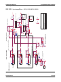
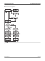
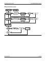
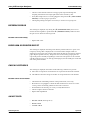
Sample Contacts (9110 only)
The 9110 fluid detection is based on the principle of measuring the impedance in a
sample contact path. There are three sample contacts in the 9110 pH Analyzer.
Sample Contact 1 senses standard solution draws.
Roche Diagnostics
Service manual · Version 2.0
April 2007
A-29
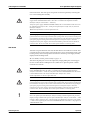
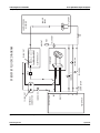
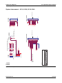
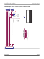
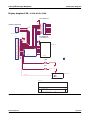
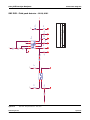
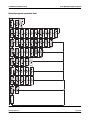
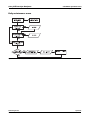
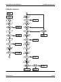
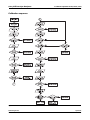
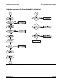
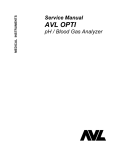
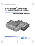
Figure A-1
Roche Diagnostics
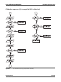
A-30
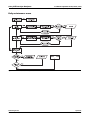
FLUID PACK
A
B
CLEANING
WASTE
REF
REF. RETURN
CHECK VALVE
SOLENOID R
REFERENCE
CONNECTOR
YELLOW DOT
FLUID
CONNECTOR
SOLENOID A
GREEN
REF
pH
PRE
HEATER
YELLOW DOT
SOLENOID B
SOLENOID C
PERI PUMP
ELECTRODE ASSY
9110 FLUIDIC DIAGRAM
RED
SOLENOID V
BLUE
AIR VENT
FILLPORT
SAMPLE
PROBE
SAMPLE PROBE
ASSEMBLY
4 Description of modules
91xx pH/Electrolyte Analyzers
Description of modules
9110 fluidic diagram
Service manual · Version 2.0
April 2007
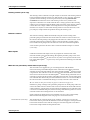
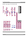
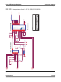
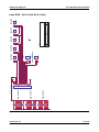
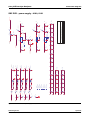
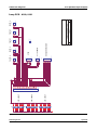
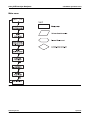
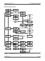
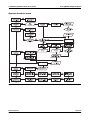
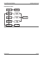
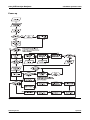
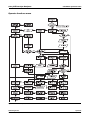
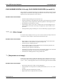
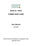
Figure A-2
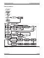
Roche Diagnostics
Service manual · Version 2.0
FLUID PACK
NOT USED C
A
B
WASTE
REF
REF. RETURN
SOLENOID R
REFERENCE
CONNECTOR
YELLOW DOT
FLUID
CONNECTOR
SOLENOID A
GREEN
Na
K
Cl
Ca
SOLENOID B
PERI PUMP
ELECTRODE ASSY
REF
YELLOW DOT
9120, 9130, 9140 FLUIDIC DIAGRAM
RED
SOLENOID V
BLUE
AIR VENT
FILLPORT
SAMPLE
PROBE
SAMPLE PROBE
ASSEMBLY
91xx pH/Electrolyte Analyzers
4 Description of modules
Description of modules
9120, 9130, 9140 fluidic diagram
April 2007
A-31
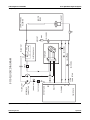
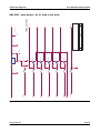
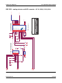
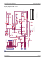
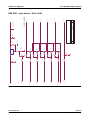
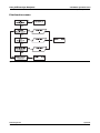
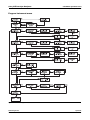
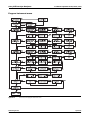
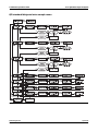
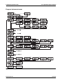
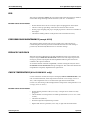
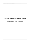
Figure A-3
Roche Diagnostics
A-32
FLUID PACK
A
B
C
WASTE
REF
REF. RETURN
SOLENOID R
REFERENCE
CONNECTOR
YELLOW DOT
FLUID
CONNECTOR
SOLENOID A
SOLENOID C
GREEN
Na
K
Li
Cl
Ca
SOLENOID B
PERI PUMP
ELECTRODE ASSY
REF
YELLOW DOT
RED
SOLENOID V
BLUE
AIR VENT
9180/9181 FLUIDIC DIAGRAM
FILLPORT
SAMPLE
PROBE
SAMPLE PROBE
ASSEMBLY
4 Description of modules
91xx pH/Electrolyte Analyzers
Description of modules
9180, 9181 fluidic diagram
Service manual · Version 2.0
April 2007
91xx pH/Electrolyte Analyzers
4 Description of modules
Description of modules
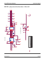
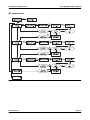
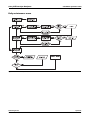
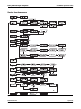
Electronics
ISE SBC card
Power circuits
Power is supplied to this circuit board through connector JP3 from the power supply
assembly. Test points are provided to measure supply voltages, and light emitting
diodes D1 through D5 are turned on to indicate each supply voltage present on the
card. Since each LED is connected in series after the fuse, a blown fuse results in the
respective LED turned off.
Four additional voltage regulator circuits are mounted on the ISE SBC II Card.
IC U2 and IC U3 provide -8 VDC and +8 VDC (9180/9181: -5 VDC and
+5 VDC) and are used to provide the supply voltages for the analog circuitry. IC U1
develops the supply voltage used to operate the peristaltic pump and provide either
+10 VDC or +22 VDC. The +22 VDC is supplied only for the FAST speed and
+10 VDC is used for all other pump speeds. Signal FAST/SLOW determines which
supply voltage is selected.
U5 switches the voltage between 22 VDC and 12.5 VDC (16 VDC on the 9110) which
supplies the solenoids. When a solenoid is turned on, the voltage switches to 22 VDC
for 0.5 sec, then it returns to 12.5 VDC (16 VDC on the 9110).
The circuit which includes Q7 and R5 provides necessary switching for the measuring
chamber illuminator LEDs.
The following list identifies the test points, fuses and LEDs for each respective DC
supply voltage:
Test point
Voltage
Fuse
Rating
LED
TP1
+24 VDC
F3
1.25 AT
D3
TP2
+5 VDC
F1/F2
2.0 AT/1.6 AT
D1/D2
TP3
-12 VDC
F4
0.3 AT
D4
TP4
+12 VDC
F5
0.3 AT
D5
TP5
Ground
Table A-5
Test point
Voltage
TP6
-8 VDC (9180/9181: -5 VDC)
TP7
+22/12 VDC
TP8
+8 VDC (9180/9181: +5 VDC)
TP9
Na+ channel (pH channel on the 9110)
TP10
K+ channel (not used on the 9110)
TP11
Ca2+/Cl– channel (Li+ 9180/9181 only; not used on the 9110)
TP12
Temperature
TP13
+10.000 V ref. voltage
TP14
-2.500 V ref.voltage (-2.500 V on the 9110)
TP15
Sample sensor (sample contact voltage on the 9110)
TP16
+22/12.5 VDC (+22/+16 VDC on the 9110)
Table A-6
Roche Diagnostics
Service manual · Version 2.0
Voltage test points, LEDs
Voltage test points
April 2007
A-33
4 Description of modules
91xx pH/Electrolyte Analyzers
Description of modules
Valve drivers
Pump motor driver/cover sensor
The solenoids are activated by transistors Q9 - Q13. To open the solenoid, a 0.5second pulse of 22 V is applied, then the voltage drops down to 12.5 V (16 V on the
9110) to hold the solenoid open.
The pump driver circuit IC U9 and IC U10 provide the drive and control for the
peristaltic pump. Signals PUMPEN, Pump Enable and PUMPSTEP, Pump Step Pulses
enable IC U10 to provide the necessary control to driver IC U9 which supplies pump
drive signals PHASE A through PHASE D to control peristaltic pump operation.
IC U11 operates with signal DCLOSED from the sample door light gate to provide
signal DOOR which detects the status of the sample door (open or closed).
Input amplifiers
IC U13, U14 and U15 (9110/9180/9181: U13 only) provide high to low input
impedance matching for each Electrode input. Offset generator IC U12D and
amplifiers IC U12A, U12B and U12C provide the necessary gain and offset for each
electrode channel. TP9, TP10 and TP11 provide test points for the Na+ (TP9: pH on
the 9110), K+ and Cl–/Ca2+/Li+ channels respectively.
9110 only: IC U300 is used as the input amplifier for the reference electrode, IC U12A
is used for the subtraction of the reference electrode signal from the pH electrode
signal. For sample detection, the reference electrode is switched to ground (relay
K300) during aspiration.
Temperature sensor
This circuit is used in the 9110 pH Analyzer to amplify the signal of the temperature
sensor in the preheater. This is an optional circuit which is used in the 9140, 9180 and
9181.
The circuit creates a temperature-dependent voltage which is converted by software to
degrees Celsius. R54 can be adjusted for correct temperature display.
Analog channel selector and A/D
converter
Analog inputs from the input amplifiers are selected via signals ADSEL0 through
ADSEL2 and are multiplexed by IC U19. This multiplexed signal is then fed to the A/
D Converter IC U20. IC U21 supplies the necessary reference voltage (2500mV) for
the A/D Converter and can be measured at TP14.
Microprocessor
Microprocessor IC U31, EPROM IC U25 (9180/9181: U40) and MOSTEK Real Time
Clock/RAM IC U22 form the components of the central processing system. IC U23
Address Demultiplexer, IC U24 Programmable Array Logic (PAL) and IC U28
provide serial data buses (9180/9181: U23, U24 and U28 not present). IC U34
through IC U38 convert serial data to parallel data and provide printer data, display
data, solenoid valve control and peristaltic pump control (9110: U34 not present).
This fashion of serial to parallel data conversion is used to prevent analyzer lock-up by
peripheral devices. The RS232 serial interface is a direct input/output from the
microprocessor utilizing interface driver and receiver U29 and U30.
SnapPak Sensor (9180/9181
only)
Optical detector ISO1 provides a signal indicating if the ISE SnapPak™ is in place.
This signal is fed to U41 which converts the light gate input to a digital logic output
indicating SnapPak position (IN or OUT).
Lamp board
The lamp board contains the LED array used to illuminate the measuring chamber
and the interconnectors used for all solenoids, the peristaltic pump, door sensor and
sample turntable (9181 only). A ribbon cable from the SBC Board supplies the
electrical connection for each signal through connector JP6.
Roche Diagnostics
A-34
April 2007
Service manual · Version 2.0
91xx pH/Electrolyte Analyzers
4 Description of modules
Description of modules
Display board
The display board contains the LCD display, sample contact circuit (9110 only) or
sample sensor connector, the preheater (9110 only) and the YES and NO switches
used for operation of the analyzer. Power and signal interconnection is accomplished
via a ribbon cable from the SBC board through JP2 on the display board.
9110 only
The sample contact circuit consists of a square wave generator U1B which generates a
500 Hz signal. U1A amplifies the signal, D2 and C3 rectify the square wave. The gain
can be adjusted with R10. The sample contact output provides a DC voltage, which is
proportional to the square wave amplitude. During sample aspiration, the preheater
tube and the sample contact 1 tube are connected to the square wave via relay K1.
The heater control circuit controls two transistors which are placed in the preheater
block. A thermistor provides temperature feedback to the setting of potentiometer
R20. The signal difference drives the base of the heating transistors via buffer U2C.
U2D shuts the system off in case the thermistor opens. U2B limits the maximum
heating current during warm-up. U1C and attached circuit is used as an AC/DC
converter to create negative voltage -VSS, using square wave generator U1B.
9181 only
Roche Diagnostics
Service manual · Version 2.0
Display boards utilized in the 9181 analyzer also contain circuitry for both the needle
mechanism motor control and position sensor. The autosampler "Table Present"
signal is also buffered through U1 on this board.
April 2007
A-35
4 Description of modules
91xx pH/Electrolyte Analyzers
Description of modules
Roche Diagnostics
A-36
April 2007
Service manual · Version 2.0
91xx pH/Electrolyte Analyzers
5 Electronic diagrams
Table of contents
Electronic diagrams
In this chapter
Chapter
5
Electronic diagrams ................................................................................................... A-39
9110 analyzer block diagram .............................................................................. A-39
9120, 9130, 9140, 9180 analyzer block diagram ................................................ A-40
9181 analyzer block diagram .............................................................................. A-41
System interconnect - 9110, 9120, 9130, 9140 ................................................... A-42
SBC PCB - power supply - 9110, 9120, 9130, 9140 ........................................... A-43
SBC PCB - valve drivers - 9110, 9120, 9130, 9140 ............................................. A-44
SBC PCB - pump motor driver / door detect - 9110, 9120, 9130, 9140 ........... A-45
SBC PCB - input amplifiers - 9110, 9120, 9130, 9140 ....................................... A-46
SBC PCB - temperature circuit - 9110, 9120, 9130, 9140 ................................. A-47
SBC PCB - analog selector and A/D converter - 9110, 9120, 9130, 9140 ......... A-48
SBC PCB - microprocessor - 9110, 9120, 9130, 9140 ........................................ A-49
SBC PCB - printer display drivers - 9110, 9120, 9130, 9140 ............................. A-50
Printer daughter PCB - 9110, 9120, 9130, 9140, 9180, 9181 ............................. A-51
Lamp PCB - 9110, 9120, 9130, 9140 .................................................................. A-52
Display daughter PCB - 9110 .............................................................................. A-53
Preheater PCB - 9110 .......................................................................................... A-54
Display daughter PCB - 9120, 9130, 9140 .......................................................... A-55
System interconnect - 9180, 9181 ....................................................................... A-56
SBC PCB - power supply - 9180, 9181 ............................................................... A-57
SBC PCB - valve drivers - 9180, 9181 ................................................................. A-58
SBC PCB - pump motor driver/door detect - 9180, 9181 ................................. A-59
SBC PCB - input amplifier - 9180, 9181 ............................................................ A-60
SBC PCB - temperature circuit - 9180, 9181 ..................................................... A-61
SBC PCB - analog selector and A/D converter - 9180, 9181 ............................. A-62
SBC PCB - microprocessor - 9180, 9181 ............................................................ A-63
SBC PCB - microprocessor - 9180, 9181 ............................................................ A-64
Roche Diagnostics
Service manual · Version 2.0
April 2007
A-37
5 Electronic diagrams
91xx pH/Electrolyte Analyzers
Table of contents
SBC PCB - Fluid pack detector - 9180, 9181 ..................................................... A-65
Lamp PCB - 9180, 9181 ...................................................................................... A-66
Display daughter PCB - 9180 .............................................................................. A-67
Roche Diagnostics
A-38
April 2007
Service manual · Version 2.0
91xx pH/Electrolyte Analyzers
5 Electronic diagrams
Electronic diagrams
Electronic diagrams
9110 analyzer block diagram
SBC Board
Display Board
Preamplifier
JP4
Display Driver
Ph Electrode
Ph Amp
not used
not used
Display Module
YES/NO Switches
Temp Sensor
Sample Contacts
JP2
Reference
Electrode
Temperature Control
GND
Sample Contact1 / Preheater
JP1
Printer Driver
Analog Selector
and
A/D Converter
JP1
Printer
Assembly
Microprocessor
Power Supply
+22 VDC / +10 VDC
+8 VDC / -8 VDC
+22 VDC / +16 VDC
JP5
Peristaltic Pump Driver
P. Pump Motor
JP8
Lamp Board
JP6
Sample Door
JP7
Interface Driver
Solenoid Valve Drivers
Valve A JP1
Valve B JP2
JP7
Valve C JP3
JP3
Valve V JP4
RS232
Valve R JP5
JP1
90 - 250 V~
MAIN
50 - 60 Hz
Figure A-4
Power Receptacle
1.6 AT
1.6 AT
Power Supply Module
Fuse F1 2.5 A/250 V
+5 VDC/+24 VDC
+12 VDC/-12 VDC
9110 analyzer block diagram
Roche Diagnostics
Service manual · Version 2.0
April 2007
A-39
5 Electronic diagrams
91xx pH/Electrolyte Analyzers
Electronic diagrams
9120, 9130, 9140, 9180 analyzer block diagram
SBC Board
Preamplifier
Na Electrode
K
Cl
Fluid Pack Detector
Sensor
(9180 only)
Na Amp
K Amp
Cl/Ca/Li Amp
Display Board
Display Driver
Reference
Electrode
JP4
Display Module
YES/NO Switches
Temp Sensor
(9140/9180 only)
Sample Sensor
JP2
GND
Temperature Control
(9140/9180 only)
Analog Selector
and
A/D Converter
JP1
Sample Sensor/Temp Sensor
Printer Driver
JP1
Printer
Assembly
Microprocessor
Power Supply
+22VDC / +10VDC
+5VDC / -5VDC (9180)
+8VDC / -8VDC
+22VDC / +12.5VDC
JP5
Peristaltic Pump Driver
P. Pump Motor
JP8
Lamp Board
JP6
Sample Door
JP7
Solenoid Valve Drivers
Interface Driver
Valve A JP1
Valve B JP2
JP7
Valve C JP3
JP3
Valve V JP4
RS232
Valve R JP5
JP1
100 - 240 V~
MAIN
50 - 60 Hz
Figure A-5
Roche Diagnostics
A-40
Power Receptacle
1.6 AT
1.6 AT
Power Supply Module
Fuse F1 2.5A/250V
+5VDC/+24VDC
+12VDC/-12VDC
9120, 9130, 9140, 9180 analyzer block diagram
April 2007
Service manual · Version 2.0
91xx pH/Electrolyte Analyzers
5 Electronic diagrams
Electronic diagrams
9181 analyzer block diagram
Display Board
Preamplifier
K
Cl
Needle Motor Driver
Needle Sensor
Position Buffer
Na Amp
K Amp
Cl/Ca/Li Amp
Display Driver
Reference
Electrode
Position Sensor
JP4
JP2
GND
Temperature Control
Display Module
YES/NO Switches
Temp Sensor
Sample Sensor
JP1
Analog Selector
and
A/D Converter
Probe Motor
JP6
Na Electrode
Fluid Pack Detector
Sensor
JP5
SBC Board
JP1
Needle
Mechanism
Assembly
JP1
Sample Sensor/Temp Sensor
Printer Driver
JP1
Needle Ctrl Lines
Turntable Assembly
Printer
Assembly
Driver BD
Home Sensor
Position Sensor
Microprocessor
Turntable Ctrl Lines
Power Supply
+22 VDC / +10 VDC
+5 VDC / -5 VDC
+8 VDC / -8 VDC
+22 VDC / +12.5 VDC
BK5014
JP5
Bulkhead
JP9
Peristaltic Pump Driver
JP8
BK5013
Ctrl Lines
Turntable
P. Pump Motor
Lamp Board
JP6
Sample Door
JP7
Interface Driver
Solenoid Valve Drivers
Valve A JP1
Valve B JP2
Valve C JP3
JP3
JP7
Valve V JP4
RS232
Valve R JP5
JP1
100 - 240 V~
MAIN
50 - 60 Hz
Figure A-6
Power Receptacle
1.6 AT
1.6 AT
Power Supply Module
Fuse F1 2.5 A/250 V
+5 VDC/+24 VDC
+12 VDC/-12 VDC
9181 anayzer block diagram
Roche Diagnostics
Service manual · Version 2.0
April 2007
A-41
Figure A-7
Roche Diagnostics
Date:
A
Size
Title
5
9
4
8
3
7
2
6
1
AMP 745061-4
DB9P
JP7
RS-232
Thurs day, June 27, 2002
Sheet
ZD5005
1
SCHEMATIC, MAIN BOARD 91XX
NOTE:
SAMPLEGND IS RUN INDIVIDUALLY
AND CONNECTED AT THE SHIELD
AREA.
Document Number
P+24V
P-12V
P+12V
PVCC
PVCC
of
9
MOLEX
MATES WITH MOLEX 09-50-8073
26-60-4070
1
2
3
4
5
6
7
JP3
POWER
0
0
2
0
0
R903
2
2
R902
R901
R900
SGND
PGND
AGND
DGND
SGND
PGND
GND
F
Rev
DD[0..7]
Y ESNOSSEN
TEMP
CONTRAST
DATA/INSTDISPR/WDISPEN
SAMPLELEDSAMPLE
CTS
RS232OUT
RTS
RS232IN
DD[0..7]
PGND
+10V
+24V
DD0
DD1
DD2
DD3
DD4
DD5
DD6
DD7
VCC
VCC
+5VA
JP4
AMP
62650-1
JP2
NOTE: FOR AVL ONLY
CUT TRACE AND INSERT R904
R904
270K_1/4W
1
SYSTEM GROUND
CHR26G-ND
1
2
3
4
5
6
7
8
9
10
11
12
13
14
15
16
17
18
19
20
21
22
23
24
25
26
TO DISPLAY BOARD JP2
DISPLAY BOARD
10Amp TRACE - NO VIA's ALLOWED
1
1
1
1
R900-R903 DO NOT PHYSICALLY EXIST
THEY ARE TO ALLOW GROUNDS TO BE SEPARATED
1
2
A-42
mb1.sch
|LINK
|MB1.SCH
|MB2.SCH
|MB3.SCH
|MB4.SCH
|MB5.SCH
|MB6.SCH
|MB7.SCH
|MB8.SCH
|MB9.SCH
VALVEVVALVE+
VALVERPHASEA
PHASEB
PHASEC
PHASED
DLED+
DCLOSED
VALVEC-
VALVEB-
OVERTEMPVALVEA-
LAMP+
PGND
DOT1DOT2DOT3DOT4DOT5DOT6DOT7MOTORTACHO
FEED
CHECK
PRINTVCC
TO LAMP BOARD JP8
CHR26G-ND
1
2
3
4
5
6
7
8
9
10
11
12
13
14
15
16
17
18
19
20
21
22
23
24
25
26
JP5
LAMP BOARD
SULLINS
EZC10DRXH
A1
B1
A2
B2
A3
B3
A4
B4
A5
B5
A6
B6
A7
B7
A8
B8
A9
B9
A10
B10
JP1
PRINTER
5 Electronic diagrams
91xx pH/Electrolyte Analyzers
Electronic diagrams
System interconnect - 9110, 9120, 9130, 9140
System interconnect - 9110, 9120, 9130, 9140
Service manual · Version 2.0
April 2007
P+12V
P-12V
P+24V
PVCC
"+5V"
-8V
+5V
VCC
"GND"
TP5
UT35-017
TP4
UT35-017
2
2
C19
0.1uF
C13
0.1uF
C7
0.1uF
0.300AT
F5
2
FUSECLIP
ZCLIP6
FUSECLIP
ZCLIP8
FUSECLIP
ZCLIP10
FUSECLIP
FUSECLIP
ZCLIP5
FUSECLIP
ZCLIP7
FUSECLIP
ZCLIP9
FUSECLIP
C20
0.1uF
C14
0.1uF
C21
0.1uF
C15
0.1uF
C9
0.1uF
ZCLIP4
ZCLIP3
C8
0.1uF
FUSECLIP
LED
D5
"+12V/F5"
2
LED
D4
"-12V/F4"
1
LED
D3
"+24V/F3"
2
LED
D2
"+5V/F2"
2
LED
D1
"+5V/F1"
ZCLIP2
2
2
2
2
2
FUSECLIP
560
R6
560
R7
1.2K
R8
220
R9
220
R10
ZCLIP1
1
"0.300AT"
1
0.300AT
2
1
1
F4
"0.300AT"
2
1
1.25AT
F3
1
1
"1.25AT"
1
"+12V"
TP3
UT35-017
1.6AT
F2
2
"1.6AT"
1
"-12V"
TP1
UT35-017
2AT
"2AT"
"+24V"
TP2
UT35-017
1
1
1
1
1
1
2
1
1
1
C22
0.1uF
C16
0.1uF
C10
0.1uF
C23
0.1uF
C17
0.1uF
C11
0.1uF
D6
ICTE.5
1
2
1
2
1
2
2
1
1
C18
0.1uF
C12
0.1uF
C26
470uF/25V
V+
C25
470uF/25V
V-
C29
2200uF/50V
+24V
C30
2200uF/16V
VCC
C64
1000uF/16V
C24
0.1uF
OPTIONAL
+
+
+
+
PRINTVCC
C65
0.1uF
C66
0.1uF
C67
0.1uF
V+
V-
C68
0.1uF
FAST/SLOW-
+24V
1
C69
0.1uF
C3
0.1uF
C2
0.1uF
1K
R1
C1
0.1uF
LAMPEN
2
VIN
U1
LM317
C70
0.1uF
1
2
VIN
U3
LM7805
VIN
U2
LM7908
Q1
2N3904
3
PRINTVCC
Date:
A
Size
Title
VOUT
C71
0.1uF
3
+
R4
180
1
2
C27
10uF/16V
"+5V"
TP8
UT35-017
C28
10uF/16V
"-8V"
TP6
UT35-017
Sheet
ZD5005
Thursday, June 27, 2002
2
of
9
C4
0.1uF
C5
0.1uF
C6
0.1uF
"+22V/12V"
TP7
UT35-017
3.9/10W
R5
SCHEMATIC, MAIN BOARD 91XX
Document Number
mb2.sch
3
2
HEATSINK
ZHS1
VOUT
R2
1.8K
R3
1.2K
VOUT
R103
1K
Q7
MJE800
2
1
1
1
2
PVCC
1
2
1
2
2
1
2
F1
1
2
1
2
1
2
2
1
2
1
2
2
1
1
2
1
2
2
1
1
2
1
2
2
1
1
2
ADJ
1
1
1 2
2
C
1
C
2
1
1
2
1
2
1
2
1
2
1
2
2
1
1
2
2
1
2
1
2
2
1
1
2
1
2
1
1
1
2
1
1
2
2
1
1
2
Service manual · Version 2.0
+
Roche Diagnostics
+
Figure A-8
1
F
Rev
+5V
-8V
+VS
LAMP+
91xx pH/Electrolyte Analyzers
5 Electronic diagrams
Electronic diagrams
SBC PCB - power supply - 9110, 9120, 9130, 9140
SBC PCB - power supply - 9110, 9120, 9130, 9140
April 2007
A-43
Roche Diagnostics
OVERTEMP-
SGND
1
1
360K
R16
1K
R15
1K
R14
2
2
2
2
2
2
2
2
2
3
VIN
U5
LM317
C37
C38
C39
C40
R17
180K
SGND
2.2uF/50V
1
2.2uF/50V
1
2.2uF/50V
1
2.2uF/50V
1
2.2uF/50V
1
Q8
2N3904
C36
+
OPEN5
1
1K
R13
2
2
2
+
OPEN4
1
1K
R12
1K
R11
4.7K
R21
+
OPEN3
1
1
1
C31
0.1uF
+
OPEN2
OPEN1
VALVE-
+24V
2
Q13
MJE800
Q12
MJE800
Q11
MJE800
Q10
MJE800
Q9
MJE800
R20
1.5K
R19
1.82K 1%
VOUT
1
2
1
2
ADJ
1
1
1 2
HEATSINK
ZHS2
R18
200 1%
1
Date:
A
Size
Title
C32
0.1uF
Sheet
ZD5005
Thur s day, June 27, 2002
VALVE+
3
of
9
F
Rev
THERM-
VALVER-
VALVEV-
VALVEC-
VALVEB-
VALVEA-
VALVE DRIVERS
"+22V/12.5V"
TP16
UT35-017
1
SCHEMATIC, MAIN BOARD 91XX
Document Number
mb3.sch
2
A-44
2
Figure A-9
+
1
2
5 Electronic diagrams
91xx pH/Electrolyte Analyzers
Electronic diagrams
SBC PCB - valve drivers - 9110, 9120, 9130, 9140
SBC PCB - valve drivers - 9110, 9120, 9130, 9140
Service manual · Version 2.0
April 2007
SGND
PUMPEN
SGND
VCC
1
1 2
SGND
2
PUMPSTEP
C43
3.3nF
R23
22K
1
+
SGND
2
C47
10uF/16V
1
12
16
11
10
1
17
18
19
20
DCLOSED
SAMPLE DOOR
SGND
C44
0.1uF
DIP20
ZS1
L297
VS
OSC
CONTROL
ENABLE
SY NC
CW/CCW
STEP
HALF/FULL
RESET
U10
SGND
2
1
2
A
INH1
B
SGND
R32
562 1%
R24
10K 1%
C
INH2
D
HOME
SENSE1
SENSE2
VREF
GND
VCC
1
C42
0.1uF
7
8
9
3
14
13
15
2
4
5
6
SGND
DIP20
ZS2
SGND
C45
0.1uF
10
20
12
11
19
2
1
9
+22V/12V
1
SGND
+
OUT1
SENSE1
OUT2
SENSE2
OUT3
SENSE3
OUT4
SENSE4
GND
GND
GND
GND
C41
0.1uF
L293E
VS
VSS
IN3
ENB
IN4
IN1
ENA
IN2
U9
SGND
2
3
4
8
7
13
14
18
17
5
6
15
16
SGND
C46
100uF/50V
SGND
VCC
R30
33K
VCC
R28
10K
R29
10K
3
2
100K
R31
VCC
1
V- GND
+
-
V+ B BS
2
LM311N
7
U11
VCC
R33
2.2K
SGND
R25
1
SAMPLE DOOR SWITCH DETECT
VCC
1
2
VCC
+VS
1
2
1 2
1
2
1
2
8
5
4
1
2
6
1
2
1
2
1
2
1
2
+VS
1
2
1
R26
1
D11
1N4004
D7
1N4004
Date:
A
Size
Title
+VS
SGND
+VS
VCC
SGND
R27
100
D13
1N4004
D9
1N4004
+VS
DLED+
DOOR
SGND
ZD5005
Thur s day, June 27, 2002
Sheet
4
of
D14
1N4004
D10
1N4004
SCHEMATIC, MAIN BOARD 91XX
D12
1N4004
D8
1N4004
Document Number
mb4.sch
SGND
2
1
2
1
2
1
2
1
2
Service manual · Version 2.0
1
Roche Diagnostics
2
1
2
1
Figure A-10
2
PUMP DRIVER
9
F
Rev
PHASED
PHASEC
PHASEB
PHASEA
91xx pH/Electrolyte Analyzers
5 Electronic diagrams
Electronic diagrams
SBC PCB - pump motor driver / door detect - 9110, 9120, 9130, 9140
SBC PCB - pump motor driver / door detect - 9110, 9120, 9130, 9140
April 2007
A-45
GPO
P2
PROBE
100K
2
P3
PROBE
R4WW
ZPROBE3
1
100K
R35
2
K300
P5
PROBE
R4CR
ZPROBE5
D300
2
10K
1N4148
R303
2
1
VCC
SIP RELAY SPST
Ref
1
100K
R36
2
+
+5V
-8V
+
+5V
-8V
+
-8V
LMC6061
6
U15
LMC6061
6
U14
LMC6061
6
100K
R300
2
+
-8V
LMC6061
6
U300
OPEN pH
CLOSED ISE
HEADER 2
1
2
JP201
2
8
3
+5V
Q300
2N3904
NOTE: 300 SERIES COMPONENTS
FOR 9110 ONLY
1
2
8
3
2
8
3
2
8
3
U13
1
1
1
1K 1%
R39
1K 1%
R40
1K 1%
R41
2
2
2
1
2
-6.2V
1K 1%
R301
NOT STUFFED FOR 9110
PROBE THRU IN+ SHIELDED
P4
PROBE
R4WW
ZPROBE4
NOTE: PROBE THRU IN+ SHIELDED
Cl
or
NOTE:
Li
1
1
R34
NOTE: PROBE THRU IN+ SHIELDED
K
Na/pH
R4WW
+5V
-8V
12
TLC279CN
13
U12D
R302
18.2K 1%
14
1
1
*
2
JP202
HEADER 3
ISE
2
604K 1%
R48
ISE 1-2
pH 2-3
PH
165K 1% ISE
102K 1% pH
R47
OFFSET GENERATOR
D15
1N827
R42
2.2K
C300
0.22uF
NOTE: NO SOLDER MASK IN PROBE AREA
1
ZPROBE2
3
5
1
NOTE:
GUARD RING AND PROBE AREAS
SHOULD BE CLEAR OF SOLDER
MASK.
1
7
7
4
7
4
7
4
7
4
NOTE VALUES OF R44 AND R47
ARE DIFFERENT FOR ISE AND pH
+
2
1
R115
1K
3
2
1
*
C48
2
R44
0.22uF
2
-8V
R46
2
0.22uF
C50
2
8
7
-8V
2
+8V
SCHEMATIC,
Document Number
Thur s day, June 27, 2002 ZD5005
Sheet
A
Date:
R111
100K
1K
R64
R112
100K
1K
R65
C52
0.1uF
5
of
2
2
9
F
Rev
KOUT
Na/pHOUT
Cl/Ca/LiOUT
NOT STUFFED
1
NOT STUFFED
1
"K"
TP10
UT35-017
MAIN BOARD 91XX
C51
0.1uF
"Cl/Ca/Li"
TP11
UT35-017
OFFSET = -700mV
1K
R63
C49 NOT STUFFED FOR 9110
OFFSET = 0
C50 NOT STUFFED
FOR 9110
TLC279CN
5
U12B
43.2K 1%
2
0.22uF
C49
2
R45
6
1
1
1
"Na/pH"
TP9
UT35-017
OFFSET = -2200mV Na
OFFSET = -1100 mv pH
Size
Title
mb5.sch
TLC279CN
10
68.1K 1%
U12C
1
+8V
1
TLC279CN
U12A
59K 1% ISE
18.2K 1% pH
1
9
1
R113
1K
R114
1K
2
*
-
2
3
2
1
1
2
1
2
11
INPUT AMPLIFIERS
1
4
+
1
1
2
-
1 2
2
1
1
1
1
2
1
2
+
Roche Diagnostics
-
+
A-46
-
Figure A-11
2
5 Electronic diagrams
91xx pH/Electrolyte Analyzers
Electronic diagrams
SBC PCB - input amplifiers - 9110, 9120, 9130, 9140
SBC PCB - input amplifiers - 9110, 9120, 9130, 9140
Service manual · Version 2.0
April 2007
ADLBENADHBENADCEADRUN
1
2
+5V
1
1
3
2
2
1
2
1
MC1403
VIN
GND
U21
R60
100
6
11
10
9
13
14
15
12
1
5
2
4
VOUT
4051
INH
A
B
C
X0
X1
X2
X3
X4
X5
X6
X7
U19
2
X
R72
R73
1K 1%
4.53K 1%
1
"2.500V"
TP14
UT35-017
-8V
+5V
+2.500V
3
2
2.05V
8 TO 1 MULTIPLEXER
1
R70
1K
2
2
1
R66
1K
R68
1K
1
ADSEL0
ADSEL1
ADSEL2
R69
1K
1
2
R67
1K
1
2
C56
150nF
1
1
2
C55
330nF
100K
R61
2
C57
VCC
X1
3.58MHz
R71
200K 1%
1uF
C54
1nF
1
2
1
1
2
Service manual · Version 2.0
2
Roche Diagnostics
1
Figure A-12
2
Na/pHOUT
KOUT
Cl/Ca/LiOUT
TEMPOUT
ICL7109
OSCSEL
BUFFOSCOUT
OSCIN
OSCOUT
TEST
MODE
LBEN
HBEN
CE/LOAD
RUN/HOLD
SEND
BUFFER
AZ
INT
REFOUT
REFCAP+
REFCAP-
REFIN+
REFIN-
INHI
INLO
COMMON
V+
GND
V-
STATUS
B1
B2
B3
B4
B5
B6
B7
B8
B9
B10
B11
B12
OR
POL
40
1
28
2
16
15
14
13
12
11
10
9
8
7
6
5
4
3
Date:
A
Size
Title
ADDAT0
ADDAT1
ADDAT2
ADDAT3
ADDAT4
ADDAT5
ADDAT6
ADDAT7
ADDAT0
ADDAT1
ADDAT2
ADDAT3
ADDAT4
ADDAT5
-8V
VCC
Thurs day, June 27, 2002
Sheet
ZD5005
7
of
ADDAT[0..7]
SCHEMATIC, MAIN BOARD 91XX
Document Number
mb7.sch
NOTE:
1 LSB APPROXIMATELY 1mV
24
25
22
23
17
21
18
19
20
26
27
30
31
32
29
37
38
36
39
35
34
33
U20
A/D CONVERTER
9
F
Rev
ADSTATUS
ADDAT[0..7]
91xx pH/Electrolyte Analyzers
5 Electronic diagrams
Electronic diagrams
SBC PCB - temperature circuit - 9110, 9120, 9130, 9140
SBC PCB - temperature circuit - 9110, 9120, 9130, 9140
April 2007
A-47
ADLBENADHBENADCEADRUN
1
2
+5V
1
1
3
2
2
1
2
1
MC1403
VIN
GND
U21
R60
100
6
11
10
9
13
14
15
12
1
5
2
4
VOUT
4051
INH
A
B
C
X0
X1
X2
X3
X4
X5
X6
X7
U19
2
X
R72
R73
1K 1%
4.53K 1%
1
"2.500V"
TP14
UT35-017
-8V
+5V
+2.500V
3
2
2.05V
8 TO 1 MULTIPLEXER
1
R70
1K
2
C56
150nF
1
C55
330nF
100K
R61
2
2
1
1
2
2
1
R66
1K
R68
1K
1
ADSEL0
ADSEL1
ADSEL2
R69
1K
1
2
R67
1K
1
2
1
2
C57
VCC
Date:
A
Size
Title
ICL7109
OSCSEL
BUFFOSCOUT
OSCIN
OSCOUT
TEST
MODE
LBEN
HBEN
CE/LOAD
RUN/HOLD
SEND
BUFFER
AZ
INT
REFOUT
REFCAP+
REFCAP-
REFIN+
REFIN-
INHI
INLO
COMMON
V+
GND
V-
STATUS
B1
B2
B3
B4
B5
B6
B7
B8
B9
B10
B11
B12
OR
POL
40
1
28
2
16
15
14
13
12
11
10
9
8
7
6
5
4
3
ADDAT0
ADDAT1
ADDAT2
ADDAT3
ADDAT4
ADDAT5
ADDAT6
ADDAT7
ADDAT0
ADDAT1
ADDAT2
ADDAT3
ADDAT4
ADDAT5
Thurs day, June 27, 2002
Sheet
ZD5005
7
SCHEMATIC, MAIN BOARD 91XX
NOTE:
1 LSB APPROXIMATELY 1mV
24
25
22
23
17
21
18
19
20
26
27
30
31
32
29
37
38
36
39
35
34
33
U20
A/D CONVERTER
Document Number
mb7.sch
X1
3.58MHz
R71
200K 1%
1uF
C54
1nF
1
A-48
2
Roche Diagnostics
1
Figure A-13
2
Na/pHOUT
KOUT
Cl/Ca/LiOUT
TEMPOUT
of
9
-8V
VCC
F
Rev
ADDAT[0..7]
ADSTATUS
ADDAT[0..7]
5 Electronic diagrams
91xx pH/Electrolyte Analyzers
Electronic diagrams
SBC PCB - analog selector and A/D converter - 9110, 9120, 9130, 9140
SBC PCB - analog selector and A/D converter - 9110, 9120, 9130, 9140
Service manual · Version 2.0
April 2007
10K
2
BERG2
1
2
JP6
1
10K
R101
VCC
VCC
VCC
VCC
PROMENRDWRRAMEN0RAMEN1-
CTS
TACHO
A[0..15]
AD[0..7]
RS232IN
CHECK
ADSTATUS
MISO
THERMDISPBF
FEED
NODOOR
Y ES-
SAMPLE
2
2
2
2
2
U30C
1489
6
1
1
1N4148
D18
V+
1N4148
D17
V+
1
10K
R75
2
A0
A1
A2
A3
A4
A5
A6
A7
A8
A9
A10
A11
A12
A13
A14
A15
8
43
45
47
49
44
46
48
50
52
51
19
18
3
2
17
PLCC52
ZS3
MC68HC11A0FN
AN0/PE0
AN1/PE1
AN2/PE2
AN3/PE3
AN4/PE4
AN5/PE5
AN6/PE6
AN7/PE7
VRH
VRL
IRQ
XIRQ
20
22
10
9
8
7
6
5
4
3
25
24
21
23
2
26
27
1
A[0..15]
27512
CE
OE
A0
A1
A2
A3
A4
A5
A6
A7
A8
A9
A10
A11
A12
A13
A14
A15
U25
O0
O1
O2
O3
O4
O5
O6
O7
11
12
13
15
16
17
18
19
AD0
AD1
AD2
AD3
AD4
AD5
AD6
AD7
VCC
A0
A1
A2
A3
A4
A5
A6
A7
A8
A9
A10
A11
A12
RXD/PD0
TXD/PD1
MISO/PD2
MOSI/PD3
SCK/PD4
SS/PD5
AS/STRA
R/W/STRB
E
A8/PB0
A9/PB1
A10/PB2
A11/PB3
A12/PB4
A13/PB5
A14/PB6
A15/PB7
AD0/PC0
AD1/PC1
AD2/PC2
AD3/PC3
AD4/PC4
AD5/PC5
AD6/PC6
AD7/PC7
IC3/PA0
IC2/PA1
IC1/PA2
OC5/OC1/PA3
OC4/OC1/PA4
OC3/OC1/PA5
OC2/OC1/PA6
PAI/OC1/PA7
CPU
MODA/LIR
MODB/VSTBY
RESET
XTAL
EXTAL
U31
PROGRAM
EPROM
R74
10M
DIP28
U30B
1489
2
8
AD[0..7]
U30A
1489
3
N/C
C58
0.1uF
+5V
VCC
22pF
C60
1
X2
8MHz
7
ZS4
4
10
1
10K
10K
R85
R84
10K
R83
10K
2
2
22pF
C59
1
2
1
V+
R117
4.7K
R86
10K
1
1
1
1
R82
JUMPER U27 PIN1 TO PIN3
+5V
VCC
1
2
20
21
22
23
24
25
4
6
5
42
41
40
39
38
37
36
35
9
10
11
12
13
14
15
16
34
33
32
31
30
29
28
27
20
26
27
22
10
9
8
7
6
5
4
3
25
24
21
23
2
RAM
6264
CS1
CS2
WE
OE
A0
A1
A2
A3
A4
A5
A6
A7
A8
A9
A10
A11
A12
U26
VCC
VCC
R78
10K
JP400
GPO
OEM
HANDSHAKE
1-2
3-4
R77
1K
VCC
R80
10K
D0
D1
D2
D3
D4
D5
D6
D7
11
12
13
15
16
17
18
19
AD0
AD1
AD2
AD3
AD4
AD5
AD6
AD7
VCC
2
10K
R81
1
A0
A1
A2
A3
A4
A5
A6
A7
A8
A9
A10
A11
A12
20
26
27
22
10
9
8
7
6
5
4
3
25
24
21
23
2
DIP28
ZS5
MK48T08
CS1
CS2
WE
OE
A0
A1
A2
A3
A4
A5
A6
A7
A8
A9
A10
A11
A12
U22
GND
VCC
INT
D0
D1
D2
D3
D4
D5
D6
D7
14
28
1
11
12
13
15
16
17
18
19
NON-VOLATILE
RAM & CLOCK
pH JUMPER 3 TO VCC
AVL ISE
2-3
NOT STUFFED
A8
A9
A10
A11
A12
A13
A14
A15
AD0
AD1
AD2
AD3
AD4
AD5
AD6
AD7
2
1
VCC
9
5
1
2
1
2
2
1
1
2
1
2
2
1
2
Service manual · Version 2.0
1
2
3
4
Roche Diagnostics
VCC
AD0
AD1
AD2
AD3
AD4
AD5
AD6
AD7
VCC
VCC
A0
A1
A2
A7
A8
A9
A10
A11
A12
A13
A14
A15
AD0
AD1
AD2
AD3
AD4
AD5
AD6
AD7
Q0
Q1
Q2
Q3
Q4
Q5
Q6
Q7
PWB
ZPWB1
VCC
VCC
74HCT138
G1
G2A
G2B
A
B
C
U28
Date:
A
Size
Title
Y0
Y1
Y2
Y3
Y4
Y5
Y6
Y7
IOSTROBE-
22V10
I1/CLK
I2
I3
I4
I5
I6
I7
I8
I9
I10
I11
I12
U24
74HCT373
OC
G
D0
D1
D2
D3
D4
D5
D6
D7
U23
23
22
21
20
19
18
17
16
15
14
A3
A4
A5
A6
DECODE
A[0..15]
AD[0..7]
DIP24/3
ZS6
1488
U29D
1488
U29C
1488
U29B
1488
11
8
6
3
Thurs day, June 27, 2002
ZD5005
Sheet
8
SCHEMATIC, MAIN BOARD 91XX
13
12
10
9
R116
10K
5
4
2
U29A
of
9
RTSO
F
Rev
RTS
RS232OUT
LAMPEN
BUZZER
PUMPEN
PUMPSTEP
FAST/SLOWVALVEMOSI
SCK
RESET-
DISTR
VASTR
ADOSTR
ADISTR
PRSTR
RDWRPROMENRAMEN0RAMEN1-
A[0..15]
AD[0..7]
SPI STROBES
A0
A1
A2
A3
A4
A5
A6
A7
O1
O2
O3
O4
O5
O6
O7
O8
O9
O10
15
14
13
12
11
10
9
7
2
5
6
9
12
15
16
19
Document Number
mb8.sch
6
4
5
1
2
3
1
2
3
4
5
6
7
8
9
10
11
13
1
11
3
4
7
8
13
14
17
18
ADDRESS
DE-MUX
1
Figure A-14
2
R76
91xx pH/Electrolyte Analyzers
5 Electronic diagrams
Electronic diagrams
SBC PCB - microprocessor - 9110, 9120, 9130, 9140
SBC PCB - microprocessor - 9110, 9120, 9130, 9140
April 2007
A-49
SAMPLE
ADISTR
ADDAT[0..7]
DISTR
PRSTR
VASTR
1
10K
R98
2
+5VA
1
R96
1K
R102
10K
Q5
2N3906
+5VA
2
Q4
2N3904
ADDAT0
ADDAT1
ADDAT2
ADDAT3
ADDAT4
ADDAT5
ADDAT6
ADDAT7
VCC
VCC
VCC
2
15
1
10
11
12
13
14
3
4
5
6
12
13
11
10
14
12
13
11
10
14
12
13
11
10
14
12
13
U37
QH
QH
R93
R92
1K
7
9
QH'
QA
QB
QC
QD
QE
QF
QG
QH
QH'
QA
QB
QC
QD
QE
QF
QG
QH
QH'
QA
QB
QC
QD
QE
QF
QG
QH
QH'
QA
QB
QC
QD
QE
QF
QG
QH
5KPOT
2
"SS ADJ."
+5VA
74HC165
CLK
INH
SH/LD
SER
A
B
C
D
E
F
G
H
U38
74HC595
RCLK
G
SRCLK
SRCLR
SER
U35
74HC594
RCLK
RCLR
SRCLK
SRCLR
SER
U34
74HC594
RCLK
RCLR
SRCLK
SRCLR
SER
U36
74HC594
RCLK
RCLR
SRCLK
SRCLR
SER
NOT STUFFED FOR 9110
R97
10K
ADDATA
ADDAT[0..7]
DSPDATA
PRCTRL
VACTRL
ADCTRL
VCC
11
10
14
9
15
1
2
3
4
5
6
7
9
15
1
2
3
4
5
6
7
9
15
1
2
3
4
5
6
7
9
15
1
2
3
4
5
6
7
2
3
+5V
DD0
DD1
DD2
DD3
DD4
DD5
DD6
DD7
SSEN
-
+
-8V
LF353
1
U39A
BUZZER
1
DD[0..7]
1
1K
R94
1
2
3
4
5
6
7
8
2
10K
R91
LB1256
IN1
IN2
IN3
IN4
IN5
IN6
IN7
INM
U33
2
VCC
OUT1
OUT2
OUT3
OUT4
OUT5
OUT6
OUT7
OUTM
GND
1
ADOSTR
RESET-
1
2
Q6
2N3904
PGND
R95
100
PGND
PRINTVCC
Q3
2N3904
R99
5.1K
10
18
17
16
15
14
13
12
11
9
V+
1
2
MOSI
1
1 2
3
1
2
R90
1K
1
2
BUZZER
BZ1
Date:
A
Size
U30D
1489
NOT
STUFFED
"CONTRAST"
13
12
VCC
11
R89
5KPOT
2
R88
4.7K
Thurs day, June 27, 2002
ZD5005
Sheet
9
of
SCHEMATIC, MAIN BOARD 91XX
R87
150
Document Number
"SS"
TP15
UT35-017
mb9.sch
Title
1
2
SCK
1
2
8
4
1
1
2
A-50
1
Roche Diagnostics
3
Figure A-15
2
9
F
Rev
SAMPLELED-
SAMPLE
MISO
CONTRAST
DISPBF
DD[0..7]
DOT1DOT2DOT3DOT4DOT5DOT6DOT7MOTOR-
OPEN1
OPEN2
OPEN3
OPEN4
OPEN5
DISPR/WDATA/INSTDISPEN
ADCE-
ADRUN
ADSEL0
ADSEL1
ADSEL2
SSEN
ADLBENADHBEN-
5 Electronic diagrams
91xx pH/Electrolyte Analyzers
Electronic diagrams
SBC PCB - printer display drivers - 9110, 9120, 9130, 9140
SBC PCB - printer display drivers - 9110, 9120, 9130, 9140
Service manual · Version 2.0
April 2007
Figure A-16
Roche Diagnostics
Service manual · Version 2.0
EDGE20
A1
B1
A2
B2
A3
B3
A4
B4
A5
B5
A6
B6
A7
B7
A8
B8
A9
B9
A10
B10
VCC
DOT1DOT2DOT3DOT4DOT5DOT6DOT7MOTORTACHO
FEED
CHECK
.100 CENTERS
B10
MATES WITH SULLINS EZC10DRXH
A1
ON SOLDER SIDE
B1 B2
COMPONENT SIDE
NOTE: Only stuffed for "A" and "B" type printers
Date:
A
Size
Title
PWB
ZM5003
SPST
SCHURTER
SWITCH
JP2
JUMPER
1
Monday, May 10, 1999
Sheet
ZD5003
1
of
1
SCHEMATIC, PRINTER DAUGHTER BOARD
2
1
Document Number
PAPER
FEED
S1
1N4004
D1
2
1
2
JP1
J1
E
Rev
AMP
1
2
3
4
5
6
520315-6
J2
AMP 520315-8
1
2
3
4
5
6
7
8
91xx pH/Electrolyte Analyzers
5 Electronic diagrams
Electronic diagrams
Printer daughter PCB - 9110, 9120, 9130, 9140, 9180, 9181
Printer daughter PCB - 9110, 9120, 9130, 9140, 9180, 9181
April 2007
A-51
A-52
Figure A-17
Roche Diagnostics
10
11
14
15
9
12
13
16
10
11
14
15
9
12
13
16
7
10
11
14
15
8
9
12
13
16
HLMP2885
6
5
2
3
U3
4
1
7
8
HLMP2885
6
5
2
3
U2
4
1
7
8
HLMP2885
6
5
2
3
U1
4
1
LED ARRAY
LED ARRAY
LED ARRAY
VALVECVALVE+
VALVEVVALVE+
VALVERPHASEA
PHASEB
PHASEC
PHASED
DLED+
DCLOSED
VALVEB-
OVERTEMPVALVEA-
LAMP+
C3APT-2606G-ND
1
2
3
4
5
6
7
8
9
10
11
12
13
14
15
16
17
18
19
20
21
22
23
24
25
26
JP8
NOTE: I = 480 ma.
AMP
103670-3
1
2
3
4
JP7
DOOR SENSOR
AMP
103670-5
1
2
3
4
5
6
JP6
PUMP
AMP
103670-2
1
2
3
JP1
VALVEA
AMP
103670-2
1
2
3
JP2
Date:
A
Size
Title
AMP
AMP
103670-2
1
2
3
JP4
VALVEV
Sheet
ZD5007
Friday, Nove m be r 21, 1997
Document Number
1
of
SCHEMATIC, LAMP BOARD
PWB
ZPWB1
103670-2
1
2
3
JP3
VALVEC
lamp.sch
VALVEB
1
C
Rev
AMP
103670-2
1
2
3
JP5
VALVER
5 Electronic diagrams
91xx pH/Electrolyte Analyzers
Electronic diagrams
Lamp PCB - 9110, 9120, 9130, 9140
Lamp PCB - 9110, 9120, 9130, 9140
Service manual · Version 2.0
April 2007
MOLEX 15-43-8566
RJ12
1
2
3
4
5
6
JP1
+24V
1
1
1
1.5K
R32
2
R JUNCTION
THERMISTOR1
THERMISTOR2
BASE
BLOCK
SAMP1
BLOCK
SAMP2
AMP 103670-2
1
2
3
JP4
+10V
+24V
HEADER 26
SSEN
DD0
DD1
DD2
DD3
DD4
DD5
DD6
DD7
1
68K
R29
R33
1
NO-
Y ES-
S1
LED
2
1
IP1241.1082.3
SCHURTER
S2
NO
+24V
D7
2
DD0
DD1
DD2
DD3
DD4
DD5
DD6
DD7
VCC
IP1241.1082.3
SCHURTER
YES
2
+5VA
TEMP
CONTRAST
DATA/INSTDISPR/WDISPEN
SAMPCONT
10K
R1
2
2
1.5K
R31
R2
5.1 2W
Q1
2N3904
VCC
2Q2
2N3904
R30
220
2
D1
1N4148
HEADER 14
MOLEX
1
2
3
4
5
6
7
8
9
10
11
12
13
14
JP6
LCD DISPLAY
C1
+5VA
1
1
R6
150K
1
R26
10M
2
VCC
90.9K 1%
1
2
2
7
1
R4
+10V
5.1 2W
2
VBKL
1
1
2
10K
R21
SOLDER PAD
K
SOLDER PAD
A
C4
1uF
1.0uF
1
13
12
-
+
470K
R35
1
-
VCC
1
R8
1M
C6
0.1uF
1K
R24
1
2
TLC279
U1D
14
LM324
14
+
0.1uF
C2
2
U2D
13
12
2 1
R25
7.5K 1%
"TEMP SET"
TP1
1
PHTEMP BREADBOARD
BREADBOARD VERSION FOR FEASIBILITY
R12
3.09K 1%
R20
500
R13
90.9K 1%
+10V
R23
562 1%
2
C5
1
R7
100K
2
R22
9.09K 1%
1
TLC279
U1B
1M
-
+
-
+
3
2
1
C7
0.1uF
+5VA
+5VA
470
8
-Vss
TLC279
2
1
1
2
1
470
R9
1K
R16
8
LM324
1
U2A
1M
R14
TLC279
1
U1C
U1A
+24V
R19
9
10
2
3
+5VA
4
R3
R5
100K
100K
5
6
R34
R11
DIP RELAY SPDT
K1
1nF
1
2
2
1
2
1
2
2
C8
2
10uF
U2C
1
2
5
6
1N4148
U2B
-Vss
D3
LM324
7
1N4148
Sheet
2
C3
2.2uF
C9
10uF
+
SAMPCONT
PHTEMP BREADBOARD
BREADBOARD VERSION FOR FEASIBILITY
CLL 24 FEB 1992
Monday , March 03, 2003
Date:
SCHEMATIC, PCB, pH DISPLAY , 9110
LM324
9
10
10K
2
D5
1N4148
D6
R10
50K
TEMP
Document Number
ZD5010
-
+
10K
R15
R18
R17
1K
1
2
R28
TBD
R27
TBD
Size
B
Title
D2
1N4148
1
1 2
2
VCC
VCC
14
6
2
1
2
3
4
5
6
7
8
9
10
11
12
13
14
15
16
17
18
19
20
21
22
23
24
25
26
3
1
1
7
1
2
1
2
1
2
JP5
3
11
2
1
2
1
2
1
2
1
2
1
2
1
2
PWB
1
2
11
4
11
1
2
2
1
+
1
2
+
Service manual · Version 2.0
-
Roche Diagnostics
+
Figure A-18
+
+
ZPWB1
of
2
Rev
E
D4
1N4148
91xx pH/Electrolyte Analyzers
5 Electronic diagrams
Electronic diagrams
Display daughter PCB - 9110
Display daughter PCB - 9110
April 2007
A-53
5 Electronic diagrams
91xx pH/Electrolyte Analyzers
Electronic diagrams
Preheater PCB - 9110
R(T)
Q1
2
2
10K @ 25C
1
2
3
3
Q2
MJE800
USE INSULATOR PADS
FOR Q1 AND Q2
R1
1.0
R2
1.0
2
BLU
YEL
GRN
2
JP1
6
5
4
3
2
1
11
11
MJE800
RED
BLK
WHT
1
MODULAR PLUG
BLOCK
TP1
CONNECT TO BLOCK
Title
PHb.sch
Figure A-19
Roche Diagnostics
A-54
SCHEMATIC, SAMPLE HEATER BLOCK
Size
A
Document Number
Date:
Thursday , Nov ember 14, 1996
Rev
A
ZD5009
Sheet
1
of
1
Preheater PCB - 9110
April 2007
Service manual · Version 2.0
91xx pH/Electrolyte Analyzers
5 Electronic diagrams
Electronic diagrams
Display daughter PCB - 9120, 9130, 9140
LCD DISPLAY
JP3
SAMPLE SENSOR
1
2
3
4
5
6
7
8
9
10
11
12
13
14
VCC
JP1
1
2
3
4
5
6
+5VA
+5VA
SAMPLELEDSAMPLEPT
SAMPLEGND
TEMP
RJ12
MOLEX 15-43-8566
DD0
DD1
DD2
DD3
DD4
DD5
DD6
DD7
HEADER 14
MOLEX
ALTERNATE
LCD DISPLAY
JP2
1
2
3
4
5
6
7
8
9
10
11
12
13
14
15
16
17
18
19
20
21
22
23
24
25
26
VCC
VCC
+5VA
DD0
DD1
DD2
DD3
DD4
DD5
DD6
DD7
CONTRAST
DATA/INSTDISPR/WDISPEN
VCC
NOT STUFFED
DD0
DD1
DD2
DD3
DD4
DD5
DD6
DD7
DD[0..7]
MOLEX
ZPWB1
PWB
YES
HEADER 26
S1
Y ES-
IP1241.1082.3
SCHURTER
NO
S2
NO-
IP1241.1082.3
SCHURTER
NOT STUFFED
TP1
MAINDOOR
UT35-017
display .sch
Title
Figure A-20
SCHEMATIC, DISPLAY DAUGHTER BOARD
Size
B
Document Number
LCISE
Date:
Thursday , February 27, 2003
Rev
C
Sheet
1
of
1
Display daughter PCB - 9120, 9130, 9140
Roche Diagnostics
Service manual · Version 2.0
April 2007
A-55
1
2
3
4
78B04
SW1
8
7
6
5
P+24V
P-12V
P+12V
PVCC
PVCC
R905
10K
NEEDLE MECHANISM
CONTROL LINES
SAMPLEGND IS RUN INDIVIDUALLY
AND CONNECTED AT THE SHIELD
AREA.
NOTE:
VCC
LANGUAGE SELECT
MATES WITH MOLEX 09-50-8073
26-60-4070
MOLEX
1
2
3
4
5
6
7
JP3
POWER
1
2
1
2
R906
10K
1
1
1
1
1
R907
10K
R903
R902
R901
R900
CW/CCW
ROTCLK
NDMOTENUPNDPOS
LWNDPOS
TABLEPRES
DD[0..7]
Y ESNOSSEN
TEMP
CONTRAST
DATA/INSTDISPR/WDISPEN
SAMPLELEDSAMPLE
2
2
2
2
2
1
2
1
2
R908
10K
R934
10K
R935
10K
+10V
+24V
DD0
DD1
DD2
DD3
DD4
DD5
DD6
DD7
VCC
VCC
+5VA
1
62650-1
AMP
330
R118
CWN-300-34-0000
EJECTOR
ZEJ-JP4-2
EJECTOR
TURNTABLE
CONTROL LINES
VCC
2
1
1
2
VCC
1N4148
D24
1N4148
D23
10K
R904
330
R119
TBMOTENUPTBPOS
LWTBPOS
1
VALVEVVALVE+
VALVERPHASEA
PHASEB
PHASEC
PHASED
DLED+
DCLOSED
VALVEC-
VALVEB-
2
OVERTEMPVALVEA-
VCC
+24V
EJECTOR
ZEJ-JP5-2
EJECTOR
ZEJ-JP5-1
Date:
A
Size
Title
0
R932
Monday , May 03, 1999
Document Number
Sheet
ZD5015
SCHEMATIC, MAIN BOARD 9180 / 9181
CWN-300-34-0000
1
2
3
4
5
6
7
8
9
10
11
12
13
14
15
16
17
18
19
20
21
22
23
24
25
26
27
28
29
30
31
32
33
34
LAMP+
SCREW
LAMP BOARD
ZSCRW-JP7-2
SCREW
CTS
RS232OUT
RTS
RS232IN
VCC
R933 IS NOT
PHYSICALLY INSTALLED
FASTENER2
ZFST-JP1-2
FASTENER2
ZFST-JP1-1
ZSCRW-JP7-1
JP5
5
9
4
8
3
7
2
6
1
EZC10DRXH
SULLINS
A1
B1
A2
B2
A3
B3
A4
B4
A5
B5
A6
B6
A7
B7
A8
B8
A9
B9
A10
B10
JP1
1
2
3
4
5
6
7
8
9
10
11
12
13
14
15
16
17
18
19
20
21
22
23
24
25
26
27
28
29
30
31
32
33
34
ZEJ-JP4-1
DB9P
AMP 745061-4
JP7
RS-232
PGND
DOT1DOT2DOT3DOT4DOT5DOT6DOT7MOTORTACHO
FEED
CHECK
PRINTVCC
PRINTER
JP4
DISPLAY BOARD
3.3uF/50V
R926
270K
JP2
SYSTEM GROUND
C82
PGND
SGND
PGND
DGND
R900-R903 DO NOT PHYSICALLY EXIST
THEY ARE TO ALLOW GROUNDS TO BE SEPARATED
LGSEL0
LGSEL1
LGSEL2
LGSEL3
SGND
PGND
AGND
DGND
DD[0..7]
0
0
0
0
1
A-56
1
Roche Diagnostics
2
Figure A-21
2
2
of
VCC
11
G
Rev
R933
0
5 Electronic diagrams
91xx pH/Electrolyte Analyzers
Electronic diagrams
System interconnect - 9180, 9181
System interconnect - 9180, 9181
Service manual · Version 2.0
April 2007
P+12V
P-12V
P+24V
PVCC
TP2
1
TP1
1
TP3
1
"+12V"
"-12V"
"+24V"
"+5V"
-5VA
+5VA
VCC
"GND"
TP5
TP4
1
1
F3
F4
2
2
2
F5
2
C19
0.1uF
C13
0.1uF
C7
0.1uF
0.300AT
"0.300AT"
1
0.300AT
"0.300AT"
1
1.25AT
"1.25AT"
1
1.6AT
"1.6AT"
1
F2
560
R6
560
R7
1.2K
R8
220
R9
C20
0.1uF
C14
0.1uF
C8
0.1uF
FUSEHOLDER
ZHLDR5
FUSEHOLDER
ZHLDR4
FUSEHOLDER
ZHLDR3
FUSEHOLDER
ZHLDR2
FUSEHOLDER
ZHLDR1
1
1
1
1
220
R10
2
2
2
2
2
D1
D2
D3
D4
D5
C21
0.1uF
C15
0.1uF
C9
0.1uF
LED
"+12V/F5"
2
LED
"-12V/F4"
1
LED
"+24V/F3"
2
LED
"+5V/F2"
2
LED
"+5V/F1"
2
1
2
1
1
1
C22
0.1uF
C16
0.1uF
C10
0.1uF
C23
0.1uF
C17
0.1uF
C11
0.1uF
D6
ICTE.5
1
2
1
2
1
2
2
1
1
1
+
+
+
+
C24
0.1uF
C18
0.1uF
C12
0.1uF
C26
470uF/25V
V+
C25
470uF/25V
V-
C29
2200uF/50V
+24V
C30
2200uF/16V
VCC
C64
1000uF/16V
1
2
2AT
"2AT"
C65
0.1uF
1
2
C66
0.1uF
C67
0.1uF
V+
V-
C68
0.1uF
FAST/SLOW-
+24V
1
C69
0.1uF
C3
0.1uF
C2
0.1uF
1K
R1
C1
0.1uF
LAMPEN
2
VIN
U1
LM317
VIN
U3
LM7805
VIN
Date:
A
Size
Title
C70
0.1uF
1
2
U2
LM7905
Q1
2N3904
HEATSINK
ZHS1
3
PRINTVCC
+
R4
180
1
2
TP7
TP
TP6
TP
TP8
TP
C73
0.1uF
C27
10uF/16V
"+5VA"
C28
10uF/16V
"-5VA"
"+22V/12V"
3.9/10W
R5
Monday , May 03, 1999
Document Number
Sheet
ZD5015
4
SCHEMATIC, MAIN BOARD 9180 / 9181
C72
0.1uF
FASTENER1
ZFST-U3
3
FASTENER1
VOUT
C71
0.1uF
3
2
ZFST-U2
VOUT
R2
1.8K
R3
1.2K
VOUT
R103
1K
Q7
MJE800
2
1
PRINTVCC
1
2
PVCC
1
2
1
2
2
1
1
2
1
2
2
1
2
ADJ
1
1
1 2
2
C
1
C
2
2
1
of
C74
0.1uF
2
F1
1
2
1
2
1
2
2
1
1
2
1
2
2
1
1
2
1
2
2
1
1
2
1
2
2
1
1
2
1
2
1
1
1
2
1
1
2
1
1
2
1
2
1
2
1
2
1
2
2
1
1
2
2
1
2
1
2
2
1
C4
0.1uF
C5
0.1uF
C6
0.1uF
1
Service manual · Version 2.0
11
2
Roche Diagnostics
+
Figure A-22
+
1
G
Rev
C75
0.1uF
+5VA
-5VA
+VS
LAMP+
91xx pH/Electrolyte Analyzers
5 Electronic diagrams
Electronic diagrams
SBC PCB - power supply - 9180, 9181
SBC PCB - power supply - 9180, 9181
April 2007
A-57
OVERTEMP-
SGND
1
1
10K
R16
1K
R15
1K
R14
2
2
2
2
2
2
2
2
2
2
2
2
3
VIN
U5
LM317
C37
C38
C39
C40
SGND
2.2uF/50V
1
2.2uF/50V
1
2.2uF/50V
1
2.2uF/50V
1
2.2uF/50V
1
D19
1N750
Q8
2N3904
C36
+
OPEN5
1
1K
R13
1K
R12
1K
R11
4.7K
R21
+
OPEN4
1
1
1
1
C31
0.1uF
+
OPEN3
OPEN2
OPEN1
VALVE-
+24V
2
Q13
MJE800
Q12
MJE800
Q11
MJE800
Q10
MJE800
Q9
MJE800
R20
1.5K
R19
1.82K 1%
VOUT
1
2
1
2
ADJ
1
1
1 2
Date:
A
Size
Title
HEATSINK
ZHS2
R18
200 1%
1
C32
0.1uF
TP16
1
Monday , May 03, 1999
Document Number
Sheet
ZD5015
VALVE+
5
of
11
G
Rev
THERM-
VALVER-
VALVEV-
VALVEC-
VALVEB-
VALVEA-
VALVE DRIVERS
"+22V/12.5V"
SCHEMATIC, MAIN BOARD 9180 / 9181
2
A-58
+
2
Roche Diagnostics
2
Figure A-23
+
1
5 Electronic diagrams
91xx pH/Electrolyte Analyzers
Electronic diagrams
SBC PCB - valve drivers - 9180, 9181
SBC PCB - valve drivers - 9180, 9181
Service manual · Version 2.0
April 2007
DGND
PUMPEN
GND
VCC
1
1 2
SGND
+
C47
10uF/16V
Document Number
Monday , May 03, 1999
Date:
A
12
16
11
10
1
17
18
19
20
DCLOSED
SGND
C44
0.1uF
DIP20
ZS1
L297
VS
OSC
CONTROL
ENABLE
SY NC
CW/CCW
STEP
HALF/FULL
RESET
U10
SGND
C42
0.1uF
SGND
Sheet
ZD5015
6
A
INH1
B
of
R32
562 1%
R24
10K 1%
C
INH2
D
HOME
SENSE1
SENSE2
VREF
GND
VCC
SCHEMATIC, MAIN BOARD 9180 / 9181
C43
3.3nF
R23
22K
Size
Title
SGND
2
PUMPSTEP
1
2
1
2
1
2
1
1 2
2
VCC
11
7
8
9
3
14
13
15
2
4
5
6
G
Rev
SGND
VCC
1
2
+VS
2
1
9
10
20
12
11
19
1
VCC
R30
33K
VCC
R28
10K
R29
10K
3
2
1
SGND
+
100K
VCC
1
R31
OUT1
SENSE1
OUT2
SENSE2
OUT3
SENSE3
OUT4
SENSE4
GND
GND
GND
GND
C41
0.1uF
L293E
VS
VSS
IN3
ENB
IN4
IN1
ENA
IN2
U9
SGND
2
DOOR SWITCH DETECT
DIP20
ZS2
SGND
C45
0.1uF
1
2
1
2
1
2
V-
+
-
V+
3
4
8
7
13
14
18
17
5
6
15
16
GND
B BS
2
R33
2.2K
SGND
R25
1
VCC
SGND
LM311N
7
U11
SGND
C46
100uF/50V
R26
1
D7
1N4004
D8
1N4004
D9
1N4004
SGND
D11
1N4004
SGND
D12
1N4004
VCC
SGND
R27
100
D13
1N4004
+VS
+VS
+VS
+VS
1
2
2
8
5
4
6
1
1
2
1
2
1
2
1
1
2
2
1
1
2
Service manual · Version 2.0
1
Roche Diagnostics
2
2
1
2
1
2
1
Figure A-24
D14
1N4004
D10
1N4004
DLED+
DOOR
SGND
2
PUMP DRIVER
PHASED
PHASEC
PHASEB
PHASEA
91xx pH/Electrolyte Analyzers
5 Electronic diagrams
Electronic diagrams
SBC PCB - pump motor driver/door detect - 9180, 9181
SBC PCB - pump motor driver/door detect - 9180, 9181
April 2007
A-59
1
R34
2
100K
1
R35
100K
2
P4
PROBE
R4WW
ZPROBE4
1
100K
R36
2
NOTE: PROBE THRU IN+ SHIELDED
P3
PROBE
R4WW
ZPROBE3
NOTE: PROBE THRU IN+ SHIELDED
P2
PROBE
FASTENER3
ZFST-P2P5-2
FASTENER3
ZFST-P2P5-1
PROBEHOLDER
ZSPHLDR1
P5
PROBE
R4CR
ZPROBE5
NOTE: PROBE THRU IN+ SHIELDED
Ref
Cl,Li,or Ca
K
Na
R4WW
ZPROBE2
SHOULD BE CLEAR OF SOLDER MASK
12
13
3
2
5
6
+5VA
4
-5VA
11
10
9
1K 1%
R39
1K 1%
R40
1K 1%
LMC6064
8
U13C
1
1
1
R41
2
2
2
-2.5V
V-
2
1
3
12
13
LM385BXZ-2.5
U42
R42
82K
OFFSET GENERATOR
LMC6064
14
U13D
LMC6064
1
U13A
LMC6064
7
U13B
NOTE: NO SOLDER MASK IN
PROBE AREA
-
U12D
TLC279CN
14
1
1
2
2
243K 1%
R48
66.5K 1%
R47
1
R115
1K
3
2
1
10
9
1
R113
1K
R114
1K
2
R44
+5VA
-
2
Date:
A
Size
Title
-
TP11
-5VA
TP9
Monday , May 03, 1999
Document Number
1
+5VA
1
TP10
Sheet
ZD5015
7
C52
0.1uF
1K
R65
"K"
of
1
1K
2
R63
"Na"
OFFSET = 0
SCHEMATIC, MAIN BOARD 9180 / 9181
C51
0.1uF
"Cl/Ca/Li"
OFFSET = 700mV
TLC279CN
U12B
7
43.2K 1%
2
C49
3.3uF/50V
OFFSET = 2200mV
R45
-
TLC279CN
5
6
1
TLC279CN
1
U12A
U12C
8
68.1K 1%
R46
-5VA
2
C50
3.3uF/50V
59K 1%
4
11
GUARD RING AND PROBE AREAS
1
2
1
2
C48
3.3uF/50V
1
NOTE:
1
2
2
1
1
A-60
1
Roche Diagnostics
1
Figure A-25
2
INPUT AMPLIFIERS
2
G
Rev
KOUT
NaOUT
Cl/Ca/LiOUT
11
1K
R64
2
5 Electronic diagrams
91xx pH/Electrolyte Analyzers
Electronic diagrams
SBC PCB - input amplifier - 9180, 9181
SBC PCB - input amplifier - 9180, 9181
Service manual · Version 2.0
April 2007
Date:
A
Size
Title
TEMP
MAX674
VO
TRIM
Monday , May 03, 1999
Document Number
ZD5015
Sheet
8
of
6
5
11
R49
7.5K 1%
R56
90.9K 1%
G
Rev
+10V
10KPOT
"TEMP ADJ."
2
R54
TP13
1
1
U18
-5VA
2
3
"10.00V"
+5VA
LF412
1
U17A
1
1
2
2
68.1K 1%
R55
10K 1%
R52
1
2
VIN
GND
SCHEMATIC, MAIN BOARD 9180 / 9181
2
4
1
3
4
8
2
1
2
R53
274K 1%
1
2
1
R59
LF412
7
U17B
2
1N4148
D16
118K 1%
R51
10K 1%
5
6
1
2
TP12
1
1
2
+
Service manual · Version 2.0
-
Roche Diagnostics
+
Figure A-26
-
+24V
R110
100K
1
1K
R62
"TEMP"
2
TEMPOUT
91xx pH/Electrolyte Analyzers
5 Electronic diagrams
Electronic diagrams
SBC PCB - temperature circuit - 9180, 9181
SBC PCB - temperature circuit - 9180, 9181
April 2007
A-61
DGND
ADLBENADHBENADCEADRUN
ADSEL0
ADSEL1
ADSEL2
GND
1
2
2
1
+5VA
R68
1K
1
1
3
2
2
1
R66
1K
R69
1K
MC1403
VIN
GND
U21
R60
100
6
11
10
9
13
14
15
12
1
5
2
4
X
2
VSS
VEE
VDD
VOUT
4051
INH
A
B
C
X0
X1
X2
X3
X4
X5
X6
X7
U19
R72
R73
1K 1%
4.53K 1%
1
"2.500V"
-5VA
+5VA
TP14
TP
+2.500V
8
7
16
3
1
R67
1K
2
2.05V
1
2
1
R70
1K
2
2
1
NaOUT
KOUT
Cl/Ca/LiOUT
TEMPOUT
1
2
C56
150nF
1
1
2
C55
330nF
100K
R61
2
2
1
1
2
2
A-62
1
Roche Diagnostics
C57
Date:
A
Size
Title
VCC
X1
3.58MHz
R71
200K 1%
1uF
C54
1nF
1
Figure A-27
2
ANALOG CHANNEL SELECTOR
ICL7109
OSCSEL
BUFFOSCOUT
OSCIN
OSCOUT
TEST
MODE
LBEN
HBEN
CE/LOAD
RUN/HOLD
SEND
BUFFER
AZ
INT
REFOUT
REFCAP+
REFCAP-
REFIN+
REFIN-
INHI
INLO
COMMON
U20
V+
GND
V-
STATUS
B1
B2
B3
B4
B5
B6
B7
B8
B9
B10
B11
B12
OR
POL
40
1
28
2
16
15
14
13
12
11
10
9
8
7
6
5
4
3
ADDAT0
ADDAT1
ADDAT2
ADDAT3
ADDAT4
ADDAT5
ADDAT6
ADDAT7
ADDAT0
ADDAT1
ADDAT2
ADDAT3
ADDAT4
ADDAT5
Monday , May 03, 1999
Document Number
Sheet
ZD5015
9
SCHEMATIC, MAIN BOARD 9180 / 9181
1 LSB APPROXIMATELY 1mV
NOTE:
24
25
22
23
17
21
18
19
20
26
27
30
31
32
29
37
38
36
39
35
34
33
A/D CONVERTER
of
-5VA
VCC
11
G
Rev
ADDAT[0..7]
ADSTATUS
ADDAT[0..7]
5 Electronic diagrams
91xx pH/Electrolyte Analyzers
Electronic diagrams
SBC PCB - analog selector and A/D converter - 9180, 9181
SBC PCB - analog selector and A/D converter - 9180, 9181
Service manual · Version 2.0
April 2007
1
2
1
D21
D22
1N4148
1
1N4148
R117
4.7K
CTS
V+
V+
RS232IN
R86
10K
TACHO
SCK
MISO
MOSI
ADOSTR
VASTR
PRSTR
DISTR
ADISTR
LGSEL3
LGSEL2
LGSEL1
LGSEL0
FPCLK
BUZZER
VCC
10K
V+
2
2
1
10
R909
10K
R81
SAMPLE
THERMADSTATUS
DISPBF
CHECK
FEED
VCC
FPDET
DOOR
Y ESNO-
1
2
4
U30C
1489
U30A
1489
U30B
1489
8
R84
10K
3
R80
10K
6
2
2
2
VCC
R85
10K
VCC
10K
R76
10K
R912
VCC
R83
10K
1
R911
10K
VCC
R82
10K
VCC
1
1
VCC
1
C58
0.1uF
1
+5VA
1
2
VCC
9
2
1
2
1
2
2
CTSIN
VCC
BERR
54
43
2
9
22
29
41
58
62
83
97
105
112
125
17
18
12
10
11
13
14
15
16
128
127
126
129
130
131
132
3
4
5
6
7
44
45
46
47
48
49
52
53
50
51
78
77
76
75
74
73
72
42
71
70
69
1
8
21
40
59
61
84
98
113
124
DGND
MC68HC16Z1
VSTBY
VSSA
VSSI
VSSE
VSSE
VSSI
VSSE
VSSI
VSSE
VSSE
VSSE
VSSI
VSSE
VSSE
RXD
TXD
SCK
MISO
MOSI
PCS0/SS
PCS1
PCS2
PCS3
PWMA
PWMB
PCLK
PAI
IC4/OC5/OC1/PGP
OC4/OC1/PGP6
OC3/OC1/PGP5
OC2/OC1/PGP4
OC1/PGP3
IC3/PGP2
IC2/PGP1
IC1/PGP0
ADA0/PAD0
ADA1/PAD1
ADA2/PAD2
ADA3/PAD3
ADA4/PAD4
ADA5/PAD5
ADA6/PAD6
ADA7/PAD7
VRH
VRL
I1/PF1
I2/PF2
I3/PF3
I4/PF4
I5/PF5
I6/PF6
I7/PF7
VDDA
BERR
HALT
RESET
VDDI
VDDE
VDDE
VDDE
VDDI
VDDE
VDDE
VDDE
VDDE
VDDE
U31
SIZ1/PE7
SIZ0/PE6
DS/PE4
AS/PE5
AVEC/PE2
DSACK1/PE1
DSACK0/PE0
R/W
D0
D1
D2
D3
D4
D5
D6
D7
D8
D9
D10
D11
D12
D13
D14
D15
A0
A1
A2
A3
A4
A5
A6
A7
A8
A9
A10
A11
A12
A13
A14
A15
A16
A17
A18
A19/CS6/PC3
A20/CS7/PC4
A21/CS8/PC5
A22/CS9/PC6
A23/CS10
GND
XFC
EXTAL
XTAL
VDDSY N
CSBOOT
BR/CS0
BG/CS1
BGACK/CS2
FC0/CS3/PC0
FC1/CS4/PC1
FC2/CS5/PC2
CLCKOUT
MODCLK/PF0
BKPT/DSCLK
IPIPE0/DS0
IPIPE1/DS1
FREEZE/QUOT
TSTME/TSC
CPU
60
57
55
56
110
116
117
118
111
114
115
63
79
66
67
68
64
65
81
82
86
85
87
88
89
80
109
108
107
106
104
103
102
101
100
99
96
95
94
93
92
91
90
19
20
23
24
25
26
27
28
30
31
32
33
34
35
36
37
38
39
119
120
121
122
123
C77
1uF
20V
C76
0.1uF
CTSIN
D8
D9
D10
D11
D12
D13
D14
D15
A0
A1
A2
A3
A4
A5
A6
A7
A8
A9
A10
A11
A12
A13
A14
A15
A16
A17
A18
1
2
2
1
2
5
1
1
2
+
A0
A1
A2
A3
A4
A5
A6
A7
A8
A9
A10
A11
A12
A13
A14
A15
A16
A17
A18
R910
330K
1
10uH
L1
A[0..18]
2
D[8..15]
2
VCC
22
24
12
11
10
9
8
7
6
5
27
26
23
25
4
28
29
3
2
30
31
X2
10M
R74
VCC
VCC
C59
22pF
1
2
10K
R925
C60
22pF
2
10K
R913
1K
R924
VPP
O0
O1
O2
O3
O4
O5
O6
O7
EPROM
32.768KHz
1
1
1
1
27C040
CE
OE
A0
A1
A2
A3
A4
A5
A6
A7
A8
A9
A10
A11
A12
A13
A14
A15
A16
A17
A18
U40
PROGRAM
2
2
1
2
D8
D9
D10
D11
D12
D13
D14
D15
DIP32
ZS4
13
14
15
17
18
19
20
21
2
2
1
1
2
1
2
Service manual · Version 2.0
VCC
1
Roche Diagnostics
1
Figure A-28
2
D17
1N4148
VCC
VCC
A0
A1
A2
A3
A4
A5
A6
A7
A8
A9
A10
A11
A12
BERR
20
26
27
22
10
9
8
7
6
5
4
3
25
24
21
23
2
6264
CS1
CS2
WE
OE
A0
A1
A2
A3
A4
A5
A6
A7
A8
A9
A10
A11
A12
U26
D0
D1
D2
D3
D4
D5
D6
D7
1
2
3
4
5
6
7
8
9
10
JP9
11
12
13
15
16
17
18
19
VCC
VCC
PWB
1
A0
A1
A2
A3
A4
A5
A6
A7
A8
A9
A10
A11
A12
Date:
A
Size
Title
BDM
CONN
OPTIONAL
D8
D9
D10
D11
D12
D13
D14
D15
ZPWB1
HEADER2X5
RAM
2
MK48T08
CS1
CS2
WE
OE
A0
A1
A2
A3
A4
A5
A6
A7
A8
A9
A10
A11
A12
U22
13
12
10
9
2
5
4
2
DIP28
ZS5
GND
VCC
INT
D0
D1
D2
D3
D4
D5
D6
D7
1488
U29D
1488
U29C
1488
U29A
1488
U29B
10K
R78
14
28
1
11
12
13
15
16
17
18
19
1
VCC
D8
D9
D10
D11
D12
D13
D14
D15
11
8
3
6
VCC
Monday , May 03, 1999
Document Number
Sheet
ZD5015
10
of
11
RS232OUT
G
Rev
RTS
ROTCLK
CW/CCW
NDMOTENTBMOTEN-
UPNDPOS
LWNDPOS
UPTBPOS
LWTBPOS
TABLEPRES
PUMPEN
FAST/SLOWVALVEPUMPSTEP
LAMPEN
RESET-
D20
1N4148
R927
1K
A[0..18]
D[8..15]
D8
SCHEMATIC, MAIN BOARD 9180 / 9181
VCC
VCC
10K
R116
20
26
27
22
10
9
8
7
6
5
4
3
25
24
21
23
2
NON-VOLATILE RAM
1
2 2
1
VCC
91xx pH/Electrolyte Analyzers
5 Electronic diagrams
Electronic diagrams
SBC PCB - microprocessor - 9180, 9181
SBC PCB - microprocessor - 9180, 9181
April 2007
A-63
SAMPLE
ADISTR
DGND
1
1
1
4.7K
R930
4.7K
R929
4.7K
R928
GND
ADDAT[0..7]
DISTR
PRSTR
VCC
VASTR
VCC
VCC
ADOSTR
RESET-
1
2
2
2
10K
R98
2
+5VA
ADDATA
R97
10K
ADDAT[0..7]
DSPDATA
PRCTRL
VACTRL
ADCTRL
1
2
1
R96
1K
R102
10K
Q5
2N3906
+5VA
2
Q4
2N3904
ADDAT0
ADDAT1
ADDAT2
ADDAT3
ADDAT4
ADDAT5
ADDAT6
ADDAT7
VCC
VCC
VCC
VCC
2
15
1
10
11
12
13
14
3
4
5
6
12
13
11
10
14
12
13
11
10
14
12
13
11
10
14
12
13
11
10
14
QH
R93
R92
1K
5KPOT
7
9
QH'
QA
QB
QC
QD
QE
QF
QG
QH
QH'
QA
QB
QC
QD
QE
QF
QG
QH
QH'
QA
QB
QC
QD
QE
QF
QG
QH
QH'
QA
QB
QC
QD
QE
QF
QG
QH
"SS ADJ."
2
+5VA
74HC165
CLK
QH
INH
SH/LD
SER
A
B
C
D
E
F
G
H
U38
74HC595
RCLK
G
SRCLK
SRCLR
SER
U35
74HC594
RCLK
RCLR
SRCLK
SRCLR
SER
U34
74HC594
RCLK
RCLR
SRCLK
SRCLR
SER
U36
74HC594
RCLK
RCLR
SRCLK
SRCLR
SER
U37
1
2
1
3
MOSI
1
2
9
15
1
2
3
4
5
6
7
9
15
1
2
3
4
5
6
7
9
15
1
2
3
4
5
6
7
9
15
1
2
3
4
5
6
7
2
3
+5VA
DD0
DD1
DD2
DD3
DD4
DD5
DD6
DD7
SSEN
-
+
8
-5VA
4
LF353
1
U39A
1
DD[0..7]
1K
R94
1
2
3
4
5
6
7
8
2
LB1256
IN1
IN2
IN3
IN4
IN5
IN6
IN7
INM
U33
10
18
17
16
15
14
13
12
11
9
PGND
R95
100
Q3
2N3904
R99
5.1K
1
10K
R91
PGND
PRINTVCC
BUZZER
VCC
OUT1
OUT2
OUT3
OUT4
OUT5
OUT6
OUT7
OUTM
GND
1
2
1
2
TP15
"SS"
Q6
2N3904
1
1.5K
R931
V+
2
1
R90
1K
Date:
A
Size
Title
2
SCK
1
PKM22EPP-4001
BZ1
U30D
1489
12
VCC
11
R87
150
R88
4.7K
Monday , May 03, 1999
Document Number
Sheet
ZD5015
11
SCHEMATIC, MAIN BOARD 9180 / 9181
1
2
13
1
2
A-64
1
Roche Diagnostics
2
Figure A-29
2
of
11
G
Rev
SAMPLELED-
MISO
CONTRAST
DISPBF
DD[0..7]
DOT1DOT2DOT3DOT4DOT5DOT6DOT7MOTOR-
OPEN1
OPEN2
OPEN3
OPEN4
OPEN5
DISPR/WDATA/INSTDISPEN
ADCE-
ADRUN
ADSEL0
ADSEL1
ADSEL2
SSEN
ADLBENADHBEN-
5 Electronic diagrams
91xx pH/Electrolyte Analyzers
Electronic diagrams
SBC PCB - microprocessor - 9180, 9181
SBC PCB - microprocessor - 9180, 9181
Service manual · Version 2.0
April 2007
FPCLK
1
1K
R914
2
1
2
Q14
2N3904
R915
160
2
1
OPB712
ISO1
4
3
VCC
1
2
VCC
R917
200
1
4.3K
R922
2 1
C81
0.01uF
0.01uF
C80
2
1
2
R918
3.9K
Date:
A
Size
Title
R916
160K
U41
LM2907N-8
C79
1.0uF
Monday , May 03, 1999
Document Number
Sheet
ZD5015
3
SCHEMATIC, MAIN BOARD 9180 / 9181
C78
1000pF
CP
V+
R923
4.3K
7
2
1
1 2
1 2
2
8
1
1
2
6
3
1
2
5
4
R919
620
1
2
R920
3.3K
1
2
VCC
1
Service manual · Version 2.0
2
Roche Diagnostics
1
Figure A-30
2
V+
of
11
R921
3.0K
D18
1N4148
G
Rev
FPDET
91xx pH/Electrolyte Analyzers
5 Electronic diagrams
Electronic diagrams
SBC PCB - Fluid pack detector - 9180, 9181
SBC PCB - Fluid pack detector - 9180, 9181
April 2007
A-65
A-66
Figure A-31
Roche Diagnostics
10
11
9
12
3
6
7
10
11
14
15
4
5
8
9
12
13
16
3
6
7
10
11
14
15
4
5
8
9
12
13
16
HLMP2885
2
1
U3
HLMP2885
2
1
U2
HLMP2885
15
7
8
14
6
5
16
3
4
13
2
1
U1
LED ARRAY
LED ARRAY
LED ARRAY
HEADER 34
1
2
3
4
5
6
7
8
9
10
11
12
13
14
15
16
17
18
19
20
21
22
23
24
25
26
27
28
29
30
31
32
33
34
JP8
PHASEC
PHASED
DLED+
DCLOSED
VALVERPHASEA
VALVECVALVE+
VALVEV-
VALVEB-
OVERTEMPVALVEA-
AMP 103670-9
1
2
3
4
5
6
7
8
9
10
JP9
AMP 103670-3
1
2
3
4
JP7
AMP 103670-5
1
2
3
4
5
6
JP6
AMP 103670-2
1
2
3
JP1
VALVE A
Date:
B
Size
Title
AMP 103670-2
1
2
3
JP4
VALVE V
.
Friday , January 31, 1997
Sheet
ZD5014
1
of
1
B
Rev
AMP 103670-2
1
2
3
JP5
VALVE R
SCHEMATIC, LAMP BOARD, 9180/9181
Document Number
PWB
ZPWB1
AMP 103670-2
1
2
3
JP3
VALVE C
lamp.sch
NEEDLE MECHANISM
DOOR SENSOR
PUMP
AMP 103670-2
1
2
3
JP2
VALVE B
5 Electronic diagrams
91xx pH/Electrolyte Analyzers
Electronic diagrams
Lamp PCB - 9180, 9181
Lamp PCB - 9180, 9181
Service manual · Version 2.0
April 2007
91xx pH/Electrolyte Analyzers
5 Electronic diagrams
Electronic diagrams
Display daughter PCB - 9180
SAMPLE
SENSOR
JP1
1
2
3
4
5
6
+5VA
+5VA
SAMPLELEDSAMPLEPT
SAMPLEGND
TEMP
RJ12
MOLEX 15-43-8566
LCD
DISPLAY
JP2
1
2
3
4
5
6
7
8
9
10
11
12
13
14
15
16
17
18
19
20
21
22
23
24
25
26
27
28
29
30
31
32
33
34
VCC
VCC
+5VA
JP4
1
2
3
4
5
6
7
8
9
10
11
12
13
14
VCC
CONTRAST
DATA/INSTDISPR/WDD0
DD1
DD2
DD3
DD4
DD5
DD6
DD7
DD0
DD1
DD2
DD3
DD4
DD5
DD6
DD7
DD[0..7]
MOLEX
22-03-2141
ZPWB1
+24V
PWB
YES
S1
Y ES-
1
2
IP1241.1082.3
SCHURTER
HEADER 34
NO
S2
NO-
1
2
IP1241.1082.3
SCHURTER
Title
Size
A
SCHEMATIC, DISPLAY BOARD, 9180
Document Number
ZD5016
Date:
Monday , July 22, 2002
Figure A-32
Sheet
Rev
C
1
of
1
Display daughter PCB - 9180
Roche Diagnostics
Service manual · Version 2.0
April 2007
A-67
5 Electronic diagrams
91xx pH/Electrolyte Analyzers
Electronic diagrams
Roche Diagnostics
A-68
April 2007
Service manual · Version 2.0
Software operation
B
6
Software operation 9110 . . . . . . . . . . . . . . . . . . . . . . . . . . . . . . B-3
7
Software operation 9120, 9130, 9140 . . . . . . . . . . . . . . . . . . . . B-17
8
Software operation 9180 . . . . . . . . . . . . . . . . . . . . . . . . . . . . . . B-31
9
Software operation 9181 . . . . . . . . . . . . . . . . . . . . . . . . . . . . . . B-47
10
Service functions . . . . . . . . . . . . . . . . . . . . . . . . . . . . . . . . . . . . B-63
April 2007
91xx pH/Electrolyte Analyzers
6 Software operation 9110
Table of contents
Software operation 9110
In this chapter
Chapter
6
Software operation 9110 ............................................................................................. B-5
Overview ................................................................................................................ B-5
Overall program operation flow ........................................................................... B-6
Main menu ............................................................................................................ B-7
Measurement sequence ......................................................................................... B-8
Print functions menu ............................................................................................ B-9
QC sample menu ................................................................................................. B-10
Daily maintenance menu .................................................................................... B-11
Operator functions menu ................................................................................... B-12
Program instrument menu ................................................................................. B-13
Service functions menu ....................................................................................... B-14
Calibration sequence ........................................................................................... B-15
Roche Diagnostics
Service manual · Version 2.0
April 2007
B-3
6 Software operation 9110
91xx pH/Electrolyte Analyzers
Table of contents
Roche Diagnostics
B-4
April 2007
Service manual · Version 2.0
91xx pH/Electrolyte Analyzers
6 Software operation 9110
Software operation 9110
Software operation 9110
Overview
Software operation of the 9110 pH Analyzers can be accessed by YES/NO selection on
the analyzer front panel. The following flow chart diagrams are provided to identify
operating sequences of the 9110 pH Analyzers:
1 Overall Program Operation Flow
2 Main Menu
3 Measurement Sequence
4 Print Functions Menu
5 QC/Standard/Urine Sample Menu
6 Electrode Cleaning Menu
7 Operator Functions Menu
8 Program Instrument Menu
9 Service Functions Menu
10 Calibration Sequence
Roche Diagnostics
Service manual · Version 2.0
April 2007
B-5
6 Software operation 9110
91xx pH/Electrolyte Analyzers
Software operation 9110
Overall program operation flow
Figure B-1
Roche Diagnostics
B-6
9110 program flow
April 2007
Service manual · Version 2.0
91xx pH/Electrolyte Analyzers
6 Software operation 9110
Software operation 9110
Main menu
Figure B-2
9110 main menu
Roche Diagnostics
Service manual · Version 2.0
April 2007
B-7
6 Software operation 9110
91xx pH/Electrolyte Analyzers
Software operation 9110
Measurement sequence
Figure B-3
Roche Diagnostics
B-8
9110 measurement sequence
April 2007
Service manual · Version 2.0
91xx pH/Electrolyte Analyzers
6 Software operation 9110
Software operation 9110
Print functions menu
Figure B-4
9110 print functions menu
Roche Diagnostics
Service manual · Version 2.0
April 2007
B-9
6 Software operation 9110
91xx pH/Electrolyte Analyzers
Software operation 9110
QC sample menu
Figure B-5
Roche Diagnostics
B-10
9110 QC sample menu
April 2007
Service manual · Version 2.0
91xx pH/Electrolyte Analyzers
6 Software operation 9110
Software operation 9110
Daily maintenance menu
Figure B-6
9110 daily maintenance menu
Roche Diagnostics
Service manual · Version 2.0
April 2007
B-11
6 Software operation 9110
91xx pH/Electrolyte Analyzers
Software operation 9110
Operator functions menu
Figure B-7
Roche Diagnostics
B-12
9110 operator functions menu
April 2007
Service manual · Version 2.0
91xx pH/Electrolyte Analyzers
6 Software operation 9110
Software operation 9110
Program instrument menu
Figure B-8
9110 program instrument menu
Roche Diagnostics
Service manual · Version 2.0
April 2007
B-13
6 Software operation 9110
91xx pH/Electrolyte Analyzers
Software operation 9110
Service functions menu
Figure B-9
Roche Diagnostics
B-14
9110 service functions menu
April 2007
Service manual · Version 2.0
91xx pH/Electrolyte Analyzers
6 Software operation 9110
Software operation 9110
Calibration sequence
Figure B-10
9110 calibration sequence
Roche Diagnostics
Service manual · Version 2.0
April 2007
B-15
6 Software operation 9110
91xx pH/Electrolyte Analyzers
Software operation 9110
Roche Diagnostics
B-16
April 2007
Service manual · Version 2.0
91xx pH/Electrolyte Analyzers
7 Software operation 9120, 9130, 9140
Table of contents
Software operation 9120, 9130, 9140
In this chapter
Chapter
7
Software operation 9120, 9130, 9140 ....................................................................... B-19
Overview .............................................................................................................. B-19
Overall program operating flow ......................................................................... B-20
Main menu .......................................................................................................... B-21
Measurement sequence ....................................................................................... B-22
Print functions menu .......................................................................................... B-23
QC/Standard/urine sample menu ...................................................................... B-24
Daily maintenance menu .................................................................................... B-25
Operator functions menu ................................................................................... B-26
Program instrument menu ................................................................................. B-27
Service functions menu ....................................................................................... B-28
Calibration sequence ........................................................................................... B-29
Roche Diagnostics
Service manual · Version 2.0
April 2007
B-17
7 Software operation 9120, 9130, 9140
91xx pH/Electrolyte Analyzers
Table of contents
Roche Diagnostics
B-18
April 2007
Service manual · Version 2.0
91xx pH/Electrolyte Analyzers
7 Software operation 9120, 9130, 9140
Software operation 9120, 9130, 9140
Software operation 9120, 9130, 9140
Overview
1 Overall Program Operating Flow
2 Main Menu
3 Measurement Sequence
4 Print Functions Menu
5 QC/Standard/Urine Sample Menu
6 Daily Maintenance Menu
7 Operator Functions Menu
8 Program Instrument Menu
9 Service Functions Menu
10 Calibration Sequence!
Roche Diagnostics
Service manual · Version 2.0
April 2007
B-19
7 Software operation 9120, 9130, 9140
91xx pH/Electrolyte Analyzers
Software operation 9120, 9130, 9140
Overall program operating flow
Figure B-11
Roche Diagnostics
B-20
9120, 9130, 9140 program flow
April 2007
Service manual · Version 2.0
91xx pH/Electrolyte Analyzers
7 Software operation 9120, 9130, 9140
Software operation 9120, 9130, 9140
Main menu
Figure B-12
9120, 9130, 9140 main menu
Roche Diagnostics
Service manual · Version 2.0
April 2007
B-21
7 Software operation 9120, 9130, 9140
91xx pH/Electrolyte Analyzers
Software operation 9120, 9130, 9140
Measurement sequence
Figure B-13
Roche Diagnostics
B-22
9120, 9130, 9140 measurement sequence
April 2007
Service manual · Version 2.0
91xx pH/Electrolyte Analyzers
7 Software operation 9120, 9130, 9140
Software operation 9120, 9130, 9140
Print functions menu
Figure B-14
9120, 9130, 9140 print functions menu
Roche Diagnostics
Service manual · Version 2.0
April 2007
B-23
7 Software operation 9120, 9130, 9140
91xx pH/Electrolyte Analyzers
Software operation 9120, 9130, 9140
QC/standard/urine sample menu
Figure B-15
Roche Diagnostics
B-24
9120, 9130, 9140 QC/Standard/urine sample menu
April 2007
Service manual · Version 2.0
91xx pH/Electrolyte Analyzers
7 Software operation 9120, 9130, 9140
Software operation 9120, 9130, 9140
Daily maintenance menu
Figure B-16
9120, 9130, 9140 daily maintenance menu
Roche Diagnostics
Service manual · Version 2.0
April 2007
B-25
7 Software operation 9120, 9130, 9140
91xx pH/Electrolyte Analyzers
Software operation 9120, 9130, 9140
Operator functions menu
Figure B-17
Roche Diagnostics
B-26
9120, 9130, 9140 operator functions menu
April 2007
Service manual · Version 2.0
91xx pH/Electrolyte Analyzers
7 Software operation 9120, 9130, 9140
Software operation 9120, 9130, 9140
Program instrument menu
Figure B-18
9120, 9130, 9140 program instrument menu
Roche Diagnostics
Service manual · Version 2.0
April 2007
B-27
7 Software operation 9120, 9130, 9140
91xx pH/Electrolyte Analyzers
Software operation 9120, 9130, 9140
Service functions menu
Figure B-19
Roche Diagnostics
B-28
9120, 9130, 9140 service functions menu
April 2007
Service manual · Version 2.0
91xx pH/Electrolyte Analyzers
7 Software operation 9120, 9130, 9140
Software operation 9120, 9130, 9140
Calibration sequence
Figure B-20
9120, 9130, 9140 calibration sequence
Roche Diagnostics
Service manual · Version 2.0
April 2007
B-29
7 Software operation 9120, 9130, 9140
91xx pH/Electrolyte Analyzers
Software operation 9120, 9130, 9140
Roche Diagnostics
B-30
April 2007
Service manual · Version 2.0
91xx pH/Electrolyte Analyzers
8 Software operation 9180
Table of contents
Software operation 9180
In this chapter
Chapter
8
Software operation 9180 ........................................................................................... B-33
Overview .............................................................................................................. B-33
Overall program operation flow ......................................................................... B-34
Main menu .......................................................................................................... B-35
Measurement sequence ....................................................................................... B-36
Print functions menu .......................................................................................... B-37
QC/standard/dialysate/urine sample menu ....................................................... B-38
Daily maintenance menu .................................................................................... B-39
Operator functions menu ................................................................................... B-40
Program instrument menu ................................................................................. B-41
Service functions menu ....................................................................................... B-42
Calibration sequence (1) (Example Na/K/Li calibration) ................................. B-43
Calibration sequence (2) (Example Na/K/Li calibration) ................................. B-44
Power-up .............................................................................................................. B-45
Roche Diagnostics
Service manual · Version 2.0
April 2007
B-31
8 Software operation 9180
91xx pH/Electrolyte Analyzers
Table of contents
Roche Diagnostics
B-32
April 2007
Service manual · Version 2.0
91xx pH/Electrolyte Analyzers
8 Software operation 9180
Software operation 9180
Software operation 9180
Overview
1 Overall Program Operating Flow
2 Main Menu
3 Measurement Sequence
4 Print Functions Menu
5 QC/Std/Dialysate/Urine Sample Menu
6 Daily Maintenance Menu
7 Operator Functions Menu
8 Program Instrument Menu
9 Service Functions Menu
10 Calibration Sequence
11 Power-up Sequence
Roche Diagnostics
Service manual · Version 2.0
April 2007
B-33
8 Software operation 9180
91xx pH/Electrolyte Analyzers
Software operation 9180
Overall program operation flow
Figure B-21
Roche Diagnostics
B-34
9180 program flow
April 2007
Service manual · Version 2.0
91xx pH/Electrolyte Analyzers
8 Software operation 9180
Software operation 9180
Main menu
Figure B-22
9180 main menu
Roche Diagnostics
Service manual · Version 2.0
April 2007
B-35
8 Software operation 9180
91xx pH/Electrolyte Analyzers
Software operation 9180
Measurement sequence
Figure B-23
Roche Diagnostics
B-36
9180 measurement sequence
April 2007
Service manual · Version 2.0
91xx pH/Electrolyte Analyzers
8 Software operation 9180
Software operation 9180
Print functions menu
Figure B-24
9180 print functions menu
Roche Diagnostics
Service manual · Version 2.0
April 2007
B-37
8 Software operation 9180
91xx pH/Electrolyte Analyzers
Software operation 9180
QC/standard/dialysate/urine sample menu
Figure B-25
Roche Diagnostics
B-38
9180 QC/standard/dialysate/urine sample menu
April 2007
Service manual · Version 2.0
91xx pH/Electrolyte Analyzers
8 Software operation 9180
Software operation 9180
Daily maintenance menu
Figure B-26
9180 daily maintenance menu
Roche Diagnostics
Service manual · Version 2.0
April 2007
B-39
8 Software operation 9180
91xx pH/Electrolyte Analyzers
Software operation 9180
Operator functions menu
Figure B-27
Roche Diagnostics
B-40
9180 operator functions menu
April 2007
Service manual · Version 2.0
91xx pH/Electrolyte Analyzers
8 Software operation 9180
Software operation 9180
Program instrument menu
Figure B-28
9180 program instrument menu
Roche Diagnostics
Service manual · Version 2.0
April 2007
B-41
8 Software operation 9180
91xx pH/Electrolyte Analyzers
Software operation 9180
Service functions menu
Figure B-29
Roche Diagnostics
B-42
9180 service functions menu
April 2007
Service manual · Version 2.0
91xx pH/Electrolyte Analyzers
8 Software operation 9180
Software operation 9180
Calibration sequence (1) (Example Na/K/Li calibration)
Figure B-30
9180 calibration sequence (1) (Example Na/K/Li calibration)
Roche Diagnostics
Service manual · Version 2.0
April 2007
B-43
8 Software operation 9180
91xx pH/Electrolyte Analyzers
Software operation 9180
Calibration sequence (2) (Example Na/K/Li calibration)
Figure B-31
Roche Diagnostics
B-44
9180 calibration sequence (2) (Example Na/K/Li calibration)
April 2007
Service manual · Version 2.0
91xx pH/Electrolyte Analyzers
8 Software operation 9180
Software operation 9180
Power-up
Figure B-32
9180 power-up
Roche Diagnostics
Service manual · Version 2.0
April 2007
B-45
8 Software operation 9180
91xx pH/Electrolyte Analyzers
Software operation 9180
Roche Diagnostics
B-46
April 2007
Service manual · Version 2.0
91xx pH/Electrolyte Analyzers
9 Software operation 9181
Table of contents
Software operation 9181
In this chapter
Chapter
9
Software operation 9181 ........................................................................................... B-49
Overview .............................................................................................................. B-49
Overall program operting flow ........................................................................... B-50
Main menu .......................................................................................................... B-51
Manual measurement sequence ......................................................................... B-52
Automated measurement sequence .................................................................... B-53
Print functions menu .......................................................................................... B-54
QC/std/dialysate/urine sample menu ................................................................. B-55
Daily maintenance menu .................................................................................... B-56
Operator functions menu ................................................................................... B-57
Program instrument menu ................................................................................. B-58
Service functions menu ....................................................................................... B-59
Calibration sequence (1) (example Na/K/Li calibration) ................................. B-60
Calibration sequence (2) (example Na/K/Li calibration) ................................. B-61
Power-up sequence .............................................................................................. B-62
Roche Diagnostics
Service manual · Version 2.0
April 2007
B-47
9 Software operation 9181
91xx pH/Electrolyte Analyzers
Table of contents
Roche Diagnostics
B-48
April 2007
Service manual · Version 2.0
91xx pH/Electrolyte Analyzers
9 Software operation 9181
Software operation 9181
Software operation 9181
Overview
1 Overall Program Operating Flow
2 Main Menu
3 Measurement Sequence
4 Print Functions Menu
5 QC/Std/Dialysate/Urine Sample Menu
6 Daily Maintenance Menu
7 Operator Functions Menu
8 Program Instrument Menu
9 ervice Functions Menu
10 Calibration Sequence
11 Power-up Sequence
Roche Diagnostics
Service manual · Version 2.0
April 2007
B-49
9 Software operation 9181
91xx pH/Electrolyte Analyzers
Software operation 9181
Overall program operting flow
Figure B-33
Roche Diagnostics
B-50
9181 program flow
April 2007
Service manual · Version 2.0
91xx pH/Electrolyte Analyzers
9 Software operation 9181
Software operation 9181
Main menu
Figure B-34
9181 main menu
Roche Diagnostics
Service manual · Version 2.0
April 2007
B-51
9 Software operation 9181
91xx pH/Electrolyte Analyzers
Software operation 9181
Manual measurement sequence
Figure B-35
Roche Diagnostics
B-52
9181 manual measurement sequence
April 2007
Service manual · Version 2.0
91xx pH/Electrolyte Analyzers
9 Software operation 9181
Software operation 9181
Automated measurement sequence
Figure B-36
9181 automated measurement sequence
Roche Diagnostics
Service manual · Version 2.0
April 2007
B-53
9 Software operation 9181
91xx pH/Electrolyte Analyzers
Software operation 9181
Print functions menu
Figure B-37
Roche Diagnostics
B-54
9181 print functions menu
April 2007
Service manual · Version 2.0
91xx pH/Electrolyte Analyzers
9 Software operation 9181
Software operation 9181
QC/std/dialysate/urine sample menu
Figure B-38
9181 QC/std/dialysate/urine sample menu
Roche Diagnostics
Service manual · Version 2.0
April 2007
B-55
9 Software operation 9181
91xx pH/Electrolyte Analyzers
Software operation 9181
Daily maintenance menu
Figure B-39
Roche Diagnostics
B-56
9181 daily maintenance menu
April 2007
Service manual · Version 2.0
91xx pH/Electrolyte Analyzers
9 Software operation 9181
Software operation 9181
Operator functions menu
Figure B-40
9181 operator functions menu
Roche Diagnostics
Service manual · Version 2.0
April 2007
B-57
9 Software operation 9181
91xx pH/Electrolyte Analyzers
Software operation 9181
Program instrument menu
Figure B-41
Roche Diagnostics
B-58
9181 program instrument menu
April 2007
Service manual · Version 2.0
91xx pH/Electrolyte Analyzers
9 Software operation 9181
Software operation 9181
Service functions menu
Figure B-42
9181 service functions menu
Roche Diagnostics
Service manual · Version 2.0
April 2007
B-59
9 Software operation 9181
91xx pH/Electrolyte Analyzers
Software operation 9181
Calibration sequence (1) (example Na/K/Li calibration)
Figure B-43
Roche Diagnostics
B-60
9181 calibration sequence (1) (example Na/K/Li calibration)
April 2007
Service manual · Version 2.0
91xx pH/Electrolyte Analyzers
9 Software operation 9181
Software operation 9181
Calibration sequence (2) (example Na/K/Li calibration)
Figure B-44
9181 calibration sequence (2) (example Na/K/Li calibration)
Roche Diagnostics
Service manual · Version 2.0
April 2007
B-61
9 Software operation 9181
91xx pH/Electrolyte Analyzers
Software operation 9181
Power-up sequence
Figure B-45
Roche Diagnostics
B-62
9181 power-up
April 2007
Service manual · Version 2.0
91xx pH/Electrolyte Analyzers
10 Service functions
Table of contents
Service functions
Insert introducing text here.
In this chapter
Chapter
10
Service functions ....................................................................................................... B-65
TEST ELECTRODES ........................................................................................... B-65
TEST SAMPLE SENSOR .................................................................................... B-65
TEST SnapPak SENSOR (9180 and 9181 only) ................................................. B-65
TEST LANGUAGE SWITCH (9180 and 9181 only) ......................................... B-65
TEST SAMPLE DOOR (except 9181) ................................................................ B-66
TEST PROBE (9181 only) ................................................................................... B-66
TEST AUTOSAMPLER (9181 only) ................................................................... B-66
TEST PUMP ........................................................................................................ B-66
TEST PINCH VALVES ........................................................................................ B-67
TEST INTERFACE .............................................................................................. B-67
TEST AMPLIFIER ............................................................................................... B-67
ENTER SERVICE CODE .................................................................................... B-68
Miscellaneous functions ...................................................................................... B-70
Deleting data .................................................................................................. B-70
Warm-up bypass ............................................................................................ B-70
Roche Diagnostics
Service manual · Version 2.0
April 2007
B-63
10 Service functions
91xx pH/Electrolyte Analyzers
Table of contents
Roche Diagnostics
B-64
April 2007
Service manual · Version 2.0
91xx pH/Electrolyte Analyzers
10 Service functions
Service functions
Service functions
The Service Functions mode provides a menu of service test functions to assist in
failure diagnosis and identification. A logic flow chart is provided for reference of the
sequences included in the Service Functions mode.
TEST ELECTRODES
This mode allows for the measurement and display of electrode voltages.
Standard A, Standard B or an external sample can be measured to determine
electrode performance and provide measurement data useful in locating electrode
calibration faults. Each electrode parameter will be displayed and the electrode
voltage associated with the sample type selected can be observed.
Example displays
St.A: Na=1582
St.B:
Ext: Na=1321
K=654 Cl=-904
pH=-808
K=-598 Cl=-127
(9110 pH Analyzer)
TEST SAMPLE SENSOR
In this mode, the sample sensor output is displayed which is useful for electrical
adjustment or for troubleshooting sample sensor faults. A dry sample sensor should
display a value of 100 with a range of 80 to 120. After verifying a dry sensor, aspiration
of a clear fluid (i.e., water) should increase the displayed value by at least 40 units.
Example displays
DRY 80-120: 102
External: 153
DRY 135-145: 141
YES=Pump/NO=Exit
Pump: NO=OFF
YES=Pump/NO=Exit
(9110 pH Analyzer)
TEST SnapPak SENSOR (9180 and 9181 only)
In this test, the SnapPak Sensor detects whether the ISE SnapPak™ is in place. "I"
indicates that the ISE SnapPak™ is in place, "O" indicates that it is either not present
or not completely seated.
Example display
SnapPak: I
I=IN O=OUT
TEST LANGUAGE SWITCH (9180 and 9181 only)
This mode displays the language selected for display and printout. To change the
selection, set the language switch (located behind printer) to the desired language.
The display will indicate the language choice according to the switch setting. To
activate a new language, turn the analyzer off and back on with the switch set to the
desired language.
Roche Diagnostics
Service manual · Version 2.0
April 2007
B-65
10 Service functions
91xx pH/Electrolyte Analyzers
Service functions
Example display
LanguageSwitch
English
English
ᣣᧄ⺆
Deutsch
Polski
Français
Português
Español
Spare 3
Italiano
Spare 4
Figure B-46
Example 9180 language label
TEST SAMPLE DOOR (except 9181)
This test verifies the operation of the sample door light gate and its associated
circuitry. The display indicates an “O” or “C” depending on the position of the door.
Example display
SampleDoor:C
C:Closed/O:Open
TEST PROBE (9181 only)
This test verifies the operation of the sample probe motor, position sensor and
associated circuitry. The "U" represents the output of the upper position sensor, the
"L" represents the output of the lower position sensor.
Example display
U=0 L=1
Sample Position?
TEST AUTOSAMPLER (9181 only)
This test verifies the operation of the Autosampler turntable assembly. The display
indicates the output of both the position and home sensors.
Note
If the Autosampler is not plugged in or the TABLE PRESENT bit is not activated, this test will not
appear under the [SERVICE FUNCTIONS] menu.
Example display
Home=0
Pos=1
TEST PUMP
This test turns on the peristaltic pump at each of the four pump speeds. The display
indicates for two seconds each pump speed while each pump speed is being tested.
Observe that the peristaltic pump changes speed as is indicated on the display.
Roche Diagnostics
B-66
April 2007
Service manual · Version 2.0
91xx pH/Electrolyte Analyzers
10 Service functions
Service functions
Example displays
---Test Pump!--Very Slow Speed
---Test Pump!--Medium Speed
---Test Pump!--Slow Speed
---Test Pump!--Fast Speed
TEST PINCH VALVES
This test turns on/off each solenoid valve as indicated and is useful to verify both
electronic control and mechanical operation of each solenoid valve.
Example displays
Test Valve A:
Test Valve B:
Test Valve C:
YES/NO = ON/OFF
YES/NO = ON/OFF
YES/NO = ON/OFF
Test Valve V:
Test Valve R:
YES/NO = ON/OFF
YES/NO = ON/OFF
(9180/9181 only)
TEST INTERFACE
The Interface Test can be used to verify correct operation of the RS232C serial port.
To operate this test, jumper pin 2 and pin 3 of the rear interface connector prior to
invoking the test. During the interface test, the analyzer sends out a test string and
checks if it is received within a set period of time. If correct operation is observed after
completion of the test, [INTERFACE OK] will be displayed.
TEST AMPLIFIER
The Amplifier Test displays ground, reference and output voltage of each input
amplifier. The values displayed for each electrode channel will be dependent on the
electrode inputs and may vary. Display of the ground should read between -10 mV
and +10 mV with the reference voltage reading between -2490 mV and -2510 mV.
With all inputs open, the display should read +/- 4095 for each channel. On the 9140/
9180/9181, an additional display indicating the temperature voltage and temperature
in degrees C is available to verify the temperature adjustment. On the 9110, the
temperature reading should be between 36.8 and 37.2°C.
Example display
Na=#### K=####
Cl/Ca/Li=####
GND =0
Temp(mV) =-####
-2500mV=-2499
Temp(°C) = ##.#
(depending on parameter configuration)
(9180/9181 only)
pH=####
(9110 only)
Roche Diagnostics
Service manual · Version 2.0
April 2007
B-67
10 Service functions
91xx pH/Electrolyte Analyzers
Service functions
ENTER SERVICE CODE
Service Codes are available and allow additional programming features. Following is a
listing of the available Service Codes and functions:
Set
Reset
Service code description
ALL
LLA
This service code will enable the Ca2+ value during auto-(9181 only)
matic serum/blood measurement. Special precautions are necessary
to obtain the correct Ca2+ value due to sample exposure to room air.
CDC
–
Clears all Service Codes.
9110: Except SLC.
DEC
CED
Provides one additional digit of resolution for each measured
parameter for blood and serum samples. QC and Standard samples
are always displayed with high resolution. Urine samples are always
displayed in low resolution.
ECO
OCE
Allows the operator to run the instrument in the economy mode. The
instrument will enter the STANDBY MODE. This occurs at the time
of the next 2-point calibration when no samples have been analyzed
since the last 2-point calibration.
FIF
IFI
Allows printing of electrode voltages during printout of
measurements and calibrations. (not available for 9140)
LEM
MEL
9180/9181 only!
This service code will print the last 20 error messages.
MGL
LGM
This service code is available only in the model 9140/9180/9181
analyzer and enables Ca2+ values to be displayed in mg/dL. The
normal mode displays values in mmol/L. QC and Standard results are
always displayed in mmol/L.
NOB
BON
9180/9181 only!
This service code disables the beep.
QCC
CCQ
When this code is enabled, QC values will be reported in direct ISE
measurement instead of flame-equivalent values. In this mode,
correlation factors are NOT applied to the measured values.
SFC
–
9180/9181 only!
This code allows the input of a percentage for the ISE SnapPakTM
counter.
SLC
CLS
9110/9180/9181 only!
When this code is set, the current setting of the leasing counter, which
cannot be reset by the operator, is printed on the calibration report.
SSC
CSS
9181 only!
This code toggles needle height to accommodate smaller (9181 only)
sample cups. In the default setting, the analyzer works with 2.0 mL
cups. To select 0.25 mL sample cups, SSC has to be activated. To
return to the default setting, CSS has to be activated.
CHP
Table B-1
Roche Diagnostics
B-68
PHC
This code allows for the display and printout of pH results in
concentration of H+ ions. The cH+ will be shown in addition to the
pH value. cH+ is not shown on QC values and statistics reports.
Service code descriptions
April 2007
Service manual · Version 2.0
91xx pH/Electrolyte Analyzers
10 Service functions
Service functions
Set
Reset
Service code description
EXW
WXE
9110 only!
This code extends the wash cycle following a serum or blood
measurement. Normally 10 Standard A segments are used for the
wash cycle; with EXW set, 20 Standard A segments will be used.
NTD
9110 only!
DTN
When the code TMP is set, NTD prevents the temperature from
(9110 only) being reset after each sample and causes the last
temperature value to remain until changed.
TMP
9110 only!
PMT
When this code is set, the [CHANGE PATIENT TEMPERATURE?]
menu will appear in the sampling process. The analyzer will perform
a temperature correction calculation to convert the measured results
for the desired patient temperature. The temperature will be reset
after each sample to 37°C unless NTD is entered. Temperature
corrections can only be performed in the range of 15 - 45°C.
Table B-1
Service code descriptions
Code Description
ALL
9110 9120 9130 9140 9180 9181
Enables Ca2+ during automat. blood/
X
serum measuement
CHP
Display results in concentratio of cH+ ions
X
CDC
Clears all Service Codes
X
X
X
X
X
X
DEC
Additional display resolution
X
X
X
X
X
X
ECO
Economy mode
X
X
X
X
X
X
EXW
Extended wash following serum/blood
samples
X
FIF
Cal. voltages on display
X
X
X
X
X
LEM
Last 20 error messges printed
X
X
X
X
X
X
X
X
X
X
X
MGL Display mg/dL
Roche Diagnostics
Service manual · Version 2.0
X
NOB
No beep
X
NTD
Prevents temperature from being reset
following each sample
X
QCC
QC values direct ISE measurement
X
SFC
SnapPak counter input
SLC
Set "Leasing counter"
SSC
Small sample cups
TMP
Allows temperature correction for
measured results
Table B-2
X
X
X
X
X
X
X
Instrument / service code matrix
April 2007
B-69
10 Service functions
91xx pH/Electrolyte Analyzers
Service functions
Miscellaneous functions
Deleting data
Clearing sample count
a To reset the sample count to 0
1 At the [READY] display and press NO until the display [OPERATOR
FUNCTIONS?] appears. Confirm with YES.
2 Press NO until [Reset Sample Number?] appears. Press YES.
3 When the prompt [Are you sure?] appears, press YES again.
Clearing all data
a To reset the analyzer software to the default values
1 Press the YES and NO keys simultaneously and switch the analyzer off and on
again. This function can be performed optionally upon completion of
decommissioning.
CAUTION!
All QC data and instrument programming will be lost.
All QC values and statistics will be deleted and the sample number reset to 0. QC and
normal values as well as correlation factors, printer settings, date/time and liquid
content of the SnapPak will be reset to default values. All service codes will be
deactivated. It is recommended that all data be deleted if the analyzer is to be used by
other persons at a later date.
Warm-up bypass
a To bypass the instrument warm-up
1
Roche Diagnostics
B-70
Press YES and NO keys simultaneously during instrument warm-up.
April 2007
Service manual · Version 2.0
Maintenance
C
11
Adjustments . . . . . . . . . . . . . . . . . . . . . . . . . . . . . . . . . . . . . . . . C-3
12
Maintenance . . . . . . . . . . . . . . . . . . . . . . . . . . . . . . . . . . . . . . . C-7
April 2007
91xx pH/Electrolyte Analyzers
11 Adjustments
Table of contents
Adjustments
Insert introducing text here.
In this chapter
Chapter
11
Adjustments .................................................................................................................C-5
Sample contacts adjustment (9110 only) .............................................................C-5
Sample sensor adjustment (9120/9130/9140/9180/9181 only) ...........................C-5
Temperature Adjustment (9110/9140/9180/9181 only) ......................................C-6
Roche Diagnostics
Service manual · Version 2.0
April 2007
C-3
11 Adjustments
91xx pH/Electrolyte Analyzers
Table of contents
Roche Diagnostics
C-4
April 2007
Service manual · Version 2.0
91xx pH/Electrolyte Analyzers
11 Adjustments
Adjustments
Adjustments
The 9110, 20, 30, 40, 80 and 81 Analyzers have been designed to require minimal
electronic adjustment. The sample contact circuit may require adjustment following a
change of the sample contact components or during a routine troubleshooting (9110
only) or the sample sensor circuit may require adjustment following a change of the
sample sensor or during routine troubleshooting. The temperature adjustment is
active only for models 9110/9140/9180/9181 and requires the temperature
adjustment test plug for correct calibration of the temperature circuit.
Sample contacts adjustment (9110 only)
In preparation for correct electronic adjustment, several steps must be performed.
a To adjust the sample contacts
1 Slide the electrode holder forward and remove the electrode from the analyzer.
2 Disconnect the intake tube from the preheater.
3 Remove the trim panel (located below the needle mechanism) and disconnect the
plug for sample contact 1.
4 Select [TEST SAMPLE CONTACTS] in the [SERVICE FUNCTIONS] menu and
adjust R10 (Display Board) for a reading of 140.
5 Reconnect sample contact 1 plug, intake tubing and electrode.
6 Check to ensure the value (140) remains the same.
Note
If the value drops after reconnecting each of the three sample contacts, follow the troubleshooting
guidelines for fault isolation.
e For details, see Error messages and troubleshooting on page D-5.
Sample sensor adjustment (9120/9130/9140/9180/9181 only)
a To adjust the sample sensor
1 Select [TEST SAMPLE SENSOR] in the [SERVICE FUNCTIONS] menu which
will display the current sample sensor setting.
2 Adjust R93 Sample Sensor Adjust located at the top of the ISE SBC card to a value
of 100.
3 Press YES to turn on peristaltic pump and ensure displayed value remains
constant.
Raise sample door and aspirate clear fluid (e.g. water). Displayed reading should now
be 150 or greater.
Roche Diagnostics
Service manual · Version 2.0
April 2007
C-5
11 Adjustments
91xx pH/Electrolyte Analyzers
Adjustments
Note
R93 can be accessed through the rear cover vent slot and is located at the top center on the circuit
card.
Temperature Adjustment (9110/9140/9180/9181 only)
a To adjust the temperature amplifier
1 Select [AMPLIFIER TEST] in the [SERVICE FUNCTIONS] menu which will
display the current amplifier voltages.
2 Press NO twice to display the temperature voltage and actual temperature display.
3 Unplug the preheater (9110 only) or the sample sensor and fit the Temperature
Adjustment Test Plug in place of the preheater or sample sensor plug.
4 Adjust R54 located on the SBC Board for a display of 3000 mV.
5 Unplug the Temperature Adjustment Test Plug and fit the preheater or the sample
sensor connector to display the actual temperature.
9110
9140/9180/9181
Wait 5 minutes for the preheater to stabilize. The display should now read
37.0±0.2°C. Adjust R20 on the display board (clockwise to increase) for 37.0±0.1°C.
Due to the elevated temperature inside the analyzer, it is normal for the displayed
temperature to be several degrees C higher than the actual room temperature.
If no Temperature Adjustment Test Plug is available, place a quality thermometer
(preferably mercury) next to the right side electrode holder. With the front door
open, wait approx. 10 min. Then adjust the displayed temperature to match the
reading on the thermometer.
Roche Diagnostics
C-6
April 2007
Service manual · Version 2.0
91xx pH/Electrolyte Analyzers
12 Maintenance
Table of contents
Maintenance
Insert introducing text here.
In this chapter
Chapter
12
Maintenance ................................................................................................................C-9
Daily maintenance .................................................................................................C-9
Weekly maintenance ..............................................................................................C-9
Monthly maintenance ...........................................................................................C-9
Six month maintenance ........................................................................................C-9
Annual preventive maintenance ...........................................................................C-9
Roche Diagnostics
Service manual · Version 2.0
April 2007
C-7
12 Maintenance
91xx pH/Electrolyte Analyzers
Table of contents
Roche Diagnostics
C-8
April 2007
Service manual · Version 2.0
91xx pH/Electrolyte Analyzers
12 Maintenance
Maintenance
Maintenance
Maintenance procedures for the 9110, 20, 30, 40, 80, 81 Analyzers require minimal
time by the operator to perform. The procedures outlined below should be performed
by the schedule indicated. Detailed instructions for these procedures can be found in
the Instructions for Use describing the correct method to perform routine analyzer
maintenance.
Daily maintenance
m Perform cleaning cycle.
m Perform conditioning cycle.
Weekly maintenance
m Clean sample probe and fill port.
m Clean analyzer surfaces.
Monthly maintenance
m Clean reference electrode housing.
m Check level of pH Filling Solution (9110 only).
Six month maintenance
m Replace peristaltic pump tubing.
Annual preventive maintenance
m Replace complete tubing set.
m Replace peristaltic pump tubing.
m Replace intake tubing (9110 only).
m Replace fill port assembly.
m Replace sample probe.
m Replace sample sensor Quad-ring (9120/30/40/80/81 only).
m Replace preheater Quad-ring (9110 only).
m Check sample sensor voltage (9120/30/40/80/81 only).
m Check sample contact voltage (9110 only).
m Check sample temperature (9140/80/81 only).
Roche Diagnostics
Service manual · Version 2.0
April 2007
C-9
12 Maintenance
91xx pH/Electrolyte Analyzers
Maintenance
Roche Diagnostics
C-10
April 2007
Service manual · Version 2.0
Troubleshooting
13
D
Troubleshooting . . . . . . . . . . . . . . . . . . . . . . . . . . . . . . . . . . . . . D-3
April 2007
91xx pH/Electrolyte Analyzers
13 Troubleshooting
Table of contents
Troubleshooting
In this chapter
Chapter
13
Error messages and troubleshooting ......................................................................... D-5
Status-LEDs .......................................................................................................... D-5
STATUS: NOT CALIBRATED ............................................................................. D-5
STANDARD A NOT DETECTED ....................................................................... D-5
STANDARD B NOT DETECTED, STANDARD C NOT DETECTED (9180/9181
only) ...................................................................................................................... D-6
CHECK SAMPLE CONTACTS(9110), CHECK SAMPLE SENSOR (9120/30/40/
80/81) .................................................................................................................... D-6
CHECK REFERENCE HOUSING ...................................................................... D-7
PLEASE CLOSE SAMPLE DOOR (except 9181) ............................................... D-7
NO SAMPLE ......................................................................................................... D-8
CLEANING FLUID NOT DETECTED ............................................................... D-8
CONDITIONING FLUID NOT DETECTED (except 9110) ............................. D-8
INTERFACE ERROR ........................................................................................... D-9
PAPER JAM OR PRINTER DEFECT .................................................................. D-9
CHECK ELECTRODES ....................................................................................... D-9
## NOT CAL’D ..................................................................................................... D-9
CLOG IN SAMPLE PATH (9110 only), CLOG CHECK FLUID PATH (except
9110) ................................................................................................................... D-11
↑↑↑↑ ↓↓↓↓ (Out of range) ............................................................................... D-11
↑ ↓ (Temparature out of range) ........................................................................ D-11
ERR ..................................................................................................................... D-12
PERFORM DAILY MAINTENANCE (except 9110) ........................................ D-12
REPLACE FLUID PACK .................................................................................... D-12
CHECK TEMPERATURE (9140/9180/9181 only) ........................................... D-12
VALVE OVERTEMP! CHECK VALVES ............................................................ D-13
ERROR: UPPER NEEDLE SENSOR ................................................................. D-13
ERROR: LOWER NEEDLE SENSOR ................................................................ D-13
Roche Diagnostics
Service manual · Version 2.0
April 2007
D-3
13 Troubleshooting
91xx pH/Electrolyte Analyzers
Table of contents
WHEEL MISSING OR SAMPLER DEFECT .................................................... D-13
SAMPLER JAMMED OR DEFECTIVE ............................................................ D-14
Roche Diagnostics
D-4
April 2007
Service manual · Version 2.0
91xx pH/Electrolyte Analyzers
13 Troubleshooting
Error messages and troubleshooting
Error messages and troubleshooting
Status-LEDs
The 5 status LEDs at the bottom of the chassis back panel are lit simultaneously
during normal operation. See below if any LED is blank.
Figure D-1
Status LEDs (back panel, bottom)
Possible causes and remedies
o
One ore more supply voltages are out of range or missing. Check the voltage test
points.
e For details, see Power circuits on page A-33.
o
If the voltages are correct:
O
Check subsequent cicuits and cabling for obvious damage and replace, if
necessary.
O
Check and replace the corresponding fuse.
o
Replace the SBC board.
o
Replace the power supply.
STATUS: NOT CALIBRATED
This message is only displayed when a calibration has been interrupted by pressing
NO or opening the sample door. Perform a calibration to return to the [READY]
Mode.
STANDARD A NOT DETECTED
This message is displayed when sample contact 1 (9110 only) or the sample sensor is
unable to properly detect the Standard A solution in a programmed time period. As
the analyzer draws a sample of Standard A, the leading edge of the solution is detected
by sample contact 1 (by bridging solution between both parts of sample contact 1) or
the sample sensor. The sample sensor must also detect a continuous flow of
Standard A Solution into the sample chamber, lasting several seconds, without
encountering air bubbles or air. After several seconds, the trailing edge of the
Roche Diagnostics
Service manual · Version 2.0
April 2007
D-5
13 Troubleshooting
91xx pH/Electrolyte Analyzers
Error messages and troubleshooting
Standard A sample is sensed, the peristaltic pump stops and measurement occurs. If
aspiration fails, the analyzer will wash and repeat up to 3 times.
Possible causes and remedies
o
Check for air leaks preventing the Standard from being drawn into the chamber.
Ensure that all O-rings are in place.
There must be a continuous draw of standard solution, free of air bubbles.
o
Check solenoid V for proper sealing of the vent line.
o
Check fill port to ensure the absence of air leaks.
o
Verify that the sample needle is not bent.
o
Check/replace fill port and wash port to ensure the absence of air leaks (9110
only).
o
Check for clots or crystals formed in the Standard A tubing or electrode chamber.
o
Replace peristaltic pump tube set to ensure proper sample aspiration.
o
Ensure that the preheater cable (9110 only) or the sample sensor is plugged in
securely and perform h [TEST SAMPLE CONTACTS] or h [TEST SAMPLE
SENSOR] to ensure correct operation. Clean, adjust or replace sample sensor to
correct sample sensor operation.
o
Check the fluid remaining in the ISE SnapPakTM. If less than 5% remains, replace
the ISE SnapPakTM.
STANDARD B NOT DETECTED, STANDARD C NOT DETECTED (9180/9181 only)
The system for drawing Standard B or C is like that of Standard A. If Standard A is
drawn properly and Standard B or C is not detected, check Standard B tubing for
crystallization. Perform checks for Standard A detection problems to correct. During
the calibration sequence, Standard B or C is drawn into the measuring chamber prior
to Standard A, therefore check if Standard A calibrant can be properly detected to
isolate possible fluidic faults. If neither Standard A, B nor C are detected check for air
leaks or blockages within the fluidic path.
CHECK SAMPLE CONTACTS(9110), CHECK SAMPLE SENSOR (9120/30/40/80/
81)
The sample contacts must provide a reading of 135 - 145 when air is detected and the
sample sensor must provide a reading of 80 - 120 when air is detected.
Perform h [TEST SAMPLE CONTACTS] or h [TEST SAMPLE SENSOR] to
observe sample contact or sample sensor response. When clear fluid (e.g. water) is
aspirated, the sample sensor display must indicate an increase of of at least 40 units.
For blood samples (not transparent), the reading should decrease by at least 40 units.
The sample contacts can be adjusted (see cross reference below), the sample sensor is
calibrated with air during each calibration.
e For details, see Sample contacts adjustment (9110 only) on page C-5.
Perform a calibration to remove the error message after troubleshooting.
Roche Diagnostics
D-6
April 2007
Service manual · Version 2.0
91xx pH/Electrolyte Analyzers
13 Troubleshooting
Error messages and troubleshooting
Possible causes and remedies
9110
o
Check for correct drying of measuring chamber during the wash cycle.
o
Replace peristaltic pump tube set.
o
Check for clots and leaks in the sample path, especially in the fill port area.
o
Clean the sample contacts using Electrode Cleaning procedure.
o
Test and adjust sample contacts to correct adjustment.
o
Replace sample contacts as needed.
Note
Sample contacts can be tested by invoking [TEST SAMPLE CONTACTS] within [SERVICE
FUNCTIONS]. If reading is low, disconnect each sample contact and notice a change in the
displayed result to isolate a specific contact fault.
9120/30/40/80/81
o
Clean sample sensor using Daily Cleaning procedure.
o
Test and adjust sample sensor to correct adjustment.
o
Replace sample sensor assembly.
CHECK REFERENCE HOUSING
At the beginning of a calibration, pressure is formed in the reference housing while
the R valve is closed and the V valve is open. After Standard A is detected in the
sample chamber, the back pressure formed in the reference housing causes the
Standard A solution to move back toward the preheater (9110) or the sample sensor.
When the standard A solution is detected by the preheater (9110) or the sample
sensor, the R valve is opened to release the pressure. If the preheater (9110) or the
sample sensor does not detect standard A as it moves back, [CHECK REFERENCE
HOUSING] will be displayed.
Possible causes and remedies
o
Check for clogged reference housing and clean per monthly maintenance
procedures.
o
Check and ensure that reference tubing is securely connected at the tubing
connector.
o
Check for proper filling of the reference housing and ensure that reference
solution reagent level allows complete filling of the reference housing.
o
Check for bubble-free aspiration of Standard A.
PLEASE CLOSE SAMPLE DOOR (except 9181)
This message occurs and prints [NO SAMPLE] on the print-out, when either of two
conditions exists.
Roche Diagnostics
Service manual · Version 2.0
o
Sample door is not closed within 20 seconds after samples are in place.
o
Sample door has been opened and no sample is detected within 20 seconds.
April 2007
D-7
13 Troubleshooting
91xx pH/Electrolyte Analyzers
Error messages and troubleshooting
Possible causes and remedies
o
Close sample door within the time allowed.
o
Check needle mechanism light gate.
o
Check whether preheater (9110) or sample sensor is plugged in.
NO SAMPLE
This message is displayed when any of the following conditions occur:
o
During sampling, either a bubble in the sample is detected or the sample size is
smaller than the minimum sample required.
o
The sample door is opened and no sample is fed into the analyzer.
o
Sample door is not closed within 20 seconds after sample is detected.
o
Check whether the sample sensor is plugged in and perform h [TEST SAMPLE
CONTACTS] or h [TEST SAMPLE SENSOR] to verify that it operates
correctly.
o
Check sample draw and look for clots or leaks in the sampling system.
Possible causes and remedies
CLEANING FLUID NOT DETECTED
When the cleaning cycle has been initiated, the analyzer checks for proper aspiration
of the cleaning solution using the sample contacts (9110) or the sample sensor. If
solution is not detected in the proper time, above error message will be displayed.
Possible causes and remedies
o
Ensure that a sufficient volume of cleaning solution is presented for aspiration and
no air bubbles are present as solution is aspirated.
o
Check to ensure that the solution is being aspirated through the sampling
mechanism correctly. The sample path must be free of leaks or clots.
o
Verify that sample sensor is properly plugged in and perform h [TEST SAMPLE
CONTACTS] or h [TEST SAMPLE SENSOR] to verify the correct operation of
the sample sensor.
o
Check pump tubing and replace as necessary to ensure a correct pump rate.
CONDITIONING FLUID NOT DETECTED (except 9110)
When the conditioning cycle has been initiated, the analyzer checks for proper
aspiration of the conditioning solution using the sample sensor. If the solution is not
detected in the proper time, this error message will be displayed.
Possible causes and remedies
o
Roche Diagnostics
D-8
Ensure that a sufficient volume of conditioning solution is presented for
aspiration and no air bubbles are present as solution is aspirated.
April 2007
Service manual · Version 2.0
91xx pH/Electrolyte Analyzers
13 Troubleshooting
Error messages and troubleshooting
o
Check to ensure that the solution is being properly aspirated through the
sampling mechanism. The sample path must be free of leaks or clots.
o
Verify that sample sensor is correctly plugged in and perform h [TEST SAMPLE
SENSOR] to verify its proper operation.
o
Check pump tubing and replace as necessary to ensure correct pump rate.
INTERFACE ERROR
This message is displayed only during the h [INTERFACE TEST]. Pins 2 and 3
must be shorted together to perform the h [INTERFACE TEST]. Make sure that
the pins are not shorted to chassis ground.
Possible cause and remedy
o
Replace SBC Card.
PAPER JAM OR PRINTER DEFECT
This message is displayed when the printer head is jammed and tries to print. It is a
temporary message that is displayed for 2 seconds and then sample results are
displayed. To clear paper jam remove printer from the analyzer and remove jammed
paper. Replace printer and retry. The printer can be removed by grasping the rear
edge of the printer assembly and pulling it to the front. The printer can be removed
with the Analyzer power on. To free up jammed paper, turn the small gears on the left
side of the printer module.
CHECK ELECTRODES
This message is displayed when either of the following conditions are present.
1 More than six aspirations of Standard A are required for all electrode channels.
2 The difference between voltage A and B is out of specification for all channels.
Possible causes and remedies
o
Check the level of the filling solution in the pH electrode (9110 only).
o
Electrodes are not plugged in. Check the slide mechanism to ensure it is in the
correct position and firmly pushed into electrode connectors.
o
Perform Electrode Cleaning (9110 only) or Daily Maintenance.
o
Check or replace reference electrode.
o
Replace ISE SnapPakTM.
o
NA NOT CAL’D (all except 9110)
o
K NOT CAL’D
o
CL NOT CAL’D
## NOT CAL’D
Roche Diagnostics
Service manual · Version 2.0
April 2007
D-9
13 Troubleshooting
91xx pH/Electrolyte Analyzers
Error messages and troubleshooting
o
CA NOT CAL’D
o
LI NOT CAL’D
These messages will be displayed when a specific electrode does not calibrate properly
during a calibration sequence. If more than six standard draws are required or the
difference between Standard A and Standard B voltages is out of range, the [NOT
CALIBRATED] message will be displayed for each channel which exhibits either of
these conditions. A copy of the calibration report should be printed to provide the
electrode output voltages measured during calibration.
The electrode voltage range table identifies correct voltage ranges for each electrode
parameter.
If the difference between Standard A and Standard C (9180/9181 only) is out of range
for Li+ or Na+, [LI NOT CAL’D] will be displayed.
Possible causes and remedies
o
Check to ensure calibration reagents are transported correctly. Test for leaks,
blockages, bubbles, or improper pump flow rate.
o
Check or replace ISE SnapPak™.
o
Check whether electrodes are plugged in properly. Check the slide mechanism to
ensure it is in the correct position and firmly pushed into electrode connectors.
Clean and/or replace electrode.
o
If A-C is out of range for Na+, repeat the calibration or replace the ISE SnapPak™.
o
Check or replace SBC Card.
ELECTRODE VOLTAGE RANGES 9110
Electrode
Standard A
Standard B
Allowable Difference A-B
pH
-2100 to -100
-1600 to +900
-430 to -650
Table D-1
9110 electrode voltage ranges
ELECTRODE VOLTAGE RANGES 9120, 9130, 9140
Electrode
Standard A
Standard B
Allowable Difference A-B
9120/9130
9140
-1600 to +2200
+720 to +2000
+250 to +680
Na+
-600 to +2400
+
-700 to +1000
-2500 to +500
+520 to +1800
+470 to +120
Cl–
-3100 to -100
-1100 to +1800
-520 to -1200
not used
-2600 to +1400
-2100 to +2700
not used
-480 to -900
K
2+
Ca
Table D-2
9120, 9130, 9140 electrode voltage ranges
ELECTRODE VOLTAGE RANGES 9180, 9181
Electrode
+
Na
Standard A
Allowable Difference
A-B
A-C
-600 to +2400
+250 to +680
-50 to +50
-700 to +1000
-2500 to +500
-700 to +1000
+470 to +1200
-40 to +40
-3100 to -100
-1000 to +3000
-3100 to -100
-370 to -860
not used
2+
-3100 to +1000
-2300 to +2500
-3100 to +1000
-350 to -660
-150 to +150
+
-3100 to +1900
-3600 to +1400
-2600 to +3400
+1 to +760
-1730 to -285
K
Cl–
Ca
Li
Table D-3
Roche Diagnostics
D-10
Standard C
-1600 to +2000
+
-600 to +2400
Standard B
9180, 9181 electrode voltage ranges
April 2007
Service manual · Version 2.0
91xx pH/Electrolyte Analyzers
13 Troubleshooting
Error messages and troubleshooting
CLOG IN SAMPLE PATH (9110 only), CLOG CHECK FLUID PATH (except 9110)
After completion of sample measurement or calibration, the analyzer will monitor the
sample sensor to determine if the sample path has been cleared. This message will be
displayed if the sample path has not been cleared.
Possible causes and remedies
o
Check for leaks in the fill port and electrode area.
o
Check for blockages in the sample path, especially in the sample probe, the tubing
to the preheater or the sample sensor and in the preheater or the sample sensor.
o
Perform Electrode Cleaning (9110 only).
o
Check sample contacts (9110 only) or sample sensor is securely plugged in and
check Sample Contact Test (9110 only) or Sample Sensor Test to ensure correct
operation.
o
Check peristaltic pump and tubing are correct and all tubing is properly in place.
↑↑↑↑ ↓↓↓↓ (Out of range)
In case the analyzer displays arrows up or arrows down instead of sample results, the
concentration of the sample is outside of the measurement range.
Possible causes and remedies
o
If the sample is a urine sample, arrows up instead of the K+ result indicate that
further dilution of the specimen is required (except 9110).
o
Check for proper sample preparation.
o
Ensure that the sample is correctly aspirated into the measuring chamber and
ensure small air bubbles are not present.
o
Check for proper aspiration of Standard A.
o
Check the programmed conversion factors. The sample result has to be within the
measurement range after conversion factors have been applied.
o
Check the level of Filling Solution in the pH Electrode.
↑ ↓ (Temparature out of range)
On the 9140, 9180 and 9181 models, the calibration report will print an arrow up or
down instead of the actual temperature, if the temperature measured is out of range
(10.0°C - 40.0°C). The temperature sensor is located in the right side electrode holder.
Possible causes and remedies
Roche Diagnostics
Service manual · Version 2.0
o
Ensure that sample sensor cable is securely plugged in.
o
Check whether room temperature is within specified limits (15°C to 32°C / 60°F
to 90°F).
o
Perform temperature adjustment procedure.
o
Replace SBC board or right side electrode holder.
April 2007
D-11
13 Troubleshooting
91xx pH/Electrolyte Analyzers
Error messages and troubleshooting
ERR
The analyzer will display ERR in place of sample results when the analyzer is unable to
obtain valid voltage readings from the electrode (A/D over- or underflow).
Possible causes and remedies:
o
Ensure that the electrodes are securely in place and plugged into the analyzer.
o
Check to ensure proper filling of the reference electrode has occurred.
o
Ensure proper sampling and proper sample preparation. Check for air bubbles in
the sample.
o
Check level of filling solution in the pH electrode and refill if necessary.
PERFORM DAILY MAINTENANCE (except 9110)
This message will be printed at the end of a sample report when cleaning or
conditioning have not been performed within the last 24 hours. This message is
printed only. Perform Daily Maintenance to clear this message.
REPLACE FLUID PACK
When the monitored fluid level in the ISE SnapPakTM reaches 5% remaining, the
analyzer will print REPLACE FLUID PACK at the end of each sample report. This
message is printed only. Replace the ISE SnapPakTM following the instructions
outlined in the Operator Manual.
To maximize the life of the ISE SnapPakTM, continue running the analyzer until a
STANDARD A NOT DETECTED message is displayed. This will ensure that the ISE
SnapPakTM is completely depleted before replacement.
CHECK TEMPERATURE (9140/9180/9181 only)
On the 9140/80/81 models, the analyzer will display CHECK TEMPERATURE at the
end of each measurement, if the temperature measured is out of range (10.0°C to
40°C). The temperature sensor is located in the right side electrode holder.
On the 9110, this message will be displayed if the temperature of the preheater is out
of range (36.0°C to 38.0°C).
Possible causes and remedies:
Roche Diagnostics
D-12
o
Ensure that the preheater cable (9110 only) or sample sensor cable is securely
plugged in.
o
Check whether room temperature is within specified limits (15°C to 32°C / 60°F
to 90°F).
o
Check fuse F3 (LED D3).
o
Perform temperature adjustment procedure.
o
Replace SBC board or preheater (9110 only) or right side electrode holder.
April 2007
Service manual · Version 2.0
91xx pH/Electrolyte Analyzers
13 Troubleshooting
Error messages and troubleshooting
VALVE OVERTEMP! CHECK VALVES
In case one of the valve solenoids overheats, the message VALVE OVERTEMP!
CHECK VALVES will be displayed. Each solenoid incorporates a thermo-fuse, which
will reset automatically.
Possible causes and remedies
o
Turn power off for at least one hour.
o
Check fuse F3 (24V).
o
Check whether room temperature is within specified limits (15°C to 32°C / 60°F
to 90°F).
ERROR: UPPER NEEDLE SENSOR
If probe movement to the upper position is not detected within a certain time period,
the above message is displayed.
Possible remedies
o
Check for foreign material that may prevent the probe from moving freely.
o
Contact Roche Diagnostics for technical assistance.
ERROR: LOWER NEEDLE SENSOR
If probe movement to the lower position is not detected within a certain time period,
the above message is displayed.
Possible remedies
o
Make sure the fill port is installed correctly.
o
Check for foreign material that may prevent the probe from moving freely.
o
Contact Roche Diagnostics for technical assistance.
WHEEL MISSING OR SAMPLER DEFECT
During the homing sequence, the sampler checks for the sample wheel to be present.
Possible remedies
Roche Diagnostics
Service manual · Version 2.0
o
Make sure the wheel is present and seated correctly.
o
Replace sample wheel.
o
Replace sampler.
April 2007
D-13
13 Troubleshooting
91xx pH/Electrolyte Analyzers
Error messages and troubleshooting
SAMPLER JAMMED OR DEFECTIVE
The analyzer checks for correct movement of the sample wheel. If the sample wheel
does not move at the expected speed, the above error message is displayed.
Possible remedies
Roche Diagnostics
D-14
o
Check for obstructions preventing the sample wheel from moving freely.
o
Replace sampler.
April 2007
Service manual · Version 2.0
Glossary
14
E
Glossary . . . . . . . . . . . . . . . . . . . . . . . . . . . . . . . . . . . . . . . . . . . E-3
April 2007
91xx pH/Electrolyte Analyzers
Glossary
Alkaline Basic.
ISE measuring chamber The ISE measuring
chamber and its sensors are used to measure the
hematocrit value and the electrolyte values Na+, K+,
Ca2+, Cl– and Li+.
Arterial blood Blood taken from aorta.
ISETROL QC material for checking ISE.
A
Autosampler Sample wheel for automatic
measurements with 9181 Electrolyte Analyzers.
C
L
Locking lever This lever fixes the electrodes in the
measuring chamber.
Clot Catcher Coagulate trap.
M
D
Dummy electrode The dummy electrode is simply a
flow electrode and is only intended as a spacer and it has
no additional measuring functions.
E
Electrodes The electrodes are flow-through electrodes
with a visible sample channel.
Electrode simulator Test device for the Measuring
chamber.
H
Heparin salts Are the only clot inhibitors that may be
used for analyses in the 91xx pH/Electrolyte Analyzers.
Measurement evaluation The validity of the test
results from the instrument must be carefully examined
by a clinical-medical specialist who will take the patient's
clinical condition into consideration before any clinical
decisions are reached based on the test results.
Measuring chamber Underneath the front door is the
ISE measuring chamber with the electrodes.
MC abbr. for "measuring chamber"
N
NIST standards Are precise serums with accredited
target values.
P
Peristaltic pump see Pump
I
Input unit The sample insertion as well as the
aspiration of solutions is carried out via input unit which
consists of the sample probe mechanism behind the
sample door.
Plasma Plasma samples are obtained by centrifuging
heparinized whole blood, during which the cel-lular
components of the blood are removed from plasma.
PP abbr. for peristaltic pump
Printer Low-noise thermoprinter.
ISE abbr. for ion sensitive electrodes
Roche Diagnostics
Service manual · Version 2.0
April 2007
E-3
91xx pH/Electrolyte Analyzers
Pump One peristaltic pump transports the sample and
the operating fluids inside the instrument.
W
Waste Container Waste water, part of the SnapPak.
Q
QC abbr. for Quality control
QC material see ISETROL
Quality control A quality control program includes the
analysis of sample materials with known ranges of
expected values and the comparison of these values with
analyzer results.
R
"Ready" mode Top level of the analyzer mode.
Reference electrode The reference electrode must
always produce the same signal, regardless of the sample's
composition. This is achieved by mixing the sample flow
with a liquid of a higher KCl concentration (reference
solution).
Rubber sealing sealing of SnapPak.
S
Sample contact Sample contacts support monitoring
(conductivity) when filling the measuring chamber with
fluid.
Sample sensor Sample sensors support monitoring
(optically) when filling the measuring chamber with
fluid.
Sample throughput Number of samples per hour.
SnapPak Calibration solutions for ISE including waste
container.
V
Volume limitation Is the maximum volume of sample
which is aspirated from the container.
Roche Diagnostics
E-4
April 2007
Service manual · Version 2.0
Index
15
F
Index . . . . . . . . . . . . . . . . . . . . . . . . . . . . . . . . . . . . . . . . . . . . . F-3
April 2007
91xx pH/Electrolyte Analyzers
Index
A
Adjustment
– Sample contacts (9110 only), C-5
– Sample sensor (9120/9130/9140/9180/9181 only), C-5
– Temperature (9110/9140/9180/9181 only), C-6
Approvals, A-15
B
Block diagram
– 9110 analyzer, A-39
– 9120, 9130, 9140, 9180 analyzer, A-40
– 9181 analyzer, A-41
– Electrode holder
– Electrode holder assembly, A-24
– Front door, A-23
– Lamp board, A-27
– Needle unit, A-23
– Peristaltic pump, A-24
– Printer, A-25
– Rear panel, A-25
– SBC board, A-26
– Solenoid, A-24
Disinfectants
– Deproteinizer, A-7
– Other disinfectants, A-7
Display board, A-27, A-35
Document information, 3
E
C
Classifications
– Approvals, A-15
– Product data, A-15
Cleaning solution (9110 only), A-28
Clear
– all data, B-69
– Sample count, B-69
Common operating parameter, A-14
Contact addresses, 4
Copyrights, 4
D
Deproteinizer, A-7
Description of modules
– Electronics
– Display board, A-35
– ISE SBC card, A-33
– Lamp board, A-34
– Fluidic Module, A-27
– Cleaning solution (9110 only), A-28
– Main tube set (all models)/ Intake tube set (9110
only), A-28
– Reference solution, A-28
– Sample Contacts (9110 only), A-29
– Standard A, A-27
– Standard B, A-27
– Standard C (not on 9110), A-27
– Waste liquids, A-28
– Mechanical assemblies
– Display board, A-27
Roche Diagnostics
Service manual · Version 2.0
Edition notice, 3
Electronic diagrams, A-39
– 9110 analyzer
– Display daughter PCB, A-53
– Preheater PCB, A-54
– 9110, 9120, 9130, 9140 analyzer
– Lamp PCB, A-52
– Printer daughter PCB, A-51
– SBC PCB
– Analog selector and A/D converter, A-48
– Input amplifiers, A-46
– Microprocessor, A-49
– Power supply, A-43
– Printer display drivers, A-50
– Pump motor driver / door detect, A-45
– Temperature circuit, A-47
– Valve drivers, A-44
– 9120, 9130, 9140 analyzer
– Display daughter PCB, A-55
– 9180 analyzer
– Display daughter PCB, A-67
– 9180, 9181 analyzer
– Lamp PCB, A-66
– Printer daughter PCB, A-51
– SBC PCB
– Analog selector and A/D converter, A-62
– Fluid Pack detector, A-65
– Input amplifier, A-60
– Microprocessor, A-63, A-64
– Power supply, A-57
– Pump motor driver/door detect, A-59
– Temperature circuit, A-61
April 2007
F-3
91xx pH/Electrolyte Analyzers
– Valve drivers, A-58
– System interconnect, A-56
– Block diagram
– 9110 analyzer, A-39
– 9120, 9130, 9140, 9180 analyzer, A-40
– 9181 analyzer, A-41
– System interconnect - 9110, 9120, 9130, 9140, A-42
Electronics, A-33
– Display board, A-35
– ISE SBC card, A-33
– Lamp board, A-34
Error messages, D-5
– ↑ ↓, D-11
– ↑↑↑↑ ↓↓↓↓, D-11
– CHECK ELECTRODES, D-9
– CHECK REFERENCE HOUSING, D-7
– CHECK SAMPLE CONTACTS(9110), D-6
– CHECK TEMPERATURE (9140/9180/9181 only),
D-12
– CLEANING FLUID NOT DETECTED, D-8
– CLOG IN SAMPLE PATH (9110 only), D-11
– CONDITIONING FLUID NOT DETECTED (except
9110), D-8
– ERR, D-12
– ERROR
– LOWER NEEDLE SENSOR, D-13
– UPPER NEEDLE SENSOR, D-13
– INTERFACE ERROR, D-9
– NO SAMPLE, D-8
– NOT CAL’D, D-9
– PAPER JAM OR PRINTER DEFECT, D-9
– PERFORM DAILY MAINTENANCE (except 9110),
D-12
– PLEASE CLOSE SAMPLE DOOR (except 9181), D-7
– REPLACE FLUID PACK, D-12
– SAMPLER JAMMED OR DEFECTIVE, D-14
– STANDARD A NOT DETECTED, D-5
– STANDARD B NOT DETECTED STANDARD C NOT
DETECTED (9180/9181 only), D-6
– STATUS
– NOT CALIBRATED, D-5
– VALVE OVERTEMP! CHECK VALVES, D-13
– WHEEL MISSING OR SAMPLER DEFECT, D-13
ESD protection, A-8
– Conclusion, A-9
– Explanation of the phenomenon, A-8
– How can ESD protection be guaranteed?, A-9
– Influence of electrostatic charges on components, A-8
– Why is ESD protection so important today?, A-9
F
Fluidic Module, A-27
– Cleaning solution (9110 only), A-28
Roche Diagnostics
F-4
– Main tube set (all models)/ Intake tube set (9110 only),
A-28
– Reference solution, A-28
– Sample Contacts (9110 only), A-29
– Standard A, A-27
– Standard B, A-27
– Standard C (not on 9110), A-27
– Waste liquids, A-28
Front door assembly, A-23
H
How to Use This Manual, 9
I
Important information, A-5
Important notes and warnings, A-6
Intended use, 3
Interface information, A-19
Interface specifications
– Data Link Information (9180/9181 only), A-20
– Example data string information, A-20
– Interface information, A-19
ISE SBC card, A-33
L
Lamp board, A-27, A-34
M
Main tube set (all models)/ Intake tube set (9110 only),
A-28
Maintenance, C-9
– Annual preventive, C-9
– Daily, C-9
– Monthly, C-9
– Six month, C-9
– Weekly, C-9
Mechanical assemblies
– Display board, A-27
– Electrode holder, A-24
– Front door, A-23
– Lamp board, A-27
– Needle unit, A-23
– Peristaltic pump, A-24
– Printer, A-25
– Rear panel, A-25
– SBC board, A-26
– Solenoid, A-24
April 2007
Service manual · Version 2.0
91xx pH/Electrolyte Analyzers
N
Needle unit assembly, A-23
O
Operating Parameters
– 9110, A-13
Operating Parameters 9120/9130/9140/9180/9181, A-14
Operating safety information, A-6
Other disinfectants, A-7
P
Peristaltic pump assembly, A-24
Printer assembly, A-25
Product data, A-15
R
Rear panel assembly, A-25
Reference solution, A-28
S
Safety information
– Important information, A-5
– Operating safety information, A-6
Sample Contacts (9110 only), A-29
Sample contacts adjustment (9110 only), C-5
Sample sensor adjustment (9120/9130/9140/9180/9181
only), C-5
SBC board, A-26
Service functions, B-65
– ENTER SERVICE CODE, B-67
– TEST AMPLIFIER, B-67
– TEST AUTOSAMPLER (9181 only), B-66
– TEST ELECTRODES, B-65
– TEST INTERFACE, B-67
– TEST LANGUAGE SWITCH (9180 and 9181 only),
B-65
– TEST PINCH VALVES, B-67
– TEST PROBE (9181 only), B-66
– TEST PUMP, B-66
– TEST SAMPLE DOOR (except 9181), B-66
– TEST SAMPLE SENSOR, B-65
– TEST SnapPak SENSOR (9180 and 9181 only), B-65
Service Manual
– Abbreviations, 13
– Conventions used, 10
– Finding information, 9
Roche Diagnostics
Service manual · Version 2.0
– How to use, 9
– IVD symbols, 11
– Other symbols, 12
– Symbols, 10
– Version, 3, G-6
Software
– Version, 3, G-5
Software operation 9110, B-5
– Calibration sequence, B-15
– Daily maintenance menu, B-11
– Main menu, B-7
– Measurement sequence, B-8
– Operator functions menu, B-12
– Overall program operation flow, B-6
– Print functions menu, B-9
– Program instrument menu, B-13
– QC sample menu, B-10
– Service functions menu, B-14
Software operation 9120, 9130, 9140, B-19
– Calibration sequence, B-29
– Daily maintenance menu, B-25
– Main menu, B-21
– Measurement sequence, B-22
– Operator functions menu, B-26
– Overall program operating flow, B-20
– Print functions menu, B-23
– Program instrument menu, B-27
– QC/standard/urine sample menu, B-24
– Service functions menu, B-28
Software operation 9180, B-33
– Calibration sequence (Example Na/K/Li calibration),
B-43, B-44
– Daily maintenance menu, B-39
– Main menu, B-35
– Measurement sequence, B-36
– Operator functions menu, B-40
– Overall program operation flow, B-34
– Power-up, B-45
– Print functions menu, B-37
– Program instrument menu, B-41
– QC/standard/dialysate/urine sample menu, B-38
– Service functions menu, B-42
Software operation 9181, B-49
– Automated measurement sequence, B-53
– Calibration sequence (example Na/K/Li calibration),
B-60, B-61
– Daily maintenance menu, B-56
– Main menu, B-51
– Manual measurement sequence, B-52
– Operator functions menu, B-57
– Overall program operting flow, B-50
– Power-up sequence, B-62
– Print functions menu, B-54
– Program instrument menu, B-58
– QC/std/dialysate/urine sample menu, B-55
April 2007
F-5
91xx pH/Electrolyte Analyzers
– Service functions menu, B-59
Solenoid assembly, A-24
Specifications
– 9110, A-13
– 9120/9130/9140/9180/9181, A-13
System interconnect - 9110, 9120, 9130, 9140, A-42
T
Temperature Adjustment (9110/9140/9180/9181 only),
C-6
Trademarks, 4
Troubleshooting, D-5
– Status-LEDs, D-5
W
Waste liquids, A-28
Roche Diagnostics
F-6
April 2007
Service manual · Version 2.0
Versions
16
G
Versions . . . . . . . . . . . . . . . . . . . . . . . . . . . . . . . . . . . . . . . . . . . G-3
April 2007
91xx pH/Electrolyte Analyzers
16 Versions
Table of contents
Versions
This chapter provides information about the released software versions and the
released service manuals.
In this chapter
Chapter
16
Software .......................................................................................................................G-5
Service Manual ............................................................................................................G-6
Version 1.0 .............................................................................................................G-6
Version 2.0 .............................................................................................................G-6
Roche Diagnostics
Service manual · Version 2.0
April 2007
G-3
16 Versions
91xx pH/Electrolyte Analyzers
Table of contents
Roche Diagnostics
G-4
April 2007
Service manual · Version 2.0
91xx pH/Electrolyte Analyzers
16 Versions
Software
Software
Version Nr.
Release Date
Remark
A10X1.18
–
9110 only
A20X3.18
–
9120 only
A30X2.18
–
9130 only
A30X2.24
–
9140 only
Table G-1
9110, 9120, 9130 and 9140 software releases
For the 9110, 9120, 9130 and 9140 software, substitute X by one of the following
language codes: English (E), French (F), German (D), Italian (I), Japanese (J) and
Spanish (S).
Version Nr.
Release Date
Remark
A80X1.00
–
initial version for 9180 only
A80X2.00
–
9181 software included
A80X2.04
–
minor bug fixes and text changes
A80X2.05
17 May 2004
9180/81 SN > 12001 only
"AVL" replaced by "Roche", minor text changes
Table G-2
9180, 9181 software releases
The 9180 and 9181 software was published as multi-language version.
Roche Diagnostics
Service manual · Version 2.0
April 2007
G-5
16 Versions
91xx pH/Electrolyte Analyzers
Service Manual
Service Manual
Version 1.0
Version Nr.
Date of Release
Modified Chapters
Applicable from Software Version
1.0
July 2004
First edition
A80X2.05
Table G-3
Version 1.0 release information
Version 2.0
Version Nr.
Date of Release
Modified Chapters
Applicable from Software Version
2.0
April 2007
all
n/a
Table G-4
Version 2.0 release information
Chapter–Page
Modification / Addition
all
FrameMaker Templates applied for usage with iSDoc
(Preface) 10
symbols: updated
A-5
important information: protective equipment: updated
A-15
nominal power consumption: modified
A-20
data link information (9180/81 only): new
B-69
deleting data: new
D-5
Status-LEDs: new
Glossary, Versions
new
Table G-5
Roche Diagnostics
G-6
Version 2.0 modifications
April 2007
Service manual · Version 2.0