1
MEDICAL INSTRUMENTS
Service Manual
AVL OPTI
pH / Blood Gas Analyzer
OPERATOR’S MANUAL REVISION LOG
(Please record any changes made to this manual)
Revision
Number
Release Date
Approved By
Description
Third Edition, September 1998
Copyright 1998, AVL Scientific Corporation. All rights reserved. Unless otherwise noted, the contents of this
document may not be reproduced, transmitted, transcribed, translated, stored in a retrieval system or translated into
any language in any form without the written permission of AVL. While every effort is made to ensure its
correctness, AVL assumes no responsibility for errors or omissions which may occur in this document.
This document is subject to change without notice.
For information contact:
AVL Scientific Corporation
AVL Medical Instruments
AVL List GmbH
33 Mansell Court
Stettemerstrasse 28
Kleiststrasse 48
P.O. Box 337
CH-8207 Schaffhausen
A-8020 Graz
Roswell, Georgia, USA 30077
Switzerland
Austria
1-800-526-2272
41-848-800-885
43-316-987-0
PD7005 REV D
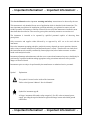
- Important Information! - Important Information! -
This Service Manual contains important warnings and safety instructions to be observed by the user.
This instrument is only intended for one area of application which is described in the instructions. The
most important prerequisites for installation, operation and safety, are explained to ensure safe and
reliable operation. No warranty or liability claims will be covered if the instrument is installed in areas
other than those described or if the necessary prerequisites and safety measures are not observed.
The instrument is intended to be operated by qualified personnel capable of observing these
prerequisites.
Only accessories and supplies either delivered by or approved by AVL are to be used with the
instrument.
Due to the instrument operating principles, analytical accuracy depends on correct operation, function,
and a variety of external influences beyond the manufacturer’s control. Therefore the test results from
this instrument must be carefully examined by licensed physician, before further measures are taken
based on the analytical results.
Instrument adjustment and maintenance with the covers removed and connected to power, should only be
performed by a qualified technician taking appropriate safety precautions and aware of the possible
dangers of electrical shock.
Instrument repairs are only to be performed by the manufacturer or authorized service personnel.
Symbol
!
Explanation:
This symbol is located on the inside of the instrument:
"Refer to the Operator's Manual / Service Manuals".
Symbol for instrument type B:
A B-type instrument falls under safety categories I, II or III, or has an internal power
supply, providing the required insulation against discharge current and reliable ground
connections.
- Important Information! - Important Information! -
- Operating Safety Information •
•
This instrument falls under Safety Category I.
This instrument is a Type B device.
This device complies with Part 15 of the FCC Rules. Operation is subject to the following two
conditions: (1) this device may not cause harmful interferences, and (2) this device must accept any
interference received, including interference that may cause undesired operation.
Warning: Changes or modifications to this unit not expressly appoved by the party responsible for
compliance could void the user’s authority to operate the equipment.
Note: This equipment has been tested and found to comply with the limits for a Class B digital device,
pursuant to Part 15 of the FCC Rules. These limits are designed to provide reasonable protection
against harmful interference in a residential installation. This equipment generates, uses, and can
radiate radio frequency energy and, if not installed and used in accordance with the instructions, may
cause harmful interference to radio communication.
However, there is no guarantee that intereference will not occur in a particular installation. If this
equipment does cause harmful interference to radio or television reception, which can be determined
by turning the equipment off and on, the user is encouraged to try to correct the interference by one
or more of the following measures:
• Reorient or relocate the receiving antenna
• Increase the separation between the equipment and the receiver
• Connect the equipment into an outlet on a circuit different from that to which the receiver is
connected
• Consult the dealer or an experienced radio/TV technician for help
CAUTION:
•
•
•
•
•
•
The main power cord may only be plugged into a properly grounded socket. When using an
extension cord, make sure it is properly grounded and fused.
Disconnection of the ground lead or a loose ground connection, inside or outside the instrument, may
yield unsafe or hazardous operation of the instrument. Intentional disconnection of the grounding
should be avoided.
When replacing fuses, make sure that the fuses used are of the specified type and rating. Never use
repaired fuses or short-circuit the fuse holders.
The instrument is designed as a closed conventional device which is not waterproof.
Do not operate the instrument in an environment with explosive or hazardous gases or in the vicinity
of
anesthetic gas mixtures containing oxygen or nitrous oxide.
The instrument is suitable for continous operation.
- Operating Safety Information -
Contents
CONTENTS
1 INTRODUCTION
General Information...................................................................................................................1-1
W arnings ..................................................................................................................................1-1
2 GENERAL DESCRIPTION
Specifications............................................................................................................................2-1
Principles of Operation ..............................................................................................................2-5
Fluidics Block Diagram ..............................................................................................................2-9
OPTI Cassette ........................................................................................................................ 2-10
OPTI Cassette Valve Positions ................................................................................................ 2-11
Assemblies ............................................................................................................................. 2-12
Software Structure OPTI 1 ....................................................................................................... 2-14
Software Structure OPTI CCA .................................................................................................. 2-21
3 INSTALLATION / MAINTENANCE
Environment ..............................................................................................................................3-1
Installation ................................................................................................................................3-2
Maintenance .............................................................................................................................3-4
4 MECHANICS
Pump Cartridge .........................................................................................................................4-1
Printer Assembly .......................................................................................................................4-1
Housing ....................................................................................................................................4-2
Sample Measurement Chamber Cover .......................................................................................4-2
SMC Lower Module ...................................................................................................................4-2
Handle ......................................................................................................................................4-2
Gas Manifold Module .................................................................................................................4-3
Display Assembly ......................................................................................................................4-3
Keypad .....................................................................................................................................4-3
Exhaust Fan ..............................................................................................................................4-4
Storage Compartment ...............................................................................................................4-4
Peristaltic Pump Motor ..............................................................................................................4-4
Battery Receptacle ....................................................................................................................4-4
Main Board Assembly ................................................................................................................4-5
Barcode Reader ........................................................................................................................4-6
1
Contents
5 ELECTRONICS DESCRIPTION
Main Board OPTI 1 - Electronic Circuits ....................................................................................5-1
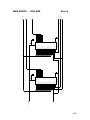
Block Diagram - Sheet 1 ..........................................................................................................5-3
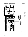
Component Location - Sheet 2 .................................................................................................5-3
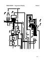
RAM Battery Backup and Clock - Sheet 3 .................................................................................5-3
Microprocessor - Sheet 4.........................................................................................................5-3
16 Bit EPROM - Sheet 5 ..........................................................................................................5-4
16 Bit Ram - Sheet 6 ...............................................................................................................5-4
Barcode and Serial Interface - Sheet 7 .....................................................................................5-4
Keypad and Display - Sheet 8 ..................................................................................................5-5
Cassette Detection Logic - Sheet 9 ..........................................................................................5-5
Battery Charger Circuit - Sheet 10 ...........................................................................................5-5
Voltage Regulator - Sheet 11 ...................................................................................................5-6
SMC Temperature Control - Sheet 12 ......................................................................................5-6
SMC Heat Transistor Circuit - Sheet 13....................................................................................5-6
SMC Heat Control - Sheet 14 ...................................................................................................5-7
Digital to Analog Converter - Sheet 15 .....................................................................................5-7
Analog to Digital Converter - Sheet 16 .....................................................................................5-7
Barometer - Sheet 17 ..............................................................................................................5-8
Motor Drive Control - Sheet 18.................................................................................................5-8
Printer Controller - Sheet 19 ....................................................................................................5-8
Cassette Detection Circuit - Sheet 20.......................................................................................5-9
Interconnect - Sheet 21 ...........................................................................................................5-9
Main Board Test Points ........................................................................................................... 5-10
Connector Listing .................................................................................................................... 5-11
Main Board OPTI CCA - Electronic Circuits ............................................................................. 5-18
Main Board Test Points ........................................................................................................... 5-22
Connector Listing .................................................................................................................... 5-24
2
Contents
6 TEST PROGRAMS AND DIAGNOSTICS
OPTI 1
Diagnostic 1..................................................................................................... 6-1
Barometer .........................................................................................................................6-1
Battery ..............................................................................................................................6-1
Temperature .....................................................................................................................6-2
Gas Pressure ....................................................................................................................6-2
Cleaning ...........................................................................................................................6-2
Flow Test ..........................................................................................................................6-3
Optics Test .......................................................................................................................6-3
Diagnostic 2..................................................................................................... 6-4
Printer Test .......................................................................................................................6-4
Keypad Test ......................................................................................................................6-4
Display Test ......................................................................................................................6-4
Barcode Test ....................................................................................................................6-4
RS232 Test .......................................................................................................................6-4
Cover Test ........................................................................................................................6-5
Fset ..................................................................................................................................6-5
Diagnostic 3..................................................................................................... 6-6
Valve Test.........................................................................................................................6-6
Valve Drive Test ................................................................................................................6-6
Peristaltic Pump Test ........................................................................................................6-6
LED Test...........................................................................................................................6-7
Memory Test .....................................................................................................................6-7
Software Version ...............................................................................................................6-7
Reports .....................................................................................................................................6-7
6 TEST PROGRAMS AND DIAGNOSTICS CONT'D
OPTI CCA
Diagnostic 1................................................................................................... 6-10
Barometer ....................................................................................................................... 6-10
Battery ............................................................................................................................ 6-10
Temperature ................................................................................................................... 6-11
Gas Pressure .................................................................................................................. 6-11
Version ........................................................................................................................... 6-11
Reports ........................................................................................................................... 6-11
Barcode .......................................................................................................................... 6-14
Diagnostic 2................................................................................................... 6-14
Printer Test ..................................................................................................................... 6-14
Optics Test ..................................................................................................................... 6-14
LED Test......................................................................................................................... 6-15
3
Contents
Interface Test.................................................................................................................. 6-15
IR Test............................................................................................................................ 6-15
Fan Test ......................................................................................................................... 6-15
Fset ................................................................................................................................ 6-16
Diagnostic 3 ................................................................................................... 6-18
Valve Test....................................................................................................................... 6-18
Flow Test ........................................................................................................................ 6-18
Display Test .................................................................................................................... 6-19
VDrive Test ..................................................................................................................... 6-19
Peristaltic Pump Test ...................................................................................................... 6-19
Keypad Test .................................................................................................................... 6-19
7 ADJUSTMENTS
OPTI 1Summary........................................................................................................................7-1
Barometric Pressure..................................................................................................................7-1
Sample Measuring Chamber Temperature..................................................................................7-1
OPTI CCA Summary..................................................................................................................7-2
Barometric Pressure..................................................................................................................7-2
Sample Measuring Chamber Temperature..................................................................................7-3
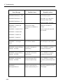
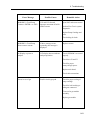
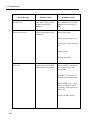
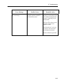
8 TROUBLESHOOTING
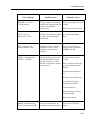
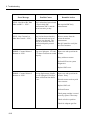
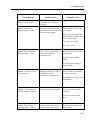
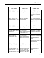
Displayed Alarms / Message Summary......................................................................................8-1
System Stop Alarms ..................................................................................................................8-2
System Error Alarms .................................................................................................................8-4
System W arning Messages........................................................................................................8-8
System Information Messages ................................................................................................. 8-11
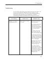
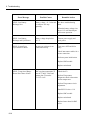
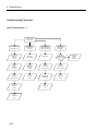
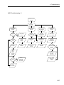
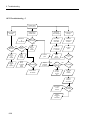
Troubleshooting ...................................................................................................................... 8-13
Troubleshooting Flowcharts ..................................................................................................... 8-24
4
Contents
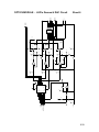
9 ELECTRONIC DIAGRAMS
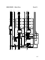
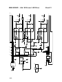
Main Board OPTI 1 - Electronic Diagram ....................................................... 9-1
OPTI 1 Block Diagram - Sheet 1 ......................................................................................9-2
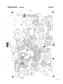
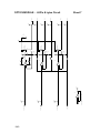
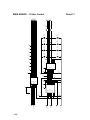
Layout - Sheet 2 ..............................................................................................................9-3
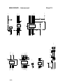
RAM Battery Backup and Clock - Sheet 3.........................................................................9-4
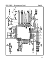
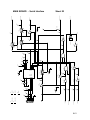
Microprocessor - Sheet 4.................................................................................................9-5
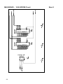
16 Bit EPROM - Sheet 5 ..................................................................................................9-6
16 Bit RAM - Sheet 6 .......................................................................................................9-7
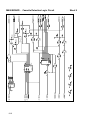
Barcode and Serial Interface - Sheet 7 .............................................................................9-8
Keypad and Display - Sheet 8 ..........................................................................................9-9
Cassette Detection Logic - Sheet 9 ................................................................................ 9-10
Battery Charger Circuit - Sheet 10 ................................................................................. 9-11
Voltage Regulator - Sheet 11 ......................................................................................... 9-12
SMC Temperature Control - Sheet 12 ............................................................................ 9-13
SMC Heat Transistor Circuit - Sheet 13.......................................................................... 9-14
SMC Heater Control - Sheet 14...................................................................................... 9-15
Digital to Analog Converter - Sheet 15 ........................................................................... 9-16
Analog to Digital Converter - Sheet 16 ........................................................................... 9-17
Barometer - Sheet 17 .................................................................................................... 9-18
Motor Drive Control - Sheet 18....................................................................................... 9-19
Printer Controller - Sheet 19 .......................................................................................... 9-20
Cassette Detection Circuit Sheet 20 ................................................................................ 9-21
Interconnection - Sheet 21 ............................................................................................. 9-22
Optic Module Circuit Diagrams ..................................................................... 9-23
Microprocessor - Sheet 1............................................................................................... 9-23
Photo Detector - Sheet 2 ............................................................................................... 9-24
Photo Detector Gain - Sheet 3 ....................................................................................... 9-25
Analog to Digital Converter - Sheet 4 ............................................................................. 9-26
Cassette Detection Circuit - Sheet 5 .............................................................................. 9-27
Heater Board SMC Top Plate ......................................................................... 9-28
Display Board Interconnect ........................................................................... 9-29
Printer Board Interconnect ............................................................................ 9-30
5
Contents
Electronic Diagrams OPTI CCA...................................................................... 9-31
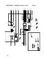
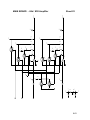
OPTI CCA Block Diagram - ............................................................................................ 9-32
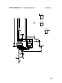
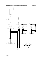
Component Location Layout............................................................................................. 9-33
Optic Module Circuit Diagrams ...................................................................... 9-34
Optics
Optics
Optics
Optics
Optics
Optics
Optics
Optics
Module
Module
Module
Module
Module
Module
Module
Module
-
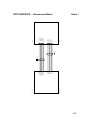
Digital Circuit Sheet 1 ............................................................................. 9-34
Amplifier Circuit Sheet 2 ......................................................................... 9-35
Amplifier Circuit Sheet 3 ......................................................................... 9-36
Inverter Circuit Sheet 4 ........................................................................... 9-37
A/D Converter Circuit Sheet 5 ................................................................. 9-38
LED's, Gasses & DAC Circuit Sheet 6 ..................................................... 9-39
LED's & Lytes Circuit Sheet 7 ................................................................. 9-40
Connector Circuit Sheet 8 ....................................................................... 9-41
Main Board Circuit Diagrams ......................................................................... 9-42
Main
Main
Main
Main
Main
Main
Main
Main
Main
Main
Main
Main
Main
Main
Main
Main
Main
Main
Main
Main
Main
Main
Main
6
Board
Board
Board
Board
Board
Board
Board
Board
Board
Board
Board
Board
Board
Board
Board
Board
Board
Board
Board
Board
Board
Board
Board
-
RAM Battery Backup / Clock Sheet 1 ........................................................ 9-42
Microprocessor Sheet 2............................................................................ 9-43
16 Bit EPROM Sheet 3 ............................................................................. 9-44
16 Bit RAM Sheet 4 .................................................................................. 9-45
Barcode Interface Sheet 5 ........................................................................ 9-46
Keypad and Display Sheet 6 ..................................................................... 9-47
Cassette Detection Logic Sheet 7 ............................................................. 9-48
Battery Charger Sheet 8 ........................................................................... 9-49
Voltage Regulator Sheet 9........................................................................ 9-50
SMC Temperature Control Sheet 10 ......................................................... 9-51
SMC Heater Transistor Sheet 11 .............................................................. 9-52
SMC Heater Control Sheet 12................................................................... 9-53
Digital to Analog Converter Sheet 13 ........................................................ 9-54
Analog to Digital Converter Sheet 14 ........................................................ 9-55
Barometer Sheet 15 ................................................................................. 9-56
Motor Drive Sheet 16 ............................................................................... 9-57
Printer Control Sheet 17 ............................................................................ 9-58
Cassette Detect Sheet 18 ......................................................................... 9-59
Interconnect Sheet 19 .............................................................................. 9-60
Serial Interface Sheet 20 .......................................................................... 9-61
tHb / SO2 Laser / LED Driver Sheet 21 ..................................................... 9-62
tHb / SO2 Amplifier Sheet 22.................................................................... 9-63
Over Temperature Protection Sheet 23 ..................................................... 9-64
Contents
SMC Module .................................................................................................. 9-65
Optics
Optics
Optics
Optics
Module
Module
Module
Module
Interconnect - Sheet 1............................................................................. 9-65
LED's, Gasses & Heater - Sheet 2 ........................................................... 9-66
LED's, ION's & Heater - Sheet 3 .............................................................. 9-67
SMC Heater/tHb Board - Sheet 4 ............................................................. 9-68
Display Board IR............................................................................................ 9-69
Display IR Board - Interconnect Sheet 1 ........................................................................ 9-69
Display IR Board - IR Circuit Sheet 2 ............................................................................ 9-70
10 ILLUSTRATED PARTS LIST
Spare Parts List ...................................................................................................................... 10-1
Main Upper Housing (Outer View) ............................................................................................ 10-2
Main Upper Housing (Inner View) ............................................................................................. 10-4
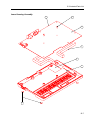
Lower Housing Assembly......................................................................................................... 10-6
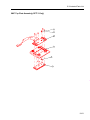
Printer Assembly ..................................................................................................................... 10-8
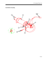
SMC Assembly ...................................................................................................................... 10-10
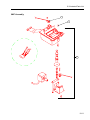
Gas Module Assembly ........................................................................................................... 10-12
Display Assembly .................................................................................................................. 10-14
Battery Receptacle Assembly................................................................................................. 10-16
SMC Top Cover Assembly ..................................................................................................... 10-18
SMC Top Plate Assembly(OPTI 1 Only).................................................................................. 10-20
11 SERVICE SPARE PARTS
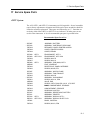
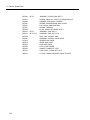
Spare Parts List ...................................................................................................................... 11-1
7
1 Introduction
1 Introduction
OPTI System
General Information
This Service Manual includes information and data necessary for repair and
maintenance of the OPTI 1 and OPTI CCA analyzers. The manual is intended to be
used with the Operator’s Manual where operating instructions and procedures are
described. In order to fully utilize the described procedures in this manual, it is
necessary to be familiar with the operation and handling described in the Operator’s
Manual.
To ensure proper operation and performance which meets the analyzer specifications,
maintenance and repairs must be performed according to the instructions described in
this service manual. The use of AVL original parts and recommended materials is
required to achieve performance specifications. Spare parts and the proper order
numbers are described in Chapters 10 and 11.
Product warranties may vary by country. Specific warranty terms and conditions are
described in documents provided at the time of installation.
Warnings
Warnings in this manual are marked with CAUTION and describe situations or
potential dangers that may be hazardous to personnel performing maintenance or
service activities. Information marked with NOTE describes situations or hazards,
which can cause damage or analyzer malfunction and should be avoided. The
following general operating conditions should be strictly adhered to:
•
Never operate the analyzer near flammable or explosive gases.
•
Check the supply voltage before connecting the analyzer to local AC power.
•
When operating the analyzer connected to primary AC power, always connect it to
a properly grounded 3-pole power receptacle.
•
Replace damaged or worn power cables or plugs.
•
Before opening the rear cover, turn off the analyzer and disconnect the power
cable from the primary AC source.
•
Replace fuses with approved or original types only.
1-1
1 Introduction
1-2
•
Operate the analyzer away from sources of liquids such as sinks or wash basins.
•
Avoid leakage or spilling of fluids inside the analyzer, which may damage the
electrical assemblies.
•
Clean the analyzer surfaces with only a mild soapy solution as necessary. Avoid
strong or harsh chemical cleaning agents that may damage the analyzer housing
and surfaces.
•
Use proper tools and test equipment as described in this manual to complete
testing and repairs.
•
Analyzer surfaces may be contaminated from contact with blood. Always use
precaution when contacting these surfaces.
•
Use approved protective gloves when handling blood specimens of contacting
contaminated surfaces.
•
Adhere to local regulations when disposing of OPTI cassettes or contaminated
parts.
2 General Description
2 General Description
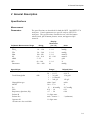
Specifications
Measurement
Parameters
The specifications are described for both the OPTI 1 and OPTI CCA
analyzers. Certain parameters are specific only to OPTI CCA
analyzers. The specifications listed below are valid for human
whole blood, pH of human plasma, serum, and approved QCmaterial.
Validated Measurement Range
pH
PCO 2
PO 2
Na+
K+
ctHb
SO 2
Barometer
Range
6.6 - 7.7
10 - 120
20 - 500
100 - 180
0.8 – 10.0
5 – 25
60 – 100
300 - 800
Input Values
Units
0.01 / 0.001
1 / 0.1
1 / 0.1
1 / 0.1
0.1 / 0.01
0.1
1 / 0.1
0.1
pH units
mmHg
mmHg
mmol/L
mmol/L
g/dL
%
mmHg
Range *
Patient Temperature
Temp
Total Hemoglobin
tHb
Hemoglobin type
MCHC
P 50
FIO 2
Respiratory Quotient, RQ
Patient Id
Patient Sex
Operator Id
Display
Resolution
(Lo / Hi)
14 - 44 °C
58 - 111 °F
1 - 26 g/dL
1 - 16 mmol/L
1 - 260 g/L
adult / fetal
30.0 – 37.0
15 - 40 mmHg
0.21 - 1.0
0.7 - 2.0
11 digits max.
male / female / ?
11 digits max.
Default Value
37.0 °C
98.6 °F
15.0 g/dL
150 g/L
adult
%
26.7 mmHg
0.21
0.84
? (unknown)
*SI units are also available.
2-1
2 General Description
Calculated Values
Range
Display
Resolution
Base excess in vitro
Base excess in vivo
BE
BEecf
Base excess actual
Buffer base
BEact
BB
0 - 100
0.1
mmol/L
Actual bicarbonate
HCO 3 -
1 - 200
0.1
mmol/L
Total CO 2
TCO 2
1 - 200
0.1
mmol/L
Standard bicarbonate
stHCO 3 -
1 - 200
0.1
mmol/L
Standard pH
stpH
6.5 - 8.0
0.001
pH units
Oxygen saturation
O 2 sat
0 - 100
0.1
%
Oxygen content
O 2 ct
0 - 56
0.1
vol%
1000 - 10
0.1
nmol/L
+
-40 - +40
-40 - +40
-40 - +40
0.1
Units
0.1
mmol/L
mmol/L
0.1
Hydrogen ion
concentration
Alveolar-arterial oxygen
partial pressure difference
cH
AaD O2
0 - 800
0.1
mmHg
P50
P50
15 - 35
0.1
mmHg
Anion Gap
AnGp
Normalized Ca++
nCa++
Hematocrit, Calculated
Hct(c )
15 - 75
1
PCV%
Data Management
Printout
Serial Interface
built-in thermoprinter
1x RS 232, 9-pin SUBMIN D/F
Infrared Interface
1XIR (Unidirectional or
Bi-directional)
Gas Supply
Calibration Gas
2-2
14 % O 2 , 6 % CO 2 , balance N 2 ,
max. pressure 145 psi (10 bar)
ASCII or
ASTM
ASTM
2 General Description
Operating Parameters
Sample type
Sample input device
Sample size
Sample input
Analysis time
Type of measurement
Units
Heparinized whole blood, plasma/serum (pH
only), AVL approved quality control materials
syringe, capillary, microsampler
OPTI 1
80µL
OPTI CCA 125µL
automatic aspiration
< 2 minutes
Optical fluorescence and reflectance
conventional, standard international (SI)
Temperature /
Humidity
Ambient temperature
Measuring chamber
temperature
Relative humidity
15 °C - 32 °C
37 °C ± 0.1 °C
(60 °F - 90 °F)
(98.6 °F ± 0.18 °F)
5 - 95 % non-condensing
Electrical Supply
Voltage range
Frequency
Power consumption
90 - 250 VAC,
50 - 60 Hz
typical 110 VA
Classification
Safety category
Instrument type
Operation type
Protective system
Ex - protection
I
B (following ÖVE - MG/EN 60 601-1, IEC
601-1 with optional power supply)
For continuous operation
IP20
The device is not specified for operation inside
explosion hazardous areas.
Dimensions / Weight
Height
Width
Depth
Weight
4.875
14.25
4.75
10.5
inches (12.4 cm)
inches (36.2 cm)
inches (27.8 cm)
pounds (4.8 kg ) with battery
2-3
2 General Description
Acoustic Noise Level
standby
ready
wash/dry
measurement
28
28
60
43
dbA
dbA
dbA
dbA
Test Certificates
CSA
CE
2-4
2 General Description
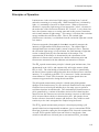
Principles of Operation
Luminescence is the emission of light energy resulting from "excited"
molecules returning to a resting state. When luminescence is initiated by
light, it is commonly referred to as fluorescence. When a fluorescent
chemical is exposed to light energy of an appropriate "color", electrons in
the molecules of the fluorescent chemical are "excited". A very short time
later, the electrons return to a resting state and in this process sometimes
emit a small amount of light energy. This energy is less than the excitation
energy and thus has a different color. That is, the emitted light
(fluorescence emission), is red-shifted from the excitation light and is much
less intense.
Fluorescent optodes (from optical electrodes) essentially measure the
intensity of light emitted from fluorescent dyes. The emitted light is
distinguished from excitation light by means of optical filters. Because
the excitation light energy is kept constant, the small amount of light that
results is changed only by the concentration of the analyte. The
concentration of the analyte is determined by the calculation of the
difference in fluorescence measured at a known calibration point and
fluorescence measured with the unknown concentration of analyte.
The P O 2 optode measurement principle is based upon luminescence, first
documented in the 1930's, and commercially utilized to measure blood
P O 2 in 1983. The relationship of luminescence to P O 2 is quantified by
the Stern-Volmer equation which describes how the fluorescence emission
intensity "I" is reduced as the PO 2 "P" is increased. Unlike conventional
electrochemical "Clark" P O 2 electrodes, the oxygen optode does not
consume oxygen molecules during the measurement.
The pH optode measurement principle is based upon pH-dependent
changes of the luminescence of a dye molecule immobilized in the optode.
Chemists have used such pH indicator dyes for many years to perform
acid-base titrations in turbid media. The relationship of luminescence to
pH is quantified by a variant of the Mass-Action Law of chemistry that
describes how the fluorescence emission intensity increases as the blood
pH is increased above the dye's characteristic pKa. pH optodes do not
need a reference electrode to measure pH; however, they exhibit a small
sensitivity to the ionic strength of the sample being measured.
The PC O 2 optode measurement principle is based upon placing a pH
optode behind an ion-impermeable membrane, just as conventional PC O 2
blood gas electrodes employ the Severinghaus C O 2 electrode construction.
As such, PC O 2 optodes suffer from non-selective interference from
volatile acids and bases in blood just as conventional PC O 2 electrodes.
2-5
2 General Description
During the measurement, light originating from lamps in the analyzer is
passed through optical filters so that specific colors are transmitted to
the sensors, causing them to emit fluorescence. The intensity of this
emitted light depends upon the partial pressure of oxygen (P O 2 ),
carbon dioxide (P O 2 ) or hydrogen ion concentration (pH) of the blood
in direct contact with the sensors, as described above. The light
emitted by the fluorescent sensors passes through lenses and additional
optical components. A filter is used to isolate specific colors of
interest from this returning light for measurement by a light detector.
The Na and K ion optodes are based upon the principle of Ion Selective
Electrodes (ISE’s). The optodes use ion selective recognition elements
(ionophores) similar to those used in ISE’s, however the ionophores are
linked to fluorescent dyes instead of electrodes. These types of dyes
have been used since the 1970’s to visualize and quantify cellular ion
levels in fluorescence microscopy and cell counters 8 . As the ion
concentration increases, these ionophores bind larger amounts of ions
and cause the fluorescence intensity to increase or decrease, depending
on the particular ion. Like the pH optode, the ion optodes do not need
a reference electrode, however they do exhibit a small pH sensitivity
that is automatically compensated in the AVL OPTI using the measured
pH.
The measurement of total Hemoglobin (ctHb) and oxygen saturation
(SO 2 ) uses the well-established principle of optical reflectance. Red
and infrared light a three wavelengths is directed at whole, nonhemolyzed blood within a precisely defined part of the cassette over the
O2 optode. The photons are partially absorbed and reflected by
erythrocytes in a manner proportional to hemoglobin level; at low
hemoglobin levels the unabsorbed photons strike the O2 optode’s pink
overcoat and are reflected back up through the blood a second time. A
portion of the reflected light exits the top of the cassette and is
measured by a detector in the instrument. The infrared wavelengths are
selected for the hemoglobin measurement because they are largely
independent of SO2, that is, the predominate forms of adult and fetal
hemoglobin absorb similarly within the 750 – 850 nm wavelength
range. The red wavelength is utilized for the SO2 measurement
because it is much more strongly absorbed by deoxyhemoglobin than
all other hemoglobins, and is picked close to the isobestic point for
oxy- and carboxyhemglobin. Maintaining high shear force just prior to
measurement minimizes sensitivity to erythrocyte aggregation (rouleau
formation).
The optical signal of the detectors is converted by the microprocessor
to a numerical readout in conventional units of measure and displayed
on the front of the device. Other values commonly used for the
assessment of oxygen and acid-base status are calculated from these
measured values.
2-6
2 General Description
The entire sample path of the OPTI cassette is filled with storage buffer
to keep the sensors stable during storage. In addition, the cassette
pouch is filled with a CO 2 atmosphere, which keeps the pH of the
storage buffer stable.
The cassette not only contains the sensors but also houses a distribution
valve (cassette valve), the sample fill port, an input/output port (I/O
port), a reservoir and a vent.
The function of the I/O port is to connect the cassette to the peristaltic
pump allowing sample aspiration and calibration gas to flow through
the cassette.
The storage buffer in the reservoir ensures stability over the shelf life
of the cassette.
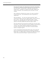
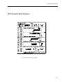
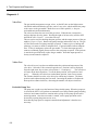
The distribution valve has 2 functions: its hollow body serves as a
waste container, referred to as “waste”, holding storage buffer and
OPTI-trol. In addition, the cassette valve incorporates small channels,
called links that connect the sensor channel, the fill port, the vent and
the I/O port in different combinations. These different connections are
achieved by turning the cassette valve to different positions. Each
valve position has an assigned number. An unused cassette is set to
position 0, the home position. The diagram on page 2-9 shows the
valve positions and the connections for each position. E.g., position 2
connects the fill port via the valve link to the sensor channel and the
reservoir to the I/O port.
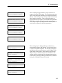
The OPTI 1 and OPTI CCA analyzers are microprocessor-based
instruments measuring optical fluorescence. The disposable, single-use
cassette contains all the elements needed for calibration, sample
measurement and waste containment. After reading the calibration
information specific to a cassette into the instrument by 'swiping' the
cassette package through a convenient bar code reader, the cassette is
placed in the measurement chamber. While the analyzer warms the
cassette to 37.0 ± 0.1 °C, the cassette valve is turned to position 5. In
this position, the I/O port is connected to the vent allowing the pump to
purge calibration gas. At the same time, readings are taken from all
sensors to ensure proper functioning. In addition, the fluid light gates
L1, L2 and L3 are calibrated.
Then the valve turns to position 1 which connects the I/O port to the
reservoir and the cassette sensors to the vent via the waste. The pump
starts pushing the storage buffer into the waste. L1 and L2 monitor the
movement of the buffer and the pump rate. After the buffer is pushed
into the waste, the valve turns to position 4, which connects the I/O
port to the reservoir and the sensors directly to the vent. The pump
2-7
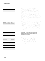
2 General Description
first purges the cassette with calibration gas, then slows down during
the actual gas calibration passing the gravimetrically prepared gas mix
across the sensors. The pH sensor is calibrated via the precision
storage buffer. Calibration is completed when stable readings of all
sensors are obtained. The calibration process lasts from 15 to 80
seconds.
After calibration verification, the cassette valve turns to position 8
closing off all ports. The instrument now waits for aspiration of
sample fluid.
After pressing the J key, the valve turns to position 2, which
connects the fill port to the sensor channel and the reservoir to the I/O
port via waste. The pump starts aspirating the sample. During
aspiration, the sample light gates L1 and L2 check for sample type
(blood or clear fluid), bubbles and sufficient sample volume.
Once the sample has been aspirated successfully, the valve turns again
to position 4. After a short warm-up period, readings are taken from all
3 sensors. Once stable readings are obtained, the valve turns to
position 8 closing off all ports. The results are calculated and the
cassette is ready for disposal.
In case of an OPTI-trol measurement (OPTI 1 only), the user has the
option of terminating the measurement or introducing a subsequent
blood sample. If a blood sample is introduced, the OPTI-trol is purged
into the waste and the blood sample is aspirated and analyzed.
2-8
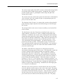
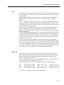
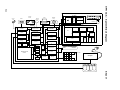
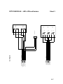
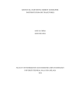
Gas Valve
Fig. 2-1: Fluidics Block Diagram
NO
Air
Gas Manifold
Assembly
Low
Pressure
Switch
Calibration Gas
6.0% CO2 14% O2
(140 psi)
NC
COM
Fluidics Block Diagram
Regulator
(2.5 psi)
Three
Way
Valve
Peristaltic Pump
and
Cartridge
Sample Casette
2 General Description
2-9
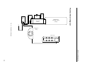
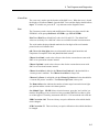
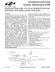
2 General Description
OPTI Cassette
Finger Grip
Vent
Valve/Waste
Location of Fluid Light Gate (L1)
pH Sensor
O2 Sensor
CO2 Sensor
Location of Fluid Light Gate (L2)
Key
Fill
Port
Location of Cassette
Detect Sensor
(CDETECT)
Valve Key
Slots
Na
Sensor
Finger Grip
Input/Output
Port
Cl/Ca
Sensor
Location of Fluid Light
gate (L3)
Fig. 2-2: OPTI 1 Cassette
2-10
K
Sensor
Cassette
Body
2 General Description
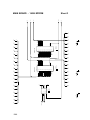
OPTI Cassette Valve Positions
Fig. 2-3: OPTI Cassette Valve Positions
2-11
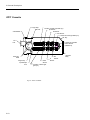
2 General Description
Assemblies
The OPTI consists of several major components and assemblies that
control the operation of the analyzer. A brief function description of
the assemblies is provided below.
Valves
Modular
Components
Valve
The gas valve module controls the delivery of the internal
calibration gas. The gas valve module incorporates a
pressure regulator, pressure sensor, gas valve and a threeway valve.
Vdrive
The valve drive assembly is a stepper motor that controls the
positioning of the cassette valve.
Pump
The peristaltic pump assembly is a stepper motor and pump
cartridge that provides for the pump flow used to transport
sample and calibrator material through the cassette.
• The sample measurement chamber (SMC) assembly provides
thermostated heating control of the measuring chamber at
37 °C ± 0.1 °C (98.6 °F ± 0.18 °F).
• The optics module is a microprocessor-based assembly that houses
the optics detectors, preamplifiers and processing circuitry for
optode sensor signals.
• The main board includes the main microprocessor, RAM and
EPROM memory and control circuitry for the LCD display,
keyboard, printer motors, barcode and serial interface.
• The OPTI Cassette contains the optode sensor used to measure the
sample and also includes the reservoir for reagent and sample waste.
•
The OPTI CCA (only) SMC Cover provides optics and processing
circuitry for ctHb/SO2 measurement.
•
A minimal amount of tubing is used in the OPTI system.
•
Storage compartment.
• Liquid crystal display, 2 lines x 24 characters per line.
•
Keyboard with numeric keys, l and r keys, J and E keys.
• Thermoprinter.
• Serial RS 232 C - interface
• Barcode reader
2-12
2 General Description
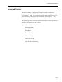
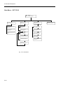
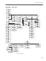
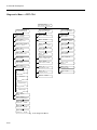
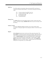
Software Structure
The OPTI software is designed to provide a simple user interface
organized in a menu fashion. The operator may select a menu function
by using the l and r keys to move to the desired menu selection. The
menu function to be selected will be blinking. Pressing the J key
will select the desired menu item.
The following system software menus are provided in flow chart format
and show the software menu structure:
Main Menu
Sampling Menu
Run Menu
Data Menu
Setup Menu
Diagnostic Menu
QC - Range Setup Menu
2-13
2 General Description
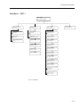
Main Menu – OPTI 1
RUN: SRCs Controls
Data Time/Date Setup Diag
SRC
Controls
Data
Setup
Run SRC
Run Controls
Pat Reports
BP
SRC Reports
Patient Info
Time/Date
Diag
Diag 1
Barometric
Pressure
Battery Voltage
Patient Report
Temperature
Control Reports
Print
# of Copies
Gas Pressure
Cal Report
Export
Calc Param
Clean
Password
Flow Test
QC Lockout
Optics
Security
Misc
Diag 2
Units
Printer
Keypad
Display
Correlation
Barcode
Comm
RS232
Language
Cover
FSet
Battery
Diag 3
Valve
V Drive
Pump
LEDs
Memory
Version
Reports
Fig. 2-4: Main Menu
2-14
2 General Description
Sampling Menu – OPTI 1
Power
On
AVL OPTI 1
Please Wait
Calibrating
60
Input Pat. Data <ENTER>
Patient Sample
Pat ID: XXXXXXXXXXX
Purging Please Wait
Please Wait
Rev AOPX1.10
Calibration OK
Place Sample Now
599
66
Please Wait
89
Input Pat. Data <ENTER>
Purging Gas System
55
Aspirating Sample
Input Pat. Data <ENTER>
Warm Up
37.0 C
MENU <ENTER>
200
Measuring Sample
90
Input Pat. Data <ENTER>
READY - Cassette Barcode
MENU <ENTER>
Patient Sample
Op ID: XXXXXXXXXXX
Patient Sample
Temp: 37.0 C
Patient Sample
THb: 15.0 g/dL
Patient Sample
Sex: ? MALE FEMALE
Measurement Completed
Patient Sample
FIO2: 0.21
Swipe Cassette
Barcode
pH PCO2
7.437 35.6
Run Opti-trol Controls?
NO YES
PO2
84.9
O2Sat
98.7
*YES
(see Run
Menu)
Press ESC
NO
Insert Cassette
Patient Sample
Hb Type: Adult Fetal
Patient Sample
P50: 26.7 mmHg
Please Remove Cassette
Patient Sample
RQ: 0.84
Cassette Inserted
Next Sample <ESC>
Input Pat. Data <ENTER>
Please Wait
Checking Cassette
Calibrating
90
Place Sample <ENTER>
Please Wait
MENU <ENTER>
__________________
AVL OPTI 1
Patient Report
* if Opti-trol selected
Fig. 2-5: Sampling-Menu
2-15
2 General Description
Run Menu – OPTI 1
RUN: SRC Controls
Data Time/Date Setup Diag
SRC
SRC Measurement
Op ID: XXXX
Swipe SRC Barcode
Controls
Data
Run Controls
Op ID: XXXXXXXX
Data: Patient
SRC Controls Export
Run Controls
Level: 1 2 3
Time/Date
Setup
Time: 08:51:23
Date: 15-Feb-95
Please enter PW2
Password <ENTER>
To Data Menu
To Setup Menu
if OPTI-trol is selected
Insert SRC
Run Controls Level 1
Lot #:xxxxxx <ENTER>
Run OPTI-trol Controls
Op ID: XXXXXXXX
Insert SRC
Swipe Cassette Barcode
to run Control
DATA - Controls
StatsReprt: All L1 L2 L3
SRC Inserted
Insert Cassette
Run OPTI-trol Level 1
Lot #:xxxxxx <ENTER>
SRC Measurement 160
Optics Module Warmup
Cassette Inserted
Swipe Cassette Barcode
to run Control
SRC Measurement 73
Reading SRC Signals
Please Wait
Checking Cassette
Insert Cassette
pH PCO2 PO2 Test
7.354 43.6 103.4 Pass
Calibrating
Please Open Cover
Calibration OK
Place Control Now<Enter>
Calibration OK
XXX
Place Control Now<Enter>
Please Remove SRC
Aspirating Control
pH
PCO2 PO2 Test
7.238 45.3 101.8 Pass
Printed Results
Measuring Control
99
Cassette Inserted
Accept Results <ENTER>
Reject / Edit
<ESC>
90
pH
PCO2 PO2 Test
7.238 45.3 101.8 Pass
Edit
<ESC>
Reject Results <ENTER>
Place Sample <ENTER>
or End <ESC>
<ENTER>
Accept Results <ENTER>
Reject / Edit
<ESC>
Please Remove Cassette
Printed Results
Esc
Edit
<ESC>
Reject Results <ENTER>
Aspirating Sample
Input Pat. Data <ENTER>
Run Controls
Op ID: XXXXXXXXXXX
Measuring Sample
Input Pat. Data <ENTER>
Run Controls
Level: 1 2 3
pH PCO2 PO2 O2Sat
7.388 44.6 159.7 99.4
Run Controls Level 1
Lot #: XXXX <ENTER>
Fig. 2-6: Run Menu
2-16
Diag
<ESC>
Please Remove Cassette
To Diag Menu
2 General Description
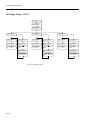
Data Menu – OPTI 1
Data: Patient
SRC Controls Export
Data - Patient
Report: Last Last5
Data - SRC
Report: Last5 Statistic
Data - Controls
Ranges Statistics Type
Last: Displays and Prints last
patient result
Last 5: Prints last 5
SRC results
Data - Control Ranges
Control Level: 1 2 3
Last 5: Prints last 5
patient results
Statistics: Prints
statistic report for all levels
Control Level x xxxxxx
Change Lot No: N Y
All: Prints all patient results in
memory
Please Wait
Control Level x xxxxxx
Print Old Data: N Y
Data - SRC
Delete All SRC Data N/Y
Control Level x xxxxxx
Delete Old Data: N Y
All
Data - Export
Patient SRC
Controls
(Enter PW2)
Please Enter PW2
Password <ENTER>
SRC Database deleted
Control Level x xxxxxx
New Lot No: xxxxxx
Control Level x xxxxxx
Exp Date: 23-Feb-95
Control Level x xxxxxx
pH: 6.900 - 7.700
Control Level x xxxxxx
PCO2: 10.0 - 120.0
Control Level x xxxxxx
PO2: 20.0 - 500.0
Data - Controls
StatsReprt: All
L1
L2
L3
Data - Controls - Type
Normal
OPTI-trol
Fig. 2-7: Data Menu
2-17
2 General Description
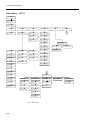
Setup Menu – OPTI 1
Setup
Please enter PW2
Password <ENTER>
Setup:Baro Pat.Info Prnt
CalcPar. Security Misc.
Barometer
SETUP - Please enter the
Baro: 727.3 mmHg
Patient Info
Print
SETUP - Patient Info
ON/OFF Defaults Limits
Calculated Parameters
SETUP - Print
Patient Report: OFF ON
SETUP - Calc Parameter
BE: OFF ON
Order 1
SETUP - Print
Number Copies: 1 2
SETUP - Calc Parameter
O2 Sat: OFF ON Order 2
SETUP - Print
Cal.Report:
OFF ON
SETUP - Calc Parameter
BB: OFF ON
Order 7
SETUP - Calc Parameter
HCO3: OFF ON Order 3
SETUP - Calc Parameter
st.HCO3:OFF ON Order 8
SETUP - ON/OFF
Patient ID: OFF ON
SETUP - Defaults
tHb: 15.0 g/dl
SETUP - Limits
pH: 7.350 - 7.450
SETUP - ON/OFF
PatID: Optional Required
SETUP - Defaults
FIO2: 0.21
SETUP - Limits
PCO2: 35.0 - 45.0
SETUP - ON/OFF
Operator ID: OFF ON
SETUP - Defaults
RQ: 0.84
SETUP - Limits
PO2: 80.0 - 100.0
SETUP - ON/OFF
OpID: Optional Required
SETUP - Defaults
P50: 26.7
SETUP - Calc Parameter
tCO2: OFF ON Order 4
Security
Miscellaneous
1
SETUP - Security
Password QC-LockOut
SETUP - Password
None PW1 PW2 PW1+2
SETUP - QC-Lockout
None SRC Controls NewLot
SETUP - Password
Please Enter PW: XXXXX
SETUP - Calc Parameter
st.pH: OFF ON Order 9
SETUP - Calc Parameter
AaDO2: OFF ON Order 5
SETUP - Calc Parameter
BEecf: OFF ON Order 10
SETUP - Calc Parameter
O2ct: OFF ON Order 6
SETUP - ON/OFF
Temp: OFF ON
SETUP - ON/OFF
tHb: OFF ON
SETUP - ON/OFF
Sex: OFF ON
1
SETUP - Misc
Unit Corr Comm Lang Bat
SETUP - ON/OF
FIO2: OFF ON
SETUP - ON/OFF
Hb Type: OFF ON
SETUP - Units
Units: Conventional SI
SETUP - Correl. Factors
pH Slope: 1.00
SETUP - Comm
Baud Format
SETUP - ON/OFF
P50: OFF ON
SETUP - Units
Temp: C F
SETUP - Correl. Factors
pH Offset: 0.000 + -
SETUP - Comm - Baud
Baud Rate (<>): 9600
SETUP - ON/OFF
RQ: OFF ON
SETUP - Units
Time: 12 hr 24 hr
SETUP - Correl. Factors
PCO2 Slope: 1.00
SETUP - Comm - Format
ASCII ASTM
SETUP - Units
tHb: g/dL g/L mmol/L
SETUP - Correl. Factors
PCO2 Offset: 0.000 + -
SETUP - Correl. Factors
PO2 Slope: 1.00
SETUP - Correl. Factors
PO2 Offset: 0.000
+ -
Fig. 2-8: Setup Menu
2-18
SETUP - Language
Engl Deut Japn Fran Esp
SETUP - Battery Saver
AutoOff: 60 10 AlwaysOn
SETUP - Display Light
AutoOff AlwaysOn
2 General Description
Diagnostic Menu – OPTI 1
RUN: SRC Controls
Data TimeDate Setup Diag
DIAG1:Baro Batt Temp Gas
Clean Flow TestOptics >
DIAG2: Printr Keypd Displ
Barcode RS232 Cover Fset >
DIAG3: Valve VDrive Pump
LEDs Mem Vers Reports >
DIAG1: - Barometer
Baro: 731.9 mmHg
DIAG2: - Printer Test
DIAG3: - Valve
Valve: ON OFF
DIAG1: - Battery
Battery Voltage: 12.9 V
DIAG2: - Keypad
Key:
DIAG3: - VDrive
Position: 0
DIAG1: - Temp. T3:31.48
T1:37.31
T2:37.01
DIAG2: - Display Test
DIAG3: - Pump
Pump Speed: 75
DIAG1: - Gas
Gas Pressure: High
DIAG2: - Barcode
Barcode:
DIAG3: - LEDs LT1:0 LT2:0
L1: 2614 L2: 2988 CD: 519
DIAG1: - Gas
Purge <ENTER> or <ESC>
DIAG2: - Interface
RS232-Jumper2-3 <ENTER>
DIAG3: - Memory
Memory OK
DIAG1: - Cleaning
Remove PumpCart<ENTER>
DIAG2: - Cover
Cover: Closed
DIAG3: - Version
Version: AOPX1.10
DIAG1: - Cleaning
Place Syringe
<ENTER>
Password
DIAG3: - Report
Errors Calibns SRCs Config.
DIAG1: - Cleaning
Perform Wash
<ENTER>
<ENTER>
AVL OPTI 1
Error Report
AVL OPTI 1
Calibration Report
DIAG3: - Version
Optics: OPTIC2B
AVL OPTI 1
SRC Report
AVL OPTI 1
Config. Report
DIAG1: - Cleaning
Reinsert Pump
<ENTER>
DIAG1: - Flow Test
Insert Cassette
<ENTER>
DIAG1: - Flow Test
Test in Process ......
DIAG1: - Flow
Pass:
4.54 5.70
<ENTER>
DIAG1: - Flow Test
Discard Cassette
DIAG1: - Test Optics
DIAG1: - Optics Test
Insert Cassette <Enter>
DIAG1: - Test Optics
Test in Process ..
DIAG1: - Test Optics
Remove Cassette
Fig. 2-9: Diagnostic Menu
2-19
2 General Description
QC-Range Setup – OPTI 1
Data - Controls
Ranges Statistics Type
Please Enter PW2
Password <ENTER>
Data - Control Ranges
Control Level: 1 2 3
Control Level 1 xxxxxx
Change Lot #: N / Y
Yes
No
Control Level 2 xxxxxx
Change Lot #: N / Y
Yes
No
Control Level 3 xxxxxx
Change Lot #: N / Y
Yes
No
Control Level 1 xxxxxx
pH: 6.900 - 7.700
Control Level 1 xxxxxx
Print Old Data: N / Y
Control Level 2 xxxxxx
pH: 6.900 - 7.700
Control Level 2 xxxxxx
Print Old Data: N / Y
Control Level 3 xxxxxx
pH: 6.900 - 7.700
Control Level 3 xxxxxx
Print Old Data: N / Y
Control Level 1 xxxxxx
PCO2: 10.0 - 120.0
Control Level 1 xxxxxx
Delete Old Data: N / Y
Control Level 2 xxxxxx
PCO2: 10.0 - 120.0
Control Level 2 xxxxxx
Delete Old Data: N / Y
Control Level 3 xxxxxx
PCO2: 10.0 - 120.0
Control Level 3 xxxxxx
Delete Old Data: N / Y
Control Level 1 xxxxxx
PO2: 20.0 - 500.0
Control Database
Deleted
Control Level 2 xxxxxx
PO2: 20.0 - 500.0
Control Database
Deleted
Control Level 3 xxxxxx
PO2: 20.0 - 500.0
Control Database
Deleted
Control Level 1 xxxxxx
New Lot No: 111111
Control Level 2 xxxxxx
New Lot No: 222222
Control Level 3 xxxxxx
New Lot No: 333333
Control Level 1 xxxxxx
Exp. Date: 31-Dec-95
Control Level 2 xxxxxx
Exp. Date: 31-Dec-95
Control Level 3 xxxxxx
Exp. Date: 31-Dec-95
Fig. 2-10: QC Ranges Setup
2-20
2 General Description
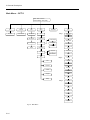
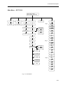
Main Menu – OPTI CCA
RUN: SRCs Controls
Data Time/Date Setup Diag
SRC
Controls
Data
Setup
Run SRC
Run Controls
Pat Reports
BP
SRC Reports
HbCal
Time/Date
Diag
Diag 1
Barometric
Pressure
Battery Voltage
Patient Report
Temperature
Control Reports
Print
# of Copies
Gas Pressure
Cal Report
Export
Vers
QC
Reports
Format
Barcode
Pat. Info
Diag 2
Printer
Optics
Misc
Password
LEDs
QC Lockout
RS232
Security
Units
IR
Fan
Correlation
FSET
Comm
Diag 3
Language
Gvalve
Flow
Disp
Battery
VDrive
Pump
Keypad
Fig. 2-11: Main Menu
2-21
2 General Description
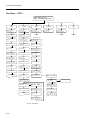
Sampling Menu – OPTI CCA
Power
On
AVL OPTI CCA
AOPX 2.0
Measuring - To input
xxx
Pat. Data press <ENTER>
Patient
Sample
Pat ID: XXXXXXXXXXX
AVL OPTI CCA
Please Wait
Patient Sample
Op ID: XXXXXXXXXXX
Please Wait
Warming up
Purging Gas System
Patient Sample
Temp: 37.0 C
xx
Measurement Completed
Warm Up
37.0 C
MENU <ENTER>
MCHC
200
pH PCO2
7.437 35.6
PO2
84.9
BE
1.5
READY-Swipe Cass.Barcode
For Menu press <ENTER>
Patient Sample
THb: 15.0 g/dL
NA
K+
156.7 5.23
tCO2p
20.7
Swipe Cassette
Barcode
PO2 tHb
SO2
147.4 15.4 95.6
Open cover - wipe and
insert Cass. - close cover
Calibrating
For READY press
Edit Pat. Data
xx
Hct(c)
46.2
Patient Sample
Sex: ? MALE FEMALE
Patient Sample
FIO2: 0.21
<ESC>
<ENTER>
Please Remove Cassette
Patient Sample
Hb Type: Adult Fetal
Patient Sample
P50: 26.7 mmHg
Please Wait
Checking Cassette
Patient Sample
RQ: 0.84
Aspirating Sample
Please wait.
Measuring Sample
Please wait
__________________
AVL OPTI CCA
Patient Report
Fig. 2-12: Sampling Menu
2-22
33.0%
2 General Description
Run Menu – OPTI CCA
RUN: SRC Controls
Data Time/Date Setup Diag
SRC
Controls
SRC Measurement
Op ID: XXXX
Data
Run Controls
Op ID: XXXXXXXX
Data: Patient
SRC Controls Export
Run Controls
Level: 1 2 3
Please Wait
To Data Menu
Open Cover - Insert SRC
Close Cover
Control Level x Lot#
To confirm
press<ENTER>
SRC Measurement
In Progress
Swipe Cassette Barcode
to run Control
SRC Level x Lot Number
Continue <ENTER>or
<ESC>
Open cover - Wipe and
insert cass.-close cover
SRC Measurement
in process
Calibrating
Please Wait
xx
pH PCO2 PO2 Test
7.100 70.0 60.1 Pass
Na+ K+ tHb Test
124.9 2.50 20.0 Pass
SO2
70.0
Test
Pass
Time: 08:51:23
Date: 15-Feb-95
Setup
Diag
Please enter PW2
Password <ENTER>
To Setup Menu
To Diag Menu
xx
Place Control
and press <ENTER>
xxx
Aspirating Control
Measuring Control
Please Open Cover
pH
PCO2 PO2 Test
7.238 45.3 101.8 Pass
Please Remove SRC
Na+
K+
167.4 8.61
Printed Results
Time/Date
Test
Pass
Please Open Cover and
Remove Cassette
Control Results:
Accept Rej/Edit
Review
Pass
Review
Please Remove Cassette
Printed Results
Rej/
Edit
Reject Results
<ESC>
Edit Level,ID
<ENTER>
ESC
ENTER
Run Controls
Op ID: XXXXXXXXXXX
Run Controls
Level: 1 2 3
Control Level x Lot#
To confirm press<ENTER>
Fig. 2-13: Run Menu
2-23
2 General Description
Data Menu – OPTI CCA
Data: Patient
SRC Controls Export
Data - Patient
Report: Last Last5
Data - SRC
Report: Last5 Statistic
Data - Controls
StatsReprt: ALL L1 L2 L3
Last: Displays and Prints last
patient result
Last 5: Prints last 5
SRC results
Data - Controls - Lx or ALL
Print Delete_Lx or _ALL
Last 5: Prints last 5
patient results
Data - SRC - Statistics
Print Delete_All
Print control data for particular
level or for all.
All: Prints all patient results in
memory
Please Enter PW2
Password <ENTER>
DATA - Controls - Lx or ALL
Delete Printed Data: N Y
SRC Database deleted
Please Enter PW2
Password <ENTER>
Print Statistics for all levels
Delete control data for particular
level or for all.
All
DATA - SRC
Delete All SRC Data: N Y
Fig. 2-14: Data Menu
2-24
Data - Export
Patient SRC
Controls
2 General Description
Setup Menu – OPTI CCA
Setup
Please enter PW2
Password <ENTER>
Setup: Baro HbCal Print
QC Format Pat.Info Misc.
SETUP - HbCal
AVL-Calibrator LastBlood
Barometer
SETUP - Please enter the
Baro: 727.3 mmHg
Print
Format
QC
Clean Optics and
inside of Cover
<ENTER>
SETUP - Print
Patient Report: OFF ON
SETUP-QC Swipe Barcode
or <ENTER> for menu
Please Open Cover
SETUP - Print
Number Copies: 1 2
SRC Level x
Lot No.: xxxxxx
Please Wipe and Insert
Calibrator; Close Cover
SETUP - Print
Cal.Report:
OFF ON
SRC Level x xxxxxx
Exp. Date: xxx-xx
Control Level x
Lot No: xxxx
SETUP - Patient Info
ON/OFF Defaults Limits
SETUP - ON/OFF
Patient ID: OFF ON
SETUP - Defaults
tHb: 15.0 g/dl
SETUP - Limits
pH: 7.350 - 7.450
SETUP - ON/OFF
PatID: Optional Required
SETUP - Defaults
FIO2: 0.21
SETUP - Limits
PCO2: 35.0 - 45.0
SETUP - ON/OFF
Operator ID: OFF ON
SETUP - Defaults
RQ: 0.84
SETUP - Limits
PO2: 80.0 - 100.0
SETUP - ON/OFF
OpID: Optional Required
SETUP - Defaults
P50: 26.7
1
Control Level x xxxx
Swipe Second Barcode
Now
Patient Info
Miscellaneous
SETUP - Format
Printout Display
SETUP - Format Print
xxx
: OFF ON
SETUP - QC
SRC Control
Control Level x xxxx
Exp. Date: xxx-xx
SETUP - Format Display
Show with ABG : BE
SETUP - SRC or Control
Level: 1 2 3
Control Level x xxxx
Type: OPTI-check
SETUP - Format Display
Show with Lytes : tCO2p
Control Level x xxxx
pH: 7.360 - 7.440
SETUP - Format Display
Show with Hb : Hct(c)
Control Level x xxxx
PCO2: 41.0 - 51.0 mmHg
Control Level x xxxx
PO2: 90.0 - 114.0 mmHg
SETUP - ON/OFF
Temp: OFF ON
Control Level x xxxx
Na: 138.0 - 147.0 mmol/L
SETUP - ON/OFF
tHb: OFF ON
Control Level x xxxx
K: 4.10 - 4.60 mmol/L
SETUP - ON/OFF
Sex: OFF ON
Control Level x xxxx
tHb: 11.7 - 14.6 g/dL
SETUP - ON/OF
FIO2: OFF ON
Control Level x xxxx
SO2: 86.0 - 94.0 %
SETUP - ON/OFF
Hb Type: OFF ON
SETUP - ON/OFF
P50: OFF ON
1
SETUP - ON/OFF
RQ: OFF ON
SETUP - Misc
Unit Corr Comm Lang Bat
Security
SETUP - Security
Password QC-LockOut
SETUP - Password
None PW1 PW2 PW1+2
SETUP - Password
Please Enter PW: XXXXX
SETUP - QC-Lockout
None SRC NewLot Both
SETUP - Units
Units: Conventional SI
SETUP - Correl. Factors
xxx Slope: 1.00
SETUP - Comm
Format Auto-Export
SETUP - Units
Temp: C F
SETUP - Correl. Factors
xxx Offset: 0.000 + -
SETUP - Comm - Format1
RS232 IR
SETUP - Units
Time: 12 hr 24 hr
SETUP - Language
Engl Deut Japn Fran Espa
SETUP - Battery Saver
AutoOff: 60 10 AlwaysOn
SETUP - Display Light
AutoOff AlwaysOn
SETUP - Comm - Format2
ASCII ASTM Mobile-ASTM
SETUP - Units
tHb: g/dL g/L mmol/L
SETUP - Units
Resolution: Low High
Fig. 2-15: Setup Menu
2-25
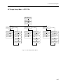
2 General Description
Diagnostic Menu – OPTI CCA
RUN: SRC Controls
Data TimeDate Setup Diag
DIAG1:Baro Batt Temp Gas
Vers Reports BCode DIAG2
DIAG2: Printr Optics LEDs
RS232 IR Fan FSET DIAG3
DIAG3: GValve Flow Disp
VDrive Pump keypad DIAG1
DIAG1: - Barometer
Baro: 731.9 mmHg
DIAG2: - Printer Test
DIAG3: - Valve
Valve: ON OFF
DIAG1: - Battery
Battery Voltage: 12.9 V
DIAG2: - Test Optics
DIAG3: - Flow Test
Insert Cassette
<ENTER>
DIAG1: - Temp. T3:31.48
T1:37.31
T2:37.01
DIAG2: - Optics Test
Insert SRC
<Enter>
DIAG3: - Flow Test
Test in Process ......
DIAG2: - Optics Test
Test in Process ..
DIAG1: - Flow
Pass:
DIAG1: - Gas
Gas Pressure: High
DIAG1: - Gas
Purge <ENTER> or <ESC>
4.54 5.70
<ENTER>
DIAG2: - Optics Test
Remove SRC
DIAG1: - Flow Test
Discard Cassette
DIAG1: - Version
Version: AOPX2.0
DIAG2: - LEDs LT1:0 LT2:0
L1: 2614 L2: 2988 CD: 519
DIAG2: - Display Test
DIAG1: - Version
Optics: OPTIC2H
DIAG2: - Interface
RS232-Jumper2-3 <ENTER>
DIAG3: - VDrive
Position: 0
DIAG2: - IR
IR Loopback Test: PASS
DIAG3: - Pump
Pump Speed: 800
DIAG2: - Fan
Cooling Fan: Off On
DIAG2: - Keypad
Key:
DIAG1: - Report
Errors Cals SRCs Config
Error Report
Password
<ENTER>
SRC Report
Configuration Report
Calibration Report
DIAG1: - Barcode
Barcode:
DIAG1: - Cleaning
Remove PumpCart<ENTER>
DIAG1: - Cleaning
Place Syringe
<ENTER>
DIAG1: - Cleaning
Perform Wash
<ENTER>
DIAG1: - Cleaning
Reinsert Pump
<ENTER>
Fig. 2-16: Diagnostic Menu
2-26
xxx
2 General Description
QC Range Setup Menu – OPTI CCA
Data - Controls
Ranges Statistics Type
Please Enter PW2
Password <ENTER>
Data - Control Ranges
Control Level: 1 2 3
Control Level 1 xxxxxx
Change Lot #: N / Y
Yes
No
Control Level 2 xxxxxx
Change Lot #: N / Y
Yes
No
Control Level 3 xxxxxx
Change Lot #: N / Y
Yes
No
Control Level 1 xxxxxx
pH: 6.900 - 7.700
Control Level 1 xxxxxx
Print Old Data: N / Y
Control Level 2 xxxxxx
pH: 6.900 - 7.700
Control Level 2 xxxxxx
Print Old Data: N / Y
Control Level 3 xxxxxx
pH: 6.900 - 7.700
Control Level 3 xxxxxx
Print Old Data: N / Y
Control Level 1 xxxxxx
PCO2: 10.0 - 120.0
Control Level 1 xxxxxx
Delete Old Data: N / Y
Control Level 2 xxxxxx
PCO2: 10.0 - 120.0
Control Level 2 xxxxxx
Delete Old Data: N / Y
Control Level 3 xxxxxx
PCO2: 10.0 - 120.0
Control Level 3 xxxxxx
Delete Old Data: N / Y
Control Level 1 xxxxxx
PO2: 20.0 - 500.0
Control Database
Deleted
Control Level 2 xxxxxx
PO2: 20.0 - 500.0
Control Database
Deleted
Control Level 3 xxxxxx
PO2: 20.0 - 500.0
Control Database
Deleted
Control Level 1 xxxxxx
New Lot No: 111111
Control Level 2 xxxxxx
New Lot No: 222222
Control Level 3 xxxxxx
New Lot No: 333333
Control Level 1 xxxxxx
Exp. Date: 31-Dec-95
Control Level 2 xxxxxx
Exp. Date: 31-Dec-95
Control Level 3 xxxxxx
Exp. Date: 31-Dec-95
Fig. 2-17: QC-Range Setup Menu
2-27
3 Installation and Maintenance
3 Installation and Maintenance
OPTI 1 System
Environment
Location is important for trouble-free operation of your analyzer. Before beginning
setup of the analyzer, choose a location that provides a stable flat surface and meets
the following environmental requirements for the unit:
•
Grounded electrical outlet if operated with optional power supply.
•
Away from direct sunlight.
•
Room temperature between 15 ºC and 32 ºC (59 - 90 °F).
•
Maximum relative humidity of 95% non-condensing.
•
Sufficient space to allow air to circulate around the unit.
•
Away from strong electromagnetic fields, such as those created by electric
motors and X-ray equipment.
•
Away from explosive gases or vapors.
•
Secure and level work surface.
Note: Above requirements also apply when the OPTI 1 Analyzer operates on
battery power outside a laboratory setting.
Before beginning installation of the analyzer, check the contents to ensure that the
required accessories have been included and are free from shipping damage. Check for
these items which are necessary to complete the installation of the OPTI 1 system:
•
Power Cord
•
2 Standard Reference Cassettes (SRC)
•
Battery Pack
•
Power Supply (Battery Charger)
•
OPTI 1 Cassette Packs
•
Thermal Printer Paper
•
Blood Gas Controls
•
Peristaltic Pump Cartridge
•
Gas Cylinder
•
Capillary Tubes
3-1
3 Installation and Maintenance
Analyzer Installation
Begin by placing the analyzer on a secure table top that allows sufficient work space and is
near an electrical power outlet.
1. Plug in the Battery Charger
•
•
Plug the battery charger power cord into the receptacle on the left rear side of the
analyzer.
Plug the power cord into a grounded electrical outlet.
2. Install the battery pack in the battery receptacle
•
Push the battery pack into the receptacle on the left hand side of the OPTI 1.
Note: The battery will need to be charged for at least 6 hours prior to use without the
AC Adapter. It will be charged automatically whenever the analyzer is plugged
into an electrical outlet.
3. Turn on the Power
•
Locate and turn on the power switch on the left side of the analyzer.
The AVL OPTI 1 Analyzer will now begin warming up. During this time keypad
entries can be made to configure the analyzer settings.
•
•
•
•
Use the numeric keys to make changes to the information on the display.
Use the J key to accept the displayed values or information.
The arrow keys, l and r are used to move the cursor and select menus.
The E key returns you to the previous software level.
4. Install the Gas Cylinder
•
•
•
•
Remove the protective cap on the gas cylinder.
Swipe the barcode of the gas bottle.
Insert the cylinder into the gas receptacle located on the right hand side of the analyzer.
Turn clockwise (to the right) until ‘finger’ tight. Be sure the tank fits tightly to avoid
any gas leaks.
Note:
3-2
A wrench is not needed to tighten the gas cylinder. The low pressure seal is
made with an O-ring.
3 Installation and Maintenance
5. Install the Printer Paper
•
Place paper into the paper tray.
•
•
Thread the paper into the paper feed slot, as shown in the diagram on the analyzer.
Press the paper advance button to bring the paper completely through the feeder.
6. Enter Date and Time
•
•
•
Move the cursor to the correct position (with arrow key).
Enter correct date, press J.
Follow the same procedure to enter the correct time, then use the arrow key to make AM or
PM blinking, press J
Note: The Date and Time need only be entered when the system is installed.
The system purges the gas system for approximately one minute.
The system will complete its warm-up.
Once the warm-up is complete, the analyzer is ready for sample analysis.
Prior to analyzing patient samples or Quality Control materials, a complete check should be performed.
In addition, run the Standard Reference Cassettes (SRC’s) to validate system performance. Refer to
Chapter 4, Sec 4.5.1 “Running an SRC Measurement” of the Operator’s Manual for instructions.
3-3
3 Installation and Maintenance
Maintenance
The OPTI 1 analyzer requires minimal routine operator maintenance to provide
trouble-free operation. The routine maintenance required is described in this section.
Daily Maintenance
No daily maintenance is required for the OPTI 1 analyzer.
Weekly Maintenance
Once per week, the Sample Measurement Chamber (SMC) must be cleaned. Open the
top cover and clean the optics surfaces with a lint-free cloth, slightly moistened with a
dilute alcohol or ammonia-based cleaner as needed. Make sure to remove any blood
residue. Use a cotton swab for cleaning cramped or restricted areas such as near the
valve drive.
Annual Maintenance
Once a year, the peristaltic pump cartridge needs to be replaced.
As Needed Maintenance
The gas cylinder is designed to provide up to 200 sample measurements. The analyzer
provides a display message to inform the user when it is necessary to change the gas
cylinder.
The thermal printer paper supplied with the OPTI 1 includes an indicator strip to alert
the user when the paper roll needs to be replaced.
Clean the outside housing surfaces of the OPTI 1 using a soft damp cloth as necessary
to preserve the appearance of the analyzer.
Note:
3-4
Never use strong chemical or abrasive cleaners on the OPTI 1 to avoid
damage to the housing surfaces.
4 Mechanics
4 Mechanics
OPTI System
The AVL OPTI is completely housed in a molded plastic case, which provides a
chassis for the electronic and mechanical assemblies. The analyzer is designed for
quick removal of all major assemblies. Some of the components such as the printer,
pump cartridge and top plate are accessible from the outside of the analyzer. The
analyzer interior is accessible, after removing the bottom of the analyzer. The
following chapter describes the removal of the major assemblies of the OPTI analyzer.
Caution: Before disconnecting any analyzer assemblies, disconnect the analyzer from
primary power and remove the installed battery to avoid electrical damage
or electrical shock.
Pump Cartridge
The pump cartridge can be removed easily. Open the printer compartment cover to
access the pump cartridge. Grasp the pump cartridge and pull straight up to free it
from the pump motor shaft.
To reinstall the pump cartridge, first check whether the flat in the pump spool is
aligned with the flat on the pump motor shaft. If the flat on the pump spool is not
aligned, a coin can be used to turn the spool within the pump cartridge housing and
align the pump spool with the motor shaft. The motor shaft may also be turned for
easier reinstallation of the pump cartridge. For easiest alignment of the motor shaft,
turn the motor shaft so the flat on the motor shaft is parallel to the right side of the
analyzer housing with motor shaft flat to the right. Insert the pump cartridge and press
down with a slight force so the cartridge fits onto the motor shaft and ensure the
cartridge is seated into the pump ports. Press down on the pump spool to prevent the
pump roller from binding on the pump cartridge housing.
Printer Assembly
To remove the printer assembly, first open the printer cover to gain access to the
printer assembly. First remove the pump cartridge to allow enough free space for
removing the printer assembly without interference in the printer compartment. The
pump cartridge can be removed by grasping it and pulling it up. Next remove the
printer paper and set aside. Two thumbscrews that hold the printer assembly in place
can now be loosened. After the thumbscrews have been loosened, the printer can be
slid towards the rear of the analyzer. Disconnect the printer ribbon cable that attaches
to the printer. The printer assembly can now be removed.
4-1
4 Mechanics
Analyzer Housing
The main analyzer housing is comprised of two parts, the lower and upper housing.
The assemblies located inside the analyzer can be removed. To gain access to these
assemblies, the analyzer housings must be separated. To open the analyzer housing,
first remove the battery on the left side of the analyzer. Turn the analyzer over to
access the seven (7) screws securing the two housing sections together. Remove the
screws and separate the upper and lower housing sections.
Caution: When turning the analyzer over to access the lower housing section, place
the analyzer on a padded surface to prevent scratches or other damage to
the upper housing section.
Sample Measurement Chamber Cover
To remove the SMC cover, the bottom of the analyzer must first be opened to separate
the top and bottom portions of the analyzer housing. Locate the cable and disconnect
the cable from the main board. Open the top cover of the SMC and remove the two (2)
screws at the cover hinge. Next remove the hinge plate. Then pull the cover to
remove it. The cable will be attached to the SMC cover. For reinstallation follow the
above steps in reverse order.
Note: The OPTI CCA SMC Cover is not field replaceable. The complete unit must
be returned the local service repair facility.
SMC Lower Module
The SMC top cover must first be removed. Disconnect the cables for the valve drive
motor, sample light gates and optics. Next remove the tygon tubing from the
peristaltic pump port. For easier access, remove the battery housing and the gas
module. Three (3) screws hold the module in place. Pull out the module from the
bottom of the analyzer. For reinstallation follow the above steps in reverse order.
Spare SMC modules are delivered with a calibration sheet. Upon installation of the
new SMC module, the values indicated on the calibration sheet have to be programmed
into the instrument using the Fset menu (see Chapter 6 - Fset).
4-2
4 Mechanics
OPTI Handle
The OPTI is equipped with a carrying handle for easy transport. To remove the
handle, first separate the lower portion of the analyzer. To access the handle, remove
the battery compartment, gas manifold module and storage compartment. Next remove
the four (4) self-tapping screws which hold the handle in place.
Gas Manifold Module
The gas manifold module is located on the right rear side of the analyzer. The
calibration gas cylinder is screwed into the module to form a gas-tight seal. The gas
manifold module provides pressure regulation and controls the flow of gas when
required for cassette calibration. To remove the module, first open the lower portion
of the analyzer. Disconnect the tygon tubes, which connect to the peristaltic pump and
clean-out port. Next disconnect the cable connector on the Main Board. There are two
(2) retaining screws that hold the module in place. After removal of these screws, the
module may be pulled out of the analyzer. Upon reassembly, make sure the tubes from
the clean-out port and the peristaltic pump are connected to the correct nipples. The
tubes should not be crossed.
There are two types of gas manifolds. The older type is marked with a red dot, the
newer type with a green dot (do not confuse the dot with the calibration label which is
white or green and contains a 3-digit number). After installation, the correct type - red
or green - must be programmed into the instrument, using the Fset menu (see Chapter
6 Fset).
Display Assembly
The OPTI uses a backlit LCD display module to display operating instructions and
analyzer results. To remove the LCD display, first open the lower portion of the
analyzer and disconnect the ribbon cable on the main board. The storage compartment
and gas manifold module must also be removed. Next remove the four (4) screws
which hold the LCD display assembly in place. The assembly can now be removed.
To reinstall the assembly, follow the removal instructions in reverse order. Before
tightening the mounting screws, make sure to center the display over the window.
4-3
4 Mechanics
Keypad
The keypad fitted on the OPTI can be removed by first opening the lower portion of
the analyzer. The flex cable from the keypad will now need to be disconnected from
the display board. Use a knife to lift off the keypad from the analyzer housing. Before
replacement with a new keypad, the surface must be cleaned. Use alcohol to remove
any adhesive, which may be on the surface. The surface must be clean and dry before
installing a new keypad. Take the new replacement keypad and remove the backing to
expose the adhesive side of the keypad. Carefully apply the new keypad to ensure
proper alignment on the analyzer housing.
Caution: The keypad is attached to the housing of the analyzer with an adhesive
backing and can not be re-used once removed from the analyzer.
Exhaust Fan
The OPTI is equipped with an internal exhaust fan, which is used for cooling the
electronic circuitry. To remove the fan, first open the lower portion of the analyzer.
Disconnect connector that attaches to the main board. One (1) screw fastens to the fan
retainer and must be removed. Next remove the retainer and slide the fan out of the
analyzer.
The software controls the fan. T3 measures the air temperature inside the OPTI
housing and is displayed in the DIAG1 - Temp menu. If T3 rises above 31.5 ° C, the
fan is activated. The fan turns off, when T3 drops below 30.5 ° C.
Storage Compartment
Located on the rear panel of the OPTI is a storage compartment. The storage
compartment is included to provide a convenient location for storing small accessories
during transport of the analyzer. To disassemble the storage compartment, first
separate the lower portion of the analyzer. Then, slide the storage compartment out of
the upper housing. To replace the storage compartment, fit the grooved edges of the
compartment over the upper housing and slide it into place.
Peristaltic Pump Motor
The peristaltic pump assembly is comprised of the pump motor and the peristaltic
pump cartridge and during operation provides the necessary pump flow to move
reagents and samples into the OPTI. The peristaltic pump uses a stepper motor, which
is controlled by the main board and turns the pump roller in the pump cartridge to
generate a small vacuum. To remove the pump motor, open the lower portion of the
analyzer housing for access to the assembly. Remove the pump cartridge and
disconnect the pump motor cable from the main board. Locate the pump motor and
remove the four (4) mounting screws. The motor may now be removed. For
reinstallation, reverse above steps.
4-4
4 Mechanics
Battery Receptacle
The OPTI can be operated by either battery power or by connection to a supplied
battery charger unit connected to AC main power. The battery can easily be
exchanged with a fully charged battery as described in the Operator’s Manual. To
remove the battery receptacle, first remove the battery from the analyzer. The lower
housing portion of the analyzer must be opened for access. Locate the battery
receptacle and disconnect the internal cable from the main board. Next remove the
two (2) retaining screws and pull the receptacle out of the analyzer.
Main Board Assembly
The OPTI analyzer is controlled and powered by the main board assembly. This board
contains the microprocessor and associated control circuitry. Interconnections for the
major assemblies are by cables attached directly to the board. For board removal first
open the lower portion of the analyzer housing to access the board. Disconnect all the
cables attached to the board. Remove the two (2) retaining screws that secure the
board to the lower portion of the analyzer housing and pull out the circuit board.
Located on the back of the main board are two (2) EPROM’s which can also be
replaced in the event of failure or software revision. It is not necessary to separate the
analyzer housing to access these EPROM’s. The OPTI analyzer has been designed and
is equipped with an EPROM cover located on the bottom of the analyzer. Remove the
cover to access the EPROM’s. A special EPROM carrier can be used for easy
installation and removal of the EPROM’s. This special carrier allows for customer
replacement of the EPROM’s. To remove the EPROM’s after opening the EPROM
cover, insert a coin under the tabs of the carrier and pry out the EPROM’s.
Replacement EPROM’s are supplied with the EPROM carrier for easy installation.
Caution: Always disconnect power and remove the battery before handling electronic
assemblies. When replacing the main board, perform the adjustment
procedures outlined in Section 7 of this manual before returning to
operation.
To reset the OPTI software after installing new software or in the event of system
corruption, open the cover, hold in the paper advance button and cycle the main power.
Caution: When the OPTI software is reset, all patient results, QC data, SRC data and
setup parameters stored in system memory will be lost.
4-5
4 Mechanics
To replace the main board, separate the lower housing from the upper housing by
removing 7 screws. Next, disconnect all cables from the main board. For easy access,
place the OPTI upside down on a work surface. Then, flip the lower housing over the
handle. After all cables have been disconnected, remove the lower housing. Remove
the two screws that hold the main board in place and install the new board in reverse
order. The EEPROM on the main board holds all factory settings for the OPTI. To
avoid reprogramming all these values, install EEPROM from the old board onto the
new board. As an alternate method, record all Fset values (see Chapter 6 - Fset) prior
to removal of the old board and reprogram the values after installing the new board.
Note: The OPTI CCA Main Board is not field replaceable. The complete unit must
be returned the local service repair facility.
Barcode Reader
The internal barcode reader assembly is used to read the barcode data supplied with
each cassette and Standard Reference Cassette (SRC). To access the internal barcode
reader, first separate the upper and lower analyzer housing sections. Locate the
barcode reader guide. Push on the latch and slide the guide downward. The module is
held in place by retaining screws, which must be removed. Disconnect cable from the
main board. Pry out the window of the barcode reader with a screwdriver.
4-6
5 Electronic Description
5 Electronic Description
OPTI 1 Main Board
The AVL OPTI 1 Main Board consists of the following electronic circuits.
The schematic diagram for each part of the electronic description is located in Section
9 and is referenced to a sheet number corresponding to the electronic descriptions
found in this section.
SYSTEM FUNCTIONAL BLOCK DIAGRAM SHEET 1
CIRCUIT DIAGRAM SHEET 2
Component Location
CIRCUIT DIAGRAM SHEET 3
Real Time Clock
RAM Battery Back-up
Address Decoder
CIRCUIT DIAGRAM SHEET 4
Microprocessor
Clock
CIRCUIT DIAGRAM SHEET 5
16 Bit EPROM
CIRCUIT DIAGRAM SHEET 6
16 Bit RAM
CIRCUIT DIAGRAM SHEET 7
RS232 Controller
Barcode Controller
Buzzer
CIRCUIT DIAGRAM SHEET 8
Keypad Controller
Keypad Decoder
Parallel Display Register
CIRCUIT DIAGRAM SHEET 9
Status LED Driver
Cassette Detection
Motor Drive Detection
Gas Pressure Input
7 Stage Ripple Counter
CIRCUIT DIAGRAM SHEET 10
Input Power and Power Switch
Main Power Fuse F1
Battery Charge Controller
Battery Status LED
5-1
5 Electronic Description
OPTI 1 Main Board
Continued
CIRCUIT DIAGRAM SHEET 11
Fuses F2 and F3
Switching +5 Volt Regulator
+ 5 Volt Regulator
+ 12 Volt Regulator
Positive to Negative Voltage Converter
- 5 Volt Regulator
SSMC Heater Supply
CIRCUIT DIAGRAM SHEET 12
+5 Volt Reference Voltage Regulator
SSMC Temperature Controller
CIRCUIT DIAGRAM SHEET 13
SSMC Heater Drivers
CIRCUIT DIAGRAM SHEET 14
SMC Bottom Plate NTC
SMC Top Plate NTC
Battery Back-up Reference
CIRCUIT DIAGRAM SHEET 15
Sample Sensor LED D/A Controllers
Barometric Pressure Reference Voltage
CIRCUIT DIAGRAM SHEET 16
A/D Converter
CIRCUIT DIAGRAM SHEET 17
Barometric Pressure Converter
CIRCUIT DIAGRAM SHEET 18
Peristaltic Pump Controller Driver
Valve Drive Motor Driver
Gas Valve Driver
CIRCUIT DIAGRAM SHEET 19
Printer Motor Controller Driver
Printer Serial to Parallel Converter
CIRCUIT DIAGRAM SHEET 20
Cassette Detection
CIRCUIT DIAGRAM SHEET 21
Connectors to Assemblies
5-2
5 Electronic Description
Main Board Circuit Diagram
Sheet 1
The Main Board circuitry is divided into 20 separate circuit schematic diagrams.
The division of the circuit schematic is done to facilitate component identification and
signal tracing. Each diagram contains signal labels allowing service personnel to trace
signals throughout the board. Located near the signal labels are small case numbers.
These numbers identify the circuit sheet where the signal is connected.
Main Board Circuit Diagram
Sheet 2
This diagram shows the component location on the main board.
Main Board Circuit Diagram
Sheet 3
IC U41, a non-volatile controller, detects analyzer power supplied either by the
internal battery system or the external power source. In the event of a loss of power,
U41 switches to provide RAM battery backup from battery BT1.
IC U38 is a real-time clock and provides time and date information used within the
AVL OPTI 1. Crystal Y3 is connected to IC U38 to provide a constant operating
frequency and control of the real-time clock.
IC U19 and U13 are 2 of 8 decoders providing various signal outputs as labeled on the
right side of the schematic diagram. These two decoders utilize signals PCS0 through
PCS3 as a control signal to decode 14 outputs, as two outputs are not used.
Main Board Circuit Diagram
Sheet 4
A 132 pin MOTOROLA MC68372 microprocessor, U24, controls the AVL OPTI 1.
Crystal Y2 is connected directly to the microprocessor to provide a stable frequency
control to the microprocessor. U54B, a quad gate is also connected to the crystal and
is used as a buffer to provide a 32KHz signal to other portions of the electronic
circuitry. U30 is an in-line buffer used to buffer some of the microprocessor inputs.
5-3
5 Electronic Description
Main Board Circuit Diagram
Sheet 5
U9 and U10 are 512K by 8 EPROMS and together comprise a 16-bit data bus used by
the OPTI 1. The user fits these two EPROMS to the main board in a special socket,
which allows for easy removal of the EPROMS to allow software replacement.
U8 is a serial 128 by 16 Serial EEPROM that stores instrument specific data.
Main Board Circuit Diagram
Sheet 6
The circuitry on this sheet, IC’s U7 and U11 are 128K by 8 RAM chips that together
provide a 16 bit data byte.
Main Board Circuit Diagram
Sheet 7
IC U3 is a Dual RS232 Driver and provides the serial interface control within the OPTI
1. Connected to U3 and mounted to the Main Board is P1, a standard 9-pin D-type
connector.
U5 is a barcode controller. The barcode controller is connected to the internal barcode
reader through J14 and an optional external barcode wand which can be connected
through J2, a RJ45 type connector mounted on the main board. The barcode input
from either barcode device is fed to pin 8 of U5 and an 8-bit data output is buffered by
U6.
BZ1 driven by transistor Q8 is a piezo speaker and provides an audible alarm when
activated.
5-4
5 Electronic Description
Main Board Circuit Diagram
Sheet 8
Plug J13 provides input from the Keypad and is fed to U49, an 8 bit serial input latch,
which decodes the selected keypad entries. The serial output is buffered and fed
directly to the microprocessor. U40A and U40B are dual D Flip-Flops, which provide
input to U51, one of eight decoders. U51 is fed to U49 to determine the correct
keypad row. U48A, B, C are part of a quad AND Gate package and provide debounce
circuitry for the keypad.
Serial data from the microprocessor is fed to the input of U50, a serial 8-bit shift
register to convert the serial display data to parallel data. The parallel data is
connected to the display through J13.
Main Board Circuit Diagram
Sheet 9
Serial data from the microprocessor is fed to U53, an 8-bit serial to parallel shift
register. This data provides the logic to control cassette detection LED’s and provides
output signals to the status LED. U44 is a seven-stage ripple counter used to divide the
32 kHz clock to a frequency of 1024 Hz. This divided clock and data from U53 are fed
to AND Gate U54A. This output provides the signal to drive the cassette light gates.
U52 is a parallel load to serial 8-bit shift register, which receives input from the
cassette light gates and other signals and provides serial data to the microprocessor.
Main Board Circuit Diagram
Sheet 10
Switch S1 is the main power switch and switches power to the OPTI 1 circuitry. Relay
K1 is used to switch input power either from the internal battery or main external
power supply. K2 is shown in the battery mode. When input power is supplied by the
external power supply, fuse F1 provides overcurrent protection for the input power.
U1 is a +5 Volt voltage regulator used to provide a regulated voltage supply to operate
U2. IC U2 is a battery charge controller with LED D46 indicating the battery charge
status. When D46 is solidly on, the battery is being charged and as the battery is fully
charged, D46 will blink rapidly to indicate the charge status. If D46 blinks slowly, it
indicates a defective battery or the battery temperature range has been exceeded.
A thermistor is included in the internal battery pack to provide temperature input to the
battery charge controller.
5-5
5 Electronic Description
Main Board Circuit Diagram
Sheet 11
Switched power, either from the external power supply or internal battery is fed to this
circuit and is fused by F2 and F3. The +12 or +16 volts (battery/external power
supply) is fed to Q4, a Darlington Pair, which provides supply voltage used to heat the
sample measurement chamber (SMC). This input voltage is also fed to U12 a
switching 5-Volt regulator, which supplies +5 volt power to the digital circuitry (ssv)
and printer (pvcc).
U14 is a +12V voltage regulator and feeds U20, a positive to negative voltage
converter. The negative voltage output from U20 is fed to U25 to provide a regulated 5 volt output. An additional +5V voltage regulator U21 is also used.
Main Board Circuit Diagram
Sheet 12
The SMC temperature circuitry comprises two temperature control circuits that control
the top plate heater and the optics module heater (lower plate). U26, a +5 volt
regulator, provides a reference voltage used by both circuits. Operational amplifier
U33D along with potentiometer R97 and R95 provide adjustment and control for both
heater circuits. IC U32A and U32B provide the optic module heater control while
U32C and U32D control the top plate heater.
Main Board Circuit Diagram
Sheet 13
This circuitry with inputs from sheet 11 controls the heater transistors in the SMC
assembly. U34D and U43C are connected to the base and emitter of the optics module
heater transistors. The signal OPTICCTRL (from sheet 11) causes the optics module
heater transistors to conduct more when the temperature of the optics module needs to
be increased to maintain regulation. IC U43A operates similarly as U34D and is
connected to the top plate heater transistor.
5-6
5 Electronic Description
Main Board Circuit Diagram
Sheet 14
This circuit converts resistance provided by the NTC’s to a voltage for the temperature
control of the top and bottom plate heaters located in the SMC. Op Amp U33A is fed
an input from the NTC located in the optics module heater (bottom plate), an output
voltage representative of the input NTC resistance. U33C is an identical circuit and
receives the NTC input from the top plate NTC. U33B is fed the reference voltage
input and provides the battery backup reference voltage (signal BCHRG2) which is fed
to the battery charge controller located on sheet 1.
Main Board Circuit Diagram
Sheet 15
The two digital to analog converters (DAC’s) U17 and U23 control the sample sensor
brightness or intensity for the sample sensor LED’s, LG1 and LG2 located in the SMC
assembly. A comparison is made with the values stored in memory and provides a
self-calibration. This signal is fed to each sample sensor anode, which controls the
intensity of the sample sensor LED’s. The reference voltage signal is fed to IC U22B,
which changes the impedance for the barometer circuit located on sheet 16.
Main Board Circuit Diagram
Sheet 16
The analog to digital converter U15 receives a parallel input of 8 analog signals and
converts these voltages to a serial digital signal which is fed directly to the
microprocessor via signal HIS0. The parallel input signals, which are labeled on the
schematic, can be observed on the analyzer display when the diagnostic menu is
selected.
5-7
5 Electronic Description
Main Board Circuit Diagram
Sheet 17
The internal barometer circuitry is comprised of the pressure transducer (BARO1) and
the associated circuitry. The output voltage of BARO1 changes according to the
changing atmospheric pressure. Op Amps U16 A, B, and C are used to calibrate the
output pressure and correlate this pressure to barometric pressure standard. The output
voltage at TP 15 represents barometric pressure in mmHg according to the following
formula:
Voltage + 3000 = BP mmHg
10
For calibration and adjustment use the procedure in Section 7, Adjustments.
Main Board Circuit Diagram
Sheet 18
The valves and stepper motors used in the OPTI 1 analyzer are controlled by the
circuitry contained on this schematic sheet. U47, a serial to parallel latch, receives
input from the microprocessor and provides the control signal for the gas valve along
with other signals as labeled. U28 is a serial to parallel decoder which decodes the
direction and enable signal for the valve drive, peristaltic pump and the printer. U36 is
the driver for the valve drive motor and is fed signals directly from the microprocessor
(TP0 - TP3) and an enable signal from U28 to provide four motor drive signals to
valve drive stepper motor. The peristaltic pump is controlled by U27, a stepper motor
controller, which feeds U35, the driver for the peristaltic pump stepper motor.
Main Board Circuit Diagram
Sheet 19
The internal printer is controlled by this circuitry. U45, a serial to parallel printer
driver, receives an enable signal and converts serial data from the microprocessor to a
parallel output which is fed to the printer print heads. The printer motor is controlled
and driven by U31 and U42. U31, the printer controller receives an enable and
direction signal which feeds U42, the motor driver for the printer stepper motor.
5-8
5 Electronic Description
Main Board Circuit Diagram
Sheet 20
The cassette detection infrared LED is monitored by U29 C and D and associated
circuitry. The signal from the cassette light gate is fed to U29D and further converted
by U29C. The resultant output is fed to the analog to digital converter on sheet 15
which indicates whether a cassette is in place.
Main Board Circuit Diagram
Sheet 21
This section of the main board circuitry provides signal identification for the
connectors and interconnection to the other assemblies within the OPTI 1 analyzer.
Also located on this schematic section is relay K2. Relay K2 is switched dependent on
whether full windings or half windings are required for the peristaltic pump motor.
5-9
5 Electronic Description
Main Board TEST Points
Test Point
TP1
TP2
TP3
TP4
TP5
TP6
TP7
TP8
TP9
TP10
TP11
TP12
TP13
TP14
TP15
TP16
TP17
TP18
TP19
TP20
TP21
TP22
TP23
TP24
TP25
TP26
TP27
TP28
5-10
Circuit
Sheet
10
10
10
11
10
10
17
17
15
11
11
11
16
16
17
11
17
15
11
16
16
12
12
18
12
12
12
10
Measurement
+5.00 ± 0.25 V
0.00 ± 0.02 V
N/A
+5.00 ± 0.2 V
N/A
N/A
-3.419 ± 0.020 V
+5.000 ± 0.005 V
N/A
N/A
N/A
N/A
N/A
N/A
Ref. Formula
+5.00 ± 0.20 V
N/A
N/A
-5.00 ± 0.20 V
N/A
N/A
+5.000 V ± .005 V
N/A
N/A
N/A
N/A
N/A
N/A
Description
Regulated + 5 Volt
Ground
Regulated + 5 Volt (VCC)
Barometer Reference Voltage
Precision Reference Voltage
SMC Heater Supply Voltage (VHTR)
Over Temperature
Unregulated Supply Voltage (VS)
Barometer Voltage Output
Regulated + 5 Volt (+5V)
Regulated - 5 Volt (-5V)
Precision +5 volt reference voltage
5 Electronic Description
Main Board
Connectors
J1
Pin
1
2
3
J2
Pin
1
2
3
4
5
6
7
8
J3
Pin
1
2
3
4
5
6
7
8
J4
Pin
1
2
3
4
Main Input Power
Signal Description
Positive Voltage from External
Power Supply/Charger
Ground
Sleeve (Ground)
Schematic Sheet Location
Sheet 10
Sheet 10
Sheet 10
External Barcode (RJ45)
Signal Description
NC
Shield (Connected to ground)
Ground
Supply Voltage
NC
NC
Schematic Sheet Location
Sheet 7
Sheet 7
Sheet 7
Sheet 7
Sheet 7
Sheet 7
Sheet 7
Sheet 7
Debug Connector
Signal Description
Not Used
Schematic Sheet Location
Sheet 4
Battery Connector
Signal Description
Battery Positive
NC
Battery Thermistor
Battery Negative
Schematic Sheet Location
Sheet 10
Sheet 10
Sheet 10
Sheet 10
5-11
5 Electronic Description
J5
Pin
1
2
3
4
5
6
7
8
9
10
11
12
13
14
15
16
17
18
19
20
5-12
Upgrade Board Connector
Signal Description
Ground
Ground
Ground
Supply Voltage
Ground
Ground
Supply Voltage
+5 Volts
-5 Volts
Ground
NC
NC
NC
NC
Schematic Sheet Location
Sheet 4
Sheet 4
Sheet 3, 4
Sheet 4
Sheet 4
Sheet 4
Sheet 4
Sheet 4
Sheet 3
Sheet 4
Sheet 3
Sheet 4
Sheet 4
Sheet 4
Sheet 4
Sheet 4
Sheet 4
Sheet 4
Sheet 4
Sheet 4
5 Electronic Description
J6
Pin
1
2
3
4
5
6
7
8
9
10
11
12
13
14
15
16
17
18
19
20
21
22
23
24
25
26
Printer Connector
Signal Description
Print Head 1
Print Head 2
Print Head 3
Print Head 4
Print Head 5
Print Head 6
Print Head 7
Print Head 8
Printer Supply Voltage PVcc
Printer Supply Voltage PVcc
Printer Supply Voltage PVcc
Printer Home Position
Ground
Motor Drive 4
Motor Drive 2
Motor Drive 1
Motor Drive 4
HRA
Supply Voltage Vcc
HRC
NC
NC
NC
Keyboard Row
NC
Keyboard Column
Schematic Sheet Location
Sheet 11
Sheet 11
Sheet 11
Sheet 11
Sheet 11
Sheet 11
Sheet 11
Sheet 11
Bus
Bus
Bus
Sheet 4
Sheet 11
Sheet 11
Sheet 11
Sheet 11
Sheet 11
Sheet 9
Bus
Sheet 9
Sheet 11
Sheet 11
Sheet 11
Sheet 8, 9
Sheet 11
Sheet 8
5-13
5 Electronic Description
J7
Pin
1
2
3
4
5
6
7
8
9
10
11
12
13
14
15
16
17
18
19
20
5-14
SMC Top Plate
Signal Description
Top Plate Heat Transistor
Emitter 1
Heater Supply Voltage
Top Plate Heat Transistor Base
Top Plate NTC 1
Top Plate NTC 2
Top Plate Heat Transistor
Emitter 2
NC
NC
NC
Heater Supply Voltage
Cassette Front Anode
Cassette Rear Anode
Cassette Front Collector
Cassette Rear Collector
Sense Rear Anode
Sense Front Anode
Sense Rear Collector
Sense Front Collector
Ground
Ground
Schematic Sheet Location
Sheet 13
Sheet 11
Sheet 13
Sheet 12, 14
Sheet 12
Sheet 13
Sheet 11
Sheet 9
Sheet 9
Sheet 9
Sheet 9
Sheet 15
Sheet 15
Sheet 15
Sheet 15
Ground Bus
Ground Bus
5 Electronic Description
J8
Pin
1
2
3
4
5
6
7
8
9
10
11
12
13
14
15
16
17
18
19
20
21
22
23
24
25
26
J9
Pin
1
2
3
4
5
6
Optic Module Connector
Signal Description
Supply Voltage Vcc
Reset
+5 Volts
- 5 Volts
Ground
Optics Transmit Data
Optics Receive Data
Ground
Ground
Optics Top Heater Transistor
Emitter 1
Heater Voltage Vhtr
Optics Top Heater Transistor
Base
Optics Top Heater Transistor
Emitter 2
Optics Block Heater Transistor
Emitter 1
Heater Voltage Vhtr
Optics Block Heater Transistor
Base
Optics Block Heater Transistor
Emitter 2
Optics Heater NTC 1
Optics Heater NTC 2
N/C
N/C
Cassette Light Gate Driver
Cassette Light Gate Collector
Sense Front Emitter
Sense Rear Emitter
Schematic Sheet Location
Bus
Sheet 4
Sheet 4
Bus
Bus
Bus
Sheet 7
Sheet 7
Bus
Bus
Sheet 13
Bus
Sheet 13
Sheet 13
Sheet 13
Bus
Sheet 13
Sheet 13
Sheet 12, 14
Sheet 12
Sheet 9
Sheet 20
Sheet 16
Sheet 16
Pump Motor Connector
Signal Description
Pump -D
Pump -C Relay K2
Pump -C
Pump -B
Pump -B Relay K2
Pump -A
Schematic Sheet Location
Sheet 18
Sheet 18
Sheet 18
Sheet 18
Sheet 18
Sheet 18
5-15
5 Electronic Description
J10
Pin
1
2
J11
Pin
1
2
3
4
5
J12
Pin
1
2
3
4
5
6
7
8
9
10
11
12
13
14
5-16
Fan Control Connector
Signal Description
+12 Volts
Fan Control
Schematic Sheet Location
Bus
Sheet 18
Gas Valve 1 Connector
Signal Description
Supply Voltage Vs
Gas Pressure 1
Gas Valve 1 (GV1)
Supply Voltage Vs
Auxiliary
Schematic Sheet Location
Bus
Sheet 9
Sheet 18
Bus
Sheet 18
Sample Measurement Chamber Connector
Signal Description
Ground
Ground
Home Position Light Gate
SMC Light Gate
Ground
Ground
Home Position LED
Supply Voltage Vvss
NC
NC
Valve -D
Valve -B
Valve -A
Valve -C
Schematic Sheet Location
Bus
Bus
Sheet 9
Sheet 9
Bus
Bus
Sheet 9
Bus
Sheet 18
Sheet 18
Sheet 18
Sheet 18
5 Electronic Description
J13
Pin
1
2
3
4
5
6
7
8
9
10
11
12
13
14
15
16
17
18
19
20
21
22
23
24
25
26
LCD / LED Connector
Signal Description
Keypad Row A
Keypad Column A
Keypad Row B
Keypad Column B
Keypad Row C
Keypad Column C
Keypad Row D
Keypad Column D
LCD BL
Status LED Green
Status LED Yellow
Status LED Red
Ground
Vcc
Status LED Blink
LCD Enable
LCD Read Write
LCD Reset
LCD Data 0
LCD Data 1
LCD Data 2
LCD Data 3
LCD Data 4
LCD Data 5
LCD Data 6
LCD Data 7
Schematic Sheet Location
Sheet 18
Sheet 9
Sheet 9
Sheet 9
Bus
Bus
Sheet 4
5-17
5 Electronic Description
OPTI CCA Circuits
The AVL OPTI CCA Optics Module and Main Board consist of the following
electronic circuits. The schematic diagram for each part of the electronic description is
located in Section 9 and is referenced to a sheet number corresponding to the
electronic descriptions found in this section.
SYSTEM FUNCTIONAL BLOCK DIAGRAM SHEET 1
CIRCUIT DIAGRAM
Component Location
CIRCUIT DIAGRAM SHEET 1
Optics Module
Digital Circuit
CIRCUIT DIAGRAM SHEET 2
Optics Module
Amplifier Circuit
CIRCUIT DIAGRAM SHEET 3
Optics Module
Amplifier Circuit
CIRCUIT DIAGRAM SHEET 4
Optics Module
Inverter Circuit
CIRCUIT DIAGRAM SHEET 5
Optics Module
A/D Converter Circuit
CIRCUIT DIAGRAM SHEET 6
Optics Module
LED’s, Gasses & DAC Circuit
CIRCUIT DIAGRAM SHEET 7
Optics Module
LED’s and Lytes Circuit
CIRCUIT DIAGRAM SHEET 8
Optics Module
Interconnect Circuit
5-18
5 Electronic Description
OPTI CCA Circuits
Continued
CIRCUIT DIAGRAM SHEET 1
Main Board
RAM Battery Backup Circuit
Clock Circuit
CIRCUIT DIAGRAM SHEET 2
Main Board
Microprocessor Circuit
CIRCUIT DIAGRAM SHEET 3
Main Board
16 Bit EPROM Circuit
CIRCUIT DIAGRAM SHEET 4
Main Board
16 Bit RAM Circuit
CIRCUIT DIAGRAM SHEET 5
Main Board
Barcode Interface Circuit
CIRCUIT DIAGRAM SHEET 6
Main Board
Keypad and Display Circuit
CIRCUIT DIAGRAM SHEET 7
Main Board
Cassette Detection Logic Circuit
CIRCUIT DIAGRAM SHEET 8
Main Board
Battery Charger Circuit
CIRCUIT DIAGRAM SHEET 9
Main Board
Voltage Regulator Circuit
CIRCUIT DIAGRAM SHEET 10
Main Board
SMC Temperature Control Circuit
5-19
5 Electronic Description
OPTI CCA Circuits
Continued
CIRCUIT DIAGRAM SHEET 11
Main Board
SMC Heater Transistor Circuit
CIRCUIT DIAGRAM SHEET 12
Main Board
SMC Heater Control Circuit
CIRCUIT DIAGRAM SHEET 13
Main Board
Digital to Analog Converter Circuit
CIRCUIT DIAGRAM SHEET 14
Main Board
A/D Converter Circuit
CIRCUIT DIAGRAM SHEET 15
Main Board
Barcode Circuit
CIRCUIT DIAGRAM SHEET 16
Main Board
Motor Drive Circuit
CIRCUIT DIAGRAM SHEET 17
Main Board
Printer Controller Circuit
CIRCUIT DIAGRAM SHEET 18
Main Board
Cassette Detect Circuit
CIRCUIT DIAGRAM SHEET 19
Main Board
Interconnect Circuit
CIRCUIT DIAGRAM SHEET 20
Main Board
Serial Interface Circuit
CIRCUIT DIAGRAM SHEET 21
Main Board
tHb/SO2 Laser/LED Driver Circuit
5-20
5 Electronic Description
OPTI CCA Circuits
Continued
CIRCUIT DIAGRAM SHEET 22
Main Board
tHb/SO2 Amplifier Circuit
CIRCUIT DIAGRAM SHEET 23
Main Board
Over Temperature Protection Circuit
CIRCUIT DIAGRAM SHEET 1
Optics Module
Interconnect Circuit
CIRCUIT DIAGRAM SHEET 2
Optics Module
LED’s, Gasses & Heater Circuit
CIRCUIT DIAGRAM SHEET 3
Optics Module
LED’s, ION & Heater Circuit
CIRCUIT DIAGRAM SHEET 1
Optics Module
SMC Heater / tHb Circuit
CIRCUIT DIAGRAM SHEET 1
Display IR Board
Interconnect Circuit
CIRCUIT DIAGRAM SHEET 2
Display IR Board
IR Circuit
5-21
5 Electronic Description
Main Board - OPTI CCA
TEST Points
Test Point
TP1
TP2
TP3
TP4
TP5
TP6
TP7
TP8
TP9
TP10
TP11
TP12
TP13
TP14
TP15
TP16
TP17
TP18
TP19
TP20
TP21
TP22
TP23
TP24
TP25
TP26
TP27
TP28
TP29
TP30
TP31
TP32
TP33
TP34
TP35
TP36
5-22
Circuit
Sheet
8
8
8
8
8
14
9
17
14
14
14
14
14
8
8
9
17
15
13
15
15
13
9
9
9
12
14
14
14
14
9
10
10
10
16
10
Measurement
+5.00 ± 0.25 V
N/A
N/A
N/A
N/A
N/A
+5.00 ± 0.2 V
+5.000 ± 0.005 V
N/A
N/A
N/A
N/A
N/A
N/A
N/A
N/A
N/A
-3.57 ± 0.020 V
N/A
Ref. Formula
N/A
N/A
N/A
N/A
+5.00 ± 0.20 V
N/A
N/A
N/A
N/A
N/A
-5.00 ± 0.20 V
+5.000 V ± .005 V
Description
Regulated + 5 Volt
Regulated + 5 Volt (VCC)
Precision Reference Voltage
SMC Heater Supply Voltage (VHTR)
Over Temperature
Unregulated Supply Voltage (VS)
Barometer Reference Voltage
Barometer Voltage Output
Regulated + 5 Volt (+5V)
Regulated - 5 Volt (-5V)
Precision +5 volt reference voltage
5 Electronic Description
Main Board - OPTI CCA
TEST Points
Test Point
TP37
TP38
TP39
TP40
TP41
TP42
TP43
TP44
TP45
TP46
TP47
TP48
TP49
TP50
Circuit
Sheet
9
8
10
21
21
21
21
21
21
21
23
23
22
22
Measurement
0.00 ± 0.02 V
Description
Ground
670 nm LED 670 nm LED +
850 nm Laser 850 nm Laser +
780 nm Laser 780 nm Laser +
5-23
5 Electronic Description
Main Board
Connectors
J1
Pin
9
10
11
12
13
14
15
16
J2
Pin
4
5
6
J3
Pin
5
6
7
8
5-24
External Barcode (RJ45)
Signal Description
NC
Shield (Connected to ground)
Ground
Supply Voltage
NC
NC
Schematic Sheet Location
Sheet 7
Sheet 7
Sheet 7
Sheet 7
Sheet 7
Sheet 7
Sheet 7
Sheet 7
Main Input Power
Signal Description
Positive Voltage from External
Power Supply/Charger
Ground
Sleeve (Ground)
Schematic Sheet Location
Sheet 10
Sheet 10
Sheet 10
Battery Connector
Signal Description
Battery Positive
NC
Battery Thermistor
Battery Negative
Schematic Sheet Location
Sheet 10
Sheet 10
Sheet 10
Sheet 10
5 Electronic Description
J4
Pin
1
2
J5
Pin
1
2
J6
Pin
21
22
23
24
25
26
27
28
29
30
31
32
33
34
35
36
37
38
39
40
tHb/SO2 Connector
Signal Description
Schematic Sheet Location
Sheet
Sheet
IRDA Connector
Signal Description
Schematic Sheet Location
Sheet
Sheet
SMC Top Plate
Signal Description
Top Plate Heat Transistor
Emitter 1
Heater Supply Voltage
Top Plate Heat Transistor Base
Top Plate NTC 1
Top Plate NTC 2
Top Plate Heat Transistor
Emitter 2
NC
NC
NC
Heater Supply Voltage
Cassette Front Anode
Cassette Rear Anode
Cassette Front Collector
Cassette Rear Collector
Sense Rear Anode
Sense Front Anode
Sense Rear Collector
Sense Front Collector
Ground
Ground
Schematic Sheet Location
Sheet 13
Sheet 11
Sheet 13
Sheet 12, 14
Sheet 12
Sheet 13
Sheet 11
Sheet 9
Sheet 9
Sheet 9
Sheet 9
Sheet 15
Sheet 15
Sheet 15
Sheet 15
Ground Bus
Ground Bus
5-25
5 Electronic Description
J7
Pin
7
8
9
10
11
12
J8
Pin
3
4
J9
Pin
6
7
8
9
10
J10
Pin
15
16
17
18
19
20
21
22
23
24
25
26
27
28
5-26
Pump Motor Connector
Signal Description
Pump -D
Pump -C Relay K2
Pump -C
Pump -B
Pump -B Relay K2
Pump -A
Schematic Sheet Location
Sheet 18
Sheet 18
Sheet 18
Sheet 18
Sheet 18
Sheet 18
Fan Control Connector
Signal Description
+12 Volts
Fan Control
Schematic Sheet Location
Bus
Sheet 18
Gas Valve 1 Connector
Signal Description
Supply Voltage Vs
Gas Pressure 1
Gas Valve 1 (GV1)
Supply Voltage Vs
Auxiliary
Schematic Sheet Location
Bus
Sheet 9
Sheet 18
Bus
Sheet 18
Sample Measurement Chamber Connector
Signal Description
Ground
Ground
Home Position Light Gate
SMC Light Gate
Ground
Ground
Home Position LED
Supply Voltage Vvss
NC
NC
Valve -D
Valve -B
Valve -A
Valve -C
Schematic Sheet Location
Bus
Bus
Sheet 9
Sheet 9
Bus
Bus
Sheet 9
Bus
Sheet 18
Sheet 18
Sheet 18
Sheet 18
5 Electronic Description
J11
Pin
27
28
29
30
31
32
33
34
35
36
37
38
39
40
41
42
43
44
45
46
47
48
49
50
51
52
Optic Module Connector
Signal Description
Supply Voltage Vcc
Reset
+5 Volts
- 5 Volts
Ground
Optics Transmit Data
Optics Receive Data
Ground
Ground
Optics Top Heater Transistor
Emitter 1
Heater Voltage Vhtr
Optics Top Heater Transistor
Base
Optics Top Heater Transistor
Emitter 2
Optics Block Heater Transistor
Emitter 1
Heater Voltage Vhtr
Optics Block Heater Transistor
Base
Optics Block Heater Transistor
Emitter 2
Optics Heater NTC 1
Optics Heater NTC 2
N/C
N/C
Cassette Light Gate Driver
Cassette Light Gate Collector
Sense Front Emitter
Sense Rear Emitter
Schematic Sheet Location
Bus
Sheet 4
Sheet 4
Bus
Bus
Bus
Sheet 7
Sheet 7
Bus
Bus
Sheet 13
Bus
Sheet 13
Sheet 13
Sheet 13
Bus
Sheet 13
Sheet 13
Sheet 12, 14
Sheet 12
Sheet 9
Sheet 20
Sheet 16
Sheet 16
5-27
5 Electronic Description
J12
Pin
27
28
29
30
31
32
33
34
35
36
37
38
39
40
41
42
43
44
45
46
47
48
49
50
51
52
5-28
Printer Connector
Signal Description
Print Head 1
Print Head 2
Print Head 3
Print Head 4
Print Head 5
Print Head 6
Print Head 7
Print Head 8
Printer Supply Voltage PVcc
Printer Supply Voltage PVcc
Printer Supply Voltage PVcc
Printer Home Position
Ground
Motor Drive 4
Motor Drive 2
Motor Drive 1
Motor Drive 4
HRA
Supply Voltage Vcc
HRC
NC
NC
NC
Keyboard Row
NC
Keyboard Column
Schematic Sheet Location
Sheet 11
Sheet 11
Sheet 11
Sheet 11
Sheet 11
Sheet 11
Sheet 11
Sheet 11
Bus
Bus
Bus
Sheet 4
Sheet 11
Sheet 11
Sheet 11
Sheet 11
Sheet 11
Sheet 9
Bus
Sheet 9
Sheet 11
Sheet 11
Sheet 11
Sheet 8, 9
Sheet 11
Sheet 8
5 Electronic Description
J13
Pin
27
28
29
30
31
32
33
34
35
36
37
38
39
40
41
42
43
44
45
46
47
48
49
50
51
52
LCD / LED Connector
Signal Description
Keypad Row A
Keypad Column A
Keypad Row B
Keypad Column B
Keypad Row C
Keypad Column C
Keypad Row D
Keypad Column D
LCD BL
Status LED Green
Status LED Yellow
Status LED Red
Ground
Vcc
Status LED Blink
LCD Enable
LCD Read Write
LCD Reset
LCD Data 0
LCD Data 1
LCD Data 2
LCD Data 3
LCD Data 4
LCD Data 5
LCD Data 6
LCD Data 7
Schematic Sheet Location
Sheet 18
Sheet 9
Sheet 9
Sheet 9
Bus
Bus
Sheet 4
5-29
6 Test Programs and Diagnostics
6 Test Programs and Diagnostics
OPTI 1 System
The AVL OPTI 1 is equipped with diagnostic routines designed to assist the user in
testing the operation of the each system component. These tests can be selected in the
Diagnostics Menu. An overview of the diagnostic tests available is located in Section
2. This section describes each diagnostic test and the expected result.
Diagnostic 1
Barometer
The BARO test displays the system barometric pressure in a real-time mode. This test
can be used to verify the internal pressure transducer is measuring correctly. The
barometric pressure should be compared to the laboratory reference standard and
calibrated accordingly. The operator can adjust the barometric pressure by entering
the correct value in the SETUP - BARO menu. To calibrate the internal barometer
follow the adjustment procedure outlined in Chapter 7.
Battery
The OPTI 1 may be powered by an internal battery pack or by an external battery
charger, which is supplied with the analyzer. This test allows the user to determine the
voltage of either the battery or external battery charger. When the charger is plugged
in and connected to the analyzer, the display indicates the battery charger voltage.
When the analyzer is powered from the internal battery, the displayed voltage is the
battery voltage. When the internal battery powers the OPTI 1, the voltage must be
greater than 11.2 volts for correct operation. While the external battery charger is
connected, the internal battery is being charged. The main board contains the required
circuitry to monitor and control the battery charging system. An LED is visible
through the rear cover indicating battery charge status. A solid ON light indicates the
battery is charging, while a fast flashing light (4 times per second) indicates the battery
is fully charged. The battery LED will be OFF when the analyzer is not connected to
the external charger. A slowly blinking light (once per second) indicates a very cold,
very hot or defective battery.
6-1
6 Test Programs and Diagnostics
Temperature
The temperature diagnostic test displays three system-operating temperatures. T1
displays the SMC top plate temperature, T2 displays the SMC lower plate temperature
and T3 displays the ambient temperature of the internal chassis and is used for the fan
control. Circuitry on the main board, optics module, and SMC heater board provides
temperature control for the analyzer. The following specifications are required for
proper operation:
T1 = 37.00° C ±0.05° C
T2 = 37.15° C ±0.05° C
T3 = Internal analyzer temperature
Adjustment of the temperature circuitry is described in Chapter 7, Adjustments.
Gas Pressure
The newly installed calibration gas cylinder contains a gas pressure of 140-psi (9.7
bar) and is regulated and monitored by the gas module assembly. The gas pressure
sensor portion of the module provides gas pressure status to the OPTI 1 analyzer. If
the gas bottle pressure falls below approx. 35 psi, the switch closes (low pressure).
The pressure needs to be above approx. 50 psi for the switch to open (high pressure).
This diagnostic test indicates HIGH PRESSURE or LOW PRESSURE depending on
the remaining gas cylinder pressure. When this diagnostic test is completed, an
additional screen is displayed to allow replacement of the gas bottle and a gas purge
sequence to be initiated by the user.
Cleaning
The OPTI 1 provides an automated cleaning routine that can be performed by selecting
the diagnostic cleaning menu. Operator instructions are displayed to provide the user
with a step-by-step guide for completion of the cleaning routine. First, the operator
will be instructed to remove the peristaltic pump cartridge followed by pressing J.
Next the operator will be instructed to place a syringe in the front peristaltic pump
receptacle. The syringe should contain a mild cleaning solution such as a 30% bleach
solution. Press J upon completion. The OPTI 1 will now instruct the operator to
perform a wash. To do this, move the cleaning solution back and forth to flush the
fluidic tubing. A tissue should also be placed at the inlet port of the SMC to catch any
cleaning solution, which may be pushed, through the port. Press J upon completion.
The operator will now be instructed to reinsert the pump cartridge. Press J to
confirm this action and complete the cleaning procedure.
6-2
6 Test Programs and Diagnostics
Flow
Performing a flow test requires the use of a new cassette. The purpose of the flow test
is to check proper operation of the pump, gas module and to detect leaks downstream
from the pump.
At the end of the flow test, a pass/fail as well as two flow numbers are displayed. If
the flow numbers are 99.99, this part of the test failed and no number could be
obtained.
Press J to start the test. First, the gas pressure is turned on (tubing upstream from
pump is pressurized). With the pump stopped, the fluid light gates L1 and L2 check
for the buffer to remain in the cassette. If the buffer is pushed out, the test fails and the
pump cartridge needs to be replaced.
Now the pump starts pumping slowly, while L2 is looking for the trailing edge of the
buffer. If the trailing edge is not detected within a certain time-out, the test fails.
Check for leaks downstream from the pump. Replace the SMC gas seal and the pump
cartridge receptacles.
Once L2 has detected the trailing edge, L1 is looking for the trailing edge of the buffer.
L1 must detect the trailing edge between 1.2 seconds and 5.2 seconds. The actual time
is indicated by the first number on the display at the end of the test. If the number is
less than 1.2 seconds, replace the gas bottle and check the output pressure of the gas
module (2.5 psi ± 0.5 psi).
Next, the system reverses the pump direction and measures the time of the buffer
movement between LG1 and LG2. Since now the pump transports the buffer against
the gas pressure, the time needs to be between 4.0 seconds and 8.0 seconds to pass the
test. The second number displayed at the end of the flow test is the actual time. If the
time is below 4.0 seconds, replace the gas bottle and check the output pressure of the
gas module. If the time exceeds 8.0 seconds, replace the pump cartridge.
Optics Test
During the optics test, the optics module is warmed for 30 seconds to stabilize the
optics system. Readings are then taken for each of the three channels for one minute.
The test results are then calculated and printed to include the mean value of each
channel’s intensity, noise and CV %.
To test the proper function of the optics module and electronics, start the Optics test
and insert an SRC (Low, Medium or High level).
The values printed at the end of the test should be within the following limits:
pH:
PCO2:
PO2:
AVG 40’000 to 160’000
AVG 40’000 to 160’000
AVG 25’000 to 160’000
%DR: -1.0% to +1.0%
%DR: -1.0% to +1.0%
%DR: -1.0% to +1.0%
%SEE: 0.0% to 0.1%
%SEE: 0.0% to 0.1%
%SEE: 0.0% to 0.1%
If a value is out of range, repeat the test with another SRC.
6-3
6 Test Programs and Diagnostics
Diagnostic 2
Printer Test
The internal thermal printer can be tested using the printer test diagnostic. Selection of
the printer test prints the following message:
!”#$%’()*+,-./012345678
9 : ; < = > ? & ABCDEFGHIJKLMNOPQ
RSTUVWXYZ
abcdefghij
klmnopqrstuvwxyz
Keypad Test
The keypad test when selected responds with the pressed key’s information displayed
in the analyzer’s LCD display. Each key can be pressed successively until all keys
have been tested. To exit this diagnostic routine, press E twice to return to the
diagnostic menu.
Display Test
The display test can be selected to test the LCD display module. As this test is
selected, each of the 24 characters in both rows of the display will be illuminated to
indicate the function of the entire display module. The test will repeat every several
seconds until E is pressed to end the test.
Barcode Test
The barcode test is designed to test the function of either the internal barcode or the
optional external barcode. To perform the barcode test press J to start the test.
Swipe a valid barcode label and the analyzer will display the barcode information on
the LCD display.
RS232 Test
The RS232 Serial Interface test is included to test the serial interface function. To
perform the test, first select the RS232 test. Displayed instructions will request the
user to jumper pin 2 & 3 of the 9-pin serial interface connector on the rear panel of the
analyzer. When the jumper is in place press J to start the test. Test results will be
displayed indicating either PASS or FAIL.
6-4
6 Test Programs and Diagnostics
Cover Test
The cover test is used to test the function of the SMC cover. When the cover is closed
the display will indicate Closed. Open the SMC Cover and the display should indicate
Open. To exit this test, press the E key and return to the diagnostic menu.
Fset
The Fset menu permits viewing and modification of factory-set values stored in the
EEPROM. At the prompt Password <ENTER> type 3350 <ENTER>.
IDAC1 and IDAC2 are default DAC values for LG1 and LG2. The default DAC
values are used only if no valid DAC values are available from the last measurement.
The serial number displayed should match the last four digits of the serial number
printed on the serial number label.
pH, CO2 and O2 false light values are subtracted from the signal intensities and
compensate for amplifier offset and photodiode dark currents.
CDetect Low Limit is used as the reference value for the cassette detect sensor with
SMC cover open and no cassette inserted.
CDetect Up Limit is used as the reference value for the cassette detect sensor with
SMC cover closed and cassette inserted.
CDetect Low Offset is added to the CDetect Low Limit and is the threshold for a
‘cassette present’ condition. The CDetect Low Offset is always 100.
CDectect Up Factor is multiplied with the CDetect Up Limit and is the threshold for
a ‘cassette not present’ condition. The CDectect Up Factor is always 0.6.
The Home Offset value indicates the number of motor steps between the home light
gate position and the cassette valve home position.
Gas Module Type: GR RE allows selection between ‘green dot’ and ‘red dot’ gas
modules. Depending on its revision level, the gas module MB7001 has either a green
or red dot applied. Generally, instruments with S/N < 1530 are marked with a red dot.
PHR Correction: 160. These are factory-set optics calibration values which should
not be changed.
PCR Correction: 75. These are factory-set optics calibration values which should not
be changed.
6-5
6 Test Programs and Diagnostics
Diagnostic 3
Valve Test
The gas module incorporates two gas valves: an On/Off valve on the high-pressure
side which enables/disables the gas flow, and a 3-way valve, which connects the pump
to the vent or to the gas module. Both valves are wired in parallel, i.e. they are
activated/deactivated simultaneously.
The valve test allows the user to test the gas valves. When the test is started, the
analyzer displays the valve status. Pressing the right or left arrow key will turn OFF
and ON the valve. Press E to exit the valve test.
This test can be used for checking adequate gas flow and the output pressure of the gas
module (2.5 psi ± 0.5 psi). Remove the pump cartridge and turn the valve on. The gas
will free-flow out the rear pump cartridge receptacle. Connect a piece of tubing and
submerge it in water to check for adequate flow. Vigorous bubbles indicate adequate
flow. If flow is inadequate, replace the gas module. To check the output pressure,
connect a calibrated, digital pressure meter to the rear pump receptacle. If the pressure
is outside the specified limits, replace the gas module. Note that output pressure is
factory-set and cannot be adjusted.
Vdrive Test
The valve drive test is used to test and determine the position and movement of the
valve drive. Select the Vdrive menu to begin the test. Position 0 will be displayed.
Press the right arrow key to select valve position 1 - 12 and press J. The valve drive
will move to the desired position. To test the home position, select position 0 and
press J. When the valve drive has reached home position, insert a new cassette.
The cassette should fit over the valve drive pins without any resistance. The home
position can be adjusted using the Fset menu. Increasing the number will adjust the
home position counter-clockwise, decreasing the number will adjust it clockwise.
Peristaltic Pump Test
The pump test is used to test the function of the peristaltic pump. When the pump test
is selected, the OPTI 1 will perform an automatic test of the peristaltic pump including
clockwise and counter-clockwise rotation and a cycling of each pump speed used in
normal operation. Once the test routine is started, correct pump operation can be
observed by opening the printer access cover.
Note that the pump speed is computer-controlled and adjustment is therefore not
necessary.
6-6
6 Test Programs and Diagnostics
LED Test
The LED test displays the operating voltage of the internal LED’s and allows for
verification of operation and performance. The LED test will display the following
LED’s:
LT1
LT2
L1
L2
CD
Cassette seat detect front (SMC Top Cover)
Cassette seat detect rear (SMC Top Cover)
Front fluid detect LED
Rear fluid detect LED
Cassette detect LED
Memory Test
The Memory Test can be selected and the analyzer performs a check of the system
memory. The analyzer displays MEMORY OK when the system successfully verifies
the memory.
Software Version
Selecting the Software Version menu displays the currently installed software
revision level. Pressing the right arrow key displays the software version for the optics
module.
Reports
With the Reports menu, the user can select one of four reports to be printed. The
Error Report saves the last 50 system errors and can be printed. When the number of
system errors exceeds 50 the oldest error is deleted and replaced by the most recent
error. A Calibration Report can also be printed which provides a calibration data
summary of the stored patient and QC measurements. The third report is an SRC
Report, which provides a summary of all stored SRC results. The Configuration
Report prints out all user selectable settings. A printout of this report is particularly
helpful prior to erasing memory (e.g. software update).
6-7
6 Test Programs and Diagnostics
Error Report:
AVL OPTI 1
ERROR REPORT
30-AUG-96 14:00
S/N: 1000
6-JUL- 96 08:45
ERROR - Cassette Misseat 2
Date/Time of error occurrence
Type of error
SRC Report:
AVL OPTI 1
SRC Diagnostic Report
30-AUG-96 14:02
S/N: 1000
30Aug96 09:09 SRCID:742104
mV:
90.4
95.9
74.0
%DR: 0.06
0.09
0.06
%SEE: 0.01
0.02
0.01
Date/Time of start of SRC run
Intensity/1000 must be > 7mV
Drift must be < 0.3% for all parameters
Noise must be < 0.2% for all parameters
Calibration Report:
AVL OPTI 1
Calibration Report
30-APR-98 14:00
S/N: 1000
30-AUG-96 11:18 LOT: 63407
mV Drift T
W
Ph
223.0 -2.4 33 102
PCO2 301.3 -0.4 33 103
PO2
625.9 -2.8 33 112
6-8
Date/Time of start of measurement
Intensity/1000 must be > 7mV
Drift during gas calibration, no limits apply
T: time needed for calibration in sec.
T must be less than 75 seconds
W: ratio between warm QC and gas cal.
pH and CO2 must be with 5 units of each other
O2 needs to be >93 and < 130
If T is out of limits: Bad Calibration Error
If W is out of limits: Bad Cassette Error
6 Test Programs and Diagnostics
Configuration Report:
AVL OPTI 1
Configuration Report
30-AUG-97 14:02
S/N: 1000
This report prints the current programmed
instrument configuration. This should be
printed before changing instrument software.
Version: AOPX1.50dp
Current Software Version
Baro. Factor : 0.648
Patient Info Pat. ID
: ON / Opt.
Oper. ID : ON / Opt.
Temp.
: ON
THb
: ON
Sex
: ON
Age
: ON
FIO2
: ON
Hb Type : ON
P50
: ON
RQ
: ON
Def. THb : 15.0 g/dL
Def. FIO2 : 0.21
Def. RQ : 0.84
Def. P50 : 26.7 mmHg
Reference Limits -
Barometric Pressure Sensor factor
Patient Information parameters programming
Controls Info Printouts Calculated Parameters Security Miscellaneous Correlation Factors Communications Language : English
Battery Saver -
6-9
6 Test Programs and Diagnostics
OPTI CCA System
The AVL OPTI CCA is equipped with diagnostic routines designed to assist the user
in testing the operation of the each system component. These tests can be selected in
the Diagnostics Menu. An overview of the diagnostic tests available is located in
Section 2. This section describes each diagnostic test and the expected result.
Diagnostic 1
Barometer
The BARO test displays the system barometric pressure in a real-time mode. This test
can be used to verify the internal pressure transducer is measuring correctly. The
barometric pressure should be compared to the laboratory reference standard and
calibrated accordingly. The operator can adjust the barometric pressure by entering
the correct value in the SETUP – BARO menu. To calibrate the internal barometer
follow the adjustment procedure outlined in Chapter 7.
Battery
The OPTI CCA may be powered by an internal battery pack or by an external battery
charger that is supplied with the analyzer. This test allows the user to determine the
voltage of either the battery or external battery charger. When the charger is plugged
in and connected to the analyzer, the display indicates the battery charger voltage.
When the analyzer is powered from the internal battery, the displayed voltage is the
battery voltage. When the internal battery powers the OPTI CCA, the voltage must be
greater than 11.2 volts for correct operation. While the external battery charger is
connected, the internal battery is being charged. The main board contains the required
circuitry to monitor and control the battery charging system. An LED is visible
through the rear cover indicating battery charge status. A solid ON light indicates the
battery is charging, while a fast flashing light (4 times per second) indicates the battery
is fully charged. The battery LED will be OFF when the analyzer is not connected to
the external charger. A slowly blinking light (once per second) indicates a very cold,
very hot or defective battery.
6-10
6 Test Programs and Diagnostics
Temperature
The temperature diagnostic test displays three system-operating temperatures. T1
displays the SMC top plate temperature, T2 displays the SMC lower plate temperature
and T3 displays the ambient temperature of the internal chassis and is used for the fan
control. Circuitry on the main board, optics module, and SMC heater board provides
temperature control for the analyzer. The following specifications are required for
proper operation:
T1 = 37.00° C ±0.05° C
T2 = 37.15° C ±0.05° C
T3 = Internal analyzer temperature
Adjustment of the temperature circuitry is described in Chapter 7, Adjustments.
Gas Pressure
The newly installed calibration gas cylinder contains a gas pressure of 140 psi (9.7 bar)
and is regulated and monitored by the gas module assembly. The gas pressure sensor
portion of the module provides gas pressure status to the OPTI CCA analyzer. If the
gas bottle pressure falls below approx. 35 psi, the switch closes (low pressure). The
pressure needs to be above approx. 50 psi for the switch to open (high pressure). This
diagnostic test indicates HIGH PRESSURE or LOW PRESSURE depending on the
remaining gas cylinder pressure. When this diagnostic test is completed, an additional
screen is displayed to allow replacement of the gas bottle and a gas purge sequence to
be initiated by the user.
Version
Selecting the Version menu displays the currently installed software revision level.
Pressing the right arrow key displays the software version for the optics module.
Reports
With the Reports menu, the user can select one of four reports to be printed. The
Error Report saves the last 50 system errors and can be printed. When the number of
system errors exceeds 50 the oldest error is deleted and replaced by the most recent
error. A Calibration Report can also be printed which provides a calibration data
summary of the stored patient and QC measurements. The third report is an SRC
Report, which provides a summary of all stored SRC results. The Configuration
Report prints out all user selectable settings. A printout of this report is particularly
helpful prior to erasing memory (e.g. software update).
6-11
6 Test Programs and Diagnostics
Error Report:
AVL OPTI CCA
ERROR REPORT
30-APR-98 14:00
S/N: 1000
6-JUL- 96 08:45
ERROR - Cassette Misseat 2
Date/Time of error occurrence
Type of error
SRC Report:
AVL OPTI CCA
SRC Diagnostic Report
30-APR-98 14:00
S/N: 1000
30Aug96 09:09 SRCID:742104
mV:
90.4
95.9
74.0
%DR: 0.06
0.09
0.06
%SEE: 0.01
0.02
0.01
Date/Time of start of SRC run
Intensity/1000 must be > 7mV
Drift must be < 0.3% for all parameters
Noise must be < 0.2% for all parameters
Calibration Report:
AVL OPTI CCA
Calibration Report
30-APR-98 14:00
S/N: 1000
30-AUG-96 11:18 LOT: 63407
mV Drift T
W
Ph
223.0 -2.4 33 102
PCO2 301.3 -0.4 33 103
PO2
625.9 -2.8 33 112
Na+
180.1 0.0 33 105
K+
452.4 7.2 33 93
6-12
Date/Time of start of measurement
Intensity/1000 must be > 7mV
Drift during gas calibration, no limits apply
T: time needed for calibration in sec.
T must be less than 75 seconds
W: ratio between warm QC and gas cal.
pH and CO2 must be with 5 units of each other
O2 needs to be >93 and < 130
If T is out of limits: Bad Calibration Error
If W is out of limits: Bad Cassette Error
6 Test Programs and Diagnostics
Configuration Report:
AVL OPTI CCA
Configuration Report
30-APR-98 14:00
S/N: 1000
This report prints the current programmed
instrument configuration. This should be
printed before changing instrument software.
Version: AOPX1.50dp
Current Software Version
Baro. Factor : 0.648
Patient Info Pat. ID
: ON / Opt.
Oper. ID
: ON / Opt.
Temp.
: ON
THb
: ON
Sex
: ON
Age
: ON
FIO2
: ON
Hb Type
: ON
P50
: ON
RQ
: ON
Def. THb : 15.0 g/dL
Def. FIO2 : 0.21
Def. RQ
: 0.84
Def. P50
: 26.7 mmHg
Reference Limits -
Barometric Pressure Sensor factor
Patient Information parameters programming
Controls Info Printouts Calculated Parameters Security Miscellaneous Correlation Factors Communications Language : English
Battery Saver -
6-13
6 Test Programs and Diagnostics
Barcode
The barcode test is designed to test the function of either the internal barcode or the
optional external barcode. To perform the barcode test press J to start the test.
Swipe a valid barcode label and the analyzer will display the barcode information on
the LCD display.
Diagnostic 2
Printer Test
The internal thermal printer can be tested using the printer test diagnostic. Selection of
the printer test prints the following message:
!”#$%’()*+,-./012345678
9 : ; < = > ? & ABCDEFGHIJKLMNOPQ
RSTUVWXYZ
abcdefghij
klmnopqrstuvwxyz
Optics Test
During the optics test, the optics module is warmed for 30 seconds to stabilize the
optics system. Readings are then taken for each of the three channels for one minute.
The test results are then calculated and printed to include the mean value of each
channel’s intensity, noise and CV %.
To test the proper function of the optics module and electronics, start the Optics test
and insert an SRC (Low, Medium or High level).
The values printed at the end of the test should be within the following limits:
pH:
PCO2:
PO2:
Na
K
Ca
AVG 110,000 to 300,000
AVG 120,000 to 250,000
AVG 130,000 to 300,000
AVG 100,000 to 270,000
AVG 100,000 to 250,000
AVG 300,000 to 560,000
%DR: -1.0% to +1.0%
%DR: -1.0% to +1.0%
%DR: -1.0% to +1.0%
%DR: -1.0% to +1.0%
%DR: -1.0% to +1.0%
%DR: -1.0% to +1.0%
If a value is out of range, repeat the test with another SRC.
6-14
%SEE: 0.0% to 0.1%
%SEE: 0.0% to 0.1%
%SEE: 0.0% to 0.1%
%SEE: 0.0% to 0.1%
%SEE: 0.0% to 0.1%
%SEE: 0.0% to 0.1%
6 Test Programs and Diagnostics
LED Test
The LED test displays the operating voltage of the internal LED’s and allows for
verification of operation and performance. The LED 1 test will display the following
LED’s:
LT1
L1
L2
L3
Cassette seat detect front (SMC Top Cover)
Front fluid detect LED
Rear fluid detect LED
Rear fluid detect LED
Press ENTER to view the second portion of the LED test. The LED 2 test will display
the following LED’s:
Cover: Open or Closed SMC Cover
CD
Cassette detect LED
Interface Test
The RS232 Serial Interface test is included to test the serial interface function. To
perform the test first select the RS232 test. Displayed instructions will request the user
to jumper pin 2 & 3 of the 9-pin serial interface connector on the rear panel of the
analyzer. When the jumper is in place press J to start the test. Test results will be
displayed indicating either PASS or FAIL.
IR Test
The IR Loopback test is included to test the IR interface function. To perform the test
first select the IR test. Test results will be displayed indicating either PASS or FAIL.
Fan Test
The FAN test allows the cooling fan to be turned ON and OFF using the analyzer
keypad. Turn the FAN ON and check for proper airflow at the fan vents on the rear of
the analyzer.
6-15
6 Test Programs and Diagnostics
Fset
The Fset menu permits viewing and modification of factory-set values stored in the
EEPROM. At the prompt Password <ENTER> type 3350 <ENTER>.
Select Instrument
IDAC1, IDAC2 and, IDAC3 are default DAC values for LG1, LG2 and LG3. The
default DAC values are used only if no valid DAC values are available from the last
measurement.
The serial number displayed should match the last four digits of the serial number
printed on the serial number label.
pH, O2 and CO2, Ca, K, Na false light values are subtracted from the signal
intensities and compensate for amplifier offset and photodiode dark currents.
CDetect Low Limit is used as the reference value for the cassette detect sensor with
SMC cover open and no cassette inserted.
CDetect Up Limit is used as the reference value for the cassette detect sensor with
SMC cover closed and cassette inserted.
CDetect Low Offset is added to the CDetect Low Limit and is the threshold for a
‘cassette present’ condition. The CDetect Low Offset is always 500.
CDectect Up Factor is multiplied with the CDetect Up Limit and is the threshold for
a ‘cassette not present’ condition. The CDectect Up Factor is always 0.8.
Gas Module Type: GR This selection must always be set to GR.
Home Offset value indicates the number of motor steps between the home light gate
position and the cassette valve home position.
PHR Correction: 160. These are factory-set optics calibration values that should not
be changed.
PCR Correction: 75. These are factory-set optics calibration values that should not
be changed.
6-16
6 Test Programs and Diagnostics
Fset Cont’d.
Laser Parameters:
WQC_SETTLE:
WQC_NUM:
SAM_SETTLE:
SAM_NUM:
K1:
K2:
K3:
K4:
K5:
K6:
K7:
K8:
K9:
K10:
K11:
K12:
F1: 0.000
F2: 0.000
F3: 0.000
F4: 1.000
F5: 1.000
F6:
F7:
F8:
F9:
F10:
F11:
F12:
Note: Except F1 – F5, these are factory-set optics calibration values, which should
not be changed. F1 through F5 are values, which are update during the tHb
Calibration. The values, which are listed for F1 through F5, are default values
and can be entered through FSET
6-17
6 Test Programs and Diagnostics
Diagnostic 3
Valve Test
The gas module incorporates two gas valves: an On/Off valve on the high-pressure side
which enables/disables the gas flow, and a 3-way valve that connects the pump to the
vent or to the gas module. Both valves are wired in parallel and they are activated/
deactivated simultaneously.
The valve test allows the user to test the gas valves. When the test is started, the
analyzer displays the valve status. Pressing the right or left arrow key will turn OFF
and ON the valve. Press E to exit the valve test.
This test can be used for checking adequate gas flow and the output pressure of the gas
module (2.5 psi ± 0.5 psi). Remove the pump cartridge and turn the valve on. The gas
will free-flow out the rear pump cartridge receptacle. Connect a piece of tubing and
submerge it in water to check for adequate flow. Vigorous bubbles indicate adequate
flow. If flow is inadequate, replace the gas module. To check the output pressure,
connect a calibrated, digital pressure meter to the rear pump receptacle. If the pressure
is outside the specified limits, replace the gas module. Note that output pressure is
factory-set and cannot be adjusted.
Flow Test
Performing a flow test requires the use of a new cassette. The purpose of the flow test
is to check proper operation of the pump, gas module and to detect leaks downstream
from the pump.
At the end of the flow test, a pass/fail as well as two flow numbers are displayed. If
the flow numbers are 99.99, this part of the test failed and no number could be
obtained.
Press J to start the test. First, the gas pressure is turned on (tubing upstream from
pump is pressurized). With the pump stopped, the fluid light gates L1 and L2 check
for the buffer to remain in the cassette. If the buffer is pushed out, the test fails and the
pump cartridge needs to be replaced.
Now the pump starts pumping slowly, while L2 is looking for the trailing edge of the
buffer. If the trailing edge is not detected within a certain time-out, the test fails.
Check for leaks downstream from the pump. Replace the SMC gas seal and the pump
cartridge receptacles.
Once L2 has detected the trailing edge, L1 is looking for the trailing edge of the buffer.
L1 must detect the trailing edge between 1.2 seconds and 5.2 seconds. The actual time
is indicated by the first number on the display at the end of the test. If the number is
less than 1.2 seconds, replace the gas bottle and check the output pressure of the gas
module (2.5 psi ± 0.5 psi).
6-18
6 Test Programs and Diagnostics
Next, the system reverses the pump direction and measures the time of the buffer
movement between LG1 and LG2. Since now the pump transports the buffer against
the gas pressure, the time needs to be between 4.0 seconds and 8.0 seconds to pass the
test. The second number displayed at the end of the flow test is the actual time. If the
time is below 4.0 seconds, replace the gas bottle and check the output pressure of the
gas module. If the time exceeds 8.0 seconds, replace the pump cartridge.
Display Test
The display test can be selected to test the LCD display module. As this test is
selected, each of the 24 characters in both rows of the display will be illuminated to
indicate the function of the entire display module. The test will repeat every several
seconds until E is pressed to end the test.
VDrive Test
The valve drive test is used to test and determine the position and movement of the
valve drive. Select the VDrive menu to begin the test. Position 0 will be displayed.
Press the right arrow key to select valve position 1 - 12 and press J. The valve drive
will move to the desired position. To test the home position, select position 0 and
press J. When the valve drive has reached home position, insert a new cassette.
The cassette should fit over the valve drive pins without any resistance. The home
position can be adjusted using the Fset menu. Increasing the number will adjust the
home position counter-clockwise, decreasing the number will adjust it clockwise.
Peristaltic Pump Test
The pump test is used to test the function of the peristaltic pump. When the pump test
is selected, the OPTI CCA will perform an automatic test of the peristaltic pump
including clockwise and counter-clockwise rotation and a cycling of each pump speed
used in normal operation. Once the test routine is started, correct pump operation can
be observed by opening the printer access cover.
Note that the pump speed is computer-controlled and adjustment is therefore not
necessary.
Keypad Test
The keypad test when selected responds with the pressed key’s information displayed
in the analyzer’s LCD display. Each key can be pressed successively until all keys
have been tested. To exit this diagnostic routine, press E twice to return to the
diagnostic menu.
6-19
7 Adjustments
7 Adjustments
OPTI 1 System
The AVL OPTI 1 is designed to require only minimal adjustments by field
service personnel. The main board contains 6 electrical adjustments; however,
field service personnel may make only three adjustments. Three potentiometers
(R40, R100, and R136) are sealed and are factory adjustments only. These
factory-only adjustments require special test fixtures and can only be performed
at the factory. Field personnel may make the following adjustments:
Barometric Pressure (R35)
Sample Measurement Chamber Temperature (R97 and R95)
For all adjustments first turn the analyzer power off. Open the analyzer lower
housing by removing seven screws on the bottom of the analyzer. Set the
analyzer upper housing on its side to access the keypad. Turn the analyzer power
on. After completion of the adjustments, turn off the analyzer power before
reassembly of the analyzer. Once reassembly is completed, turn the analyzer
power on to resume normal operation.
Barometric Pressure
The operator through keyboard entry in the Setup mode may adjust barometric
pressure. The displayed pressure may be adjusted ± 50 mmHg through keyboard
entry. Use the following procedure if barometric pressure requires adjustment
beyond the span of the keyboard entry.
Using the analyzer keypad, select the Diagnostics Menu and then the barometer
test to enable the barometric pressure. Locate R35 and adjust for the correct
barometric pressure on the analyzer display.
Sample Measurement Chamber Temperature
Note: Prior to performing temperature adjustment turn on the analyzer power
and allow a 10-minute warm-up to ensure temperature stability.
Using the analyzer keypad, select the Diagnostics Menu and then the temperature
test to enable the display of analyzer temperature. For temperature T1, locate
R97 and adjust for a display of 37.00 ±. 0.03 ° C. After adjustment of R97 allow
5 minutes for temperature to stabilize. Locate R95 and adjust for a display of
37.15 ±0.03 ° C for temperature T2.
Note: Always adjust temperature T1 before adjusting T2 as temperature T2
depends on temperature T1. R95 adjusts the difference between T1 and T2
which must be 0.15 ° C.
7-1
7 Adjustments
OPTI CCA System
The AVL OPTI CCA is designed to require only minimal adjustments by
field service personnel. The main board contains nine electrical
adjustments; however, field service personnel may make only three
adjustments. Six potentiometers are factory adjustments only:
R74
Barometer Slope
R129 Top Cover Temperature
R161 Optics Temperature
R215 Laser Intensity
R217 Laser Intensity
R277 LED Intensity (tHb/SO2)
These factory-only adjustments require special test fixtures and can only
be performed at the factory.
Field personnel may make the following adjustments:
Barometric Pressure (R67)
Sample Measurement Chamber Temperature (R126 and R124)
For all adjustments first turn the analyzer power off. Open the analyzer
lower housing by removing seven screws on the bottom of the analyzer.
Set the analyzer upper housing on its side to access the keypad. Turn the
analyzer power on. After completion of the adjustments, turn off the
analyzer power before reassembly of the analyzer. Once reassembly is
completed, turn the analyzer power on to resume normal operation.
Barometric Pressure
The operator through keyboard entry in the Setup mode may adjust
barometric pressure. The displayed pressure may be adjusted ± 50 mmHg
through keyboard entry. Use the following procedure if barometric
pressure requires adjustment beyond the span of the keyboard entry.
Using the analyzer keypad, select the Diagnostics Menu and then the
barometer test to enable the barometric pressure. Locate R67 and adjust
for the correct barometric pressure on the analyzer display.
7-2
7 Adjustments
Sample Measurement Chamber Temperature
Note: Prior to performing temperature adjustment turn on the analyzer
power and allow a 10-minute warm-up to ensure temperature
stability.
Using the analyzer keypad, select the Diagnostics Menu and then the
temperature test to enable the display of analyzer temperature. Locate
R126 and adjust for a display of 37.00 ±. 0.03 ° C for temperature T1.
After adjustment of R126 allow 5 minutes for temperature to stabilize.
Locate R124 and adjust for a display of 37.15 ±. 0.03 ° C for temperature
T2.
Note: Always adjust temperature T1 before adjusting T2 as temperature
T2 depends on temperature T1. R124 adjusts the difference
between T1 and T2 which must be 0.15 ° C.
7-3
8 Troubleshooting
8 Troubleshooting
OPTI System
The AVL OPTI and OPTI CCA analyzers are equipped with sensors and diagnostic
software that control, monitor and detect analyzer system status. Operator messages
indicating system status are displayed to provide the operator with useful information
to determine the cause of detected system errors or malfunctions. System errors are
also stored in memory and an error report can be printed that lists the last 50 status
messages.
Displayed Alarms
There are four types of displayed system status messages:
SYSTEM STOP ALARMS
These alarms indicate system conditions that must be resolved before system operation
can be continued.
SYSTEM ERROR ALARMS
These errors occur during sample analysis and are specific to the current sample being
analyzed. Error alarms indicate the status of the current measurement or additional
required operator entry.
SYSTEM WARNING MESSAGES
System warning messages notify the operator of conditions requiring operator
intervention to complete the current measurement.
SYSTEM INFORMATION MESSAGES
These messages describe operator instructions or confirm completion of operator
selections.
The following section describes each displayed message and the causes and conditions
that generate this message. Further in the chapter probable causes and fault isolation
are provided for each status message.
8-1
8 Troubleshooting
SYSTEM STOP MESSAGES
STOP - Temp Out of Range
Please Wait Menu<ENTER>
When the sample measurement chamber bottom plate
temperature is outside the range of 37.10° C to 37.20° C or
the top plate is outside the range of 36.95° C to 37.05° C this
error is displayed. Normal operation can only be resumed
when the temperature is in range. To check the system
temperature, access the DIAG1 Temperature menu to
display system temperature. Temperature T1 indicates top
plate temperature while T2 indicates bottom plate
temperature. If this error condition remains, perform
temperature adjustment procedure as described in Section 7,
Adjustments.
STOP - Low Battery
Recharge Now
During prolonged periods of use, the battery charge may
become depleted and normal operation can no longer be
continued. This message will be displayed when the battery
voltage is less than 11.2 volts. System operation is halted
until the error condition is resolved in order to prevent the
possible memory corruption. Replace the battery pack with
a fully charged spare or connect the battery charger to
recharge the battery pack.
STOP
If the battery voltage drops below 10.5 V, the unit will lock
up to prevent memory corruption. To resume operation,
connect the instrument to the power supply and cycle the
power.
-
Low Battery
Recharge and Cycle Power
STOP
-
Low Gas
Replace Now
8-2
<ESC>
An internal gas cylinder is used to provide a calibration gas
source that is used when calibrating each sample cassette.
When the gas pressure sensed by the internal gas manifold
assembly detects pressure below 35 psi, too low to perform
a successful calibration, this error is displayed. Replace the
gas cylinder with a full cylinder to continue normal
operation. Access DIAG1 Gas to display the current gas
pressure status.
8 Troubleshooting
STOP - Need New SRC Data
Must Run SRCs
STOP -
<ESC>
System Error
Cycle Power for Reset
STOP - New Cassette Lot
Must Run Controls
<ESC>
STOP - Memory Error
Database Deleted
<ESC>
Standard Reference Cassettes (SRC’s) are measured to
verify the analyzer’s measuring performance. In analyzer
programming, the key operator may select QC Lockout for
1, 2 or 3 levels. Depending on the selection, 1, 2 or 3 levels
of SRC’s are required to be run daily. If no SRC records for
the last 24 hour period exist in the database, this message is
displayed. Performing SRC measurements of the levels
required will remove this error message.
The STOP System Error is displayed when the operating
software detects incorrect communication between the main
microprocessor and the optics module microprocessor and
halts routine operation. This indication may occur if the
system software becomes corrupted. Generally, cycling
power OFF and then ON can restart the system. The OPTI
will restart and complete the start-up initializing routine for
normal operation.
When “New Lot” or “Controls” is selected under QCLockout, the OPTI will detect a difference in the cassette lot
number from the previous cassette. When the difference is
detected, the Stop - New Cassette Lot message is
displayed. To continue the operator must verify the new lot
of cassettes by measuring QC material.
Vital analyzer parameters are stored in the system’s
EEPROM. Upon each power on, this EEPROM data is
checked against its copy in RAM. If the values do not
match due to memory corruption, this error is displayed.
The analyzer will perform a complete reinitialization which
includes deletion of the stored data. In addition, for
diagnostic purposes, a report outlining the old values in
RAM and the new initialized values can be printed if J is
pressed.
8-3
8 Troubleshooting
SYSTEM ERROR MESSAGES
ERROR - Unstable Sensors
Discard Cassette
<ESC>
ERROR-Cassette MisSeat 1
Reinsert
or
<ESC>
ERROR-Cassette MisSeat 2
Reinsert
or
<ESC>
ERROR-Cassette MisSeat 2
Discard Cassette
ERROR
-
Bad Cassette
Discard Cassette
8-4
<ESC>
<ESC>
This error occurs during a sample measurement. In this
condition the cassette successfully calibrated and detected
correct aspiration of the sample. During a sample
measurement, the OPTI monitors each of the sensor’s output
for an endpoint. When two or more parameters continue to
drift and do not reach endpoint this message is displayed.
When the OPTI detects that the SMC Cover has been closed,
the SMC top light gates LT1 and LT2 are checked to ensure
proper seating of the cassette. If a cassette has been
misseated, the spring loaded top plate is not in its correct
position and causes either of the SMC top light gates to
sense this misseat condition. Open the SMC cover and
reposition the cassette. If error persists, insert a new
Once a cassette has been inserted into the SMC and the
cover is closed, the front and rear light gates LG1 and LG2
detect buffer is present in the cassette. Normally the buffer
is removed during the calibration process. When this
message is displayed, the OPTI assumes the cassette is
seated improperly or the cassette is not sealed firmly to the
SMC port. Open the SMC cover and reposition the cassette.
If reinserting the cassette does not eliminate the Cassette
Misseat Error, this message will be displayed.
During cassette calibration, each sensor is checked for an
endpoint. If all sensors reach endpoint, calculations are
performed for each sensor comparing calibration
information to initial optics data. This message is displayed
if two or more of the sensor calculations are outside the
limits.
8 Troubleshooting
ERROR - Bad Calibration
Discard Cassette
ERROR
-
Cal Expired
Discard Cassette
ERROR
-
<ESC>
<ESC>
Dirty Optics
Clean Cass./Optics <ESC>
ERROR - Bad Sensors
Discard Cassette
<ESC>
ERROR - Invalid Barcode
Continue
<ENTER>
ERROR - Invalid Barcode
Check TimeDate
<ENTER>
If two or more sensors did not reach a stable endpoint, the
calibration is considered “failed” and this message is
displayed.
Following insertion of a cassette, a one-point cassette
calibration will occur. The cassette will remain calibrated
for a 10-minute period. If no measurement occurs within 10
minutes, the cassette will be recalibrated. This process will
continue for up to 30 minutes. If no sample has been
aspirated during this thirty-minute interval, the cassette must
be discarded. For OPTI CCA calibration expires in 10
minutes.
After the cassette has been repositioned following an initial
Misseat 2 Error, the sample light gates LG1 and LG2/(LG3)
monitor the transition in the cassette from buffer to air.
When the cassette buffer is removed, the light gates can not
detect this buffer-to-air transition. The OPTI assumes that
the optics are dirty when no buffer transition is detected.
After insertion of a new cassette, an optics test is performed.
Each sensor must provide a reading of greater than 10,000
counts for an adequate sensor output. If any sensor fails to
meet these criteria, no sample measurement can be
performed. A manual optics test can be performed in
System Diagnostics to confirm the cassette performance.
During sample analysis the barcode is read. If the analyzer
is unable to determine the barcode information or the system
software does not support the barcode format this message
will be displayed. The barcode information is checked to
determine if the barcode is a cassette, compares the
checksum, and compares calibration parameters to expected
ranges. A barcode test can be performed by accessing
DIAG Barcode and swiping a valid barcode. The barcode
data will be displayed. The OPTI currently supports the
following barcode formats: Codabar, Code39, Interleaved 2
of 5, UPC, EAN.
If the expiration date does not match the current date/time
setting, this message is displayed.
8-5
8 Troubleshooting
ERROR - No Pat. ID Entry
Edit Data<ENTER>or<ESC>
ERROR - No Op. ID Entry
Edit Data<ENTER>or<ESC>
ERROR - Expired Barcode
Check Time Date
<ENTER>
ERROR - Possible Clot
Discard Cassette
ERROR
-
<ESC>
Invalid Sample
Discard Cassette <ENTER>
8-6
During analyzer setup and programming a selection can be
made to require entry of patient ID for each sample analyzed.
The analyzer will not report sample results until a patient ID
is entered. Enter a patient ID to obtain a printed sample
report.
During analyzer setup and programming a selection can be
made to require entry of operator ID for each sample
analyzed. The analyzer will not report sample results until
an operator ID is entered. Enter an operator ID to obtain a
printed sample report.
Each measurement cassette and Standard Reference Cassette
(SRC) is provided with a barcode label that must be read
prior to insertion of the cassette into the analyzer. The
barcode contains measurement information, lot number and
expiration date. This message is displayed when the
expiration date indicated in the barcode information has
been exceeded. To resolve this error, first check analyzer
time and date settings. If the settings are correct remove the
SRC or measurement cassette and discard the expired
cassette. Select an in-date cassette to perform the
measurement.
During sample aspiration the SMC light gates LG1 and LG2
(LG3 for OPTI CCA) are used to detect proper sample
aspiration. When LG1 detects sample has been aspirated at
the beginning of the sensor path and LG2/LG3 fails to detect
sample aspiration at the end of the sensor path, the warning
of a possible clot is displayed.
In the OPTI-trol mode, a blood sample must be measured after
the OPTI-trol measurement.
8 Troubleshooting
ERROR - Gas Expired
<ESC>
ERROR
-
No ID Entry
Edit Data<ENTER>or<ESC>
Each gas bottle is provided with a barcode label, which must
be read prior to insertion of the gas bottle.
This message is displayed when the expiration date on the
barcode has been exceeded.
First check whether the analyzer time/date setting is correct.
Then replace gas bottle with an in-date bottle (check
expiration date on new bottle).
Note: The in-use expiration date may occur prior to the
expiration date printed on the gas bottle label.
During analyzer setup, a selection can be made to require
entry of patient ID and operator ID for each sample analyzed.
If this function is selected, the analyzer will not report sample
results, until a patient and/or operator ID is entered.
8-7
8 Troubleshooting
SYSTEM WARNING MESSAGES
WARNING - Low Gas
1 Test Remaining
<ESC>
WARNING – Gas Expires
Soon!
Continue <ENTER>
No Sample Detected
-
Low Battery
1 Test Remaining
8-8
The Gas expiration date is monitored based on the barcode
that was swiped into the OPTI’s memory at the time of the
last gas canister change. This message alerts the operator
that there is 2 weeks usage remaining for the gas tank. The
operator can continue normal operation by pressing ENTER.
The OPTI requires a minimum of 80µL (OPTI CCA 120µL)
of blood or a minimum of 110µL (OPTI CCA 120µL) of
clear fluid such as QC material to perform a measurement.
Sample light gates LG1 and LG2/(LG3) in the sample
measurement chamber (SMC) detect the leading and trailing
edge of the sample in order to determine if the minimum
amount of sample is aspirated. When LG1 does not detect
sample aspiration, this message is displayed.
WARNING
WARNING
The gas manifold assembly continually monitors gas
pressure when the OPTI is in use. When the pressure is less
than 25 psi, the Low Gas warning is displayed to indicate
that the remaining gas pressure can perform only one
additional sample measurement.
<ESC>
During battery operation of the analyzer, the OPTI continually
monitors the battery voltage. When the operating voltage of the battery
is less than 11.8 volts and greater than 11.2 volts a battery warning is
displayed. This informs the operator to plug in the battery charger or
install a fully charged battery prior to an interruption of system
operation.
8 Troubleshooting
WARNING-Bad Sensor - pH
Continue<ENTER>or<ESC>
WARNING-Bad Sensor- CO2
Continue<ENTER>or<ESC>
These warning messages indicate a single sensor has an
output of less than 7,000 counts. The warning message may
appear either during the calibration or sample measurement
process. If this message occurs during sample measurement,
check sample preparation. These warning messages are
displayed and are specified for each measurement parameter.
When this warning is displayed no sample measurement
results will be reported for the parameter identified, however
results will be reported for the other parameters.
WARNING-Bad Sensor - O2
Continue<ENTER>or<ESC>
WARNING-Bad Sensor- Na
Continue<ENTER>or<ESC>
WARNING-Bad Sensor - K
Continue<ENTER>or<ESC>
WARNING -
Unstable pH
Check Cassette
WARNING - Unstable PCO2
Check Cassette
WARNING -
This warning may be displayed during a calibration or
measurement sequence and indicates a single sensor failed
to reach an acceptable endpoint. The warning is displayed
and indicates the sensor that does not reach endpoint in the
right column of the display. If this warning occurs during
sample analysis, check the cassette for air bubbles in the
cassette upon the completion of the measurement sequence.
If the warning is displayed during calibration, the parameter
having the warning will not provide results.
Unstable PO2
Check Cassette
WARNING - Unstable
Na
Check Cassette
WARNING -
Unstable
K
Check Cassette
8-9
8 Troubleshooting
WARNING- Bubble Detected
Check Cassette
<ENTER>
WARNING - Check Pump
Continue <ENTER> or<ESC>
WARNING
-
Check Pump
Please remove cassette
WARNING - No PatID Entry
Continue
<ENTER>
WARNING - No Op ID Entry
Continue
<ENTER>
WARNING - No ID Entry
Continue
8-10
<ENTER>
This message is displayed when the OPTI has detected an
air bubble during sample aspiration. This message is
displayed before the final results are displayed so the
operator can be alerted to check the cassette for possible
bubbles.
If an air bubble is sensed during sample aspiration, the
aspiration routine is retried for up to 3 additional cycles.
If all aspiration retries fail, the analyzer will display a No
Sample Error. For a description of the aspiration cycle and
bubble detect routine, refer to the “ERROR - No Sample”
description.
During a cassette calibration cycle, the peristaltic pump will
pump calibration gas into the cassette. When the gas is
being pumped into the cassette, the buffer in the cassette is
pumped into the cassette reservoir. SMC light gates LG1
and LG2 are monitored during this time to detect the buffer
evacuation in a precise time interval. If the light gates detect
an improper evacuation of the buffer, the pump warning
message is displayed.
If pressing J twice to the above error message
does not resolve the Check Pump condition, this
message will be displayed.
During analyzer setup and programming a selection
can be made to require entry of a patient and/or
operator ID for each sample analyzed. The analyzer
will not report sample results until a patient and/or
operator ID is entered. Enter the required ID to
continue sample measurement.
8 Troubleshooting
SYSTEM INFORMATION MESSAGES
No SRC Record
(Level
X)
SRC Database Deleted
(Level
X)
Please Wait
Printing Stopped
Please Leave Cassette &
Close the Cover
Terminate Operation: N Y
When the operator has requested a printed report of the SRC
measurement statistics and no records are stored in the SRC
database this status message will be displayed. The
displayed message also identifies the applicable SRC Level
for which no SRC records exist.
When the OPTI analyzer detects a new SRC ID, the operator
is prompted to delete all current SRC data (password
protected). As the operator enters the correct password and
replies E to delete the SRC data, the analyzer prints the
SRC statistical report and confirms deletion of the SRC data
with this displayed message.
While the OPTI internal thermal printer is printing a report,
the operator may press E to abort printing. The analyzer
will display this message until the current report is restarted
or the operator presses E a second time to abort the print
cycle.
Following a sample measurement, the cassette reservoir is
locked and the sample waste is sealed inside the cassette.
This reservoir locking prevents the biohazardous waste from
leaking and forms a sealed container for the sample waste.
If the SMC Cover is opened prematurely in order to discard
the cassette and the valve drive has not been turned to the
locking position, this message is displayed. Close the cover
and wait for the analyzer to prompt for cassette removal.
During an operating sequence of the OPTI, the operator may
select to abort the current operation. To do this, press E
and then “0”. The analyzer then displays this message and
waits for a key response (J or E )before terminating the
current operation.
8-11
8 Troubleshooting
Not Enough Records
(Level
X)
Control Database Deleted
(Level
X)
Operation: Halted !
Please Close the Cover
The OPTI stores QC results and SRC results in an internal
database. Cumulative statistics printed or displayed in the
system software are calculated based on the stored data. A
minimum of 2 data points is required in order to calculate
statistical results. This message is displayed when too few
records exist in the database to provide a result. Enter
additional QC or SRC measurement data when this message
is displayed.
When a new lot of QC material is to be run, the assay or
package insert values must first be entered (under password
control). As the operator enters a new lot number, the OPTI
will prompt the operator to print and then delete the old QC
data. As the QC records are deleted, this message is
displayed to confirm the deletion of the QC database has
occurred.
If the sample measurement chamber (SMC) cover is opened
during a critical time (during calibration, aspiration or
measurements), this message will be displayed. Close the
SMC cover to continue normal operation.
New SRC Lot !
During an SRC measurement, the SRC ID number is checked by
the barcode information. If the OPTI analyzer detects an ID
number that differs from that of previous SRC measurements, the
New SRC warning is displayed. The operator may select J to
continue or E to exit the SRC measurement process.
Cassette Expired
If an operator swipes a cassette barcode and the expiration date of
the cassette has been exceeded, this message will be displayed.
Check the analyzer TIME and DATE for the correct entry. If the
time and date are correct replace the cassette lot with an in date lot.
<ESC>
8-12
8 Troubleshooting
Troubleshooting
The AVL OPTI provides display messages indicating the status of the analyzer. The
previous section describes the conditions in which error, warning or system
information messages may occur. This section contains troubleshooting tables to
define possible causes and instructions for remedial action. In addition,
troubleshooting flowcharts are provided for the most common error occurrences.
Error Message
WARNING -Low Battery
1 Test Remaining <ESC>
Possible Causes
Battery voltage >11.2 and
< 11.8 volts.
Remedial Action
Replace battery pack with a
fully charged battery.
Plug in battery charger, check
Charge LED is ON. The
charger will charge a depleted
battery while connected to AC
power in approximately 6
hours.
If the battery will no longer
accept a charge replace the
battery with a new battery pack.
Check the charge LED status;
a solid ON indicates the battery
is charging, a fast flashing ON
LED (4 times/second) indicates
battery is fully charged.
If the charge LED is OFF this
indicates the charger is not
connected. Replace charger or
replace the main board.
A slow flash (1 flash per
second) indicates the battery
voltage is below 9.5 volts or the
battery thermistor senses an
excessively hot or cold battery.
Replace the battery if this
indication persists.
8-13
8 Troubleshooting
Error Message
STOP - Low Battery
Recharge Now
Possible Causes
Battery voltage <11.2 volts and
the analyzer will stop
operating.
Remedial Action
See above troubleshooting
hints.
When the battery voltage rises
above 11.2 volts the analyzer
will resume operation.
STOP - Low Battery
Recharge and Cycle Power
Battery voltage drops below
10.5 V.
Connect power supply and
cycle power.
STOP - System Error
Cycle Power for Reset
At power-up software is not
initialized correctly.
Turn power OFF and ON to
retry.
Check interconnect cables for a
secure connection.
Perform system initialization.
Replace SMC module.
Replace main board.
STOP - Temp Out of Range
Please Wait Menu <Enter>
SMC top plate temperature T1
must be 37.00° C ± 0.05 and
bottom plate T2 must be
37.15° C ± 0.05.
Check fuse F2.
Perform Temperature
Diagnostic check to determine
current temperature.
Perform Temperature circuit
adjustment.
Install SW Version ≥ 1.10
Replace SMC module
Replace main board.
Replace heater board in SMC
cover.
8-14
8 Troubleshooting
Error Message
Possible Causes
Remedial Action
WARNING - Low Gas
1 Test Remaining
The gas cylinder is near empty
Replace gas cylinder with a full
and has only enough pressure to cylinder.
perform one additional
measurement.
Replace gas module assembly.
STOP - Low Gas
Replace Now <ESC>
The pressure of the gas cylinder
is empty. No measurements
can be made.
See troubleshooting hints
above.
STOP - Memory Error
Database Deleted <ESC>
RAM data has been changed,
corrupted, or lost, or a new
software version has been
installed
Press ESC and all factory
settings will be copied from
EEPROM to RAM.
ERROR - Invalid Barcode
Continue <ENTER>
During barcode swipe, the read
barcode information is not in
the correct format (i.e. SRC
barcode is swiped for a normal
measurement).
Check the correct menu is
selected.
Select a cassette barcode and
swipe to determine barcode
function.
Perform barcode diagnostic
test.
Perform system initialization.
Check barcode format is
supported by the OPTI.
Clean barcode lens.
Replace internal or external
barcode assembly.
Replace main board.
ERROR - Invalid Barcode
Check Time/Date <ENTER>
The expiration date does not
match the current date setting
Check correct Time/Date
setting
8-15
8 Troubleshooting
Error Message
Possible Causes
Remedial Action
STOP - Need New SRC Data
Must run SRC’s <ESC>
If QC lockout has been selected
to require daily SRC
measurement, SRC’s must be
run at least once per day.
STOP - New Cassette Lot
Must Run Controls <ESC>
New Lot has been selected in
QC Lockout and a new lot of
cassettes was detected. The
new lot of cassettes must be
verified with quality control
material.
Select a cassette from the
current lot and run
measurement.
Top cover light gates LT1 and
LT2 detect a cassette not seated
properly.
Open cover and reposition the
cassette.
ERROR - Cassette Misseat 1
Reinsert or <ESC>
Run required SRC daily
measurements.
Run QC material to verify the
new lot of cassettes.
Retry with new cassette.
Perform LED test in system
Diagnostics.
Replace SMC cover.
ERROR - Cassette Misseat 2
Reinsert or <ESC>
During displacement of buffer,
the rear light gate LG2 fails to
detect a transition from buffer
to air.
Open cover and reposition the
cassette. Retry.
Discard cassette and retry with
a new cassette.
Replace SMC seal.
Perform flowtest.
Check pump cartridge is seated
correctly, replace if necessary.
Check valve drive position.
Check for adequate gas flow
8-16
8 Troubleshooting
Error Message
Possible Causes
Remedial Action
ERROR - Cassette Misseat 2
Discard Cassette <ESC>
If above error occurs
repeatedly, this message is
displayed.
Discard cassette.
ERROR - Bad Sensors
Discard Cassette <ESC>
During a cassette calibration,
the optode sensors did not have
sufficient signal output.
Check cassette foil pouch for
tears or leaks.
Make sure cassette pouch was
opened within 10 minutes from
start of measurement.
Clean glass optics plate.
Try a new cassette.
ERROR - Bad Calibration
Discard Cassette <ESC>
Two or more sensors failed to
reach endpoint during
calibration cycle.
Discard cassette and retry with
a new cassette.
Check for leaks in fluidic
tubing.
Check for proper seating of
pump cartridge.
ERROR - Unstable Sensors
Discard Cassette
Sample preparation or sample
with high or extreme
measurement characteristics.
Check cassette for air bubbles
or voids over sensors.
Thoroughly mix sample prior to
measurement.
ERROR - Expired Barcode
Check Time/Date <ENTER>
Cassette date code has expired.
Use cassette with an in-date
expiration.
Check for current date and
time.
ERROR - Bad Cassette
Discard Cassette <ESC>
Cassette optics characteristics
failed during cassette check.
Check cassette foil pouch for
leaks or tears.
8-17
8 Troubleshooting
Error Message
Possible Causes
Remedial Action
Make sure cassette pouch was
opened within 10 minutes from
start of measurement.
Discard cassette.
ERROR - Cal Expired
Discard Cassette <ESC>
ERROR - Dirty Optics
Clean Cass./Optics <ESC>
After calibration of the cassette
a sample must be run within 10
minutes. If no sample is
entered, the analyzer will
perform another calibration.
This process will be repeated
for up to 30 minutes, then the
cassette must be discarded.
OPTI CCA calibrations expire
After the first 10 minute period.
Run a sample measurement
within 30 minutes after cassette
insertion.
Sample light gates LG1 and LG
2 fail to calibrate.
Wipe residual from cassette
prior to insertion.
SMC Optics may have become
dirty with blood residual.
Clean glass optics plate.
Open a new cassette and retry.
Discard cassette and try new
cassette.
Perform Diagnostic LED Test.
Make sure green LED’s in
SMC cover light up.
Replace SMC cover.
ERROR - Gas Expired
<ESC>
Gas bottle barcode expired.
Replace with new gas bottle.
In-use life expired.
Set correct time/date.
Instrument time/date setting
incorrect.
8-18
8 Troubleshooting
Error Message
Possible Causes
Remedial Action
ERROR - No Pat. ID Entry
Edit Data <ENTER> or <ESC>
Patient ID is selected as a
required entry for all
measurements.
Press <ENTER> to continue
and enter a Patient ID for the
sample. Results will be
displayed and will not be
printed until an ID has been
entered.
ERROR - No Op. ID Entry
Edit Data <ENTER> or <ESC>
Operator ID is selected as a
required entry for all
measurements.
Press <ENTER> to continue
and enter an Operator ID for the
sample. Results will be
displayed and will not be
printed until an ID has been
entered.
ERROR - No ID Entry
Edit Data <ENTER> or <ESC>
Patient and operator ID was
selected as a required entry for
all measurements.
Press <ENTER> to continue
and enter an operator and
patient ID for sample results.
WARNING - Bubble Detected
Check Cassette
LG 1 detected sample
aspiration and detected air prior
to sample reaching LG 2.
Check cassette for air bubbles
or insufficient sample volume.
ERROR Possible Clot
Discard cassette <ESC>
LG 1 detected sample
aspiration and analyzer timed
out before sample reached LG
2.
Check sample cassette for clots.
Run properly heparinized
sample.
Check peri pump cartridge and
replace as necessary.
ERROR - Invalid Sample
Discard Cassette <ENTER>
During OPTI-trol measurement,
the sample detected was not a
blood sample.
Measure a blood sample after
OPTI-trol measurement.
WARNING Bad Sensor - pH
Continue <ENTER> or <ESC>
Air bubbles in cassette or void
over sensor. Possible poor
sample preparation or corrupt
optics giving < 7,000 counts.
Check for air bubbles in
cassette.
WARNING Bad Sensor– PCO2
Remix sample and rerun with
new cassette.
8-19
8 Troubleshooting
Error Message
Possible Causes
Remedial Action
WARNING Bad Sensor – PO2
Cycle analyzer power.
WARNING Bad Sensor – Na
Open SMC cover and check
operation of Blue LED’s.
WARNING Bad Sensor – K
Replace the SMC Assembly.
WARNING - Unstable pH
Check Cassette
Possible poor sample
preparation or air bubbles in
cassette.
Check for air bubbles in
cassette.
Remix sample and rerun with
new cassette.
WARNING - Unstable PCO2
WARNING - Unstable PO2
WARNING - Unstable Na
WARNING - Unstable K
8-20
WARNING – Gas Expires
Soon!
Press YES to Continue
Gas will expire in two weeks.
WARNING - No Pat. ID Entry
Continue <ENTER>
Patient ID is selected as a
required entry
Press <ENTER> to continue
and enter a Patient ID
WARNING - No Op ID Entry
Continue <ENTER>
Operator ID is selected as
required entry
Press <ENTER> to continue
and enter an Operator ID
WARNING - No ID Entry
Continue <ENTER>
Patient and operator ID is
selected as required entry.
Press <ENTER> to continue
and enter a patient and operator
ID.
WARNING
No Sample Detected
Analyzer timed out before
sample was detected by LG 1.
Reposition sample device and
rerun sample.
8 Troubleshooting
Error Message
WARNING - Check Pump
Continue <ENTER> or <ESC>
Possible Causes
LG1 and LG2 detected
improper movement of buffer
within cassette.
Remedial Action
Open SMC and reseat cassette.
Perform Flow Test in system
diagnostics.
Replace Pump Cartridge and
seals.
Check tubing for leaks.
WARNING - Check Pump
Please remove cassette
If above message occurs
repeatedly, this message is
displayed.
Replace cassette.
No Display or power to
analyzer
LCD display does not indicate
analyzer operation.
Check if EPROM’s are seated
properly.
Check fuses F1 and F3.
Check for proper
battery/charger power.
Replace main board.
Check cable connections.
Excessive use of gas
Possible leak in gas path.
Check for proper sealing of
pump cartridge.
Check for leak in tubing or
tubing not connected.
Clean seal in gas module
assembly.
Replace gas module.
8-21
8 Troubleshooting
Error Message
Possible Causes
Remedial Action
New SRC Lot!
A new SRC is being run and
has not been previously
measured.
Print and delete previous SRC
data prior to measuring new
SRC.
Printer does not print
Possible printer paper jam or
malfunction.
Check paper supply.
Check printer for paper jams.
Check printer cables for secure
fit.
Replace printer.
Replace main board.
SRC’s fail
Possible problem with OPTI
measurement system or SRC.
If only one SRC is failing, run
QC samples. If QC is OK,
replace SRC.
If all SRC’s are failing, reset
unit and repeat measurements.
Open the SMC cover. Verify
three blue LED’s are visible
and steady. If not, replace the
SMC cover.
Replace the SMC module.
8-22
8 Troubleshooting
Error Message
QC out of range
Possible Causes
Possible problem with OPTI
measurement system.
Remedial Action
Repeat QC measurement with
new cassette ensuring that the
cassette is wiped dry prior to
measurement.
If PCO2 or PO2 values are out,
check the cassette for air
bubbles or voids.
Verify that the QC vial is not
too warm or too cool before
performing measurement.
Replace calibration gas bottle.
8-23
8 Troubleshooting
Troubleshooting Flowcharts
Opti Troubleshooting - 1
Instrument not
READY or Lockup / Freeze
Temperature Error
Temp. High / Low
No Display or
black squares
on top line
BarCode Reader
dead / Instrument
locked-up / freeze
"System Error
Cycle Power"
Message
Wait 5 minutes
for temp. to
come into
range
Connect to
Power Supply
Cycle Power
Frequent
Occurrence?
YES
Check for
Room
Temp to be
15-32°C
Check if
EPROM's are
seated
correctly
Initialize
Instrument
(Feed & Cover)
Initialize
Instrument
(Feed & Cover)
Initialize
Instrument
(Feed & Cover)
Return
Instrument
(RA)
Replace Bar
Code Reader
Return
Instrument
(RA)
or
Install Current
Software
version
Return
Instrument
(RA)
8-24
Return
Instrument
(RA)
NO
Cycle Power
(Initialize
NOT
necessary)
8 Troubleshooting
OPTI Troubleshooting - 2
Cassette does not
calibrate
Obtain:
- Cal. Report
- Error Report
'Bad Calibration'
Message
Frequency
high?
'Bad Cassette'
Message
NO
Check Temp
T1 and T2
YES
YES
New
Cassette
Lot?
YES
'Bad Cassette' &
'Bad Calibration'
Message
'Bad Sensor'
Message
Was Cass.
Pouch opened
prematurely?
Clean Optics
Re-run Sample
Run DIAG1
Optics Test
with LOW SRC
NO
New
Cassette
Lot?
Obtain
Calibration
Report
Change Gas
Bottle
Inspect for
poke through in
cass pouch
(hole)
Replace
Cassettes
Replace pump
cart, check
for leaks
Replace bad
Cassettes
NO
Replace
Gas Bottle
Check
DIAG
Valve
Remove
PumpCart
Listen for
gas flow
Gas Flow
ok?
Values w/in Limit?
pH, CO2 >30000
O2 >20000
Na/K >
YES
NO
Return Instrument. Bad
LED in Optic
NO
Return
Instrument
(Suspect bad
Gas Module)
Re-run Sample
Install current
Software
Version
YES
Replace
Cassettes
8-25
8 Troubleshooting
OPTI Troubleshooting - 3
Errors during
Calibration
(Meas. & Control)
'Misseat 1'
Message
'Misseat 2'
Message
'Check Pump'
Message
Check Home
Pos. visually
(Pins in 12 & 6
o'clock pos.)
Was cass.
wiped before
insertion?
Run Flowtest
DIAG-Flow
(use new cass.)
Check top plate to
move freely.
Remove any
debris from SMC
Clean Optics &
Upper Plate
(LG1, LG2 free)
Replace Pump
cart, check for
leaks. Clean
Nipple in SMC
YES
Flow test fails?
NO
Check DIAG
LEDs LT1 & LT2
toggle
Check DIAG
LED L1, L2, L3
with new cass:
1200 - 2800
Rerun meas.
using new
cassette
Rerun meas.
using new
cassette
Rerun meas.
using new
Cassette
Return
Instrument
(RA)
8-26
Rerun Flow test
DIAG-Flow
(use new cass.)
YES
NO
Flow Test fails?
ok
8 Troubleshooting
OPTI Troubleshooting - 4
QC Values
out of Range
Check Time/
Date setting
Check baro
Obtain Info:
- QC Lot #
- Assay
Ranges
- QC Stats
- SW Version
Check for
Corr Factors
off
('-' on header)
NO
pH Value
high
pH Value
low
pCO2 Value
high
pCO2 Value
low
pO2 Value
high
pO2 Value
low
Check
sampling
technique
(NO
syringe!)
Replace
Gas Bottle
Replace
Gas Bottle
Check
Technique
Check for voids
and bubbles
Check
Sampl.
Technique
(NO Syringe!)
Check
Ampoule
handling
Frequent
unstable pH?
Install
current
SW
Version
Replace
Cassettes
Check
Sampling
Technique
(NO Syringe!)
Controls not
at room
temp?
(refrigerated?
)
Controls not
at room
temp?
(hot?)
YES
Replace
Cassettes
Long cal.
(blinking '*')?
Check
Sampl.
Technique
(NO Syringe!)
Replace
Cassettes
YES
New cass.
fix problem?
NO
NO
Replace
Cassettes
Return Instr.
(Suspect
Temp.
T1, T2
problem)
YES
ok
Establish
custom assay
ranges
YES
High Altitude?
NO
Check
storage temp
of Control
(18 - 27°C)
Replace
Cassettes
8-27
8 Troubleshooting
OPTI Troubleshooting - 5
Problems during
Sample Analysis
No Error Message
Bubble seen in
Cassette (void)
'Warning Bubble'
Message
NO
Bubble > 1mm
over Sensor?
Results are
ok
Use Results
'Unbelievable'
Results w/o
Error Message
'Unstable Sensor'
Message
Check Time/
Date setting
Check Baro
Cassettes
wiped before
insertion?
Check for
Corr Fact. off
('-' on header)
Do SRC's
pass?
YES
Bubble in
Reservoir?
YES
NO
Bubble in
Sensor?
Rerun
Meas. w/
new
cassette
NO
YES
Rerun
Meas. w/
new
cassette
Rerun
Meas.
w/ new
cassette
Replace
Cassette
s (if
frequent)
Check
Sampl.
Technique
Rerun
sample
Cassettes
wiped
before
insertion?
Do SRC's
pass?
New Cassette
Lot?
YES
NO
YES
Blood Sample?
NO
Results are ok.
Use Results
Replace
Cassettes
(if frequent)
NO
pH > 7.5
pH < 7.1 or
Neonate?
YES
pH unstable?
YES
NO
Rerun
sample
Use pH if
w/in 0.04
pH
pCO2, pO2,
Na, K
unstable?
Check for
Bubble in
resp. Sensor
Rerun Meas.
w/ new
cassette
NO
Very high or
low values?
YES
Sample
Results are
ok
Use Results
8-28
8 Troubleshooting
OPTI Troubleshooting - 6
SRC Test fails
Run Optics
Test with
EMPTY SMC
Return Instr.
(Optics PCB
humidity effect)
NO
Values w/in limit
pH, CO2 <1200
O2 < 2000
YES
Leave
Instrument on wait 15 minutes
Rerun SRC
Test
Instrument ok
(if Warm-up
acceptable)
YES
SRC passes?
NO
Return
Instrument
(Bad Optics
PCB)
8-29
9 Electronic Diagrams
9 Electronic Diagrams
OPTI 1 System
The system electronic diagrams are included to provide service personnel a reference for tracing system signals
when troubleshooting the OPTI 1 system. The electronic diagrams have been divided into sections to
accommodate standard paper sizes. Each diagram provides signal labels which indicate input and output
signals for that section of the circuitry. In addition to the signal labels, numbers are provided at each signal
label indicating the appropriate diagram sheet number where that signal is connected. This is done to easily
locate signal interconnection throughout each section of the electronic diagram.
For the OPTI Main Board, there are 21 electronic diagram sections included within the service manual. Sheet
one contains a system block diagram. This sheet is included to provide service personnel a reference for the
overall system main signals and assembly interconnections.
9-1
Charge
LED
Barcode
Reader
RS232
Printer
Heater
Peristaltic
Pump
External
Barcode
Cassette Seat
Detector Front
Sample
Detect
LED's
LG1 LG2
Cassette Seat
Detector Rear
Valve Drive
Optics Module
Serial Interface
Controller
Barcode Controller
Battery Charger
Control
Printer Decoder
Driver
Peristaltic Pump
and Valve Drive
Controller
A/D
Preamplifier
Photo
Detector
CPU
Voltage Regulator
D/A Converter
Heating & Temperature
Control
RAM
MUX
LED Detection
and Driver
PhotoDetect
Sample
LG2
Heater
Ram Battery
Backup
Barometer
Real
Time
Clock
Cassette
Detector
PhotoDetect
Sample
LG1
OPTI 1 - System Block Diagram
9-2
Sample Measurement Chamber
Top Plate
A/D Converter
Clock
EPROM
Address Bus
Display Decoder
RAM
Microprocessor
MC68372
Buffer
EPROM
Address
Decoder
RAM
Data Bus
EEPROM
READY - Cassette Barcode
Menu
<ENTER>
Keyboard
Controller
Keyboard
Decoder
1
2
3
4
5
6
7
8
9
0
ESC
Status LED
Charger
Enter
Battery
Sheet 1
MAIN BOARD - Layout
Sheet 2
9-3
CEO
MAIN BOARD - RAM Battery Backup/Clock
9-4
Sheet 3
MAIN BOARD - Microprocessor Circuit
Sheet 4
9-5
MAIN BOARD - 16 Bit EPROM Circuit
9-6
Sheet 5
MAIN BOARD - 16 Bit RAM Circuit
Sheet 6
9-7
WR
MAIN BOARD - Barcode and Serial Interface Circuit
9-8
Sheet 7
Sheet 8
QH
COLC
COLC
QH
MAIN BOARD - Keypad and Display Circuit
9-9
QH
9-10
QH
QH
MAIN BOARD - Cassette Detection Logic Circuit
Sheet 9
Sheet 10
VO
MAIN BOARD - Battery Charger Circuit
9-11
Sheet 11
VO
MAIN BOARD - Voltage Regulator Circuit
9-12
MAIN BOARD - SMC Temperature Control Circuit
Sheet 12
9-13
MAIN BOARD - SMC Heat Transistor Circuit
9-14
Sheet 13
MAIN BOARD - SMC Heater Control Circuit
Sheet 14
9-15
MAIN BOARD - Digital to Analog Converter Circuit
9-16
Sheet 15
MAIN BOARD - A/D Converter Circuit
Sheet 16
9-17
MAIN BOARD - Barometer Circuit
9-18
Sheet 17
Sheet 18
HOME
QH
MAIN BOARD - Motor Drive Control Circuit
9-19
M2
HOME
M3
MAIN BOARD - Printer Controller Circuit
9-20
Sheet 19
MAIN BOARD - Cassette Detection Circuit
Sheet 20
9-21
Sheet 21
M2
M3
MAIN BOARD - Interconnections
9-22
OPTIC MODULE - Microprocessor Circuit
Sheet 1
9-23
OPTIC MODULE - Photo Detection Circuit
9-24
Sheet 2
OPTIC MODULE - Photo Detector Gain Circuit
Sheet 3
9-25
OPTIC MODULE - A/D Converter Circuit
9-26
Sheet 4
OPTIC MODULE - Cassette Detection Circuit
Sheet 5
9-27
HEATER BOARD - SMC Top Plate
9-28
DISPLAY BOARD - Interconnect
C
L
O
C
9-29
PRINTER BOARD - Interconnect Diagram
9-30
OPTI CCA System
The system electronic diagrams are included to provide service personnel a reference for tracing system signals
when troubleshooting the OPTI CCA system. The electronic diagrams have been divided into sections to
accommodate standard paper sizes. Each diagram provides signal labels which indicate input and output
signals for that section of the circuitry. In addition to the signal labels, numbers are provided at each signal
label indicating the appropriate diagram sheet number where that signal is connected. This is done to easily
locate signal interconnection throughout each section of the electronic diagram.
For the OPTI Main Board, there are 21 electronic diagram sections included within the service manual. Sheet
one contains a system block diagram. This sheet is included to provide service personnel a reference for the
overall system main signals and assembly interconnections.
9-31
Charge
LED
Barcode
Reader
RS232
Printer
Heater
Peristaltic
Pump
External
Barcode
Sample
Detect
LED's
LG1 LG2
LG3
Cassette Seat
Detector Front
tHb / SO2
Module
Valve Drive
Optics Module
Serial Interface
Controller
Barcode Controller
Battery Charger
Control
Printer Decoder
Driver
Voltage Regulator
Heating & Temperature
Control
Peristaltic Pump
and Valve Drive
Controller
A/D
Preamplifier
Photo
Detector
CPU
D/A Converter
EEPROM
LED Detection
and Driver
Photo
Detect
LG3
Heater
Ram Battery
Backup
Real
Time
Clock
tHb/SO2
Controller
Cassette
Detector
Photo
Detect
LG2
Photo
Detect
LG1
A/D Converter
Clock
Barometer
EPROM
Address Bus
Microprocessor
MUX
OPTI CCA - System Block Diagram
9-32
Sample Measurement Chamber
Top Plate
MC68372
Buffer
Display Decoder
EPROM
RAM
Address
Decoder
IR Interface
RAM
Data Bus
EEPROM
Keyboard
Controller
READY - Cassette Barcode
Menu
<ENTER>
Keyboard
Decoder
1
2
3
4
5
6
7
8
9
0
ESC
Status LED
Charger
Enter
Battery
Sheet 1
MAIN BOARD - Layout
9-33
9-34
PR5
PR4
INH
VCC
8MHz
PR3
1
X1
GND
OUT
VCC
VCC
2
3
1
OPTIC-RXD
C44
0.1UF
4
C43
0.1UF
1
26
50
48
44
46
49
45
47
43
52
51
18
19
2
3
17
8
7
A14/PB6
A15/PB7
AN6/PE6
AN7/PE7
MC68HC811E2FN
GND
VCC
A12/PB4
A13/PB5
AN4/PE4
AN5/PE5
SS/PD5
SCK/PD4
MOSI/PD3
TXD/PD1
MISO/PD2
RXD/PD0
E
R/W/STRB
AS/STRA
A10/PB2
A11/PB3
AD7/PC7
VRL
AN2/PE2
AN3/PE3
AD6/PC6
VRH
A9/PB1
AD4/PC4
AD5/PC5
XIRQ
A8/PB0
AD3/PC3
IRQ
AN1/PE1
AD1/PC1
AD2/PC2
AN0/PE0
AD0/PC0
MODB/VSTBY
OC2/OC1/PA6
PAI/OC1/PA7
OC4/OC1/PA4
OC3/OC1/PA5
OC5/OC1/PA3
IC2/PA1
IC1/PA2
IC3/PA0
MODA/LIR
RESET
XTAL
EXTAL
U10
25
23
24
22
20
21
5
6
4
35
36
38
37
39
41
40
42
15
16
13
14
12
10
11
9
28
27
29
31
30
32
33
34
VCC
VCC
PR2
PR6
PR18
1
1.30K
R31
PR20
PR19
2
PR15
PR14
PR7
9
PR16
PR13
PR10
PR9
PR21
PR17
PR12
PR11
PR8
MMPQ2222A
U6D
7
MISO
1
RESET
OPTICST
VCC
PR1
INTEGRATE_RELAY_LOW
MOSI
SCLK
OPTIC-TXD
CHAN_1-4_PD_SELECT
CHAN_2-5_PD_SELECT
CHAN_3-6_PD_SELECT
CHAN_1-4_GAIN_SELECT
CHAN_2-5_GAIN_SELECT
CHAN_3-6_GAIN_SELECT
DAC_LOAD_LOW
DAC_CLEAR_LOW
DAC_CS_LOW
ADC_CS_LOW
ADC_CLK
OPTICS MODULE - Digital Circuit
Sheet 1
8
10
2
2
11
NOTE: Make traces to 1, 2, and 3 cuttable.
+5VA
4
1
2
1
0.1UF
C4
LMC6084AIM
U17A
1
C5
0.1UF
2
DPDT Relay
1N4148S
D1
1
10
3
VCC
SHIELDS CONNECTED TO AGND
2
3
2
-5VA
PR32
4
2
5
6
2
Socket
C51
0.1UF
R1
5.11K
2
1
6
1
2
1
0.1UF
C27
0.1UF
C32
LIN
COM
+5VA
-5VA
7
INTEGRATE_RELAY_LOW
7
8
1
2
10K
R38
10M
LMC6084AIM
7
U17B
V-
K1
R37
PR27
5
330pF
PR31
V+
7
9
1
4
3
ION
6
220pF
1
C46
1
GND
ZS1
PR26
S2833
B6
S2833
4
3
2
C45
1
CHAN_3-6_GAIN_SELECT
PR23
1
2
1
2
GAS
2
1
OFFSET
V+
-5VA
DG419
8
2
B3
PR25
4
0.1UF
2
NO
NC
U14
PR24
5
+
-
PR22
C7
LIN
COM
V-
1
6
1
1
+5VA
4
GND
CHAN_3-6_PD_SELECT
0.1UF
2
C6
5
+
-
Channels 3 & 6
NO
NC
U1
DG419
8
2
PR29
2
PR28
OPEN
R29
1
PR30
!_CHAN_3-6_OUT
OPTICS MODULE - Amplifier Circuit
Sheet 2
VL
3
2
VL
3
9-35
9-36
DG419
8
2
1
PR49
PR48
V1
2
1
2
S2833
B4
S2833
B1
4
3
ION
4
3
GAS
VCC
PR47
OFFSET
PR37
PR46
R39
10M
1
C52
0.1UF
10
9
8
LMC6084AIM
U17C
12
13
1
1
U17D
330pF
220pF
LMC6084AIM
C50
R40
10M
C49
2
2
C53
0.1UF
14
SHIELDS CONNECTED TO AGND
330pF
1
C47
220pF
R3
5.11K
PR36
1
PR42
2
1
1
1
7
2
V-
V+
7
-5VA
2
1
C26
1
+5VA
NO
NC
LIN
COM
2
0.1UF
6
1
C31
GND
0.1UF
C25
LIN
COM
1
+5VA
4
6
1
0.1UF
C30
R2
5.11K
0.1UF
DG419
8
2
U3
-5VA
VL
CHAN_1-4_GAIN_SELECT
V+
-5VA
NO
NC
U16
10K
R42
1N4148S
D2
1
10
3
8
4
3
ION
4
2
C48
5
0.1UF
2
GND
C11
4
LIN
COM
+5VA
5
1
1
3
6
1
C10
VL
0.1UF
2
2
DPDT Relay
6
5
4
2
7
9
S2833
B5
S2833
3
2
2
CHAN_1-4_PD_SELECT
Channels 1 & 4
V+
2
PR50
1
K2
PR38
1
2
1
B2
PR40
1
10K
PR33
DG419
8
2
2
GAS
1
7
Socket
ZS2
2
R41
7
-5VA
NO
NC
U15
PR39
1
0.1UF
2
LIN
COM
+5VA
VV+
INTEGRATE_RELAY_LOW
OFFSET
1
C9
6
1
1
4
V-
CHAN_2-5_GAIN_SELECT
CHAN_2-5_PD_SELECT
0.1UF
C8
4
GND
GND
+
2
5
-
5
+
-
Channels 2 & 5
PR44
1
NO
NC
U2
OPEN
R27
2
PR43
DG419
8
2
PR41
2
PR45
OPEN
R28
PR34
PR35
1
!_CHAN_1-4_OUT
!_CHAN_2-5_OUT
OPTICS MODULE - Amplifier Circuit
Sheet 3
3
VL
3
2
2
2
2
VL
3
2
2
2
10K
R25
10K
R30
10K
1
PR53
1
PR52
1
U4A
9
5
6
2
3
2
2
10
1
-5VA
2
0.1UF
C28
1
1
8
C24
1
7
0.1UF
1
C29
2
LMC6084AIM
1
0.1UF
LMC6084AIM
U4B
10K
R24
1
+5VA
2
2
0.1UF
C33
10K
R5
1
LMC6084AIM
U4C
4
!_CHAN_1-4_OUT
!_CHAN_2-5_OUT
!_CHAN_3-6_OUT
R23
10K
R22
11
+
-
+
2
-
PR51
2
0.1UF
C23
+
-
1
PR54
PR55
PR56
CHAN_1-4_OUT
CHAN_2-5_OUT
CHAN_3-6_OUT
OPTICS MODULE - Inverter Circuit
Sheet 4
9-37
9-38
CHAN_1-4_OUT
SCLK
ADC_CLK
PR59
R33
10K
10K
2
C38
0.1UF
+5VA
+5VA
1
1
2
+
C39
22uF_6.3V
PR60
U11
LM4040
PR58
PR57
5
3
4
2
1
13
9
8
7
6
22
21
20
18
10
11
2
MOSI
R35
1
1
PD
A/DIN2
VA+
U13
ADC12034
DOR
CONV
A/DIN1
MXOUT2
AGND
DGND
DOUT
2
1
2
2
10K
R26
15
17
23
16
12
14
19
C41
22uF_6.3V
EOC
VCC
MXOUT1
SCLK
CCLK
DIN
CS
REF-
REF+
COM
CH3
CH1
CH2
CH0
+
2
ADC_CS_LOW
1
1
CHAN_3-6_OUT
C40
0.1UF
24
CHAN_2-5_OUT
R34
1.30K
1
2
PR61
12
13
1
2
LMC6084AIM
U4D
15
R4
+
-
+5VA
14
OFFSET
MISO
OPTICS MODULE - A-D Converter Circuit
Sheet 5
1
2
PR65
11
1
2
LM324
-5VA
11
5
7
4
6
-
+
LM324
1
LM324
1
2
2
2
1
2
0.1UF
C37
0.1UF
C35
14
1
1
1
PR70
PR71
2
1
1.30K
R17
C18
0.1UF
R19
1.30K
C19
0.1UF
PR74
11
PR72
13
PR76
PR77
U6B
MMPQ2222A
PR78
PR79
PR80
MMPQ2222A
U6C
12
1
121
R16
121
R18
121
1
10K
1
2
3
+12
-
+
2
2
U8B
U8A
13
12
U8D
1
U12
LM4040
2
R7
GND
1
14
2
5
121
PR64
PR68
PR67
1
2
R8
VSS
-5VA
18
17
4
511
R6
VOUTF
VOUTG
VOUTH
PR73
14
PR63
DAC8800
LD
CLR
SDI
CLK
CLK
R20
R21
1.30K
U6A
MMPQ2222A
3
LEDGND
PR62
VCC
9
VDD
13
12
10
6
15
16
5
2
DAC_LOAD_LOW
DAC_CLEAR_LOW
MOSI
SCLK
VOUTE
VOUTC
VOUTD
VOUTA
VOUTB
1
DAC_CS_LOW
8
7
VREFH1
VREFH2
C20
0.1UF
15
2
+
VREFL1
VREFL2
LM324
U8C
8
2
2
-
+
16
19
3
4
9
10
1
1
20
2
0.1UF
C22
1
U5
1
PR69
PR81
+12
1
-
VCC
PR66
PR75
LED1_A
LED2_A
LED3_A
C21
0.1UF
4
6
8
10
12
14
3
5
7
9
11
13
HEADER 7X2
2
1
J2
LED1_K
LED2_K
LED3_K
LED_6_REF
LED_5_REF
LED_4_REF
RT1_2
RT1_1
LED4_A
LED5_A
LED6_A
LED6_K
LED5_K
LED4_K
OPTICS MODULE - LED’s Gasses & DAC Circuit
Sheet 6
2
6
2
2
9-39
9-40
LM324
NOTE: Make these traces cuttable.
-
+
14
U9D
PR82
1
1
121
R10
2
13
12
2
1
R11
1.30K
C15
0.1UF
11
PR91
6
LEDGND
LM324
2
8
PR90
MMPQ2222A
U7B
MMPQ2222A
U7C
5
-
+
1
PR88
R13
1.30K
C16
0.1UF
13
14
9
1
2
121
R12
1
10
U9C
2
PR87
4
LED_4_REF
LM324
1
2
-
121
R14
1
U9B
2
R15
1.30K
PR89
C17
0.1UF
MMPQ2222A
U7A
3
7
1
15
16
PR85
11
0.1UF
C34
2
+
2
LM324
1
PR86
2
6
4
-5VA
-
+
2
0.1UF
C36
1
5
2
3
1
1
PR84
U9A
+12
1
LED_5_REF
LED_6_REF
PR83
+12
C3
0.1UF
PR97
PR96
PR95
PR94
PR93
PR92
LED4_K
LED4_A
LED5_K
LED5_A
LED6_K
LED6_A
OPTICS MODULE - LED’s & Lytes Circuit
Sheet 7
2
12
2
4
OPTIC-TXD
VCC
1
2
PR105
TUBING
PR100
TUBING
FRONT
Q1
SFH310-2
ZWS1
Q3
SFH310-2
+5VA
ZWS3
THIRD
+5VA
R9
10K
1
PR99
9
PR102
10
12
9
11
7
PR103
TUBING
ISO1
GP2S22
+12
+5VA
PR104
PR98
TUBING
C12
0.1UF
REAR
Q2
SFH310-2
ZWS2
+5VA
VCC
PR106
1
1
PR107
1
C42
22uF_6.3V
+
PR108
PR109
C1
22uF_6.3V
1
C14
0.1UF
RT1_2
RT1_1
LEDGND
OPTIC-RXD
RESET
OPTICST
+
-5VA
2
+
C2
0.1UF
+5VA
ZPWB1
ZWB1
1
MMPQ2222A
U7D
ZWS4
2
100
1
1
R36
VCC
4
2
HEADER 6X2
2
4
6
8
1
3
5
7
J3
CONNECTOR
ZJ1
3
2
PR101
18
20
22
24
17
19
21
23
26
10
12
14
16
9
11
13
15
25
2
4
6
8
1
3
5
7
J1
HEADER_13X2
CABLE
ZC1
1
1.30K
R32
-5VA
VCC
OPTICST
PR110
C13
22uF_6.3V
4
OPTICS MODULE - Connector Circuit
Sheet 8
2
2
2
2
2
8
10
9-41
9-42
11
VCC
PR
CL
74HC08
U58D
VCC
13
13
10
CLK
D
Q
Q
U42B
11
74HC74
8
9
13
11
74HC14
U9F
74HC14
U9E
12
10
5
74HC14
U61C
6
VCC
R102
1.0K
R101
1.0K
R100
1.0K
PR26
VCC
2
12
12
VCC
VCC
VCC
1
THE INPUT TRACES FOR THESE PARTS
SHOULD HAVE A SMALL PAD AND
BE CUTTABLE BETWEEN THE PAD AND POWER
0.1uF
2
8
4
7
CS7
1
PR228
C77
1
VCC
GND
BC1
5
2
1
PCS3
PR227
VOUT
BQ2201
I+
BC2
3
2
1
PCS0
PCS1
PCS2
PR225
VCC
1
THS
CEO
PR240
Y1
1
3
6
U31
32.768kHz
PR27
2
PR226
PR239
VL3032
BT1
4
8
X2
0.1uF
1
C84
R99
1.0K
VCC
C56
6
PCS3
2
3
VCC
5
4
1
2
6
3
2
1
PCS0
PCS1
PCS2
VCC
1
5
4
5
2
6
7
PCS3
PCS0
PCS1
PCS2
0.1uF
1
DS1202
NC
CLK
RST
GND
X1
DATA
VCC
U5
Y2
2
Y1
Y6
Y7
G2A
G2B
Y1
Y2
B
C
Y6
Y7
G2A
G2B
0.1uF
1
C71
74HC138
Y5
G1
Y4
Y3
Y0
A
U27
74HC138
Y5
G1
Y3
Y4
Y0
C
2
B
6
A
U36
PR52
7
9
10
11
12
13
15
14
9
7
10
11
12
13
14
15
5
3
1
VCC
GND
SPICS9
SPICS10
SPICS11
SPICS12
SPICS13
PR200
SPICS0
SPICS1
SPICS2
SPICS3
SPICS4
SPICS5
SPICS6
SPICS7
U49A
74HC125
74HC14
U20C
1
CS
BCHRG
PR208
PR28
74HC14
U20A
MISO
MOSI
SCK
2
VDD
PR147
11
3
PR258
PR254
PR146
PR253
PR252
SPICS10
74HC14
U20E
74HC14
U20B
PR256
10
4
PR292
PR255
PR30
PR29
PR148
PR165
PR164
PR257
PR362
PR201
PR202
PR166
SEEPROMCS
AUXCS1
AUXCS2
PRSEL+
PWROUTSEL+
DIGGENOUT
KEYPADCS
LCDEGENINSEL
ANAGENOUTA/DSELECTSAMPSEN2SAMPSEN1-
RAMVDD
RAM-CS
MISO
MOSI
SCK
MAIN BOARD - RAM Battery Backup / Clock
Sheet 1
2
2
2
PEB7
PR345
9-43
C106
2
1
19
13
15
17
PE6
PE7
PR317
R168
5.1K
PR347
R169
5.1K
PR295
PR237
PR346
1
1
2
0.1uF
1
74HC244
1G
2G
2A2
2A3
2A4
2Y2
2Y3
2Y4
2
VCC
7
5
3
D15
PEB6
91
LCDRS
OPTICST
D11
D12
D13
D14
2
97
94
93
92
R48
5.1K
1
R45
5.1K
D3
D15
D6
D7
D8
D9
D10
1A2
1A3
1A4
2A1
D11
D12
D13
D14
1
103
102
100
99
98
1A1
VDD
VDD
VDD
VDD
D0
D1
D2
D3
D4
D5
1Y2
1Y3
1Y4
2Y1
D7
D8
D9
D10
PE0
111
110
109
108
105
104
1Y1
PE0
PE1
PE2
PE3
PE4
VDD
VDD
VDD
VDD
R170
5.1K
PR343
1
1
2
2
HEADER_2
2
1
JP4
5.1K
R155
5.1K
R167
RESET
HALT
BERR
TP12
TP13
TP14
TP15
T2CLK
DEBUG MODE
VCC
VCC
1
MOSI
MISO
PCS3
PCS2
PCS1
PCS0/SS
SCK
PR152
RXD
TXD
PCS3
PCS2
PCS1
PCS0
SCKMOSI
MISO
5.1K
R171
1
2
1G
VCC
IRQ5
R116
2
PR230
PR206
49
48
47
46
45
44
43
MC68332
1
1G
R115
VCC
PR151
2
IRQ[1..6]
VCC
R154
5.1K
VCC
R114
2
PR171
PR169
VCC
11
PR204
PR205
R153
5.1K
VCC
74HC14
10
PR130
8
5.1K
2
PR172
2
U51E
R139
1
PR170
PR168
PR167
R166
74HC08
U58B
PR369
5.1K
1
5
4
MMBTA06LT1
Q8
VCC
PR342
R165
1.0K
PR203
5.1K
1
5.1K
1
22pf
2
C104
R138
330K
PR150
PR207
R112
2
2
VCC
PR530
332RESET
TP12
TP13
56
55
54
53
52
58
57
70
68
69
132
131
130
129
128
TP8
TP9
TP10
TP3
13
12
11
10
9
6
5
4
3
TP0
TP1
TP2
16
15
14
IRQ4
FREEZE/QOUT
TSTIME/TS
BKPT/DSCLK
IFETCH/DSI
IPIPE/DSO
RXD
TXD
PR235
PE7
PE6
PE3
PE2
PE1
PEB1
PEB2
PEB3
PEB4
2
4
6
8
11
D3
D4
D5
D6
80
81
86
87
88
TXDSEL
BC_DDY
BC_CDY
18
16
14
12
9
VDD
VDD
89
D8
D0
D1
D2
IRQ5
IRQ6
IRQ7
RESET
RXDSEL
PEB0
U43
MODCK
1
5.1K
DSACK0
1
VSS
VSS
VSS
1
PR344
SIZ0
RMC
AVEC
DSACK1
73
72
71
D9
SIZ1
IRQ1
IRQ2
IRQ3
IRQ4
PR316
VSS
VSS
VSS
VSS
R46
IRQ6
IRQ7
PR238
VSS
VSS
VSS
VSS
77
76
75
74
D[0..7]
2
IRQ2
IRQ3
IRQ4
IRQ5
5.1K
R140
IRQ1
D[0..7]
1
VSS
VSS
VSS
VSS
D[8..15]
VCC
VSTBY
R/W
DS
CLKOUT
AS
A1
A0
VDDSYN
D[8..15]
PR236
20
90
A1
A9
A8
A7
A6
A5
A4
A3
A2
XFC
66
82
79
85
25
24
23
22
21
A6
A5
A4
A3
A2
A13
A12
A11
A10
A18
A17
A16
A15
A14
TP9
TP10
TP11
TP4
TP5
TP6
TP7
TP8
TP0
TP1
TP2
TP3
PR232
10M
R137
1
2
16MHz
BC_DWR
PR233
31
30
27
26
VDD
VDD
A10
A9
A8
A7
7
1
42
41
38
37
36
35
33
32
50
39
28
18
A18
A17
A16
A15
A14
A13
A12
A11
116
107
96
84
63
CSBOOT
19
78
114
113
112
126
CSBOOT
17
8
2
A[1..19]
PR176
59
51
40
34
29
CSBOOT
101
95
83
67
FC1/CS4
FC0/CS3
BGACK/CS2
BG/CS1
BR/CS0
61
CS3
127
117
106
BCWR
2
XTAL
EXTAL
A21/CS8
A20/CS7
A19/CS6
FC2/CS5
64
120
119
118
115
60
62
A19
CS5
1
BCRD
1
PR294
2
2
A23/CS10
A22/CS9
1
32.768kHz
R113
2
VCC
74HC14
U51D
9
5.1K
1
IRQ4
IRQ5
IRQ6
IRQ1
IRQ2
IRQ3
VCC
C122
0.1uF
PR427
PR229
PR132
SOT-23
1N4148S
D36
6
VCC
PR371
R183
1.0M
32KHZ
BC_CRD
BC_RTS
HOMELG
PRHOME
SMCLG
KEYPRESS
MOSI
MISO
SCK
PCS0
RXD
TXD
PCS3
PCS2
PCS1
PRINT-CLK
PRHEAD-EN
STATLEDBLNK
SCANCLK
BEEP
PUMP-CLOCK
TP2
TP3
TP0
TP1
C123
0.1uF
2
124
123
122
121
U24
PR234
2
PR293
1
CS9
CS8
CS7
125
0.1uF
C86
22pf
Y2
2
RAM-OE
RAM-CS
CS10
2
C85
PR231
1
C105
1
RAM-WE2
RAM-WE1
PR153
0.1uF
1
0.1uF
2
R136
10
1
PR173
PR154
0.1uF
2
0.1uF
C66
1
PIN 61
C96
CLOSE TO
VCC
2
1
PR174
1
2
0.1uF
C97
2
0.1uF
C65
2
C49
1
1
1
1
1
2
PR175
VCC
RESET
MAIN BOARD - Microprocessor
Sheet 2
2
2
2
2
2
1
9-44
A2
A1
MOSI
SCK
SEEPROMCS
PR91
PR95
VCC
PR111
D2
PR115
D3
A11
PR99
D7
D8
VCC
A14
A15
A16
A17
A18
A19
A1
A2
A3
A4
A5
A6
A7
A8
A9
A10
A11
A12
A13
D9
A16
PR74
1
28
29
3
2
30
31
12
11
10
9
8
7
6
5
27
26
23
25
4
512Kx8_ROM
VPP
A2
A3
A4
A5
A6
A7
A8
A9
A10
A11
A12
A13
A14
A15
A16
A17
A18
A0
A1
U66
HIGH BYTE
A15
PR67
OE
CE
D3
D4
D5
D6
D7
D0
D1
D2
A17
PR69
D5
PR114
PR113
PR97
PR100
PR86
PR107
PR106
D10
PR110
VCC
D11
ZSCT@U66
D7
D0
D1
D2
D3
D4
D5
D6
A14
PR73
SOCKET_32Y
D6
24
22
21
13
14
15
17
18
19
20
A13
PR70
SOCKET_32DG
OE
CE
D0
D1
D2
D3
D4
D5
D6
D7
A12
PR98
ZSCT@U67
512Kx8_ROM
VPP
A11
A12
A13
A14
A15
A16
A17
A18
A3
A4
A5
A6
A7
A8
A9
A10
A0
A1
A2
U67
D4
1
12
11
10
9
8
7
6
5
27
26
23
25
4
28
29
3
2
30
31
LOW BYTE
A10
PR96
24
22
13
14
15
17
18
19
20
21
PR108
D12
0.1uF
VCC
0.1uF
2
0.1uF
2
D8
D9
D10
D11
D12
D13
D14
D15
A18
PR72
C6
PR112
D1
VCC
A1
A2
A3
A4
A5
A6
A7
A8
A9
A10
A11
A12
A13
A14
A15
A16
A17
A18
A19
A9
PR75
1
PR92
D0
A8
PR68
C5
5
6
7
8
A7
A6
VCC
PR71
PR89
1
2
VSS
ORG
NC
VCC
SOCKET_8
ZSCT@U6
93C56
DOUT
DIN
CLK
CS
U6
A5
PR93
C4
4
3
2
1
A4
PR90
1
A3
PR94
PR109
D13
A19
PR66
PR87
D14
PR88
D15
MISO
CSBOOT
D[8..15]
A[1..19]
D[0..7]
MAIN BOARD - 16 Bit EPROM
Sheet 3
A1
A2
A3
A4
A5
A6
A7
A8
A9
A10
A11
A12
A13
A14
A15
A16
A17
A18
A19
24
29
22
1
31
2
30
4
28
3
26
23
25
7
6
5
27
GND
D4
D5
D6
D7
D1
D2
D3
D0
16
19
20
21
15
17
18
13
14
D0
D1
D2
D3
D4
D5
D6
D7
A1
A2
A3
A4
A5
A6
A7
A8
A9
A10
A11
A12
A13
A14
A15
A16
A17
A18
A19
24
29
22
1
31
2
30
4
28
3
26
23
25
7
6
5
27
10
9
8
12
11
VCC
1
GND
D4
D5
D6
D7
D1
D2
D3
D0
2
C27
0.1uF
U12
RAM_512KX8
OE
WE
CS1
A17
A18
A14
A15
A16
A11
A12
A13
A8
A9
A10
A4
A5
A6
A7
A1
A2
A3
A0
VCC
U13
RAM_512KX8
OE
WE
CS1
A17
A18
A14
A15
A16
A11
A12
A13
A8
A9
A10
A4
A5
A6
A7
A1
A2
A3
A0
32
10
9
8
12
11
2
C28
0.1uF
1
32
CS
RAMVDD
16
19
20
21
15
17
18
13
14
D8
D9
D10
D11
D12
D13
D14
D15
RAM-OE
RAM-WE1
RAM-WE2
D[8..15]
D[0..7]
A[1..19]
MAIN BOARD - 16 Bit RAM
Sheet 4
9-45
9-46
2
PP0
Q5
Q4
Q3
Q2
Q1
D5
D4
D3
D2
D1
74HC574
Q7
Q6
D7
D6
D8
D10
D9
D12
D11
PP[0..7]
19
17
18
15
16
D15
D14
D13
5.1K
R184
2
1
PR393
5.1K
R156
74HC574
D1
D3
D2
D5
D4
D7
D6
D8
OC
CLK
U28
2
Q1
Q3
Q2
Q5
Q4
Q7
Q6
Q8
Q9
MMBTA06LT1
PR319
19
17
18
15
16
12
13
14
BUZZER
BZ1
PP0
PP2
PP1
PP4
PP3
PP7
PP6
PP5
16
25
37
35
36
33
34
30
31
32
12
13
7
5
11
29
38
UE1
FRQ
CSS
GRB
BPR
WR
RD
VS
HBCR-1612
GND
IOM
PP0
PP2
PP1
PP4
PP3
PP6
PP5
PP7
PR182
PR181
PP5
PP1
PP4
PR178
PP0
15
14
10
8
43
44
41
42
40
4
1
2
3
9
18
19
20
21
22
23
24
PR177
XTAL 1
XTAL 2
LED
SDI
DDY
RTS
CDY
DWR
CRD
RST
U5S
U2S
CST
UEE
EA
PDR
PGB
C3C
I2C
EX3
VCC
VCC
VCC
2
C32
0.1uF
1
PP6
PR183
PP2
PR179
13
12
PR297
PP7
PR184
PP3
PR180
74HC32
U10D
2
C58
1.0K
0.1uF
1
1
R254
74HC32
PR82
VCC
11
PR296
6
U10B
PR532
2
5
4
1N4148S
D8
R42
20.0K
PR62
PR81
C37
22uF/16V
Q19
MMBTA06LT1
PR488
+
2
1
VS
2
4
3
6
5
9
8
7
1
11
VCC
2
1
BEEP
4
3
PP2
PP1
Q8
D8
12
13
14
PR262
PR318
0.1uF
1
VCC
3
74HC32
U10A
1
1
5.1K
R255
PR60
PR61
2
1
5.1K
2
2
1
1
2
2
3
4
1
2
J14
RJ45
8
6
7
4
5
2
3
1
J1
SHEADER_4X1
1.0M
R41
1.0M
R30
SHIELD
OUTPUT
+5V
GND
C31
0.1UF
PR78
C8
0.1UF
PR10
VCC
DIG
V+
SW
2
16MHz
6
5
PP4
PP3
1
U37
VCC
VCC
R8
VCC
SHIELD
GND
BC_RTS
BC_CRD
BC_DWR
2
D[8..15]
9
8
7
OC
CLK
U21
74HC14
U51A
PR531
C87
VCC
2
PP7
PP6
PP5
1
11
2
74HC14
4
PR259
1
BCRD
PR368
3
U51B
PR263
1
BCWR
RESET
BC_DDY
BC_CDY
PR261
PR260
MAIN BOARD - Barcode Interface
Sheet 5
1
VCC
4
13
12
11
10
0.1uF
74HC595
G
RCLK
SRCLR
SRCLK
SER
U63
C153
1
2
QH'
QG
QH
QE
QF
QD
QC
QB
QA
9
6
7
5
4
2
3
15
1
9
PR470
74HC14
U20D
6
5
Q
Y7
PR485
PR468
C57
1nF
PR149
PR486
PR505
2
14
VCC
1
STATLEDBLNK
PR502
2
13
MOSI
9
LCDRS
R70
1.0K
12
LCDRS
1
11
LCDE-
5
Q
Y6
G2B
74HC138
Y5
G2A
Y4
G1
PR487
ROWA
ROWB
ROWC
ROWD
1
LCDD0
LCDD1
LCDD2
LCDD3
LCDD4
LCDD5
LCDD6
LCDD7
5.1K
13
2
12
PR314
PR365
PR504
VCC
LCDBL
ROWA
ROWB
ROWC
ROWD
PR509
74HC14
U20F
PR364
LCDE+
R253
74HC74
3
2
U42A
PR341
D
7
9
10
11
13
12
15
14
CLK
PR469
8
VCC
1
KEYPADCS
6
U49B
74HC125
5
4
6
Y2
C
Y3
Y0
Y1
A
B
CL
MISO
8
PR
74HC08
U62D
74HC74
8
3
1
2
KEYROWD
9-47
0.1uF
2
16
18
20
22
24
15
17
19
21
23
VCC
0.1uF
1
VCC
COLA
COLB
COLC
COLD
R243
5.1K
2
VCC
PR501
C127
2
1
12
14
11
13
2
C119
Q18
MMBTA06LT1
SOT-23
8
10
7
9
26
6
25
4
5
2
3
1
J13
PR500
PR145
SHEADER_13X2
PR484
PR366
PR409
2
RESET
PR315
Q
U52B
9
0.1uF
2
2
SCK
1
8
PR506
COLA
COLB
COLC
COLD
PR498
9
74HC597
DIP
RCLK
SRCLR
SRCLK
SRLOAD
H
G
F
E
D
C
A
B
SER
U53
74HC08
74HC08
U62B
U62A
STATLEDG
STATLEDR
74HC14
U61D
10
12
11
13
7
6
5
4
2
3
15
1
14
PR497
VCC
5
4
2
1
PR499
QH
6
3
9
C149
1
PR454
VCC
PR455
PR456
0.1uF
PR503
VCC
9
PR391
0.1uF
1
2
74HC08
U62C
C128
10
2
8
PR457
1 2
KEYPRESS
CL
VCC
CLK
Q
U50
C120
1
4
74HC125
74HC74
6
D
13
10
Q
11
12
CL
VCC
CLK
PR
U49C
3
U52A
5
VCC
VCC
VCC
R244
5.1K
2
SCANCLK
2
Q
PR
PR363
5.1K
R182
4
1
D
VCC
10
VCC
2
VCC
PR390
1
PR389
1
KEYCOLB
1
PR467
1
5.1K
R245
R246
5.1K
C148
0.1uF
R230
5.1K
MAIN BOARD - Keypad and Display
Sheet 6
1
9-48
Q6
Q7
Q4
Q5
Q2
Q3
Q1
6
12
13
11
10
14
4
3
6
5
9
11
12
5
PR392
9
7
5
6
4
2
3
15
1
10
U49D
74HC125
11
13
74HC14
U61E
11
PR478
74HC08
1
12
1
VCC
74HC14
U61A
2
VCC
2
2
4
1
2
C138
VCC
CLK
INH
H
G
E
F
D
C
A
B
SER
PR494
5.1K
R251
PR483
R219
20.0K
SH/LD
74HC165
QH
QH
U64
0.1uF
1
7
9
PR480
5.1K
R252
C144
0.1UF
PR477
PR482
1
74HC14
U51C
QH'
QH
QG
74HC595
QF
G
QE
QC
QD
QB
QA
RCLK
SRCLK
SRCLR
SER
U65
256 HZ
1024 HZ
512 HZ
4096 HZ
2048 HZ
8192 HZ
16384 HZ
3
1
HOMELG
74HC4024
RST
CLK
U58A
1
2
15
6
5
4
14
3
13
11
12
10
2
VCC
C157
12
2
74HC14
13
PR491
PR474
U51F
2
1
VCC
PR476
5.1K
R256
VCC
PR496
MMBTA56LT1
Q17
0.1uF
1
PR481
VCC
5.1K
1
0.1uF
2
5.1K
VCC
12
PR452
2
PR508
R242
2
C156
1
R257
1
PR507
MMBTA56LT1
Q16
74HC14
U61F
VCC
PR475
VCC
4
13
1
0.1uF
1
C121
5.1K
R241
74HC14
U61B
VCC
Q20
MMBTA56LT1
2
3
2
VCC
5.1K
2
VCC
VCC
PR465
1
150R
R223
R218
49.9K
PR492
1
PR426
PR495
PR493
PR490
R229
C143
0.1UF
VCC
1
MMBTA56LT1
Q21
1
PR370
PR367
2
1
2
1
1
SMCLG
GENINSEL
MISO
SCK
DIGGENOUT
RESET
MOSI
32KHZ
U57
PR408
2
PR479
PR453
PR451
PR463
150R
R250
2
PR460
HOMELGT
SMCLGT
KEYROWD
HRC
HRA
GASPRESS1
CASS_F_COL
HOMELED
CASS_F_AN
STATLEDG
STATLEDR
CASSLGDRVR
MAIN BOARD - Cassette Detection Logic
Sheet 7
2
2
2
2
1
3
SWITCHCRAFT
RAPC-712
POWER_JACK
J2
SLEEVE_NEG
PIN_POS
PR5
PR1
1
C
1
2
RTC1
2.87K
8
7
5
6
3
4
MCV
TCO
SNS
TM2
TS
BAT
VSS
BQ2003
CHG
TEMP
TM1
DIS
MOD
DCMD
DVEN
9
10
12
11
14
13
15
16
1
2
VCC
2
2
CCMD
U2
PC_LED
D1
1
1
1
1
2
C7
0.1UF
PR9
R3
1.21K
PR8
R2
30.1K
1
2
PR209
5.1K
R7
1.0K
R51
1
C19
0.1UF
2
R4
68.1K
1
MMBTA56LT1
Q3
2
TO-220
C3
0.1UF
PR7
PR35
PR241
TIP42
Q2
R92
1.21K
R93
392R
PR118
Q1
MMBTA06LT1
SOT-23
SOT-23
1N4148S
D14
R24
470_1/2W
PR34
PR136
PR533
PR55
1
100K
2
1
PR6
2
2
PR3
TP2
R1
5.1K
1.0_1W
R37
1
1.0K
R5
TP
1
TP15
TP
PR33
R22
100K
C20
0.1UF
1
R21
1
PR2
2
2
RELAY_SPDT
K1
2
1
TP
1.0_1W
R36
10
1
PR32
2
RTC2
3.74K
C2
0.1UF
1
TP1
C40
0.1UF
1
1
CUT FOR NIMH
CUTTABLE TRACE
2
1
PR54
C1
0.1UF
VO
D2
1N4148S
1N5821
D7
TP14
TP
R50
NUT_6_32
ZN@Q2
WASHER_STAR_6
ZW@Q2
SCREW_6_32X0.25
ZS@Q2
100
R20
2
VI
U1
78L05
3AT
F1
FUSECLIP
ZCLIP2
PR117
1
1
FUSECLIP
ZCLIP1
PR31
RB1
100K
RB2
909K
R23
10_PTC
PR56
PR53
TP
TP4
BATTERY_NEG
1
1
1
GND
TP38
TP
THERMISTOR
PR101
PR378
SW_DPST
S1
BATTERY_POS
D4
1N5821
D5
1N4148S
SOT-23
LHEADER_4
3
4
2
1
J3
BCHRG
SW_POWER
MAIN BOARD - Battery Charger
Sheet 8
2
2
1
1
1
2
2
2
2
2
2
2
2
2
2
2
9-49
9-50
1
8
7
6
5
22uF/16V
C73
C80
0.1uF
PR244
C
+
VI
U32
79L05
C
2
2
LT1054
V+
OSC
VREF
OUT
1
2
1
+
VO
VOUT
TP25
TP
C51
100uF/25V
TP31
TP
2
FB/SD
C+
GND
C-
C67
22uF/16V
1
+
C59
0.1uF
VIN
U22
LM7805
PR189
1
22uF/16V
1
2
3
4
+12V
SVA
D30-125-08
TP16
TP
TO-220
ZF@U22
PR186
Q6
TIP42
D30-125-08
ZF@Q6
2
U25
VOUT
PR213
R85
1.0K
2
PR134
VIN
4
5
2
SINGLE POINT GROUNDING
ON/OFF
OUT
FB
PR187
C81
0.1uF
PR267
C68
0.1uF
PR212
-5V
+5V
+12V
C108
0.1uF
D30-125-08
ZF@U44
PR138
PR135
NOTE: HEATSINK LM2575 TO COPPER PLANE ON PC BOARD
1
5 PIN TO-263(S)
U14
LM2576S-5
TP24
TP
1
C72
PR210
C41
0.1uF
VIN
1.0K
SWITCHRGND
1
R84
TIP105
TO-220
TP23
TP
VIN
U44
LM7806
D9
1N5821
100uH
L1
PR102
VOUT
VSUP
+
TP37
TP
1
1
2
3
K32
JP2
C107
0.1uF
PR350
5.1K
2
D30-125-08
ZF@Q5
R86
C33
1000uF/16V
(1-2 default)
1
PR211
SVA
D30-125-08
PR188
1
U17
LM7812
TP26
TP
2
3
ZF@U17
2
1.0K
R49
Q4
D30-125-08
ZF@Q4
1
+6V
PR214
C52
0.1uF
5V, 3A
2
NOTE: HEATSINK LM7812, LM7805 AND LM7806 TO COPPER PLANE ON PC BOARD
PR119
PRINTGND
1.0K
R83
1
PR116
GND
POWERGND
1.6AT
F3
3AT
1
FUSECLIP
PR534
ZCLIP6
FUSECLIP
1
PR336
PR137
PR185
R71
68.1K
PR133
2
1
OVERTEMP
SWITCH_VS
1
BATSENSE
SW_POWER
FUSECLIP
ZCLIP5
F2
ZCLIP4
FUSECLIP
+
1
+
ZCLIP3
TO-220
Q5
IRFZ34
D6
ICTE.5
C50
2200uF/16V
TP7
TP
PR546
PR155
PRINTGND
POWERGND
PVCC
SWITCH_5V
S5V
VCC
VSUP
VS
SVA
VHTR
MAIN BOARD - Voltage Regulator
Sheet 9
2
2
2
C
2
2
1
C
2
2
1
2
2
1
1
2
VREF
1
2
PR270
500POT
R126
PR245
PR271
PR246
PR272
2 1
2
1
1
2
1
2
1
9-51
2
-5V
-V6
6
2 1
R146
10
+5V
2 1
PR305
+V6
REF02
GND
+V
PR247
1
C101
0.1uF
2
PR327
4
2
U33
24.90K
0.1%
R147
R106
9.09K
CW TO RAISE TOPPLATE
TEMPERATURE
PR308
R107
200R
R108
9.09K
R109
9.09K
R110
9.09K
1
2
13
12
TLC2274
SO-14
-
+
U41D
10
9
2
3
2
2
14
R122
5.1K
R157
5.1K
PR303
1
C100
0.1uF
R145
10
1
-V6
8
U40C
SO-14
PR269
1
1
SO-14
TLC2274
0.22uF
1
C93
+V6
1
U40A
TLC2274
0.22uF
1
C109
0.1%
24.90K
R125
24.90K
0.1%
R123
1
TP34
TP
1
2
2
24.90K
0.1%
R121
24.90K
0.1%
R174
R124
500POT
PR307
CCW TO RAISE OPTIC
TEMPERATURE
2
2
PR354
PR266
PR329
2
PR302
12
13
5
6
2
0.22uF
1
C92
1.0M
R119
1
1
0.22uF
1
C110
1.0M
R159
R120
20.0K
2
2
R158
20.0K
1
+5V
C82
0.1uF
R111
10
PR268
24.90K
0.1%
2
PR328
2
PR273
SVA
TOPPLTNTC2
PR304
1
R175
1
TOPPLTNTC1
OPTICNTC2
OPTICNTC1
4
2
+
11
-
PR379
+
-
PR353
1
+
-
+
-
TP36
TP
TLC2274
SO-14
14
U40D
TP33
TP
TLC2274
SO-14
7
U40B
TP39
TP
PR301
PR330
VREF
PLATE"
"TOP
TP32
TP
MODULE"
"OPTIC
TOPPLTCTRL
VREF
OPTICCTRL
MAIN BOARD - SMC Temperature Control
Sheet 10
2
2
2
9-52
1
2
1
2
1
2
1
2
-5V
R197
10
-V8
C132
0.1uF
1
PR399
1
+V8
2
R208
10.0K
1
30.1K
R209
2
C131
0.1uF
2
PR411
R196
10
1
PR413
1
D49
1N4148S
SOT-23
2
PR443
PR412
6
5
-
+
2
-V8
11
+5V
10.0K
R236
2.4_1W
1
-
+
4
R205
2
3
+V8
20.0K
R210
1
TLC2274
SO-14
7
U55B
TLC2274
SO-14
1
U55A
"TOP PLATE"
TLC2274
SO-14
8
U55C
PR400
-3.32V
PR414
PR438
1
D48
1N4148S
SOT-23
2
1
PR398
-
+
TLC2274
SO-14
C140
0.22uF
C125
0.22uF
C124
0.22uF
1
1
1
392R
R221
392R
R198
392R
R185
2
2
2
+
+
+
1
PR441
R222
10
1
PR459
R237
2.4_1W
2
10.0K
R206
1
9
10
PR395
-
PR394
2
VREF
1
2
6.2_1W
R200
10.0K
R190
1
1
13
U55D
14
2
TOPPLTEMIT2
2
2
10.0K
R189
2.4_1W
R191
10.0K
R186
1
+
1
5.1K
2
PR439
1
R207
PR440
2
2
PR396
6.2_1W
R192
R199
2
10.0K
12
2
D30
1N4148S
SOT-23
2.4_1W
2
R187
1
TOPPLTEMIT1
1
1
D29
1N4148S
SOT-23
PR374
1
PR352
R173
10
PR375
2
TOPPLTCTRL
PR377
PR397
PR351
2
1
OBLKEMIT2
PR376
5.1K
R188
1
OBLKEMIT1
OTOPEMIT2
OTOPEMIT1
OPTICCTRL
1
"OPTIC MODULE"
C145
22uF/16V
PR458
C151
22uF/16V
PR415
C154
22uF/16V
PR373
-LTGATEREF
TOPPLTBASE
OBLKBASE
OTOPBASE
MAIN BOARD - SMC Heater Transistor
Sheet 11
2
2
2
2
2
1
2
1
2
1
2
1
9-53
2
-5V
R127
10
-V9
1
C94
0.1uF
+V9
2
PR309
C111
0.1uF
1
PR333
R177
21.5K
150K
R130
2
PR357
PR312
PR355
PR358
5
6
10M
R178
SO-14
TLC2274
1
34.0K
2
2
7
PR359
PR380
PR310
PR334
R163
20.0K
U41B
TOP TEMP IND
CW TO LOWER
R129
5KPOT
1
R151
OPTIC TEMP IND
CW TO LOWER
1
2
R164
10
R176
10.0K
1
2
PR332
1
+5V
VREF
TOPPLTNTC1
150K
R160
2
2
+
1
R161
5KPOT
34.0K
R148
1
-
OPTICNTC1
1
392R
R180
R128
20.0K
10
9
3
2
-V9
2
1
+V9
4
90.9K
1
2
2
SOT-23
1N4148S
D31
10M
R179
TLC2274
SO-14
8
U41C
0.22uF
1
C103
R150
2
TLC2274
SO-14
1
U41A
90.9K
R149
0.22uF
PR381
2
1
1
C102
+
11
-
2
+
-
PR306
PR311
PR331
1
1
1.0K
R152
1.0K
R162
2
2
PR335
PR356
BCHRG
TOPPLTTEMP
OPTICTEMP
MAIN BOARD - SMC Heater Control
Sheet 12
2
9-54
-3.32V
2
-LTGATEREF
1
MOSI
TP22
TP
2
0.1uF
1
2
R59
150R
C63
R79
150R
2
SAMPSEN2-
SENSE_F_K
SCK
SAMPSEN1-
1
RESET
SENSE_R_K
TP19
TP
0.1uF
1
C46
VCC
VCC
11
10
8
4
7
9
5
13
15
14
11
10
8
4
7
9
5
13
15
14
AD7543
SOL-16
STB4
STB3
STB2
STB1
SRI
LD2
LD1
CLR
VREF
VDD
U23
AD7543
SOL-16
STB4
STB3
STB2
STB1
SRI
LD2
LD1
CLR
VREF
VDD
U15
DGND
AGND
IO2
IO1
RFB
DGND
AGND
IO2
IO1
RFB
12
3
2
1
16
12
3
2
1
16
PR161
PR124
PR197
PR143
0.1uF
1
C76
6
5
10
9
13
12
2
3
-
+
-
+
-
+
SVA
4
+
-
2
LM324
SO-14
7
U30B
LM324
SO-14
8
U30C
LM324
SO-14
14
U30D
LM324
1
U30A
PR221
PR222
PR223
PR196
1N4148S
D12
1N4148S
D16
1N4148S
D17
1N4148S
D13
PR220
SENSE_R_AN
"REAR"
SENSE_F_AN
"FRONT"
PR195
MAIN BOARD - Digital to Analog Converter
Sheet 13
11
R33
5.1K
R34
5.1K
TP
1
1
1
1
1
2
C163
0.1UF
R29
150K
TP
TP11
R43
5.1K
TP
TP12
1
2
C162
0.1UF
R47
1.0M
TP
TP10
R44
10.0K
1
TP
TP9
2
C161
2.2uF/10V
PR538
PR537
REF+
2
+
TEST
VA+2
CH8
CH9
CH10
CH11
CH12
CH13
CH14
CH15
10
11
12
13
15
22
24
25
26
17
16
1
2
3
4
5
6
7
8
9
U11
ADC12038
MXOUT1
A/DIN1
MXOUT2
A/DIN2
VA+
CS
DIN
SCLK
CCLK
REF+
REF-
CH0
CH1
CH2
CH3
CH4
CH5
CH6
CH7
COM
28
TP
TP6
2
PR84
10
EOC
DOR
CONV
PD
AGND
DGND
DOUT
R35
2
20
27
21
19
18
14
23
2
TP13
2
PR85
1
PR548
PR64
1
+
C26
22uF/16V
DOUT
PR105
VA+1
1
AUXCS2
PR547
2
+
PR536
PR535
C38
0.1UF
10
11
12
13
15
22
24
25
26
17
16
+
MISO
C39
22uF/16V
VA+2
U29
ADC12038
MXOUT1
A/DIN1
MXOUT2
A/DIN2
VA+
CS
DIN
SCLK
CCLK
REF+
REF-
1
THBSIG
THBREF
PR539
2
PR65
R28
10.0K
+5V
STANDOFF
ZST1
PR248
1
2.2uF/10V
C160
VCC
SENSE_IF_EM
1
PR63
1
512KHz
PR521
R97
10.0K
t
2
1
74HC4024
1
RST
12
11
9
6
5
4
3
1
Q1
Q2
Q3
Q4
Q5
Q6
Q7
1
CLK
R94
30.1K
1
U69
C165
0.1UF
R95
150K
TP27
TP
RT1
10K4A1
EOC
DOR
CONV
PD
AGND
DGND
DOUT
20
27
21
19
18
14
23
C61
0.1UF
CH0
CH1
CH2
CH3
CH4
CH5
CH6
CH7
CH8
CH9
CH10
CH11
CH12
CH13
CH14
CH15
BAROMETER
TOP PLATE TEMPERATURE
OPTIC BLOCK TEMPERATURE
FRONT LIGHTGATE
REAR LIGHTGATE
BATTERY/SUPPLY VOLTAGE
CASSETTE PRESENT DETECTOR
INSIDE CASE TEMPERATURE
ION SIDE LIGHTGATE
SPARE
SPARE
SPARE
TEST VOLTAGE (~ 2048)
SPARE
tHb SIGNAL
tHb REFERENCE
A/D CHANNEL ASSIGNMENT
DOUT
2
2
1
C164
0.1UF
R96
150K
PR215
PR218
CH0
CH1
CH2
CH3
CH4
CH5
CH6
CH7
COM
PR156
+
2
16MHz
D15
1N4148S
SOT-23
PR216
TP
TP28
1
2
3
4
5
6
7
8
9
28
TP
TP29
CH0
CH1
CH2
CH3
CH4
CH5
CH6
CH7
10
2
2
TP
TP30
PR217
R72
C60
22uF/16V
1
A/DSELECTMOSI
SCK
REF+
1
+
1
BARO-OUT
TOPPLTTEMP
OPTICTEMP
SENSE_F_EM
SENSE_R_EM
BATSENSE
CASSLG
VREF
D11
1N4148S
SOT-23
1
D10
1N4148S
SOT-23
+5V
MISO
C62
22uF/16V
VA+1
MAIN BOARD - Analog to Digital Converter
Sheet 14
2
2
VCC
2
2
2
2
2
2
1
1
9-55
2
2
VREF
1
2
1
2
1
2
1
2
-5V
2
-V15
30.1K
R52
2
PR139
1
R56
10
1
+V15
LMC6084
1
U18A
PR120
R55
10.0K
PR123
1
13
12
-
+
10.0K
-OUT
1
R58
TP21
TP
2
2
1
2
0.22uF
1
C43
21.5K
R53
2
LMC6084
SO-14
14
3
2
1
VREF
-EX
-3.57V
PR219
U18D
PR141
0.1%
24.90K
R87
0.22uF
1
C69
392R
R75
2
PR140
3
2
1
SCX15A
5
BARO1
TP
TP18
5
6
24.90K
0.1%
R89
PR121
1
2
1
PR193
150R
R77
1
R54
5.1K
1
2
JP3
24.90K
0.1%
R76
R67
100POT
HEADER_2
2
SPAN
CCW TO INCREASE
LMC6084
7
+OUT
U18B
2
PR194
1
C44
0.1uF
1
+V15
1
PR158
R88
10.0K
PR192
-V15
20.0K
2
PR159
2
C53
0.1uF
R65
10
R66
34.0K
5KPOT
PR540
R74
2
PR191
PR122
R57
10.0K
PR142
10
9
2
1
0.22uF
1
C45
0.1%
24.90K
R78
LMC6084
8
U18C
2
PR160
1
TP
1.0K
R64
TP20
2
+
1
+5V
PR157
PR190
4
+
-
11
+
-
9-56
+
-
R73
C42
22UF/16V
BARO-OUT
MAIN BOARD - Barometer
Sheet 15
2
1
2
4
2
2
C74
1
2
PR313
1
2
L297
20DIP
VS
OSC
Q7
MMBTA06LT1
SOT-23
PR290
C75
1nF
12
16
S5V
1
5.1K
R135
C
INH2
D
HOME
SENSE1
SENSE2
VREF
GND
7
8
9
3
14
13
15
2
6
2
R134
5.1K
PR291
S5V
1
0.1uF
2
CONTROL
ENABLE
SYNC
RESET
A
INH1
B
PR279
SVA
C113
0.1uF
PR280
C117
0.1uF
SVA
PR281
PR337
1
5.1K
R98
100K
1
11
10
1
CW/CCW
STEP
HALF/FULL
4
5
PR277
C115
0.1uF
2
19
20
17
18
U34
PR276
S5V
1
PR249
PR251
9
VALVMTR-EN
PUMP-DIR
PUMP-ENA
ILIMIT
PRMTR-EN
PRINT-DIR
2
R133
S5V
PR287
QH'
15
1
2
3
4
5
6
7
1
1
PR289
74HC595
16SOIC
RCLK
G
SRCLK
SRCLR
QA
QB
QC
QD
QE
QF
QG
QH
2
0.1uF
+
1
PUMP-CLOCK
TP3
TP2
TP1
12
13
11
10
SER
U35
1
C83
2
TP0
ANAGENOUT-
RESET
14
VCC
1
POWERGND
PWROUTSEL+
SCK
MOSI
VCC
L293
VS
VSS
C114
0.1uF
8
16
10
9
15
7
2
1
C95
0.1uF
L293
VS
VSS
IN3
ENB
IN4
IN1
ENA
IN2
U46
PR282
RAD TH
TP35
TP
GND
GND
GND
GND
OUT4
OUT3
OUT2
OUT1
GND
GND
GND
GND
OUT4
OUT3
OUT2
ENA
IN2
IN3
ENB
IN4
OUT1
IN1
U47
C118
100uF/25V
8
16
10
9
15
2
1
7
C147
0.1uF
4
5
12
13
14
11
6
3
4
5
12
13
14
11
6
3
3
6
7
8
4
1
9
5
2
VS
PR383
PR386
VS
MIC5841
SOL-18
VDD
SCK
DIN
DOUT
STB
OE/RST
VSS
VEE
VEE
U60
17
16
15
14
13
12
11
10
18
D39
1N4148S
SOT-23
PR385
D32
1N4148S
SOT-23
D41
1N4148S
SOT-23
PR388
D34
1N4148S
SOT-23
K
OUT1
OUT2
OUT3
OUT4
OUT5
OUT6
OUT7
OUT8
D40
1N4148S
SOT-23
PR283
D33
1N4148S
SOT-23
D42
1N4148S
SOT-23
PR288
D35
1N4148S
SOT-23
VSUP
PR250
PR448
D20
1N4148S
SOT-23
PR275
D24
1N4148S
SOT-23
D22
1N4148S
SOT-23
PR284
D26
1N4148S
SOT-23
PR285
PR449
D19
1N4148S
SOT-23
D23
1N4148S
SOT-23
D25
1N4148S
SOT-23
D21
1N4148S
SOT-23
PR450
1
1
1
1
2.2
R131
2.2
R194
3.9
R132
3.9
R195
PR520
2
2
2
2
PR278
PR384
PR274
PR286
PR387
VLIMIT
NOISE
PUMP-D
PUMP-C
PUMP-B
PUMP-A
SYNC
VALVE-D
VALVE-C
VALVE-B
VALVE-A
PRMTR-EN
PRINT-DIR
AUX
GV_1
LCDBL
SWITCH_VS
SWITCH_5V
FAN
TEMPCTRL
MAIN BOARD - Motor Drive
Sheet 16
2
2
1
2
2
1
2
2
9-57
9-58
SCK
MOSI
1
0.1uF
C88
12
16
11
10
1
17
18
19
20
L297
20DIP
VS
OSC
CONTROL
ENABLE
SYNC
CW/CCW
STEP
HALF/FULL
RESET
U39
PR320
VCC
C
INH2
D
HOME
SENSE1
SENSE2
VREF
GND
A
INH1
B
7
8
9
3
14
13
15
2
4
5
6
PR321
5
2
3
6
7
8
4
1
9
PR322
MIC5841
SOL-18
VDD
SCK
DIN
DOUT
STB
OE/RST
VSS
VEE
VEE
U59
K
OUT1
OUT2
OUT3
OUT4
OUT5
OUT6
OUT7
OUT8
C129
0.1uF
PR323
10
18
17
16
15
14
13
12
11
+6V
PVCC
1
PRINTGND
S5V
0.1uF
1
C139
1
VLIMIT
PRMTR-EN
SYNC
PRINT-DIR
PRINT-CLK
PRSEL+
PRHEAD-EN
2
C130
0.1uF
PR324
8
16
10
9
15
2
1
7
L293
VS
VSS
IN3
ENB
IN4
IN1
ENA
IN2
U54
PR325
PR429
PR428
GND
GND
GND
GND
OUT4
OUT3
OUT2
OUT1
4
5
12
13
14
11
6
3
PR431
PR410
PR430
PR432
D46
1N4148S
SOT-23
PR437
D44
1N4148S
SOT-23
PR433
D47
1N4148S
SOT-23
PR349
D45
1N4148S
SOT-23
PR435
PR434
D28
1N4148S
SOT-23
PR372
D38
1N4148S
SOT-23
D37
1N4148S
SOT-23
D27
1N4148S
SOT-23
1
1
0
R172
0
R220
2
2
PR348
PR436
M4
M2
M3
M1
H1
H2
H3
H4
H5
H6
H7
H8
MAIN BOARD - Printer Control
Sheet 17
2
2
2
3
1nF
8
2
+V69
LMC6082
1
U38A
1
49.9K
R117
2
PR264
1
1
1
2
1
-V69
2
2
2
C99
4
R143
49.9K
1
2
2
-5V
2
-V69
5
1nF
R104
1.0M
6
2
2
C79
R103
49.9K
1
C78
1nF
PR242
U38B
LMC6082
7
1
150R
R105
2
PR243
1N4148S
SOT-23
D18
1
C90
0.1uF
49.9K
R142
R144
1.0M
PR265
R118
316K
1
C89
0.1uF
+V69
1
+5V
1
1
PR326
C98
1nF
PR300
1
CASSLGCOL
R141
392R
PR299
1
+
-
VCC
1
+
-
PR298
C91
0.1uF
CASSLG
MAIN BOARD - Cassette Detect
Sheet 18
2
2
2
2
2
9-59
9-60
12
14
11
13
S5V
SHEADER_7X2
2
4
6
8
10
1
3
5
7
9
J5
IRDA
AMP 103670-1
SHEADER_2X1
2
1
J8
13
4
16
1
11
9
6
8
RELAY_DPDT
16DIP
K2
PR425
PR424
PUMP-D
PUMP-A
CASSLGCOL
SENSE_R_EM
OPTICNTC2
OBLKEMIT2
PR406
PR407
SHEADER_6X1
AMP 103670-5
1
4
3
2
6
5
J7
"PUMP MOTOR"
PRHOME
M2
M3
H1
H3
H5
H7
SW2
PVCC
1
PUMP-C
26
25
+12V
OTOPEMIT2
OPTIC-RCV
RESET
A
K
C
E
R231
392R
2
D43
1N4148S
SOT-23
18
20
22
24
17
19
21
23
+5V
PR466
S5V
7
5
3
1
4
2
10
12
14
16
18
20
22
24
26
9
11
13
15
17
19
21
23
25
C150
0.1uF
R235
5.1K
1
392R
R234
SHEADER_13X2L
2
4
6
8
1
3
5
7
J12
PVCC
2
SW1
PR471
SLHEADER_7X2
13
11
9
8
6
"PRINTER"
2
"GAS VALVE 1"
90.9K
R228
14
12
10
J10
"SMC"
SHEADER_5X1
AMP 103670-4
4
5
1
2
3
1
A
K
C
E
1
PUMP-B
VCC
16
15
"FAN CONTROL"
14
13
SHEADER_13X2
8
10
12
4
6
2
7
9
11
3
5
1
SMCLGT
VALVE-B
VALVE-A
AUX
GV_1
J9
R233
5.1K
R227
49.9K
1
NOISE
RESET
+12V
-5V
J11
VHTR
SENSE_R_K
SENSE_F_K
TOPPLTEMIT2
TOPPLTNTC1
1
IRDACTRL
RS232RXD
DATA/CTRL
RS232TXD
FAN
CASSLGDRVR
SENSE_F_EM
OPTICNTC1
SENSE_IF_EM
OBLKEMIT1
OBLKBASE
OTOPEMIT1
OTOPBASE
OPTIC-TXD
VCC
"OPTIC MODULE"
SHEADER_10X2
20
16
18
15
17
19
12
14
11
13
6
8
10
5
7
9
PR464
1
OPTICST
CASS_F_COL
SENSE_R_AN
SENSE_F_AN
2
4
1
3
VS
1
CASS_F_AN
TOPPLTEMIT1
TOPPLTBASE
TOPPLTNTC2
J6
"SMC TOP PLATE"
VHTR
R232
5.1K
PRINTGND
KEYROWD
KEYCOLB
HRA
HRC
M4
M1
H8
H4
H6
H2
HOMELGT
HOMELED
VALVE-D
VALVE-C
GASPRESS1
MAIN BOARD - Interconnect
Sheet 19
2
2
2
2
2
9-61
RXDSEL
OPTIC-TXD
VCC
C29
2
PR44
PR46
PR83
PR76
0.1uF
1
12
U7D
74HC125
74HC14
U9A
PR45
VCC
PR43
3
74HC14
U9B
OPTIC XMIT
1
11
0.1uF
C11
2
1
2
9
8
15
9
14
7
3
4
C12
2
2
18
11
12
10
13
6
5
4
2
9
5
6
8
PR37
PR42
U7B
74HC125
74HC08
U58C
OPTIC RECEIVE
10
0.1uF
1
PR541
PR77
U7C
74HC125
8
U4A
74HC4066
VCC
1
TR2IN
TR2OUT
LT1180
RC2OUT
TR1IN
ON/OFF
RC1OUT
RC2IN
TR1OUT
C2-
C2+
C1-
C1+
RC1IN
V-
V+
13
IRDA/RS232
5
1
0.1uF
2
+
C21
2
1
C22
0.1uF
PR14
0.1uF
1
2
10
9
74HC32
U10C
PR38
8
PR39
PR40
PR542
9
74HC14
U9D
8
5
10
U4D
74HC4066
(2-3 default)
PR58
8
U4B
74HC4066
K32
3
2
1
JP1
74HC14
U9C
PR11
PR17
9
6
U4C
74HC4066
PR47
VCC
3
VCC
0.1uF
1
C23
U7A
74HC125
PR543
2
4
PR15
2
1
TXDSEL
TXD
DE9S
9
4
8
2
U3
C9
1
11
5
3
PR13
0.1uF
C10
PR36
VCC
+
2
7
6
1
DCD
DSR
RXD
RTS
TXD
CTS
DTR
RI
GND
PR41
BRACKET
PR12
JACKPOST
SCREW_M3_5MM
PR4
ZJP2
ZS2
+
P1
JACKPOST
SCREW_M3_5MM
ZB1
ZJP1
12
+
ZS1
R25
5.1K
3
PR16
IRDACTRL
OPTIC-RCV
RXD
RS232RXD
RS232TXD
MAIN BOARD - Serial Interface
Sheet 20
2
1
6
4
10
13
4
TP44
-5V
R203
10.0K
4
2
5
1
1
2
-5V
SIG
+5V
+5V
2
14
13
SHEADER_7X2
12
8
10
11
7
9
780_A
780_M
REF
2
-5V
1
850_A
850_M
670_A
12
PR444
PR422
1
3.01K
R204
2
1
1
10
R271
2
R274
10
2
PR545
1
PR527
R268
10.0K
2
1G
R276
2
2
1
5
6
1
12
13
9
10
1nF
2
C137
R275
10
PR528
PR525
2
1nF
R213
5.11K
1
850
780
1nF
2
1
C142
670
LMC6084
8
U56C
2
LMC6084
7
R270
1G
1G
R269
U56B
1
LMC6084
14
U56D
2
1
4
6
1
2
PR405
2
PR416
R217
20KPOT
1
PR423
3.92K
R216
1
PR401
2
R272
10
2
R266
10.0K
+2.5V
R265
10.0K
1
PR421
+2.5V
9.09K
PR526
1
R212
2
PR529
C112
0.1UF
10
20KPOT
R215
PR544
1
1
2
VCC
U45B
74HC4066
PR462
2
PR473
R273
10
R277
5KPOT
PR550
C134
2
3
5
11
13
1
R240
5.1K
R239
5.1K
1
1
PR472
R249
5.1K
R248
5.1K
1
1
PR489
R226
5.1K
R225
5.1K
1
1
1.0K
R238
1nF
2
C152
1.0K
R247
1nF
2
C155
1.0K
R224
1nF
2
C146
2
2
2
SOT-23
MMBTA06LT1
Q14
SOT-23
MMBTA06LT1
Q15
SOT-23
MMBTA06LT1
Q13
+
PR445
PR403
+
PR418
+
1
1
J4
C136
0.1UF
U45A
74HC4066
-2.5V
9
PR549
1
2
780_K
850_K
+5V
1
670_K
C135
0.1UF
+5V
1
8
PR447
1
2
PR420
11
LMC6084
U56A
1
C116
0.1UF
U45D
74HC4066
6
3
2
-5V
VCC
PR446
PR461
1
R181
5.1K
2
PR360
6
7
9
PR361
1
3
PR404
1
2
PR419
QH'
QG
QH
4
5
2
3
2
20.0K
R202
74HC595
G
RCLK
QC
QD
SRCLK
SRCLR
QE
QF
QA
QB
SER
PR338
2
U45C
74HC4066
1
13
12
11
10
PR340
2
VREF
AUXCS1
SCK
RESET
PR339
1
1
+
15
1
2
2
-
U48
1
+
14
1
+
-
1
-
9-62
+
-
MOSI
C133
2.2uF/10V
PR402
C141
2.2uF/10V
PR417
C126
2.2uF/10V
PR382
850_M
850_K
TP43
SOT-23
1
1
31R6
MMBTA06LT1
Q11
VCC
TP46
SOT-23
1
R214
MMBTA06LT1
Q12
VCC
2
TP41
SOT-23
MMBTA06LT1
Q10
VCC
31R6
R201
31R6
R211
1
10R0
R193
2
2
2
TP42
850
780
780_A
670_A
SIG
REF
850_A
780_M
780_K
TP45
670_K
TP40
IRDA/RS232
DATA/CTRL
MAIN BOARD - tHb / SO2 Laser / LED Driver
Sheet 21
2
2
2
2
2
1
10
2
1
R69
2
2
PR163
+V33
-V33
C55
0.1UF
C54
0.1UF
13
10
1
LMC6082
2
7
1
5
C47
1nF
1
R61
121K
PR127
C48
0.1UF
2
U19B
9
VCC
PR128
1
1
1
PR144
6
6
8
13
U16D
74HC4066
3
R90
57.6K
PR224
R62
7.50K
R91
8.66K
PR129
1
-5V
+5V
R68
2
12
U16C
74HC4066
10
LMC6082
1
2
10.0K
1
1
PR125
U16B
74HC4066
+V33
8
4
11
4
R60
R82
5.1K
3
2
12
2
9
VCC
1
U16A
74HC4066
2
C64
1nF
1
U26D
74HC4066
1.0K
U19A
2
2
1
8
1
-V33
1
C70
0.1UF
1
REF
SIG
R80
PR162
PR126
U26A
74HC4066
VCC
PR199
PR198
2
+
780
10
3
1
-
U26B
74HC4066
1
+
11
U26C
74HC4066
5
-
850
4
R63
24.3K
R81
11.0K
TP50
TP
TP
TP49
THBREF
THBSIG
MAIN BOARD - tHb / SO2 Amplifier
Sheet 22
2
2
2
2
6
2
5
2
9-63
9-64
1
2
+VTCO
1
2
1
-VTCO
C159
0.1uF
PR514
2
2
-5V
2
1
C158
0.1uF
PR515
1
PR519
R264
5.1K
PR518
R261
5.1K
PR513
13
12
9
10
6
5
2
3
-
+
-
+
-
+
-VTCO
-
+
+VTCO
11
+5V
TP47
TP
4
V(t)OPTIC
1
R260
1.30K
R258
5.11K
2
2
2
5.1K
R263
LM324
14
U68D
5.1K
R262
LM324
8
U68C
LM324
7
U68B
LM324
1
U68A
1
1
PR517
PR516
PR511
PR510
1N4148S
D51
1N4148S
D50
VCC
1
OPTICNTC1
TOPPLTNTC1
V(t)TOP
-5V
TP
TP48
R259
5.1K
PR512
Q22
MMBTA06LT1
TEMPCTRL
OVERTEMP
MAIN BOARD - Overtemperature Protection
Sheet 23
2
Gas Board
Gas Board
ZC2
BOT_BASE
LED5_A
LED5_C
LED4_A
LED4_C
LED5_A
LED5_C
LED4_A
LED4_C
Ion Board
LED6_C
LED6_C
CABLE
LED6_A
LED6_A
BOT_EMIT_2
COLLECTOR
BOT_EMIT_2
BOT_BASE
TOP_EMIT_1I
COLLECTOR
TOP_EMIT_2I
TOP_BASE
TOP_EMIT_1I
CABLE
TOP_EMIT_2I
TOP_BASE
ZC1
Ion Board
OPTICS MODULE - Interconnect Board
Sheet 1
9-65
9-66
+ +
+ +
+ +
+ +
+ +
+ +
+ +
LED6_A
LED5_A
LED4_A
+ +
+ +
+ +
+ +
+ +
+ +
+ +
J6
t
7X2 IDC/PCB
13
11
9
5
7
3
1
BOT_EMIT_2
COLLECTOR
BOT_BASE
TOP_EMIT_1
COLLECTOR
TOP_BASE
14
12
10
6
8
4
2
THERMISTOR
RT1
LED6_C
LED5_C
LED4_C
LED1_C
LED2_C
LED3_C
1 ohm
R2
1 ohm
R1
TOP_EMIT_2G
TOP_EMIT_1G
1 ohm
R4
2
1
2
1
2
1
1 ohm
R3
LED
D3
LED
D2
LED
D1
Parts added later
3
3
Gas Board
Q2
MJE800
Q1
MJE800
LED 3
LED 2
LED 1
1
LED1_A
LED2_A
LED3_A
14
10
12
8
6
4
2
Parts added later
2
ZJ2
13
9
11
7
5
3
1
7X2 IDC/PCB
1
7X2 IDC
BOT_EMIT_1
COLLECTOR
BOT_BASE
TOP_EMIT_2
COLLECTOR
TOP_BASE
J2
ZJ1
6X2 IDC
Bottom Heater 2
2
LED CABLE
ZC4
ZC3
HEATER CABLE
CON3
2
3
1
J1
LED6_A
LED6_C
LED5_A
LED5_C
LED4_A
LED4_C
TOP_BASE
TOP_EMIT_2I
TOP_EMIT_1I
COLLECTOR
BOT_BASE
BOT_EMIT_1
LED6_A
LED6_C
LED5_A
LED5_C
LED4_A
LED4_C
TOP_BASE
TOP_EMIT_2I
TOP_EMIT_1I
COLLECTOR
BOT_BASE
BOT_EMIT_1
OPTICS MODULE - LED’s Gasses and Heaters
Sheet 2
LED6_A
LED6_C
LED5_A
LED5_C
LED4_A
LED4_C
2
1
2
1
2
1
LED
D4
LED
D5
LED
D6
Parts added later
Q4
MJE800
Q3
MJE800
LED 4
LED 5
LED 6
1
LED6_A
LED6_C
LED5_A
LED5_C
LED4_A
LED4_C
CON3
Bottom Heater 1
2
1
2
3
J10
3
1
TOP_BASE
TOP_EMIT_2I
TOP_EMIT_1I
COLLECTOR
BOT_BASE
BOT_EMIT_1
3
Parts added later
2
TOP_BASE
TOP_EMIT_2I
TOP_EMIT_1I
COLLECTOR
BOT_BASE
BOT_EMIT_2
Ion Board
OPTICS MODULE - LED’s ION and Heaters
Sheet 3
9-67
PR10
1
D4
S1133-01
2
2
1
+5V
2
1
2
LMC6082
1
2
LMC6082
REF
PR7
PR3
PR27
PR11
+5V
-5V
OPB806
-5V
SIG
+5V
670_K
LASER_K
14
13
IDCPCB_7X2
8
10
12
6
5
9
11
4
3
7
2
1
REF
670_A
850_A
850_M
780_A
780_M
SOCKET14
CABLE14
P1
ZJ2
ZC2
"FRONT"
18
20
17
19
PR15
PR6
PR18
LD1
RLD-78MC
1
PR22
R5
82.5K
"REAR"
2
10K4A1
RT1
HLMA-KH00
D5
PR14
1
7
R4
10.0K
PR32
D2
HLMA-KH00
16
15
2
U1B
SIG
R3
10M
2
14
13
IDCPCB_10X2
12
11
3
1
220pF
C4
R1
10
0.1UF
C2
1
U1A
0.1UF
1
3
1
PR13
8
10
9
4
6
3
5
7
2
1
P2
Q2
MJE800
t
1
1
2
ZPWB1
Z1
8
C5
0.1UF
PR19
PR17
2
LD2
RLD-85PC
"POST ION"
HLMA-KH00
D3
PR26
1
PR24
R6
82.5K
PR16
C6
0.1UF
ITEMS INSIDE OF DASHED LINES ARE NOT PART OF
THE BB7010 ASSEMBLY, BUT ARE ADDED AT A
LATER STEP AS PART OF THE BP7058 ASSEMBLY
NOTE:
2
1
5
6
4
PR1
PR5
2
3
1
3
1
PR9
D1
S1087-01
2
2
C1
4
ISO1
"FRONT SEAT"
PR21
PR20
SOCKET20
ZJ1
1
+
PR4
R2
10
PR2
220pF
1
2
PR30
1
-
-5V
C3
PR31
2
+
2
PR33
PR28
PR23
1
-
9-68
Q1
MJE800
CABLE20
ZC1
PR29
D6
MTSP-295
OPTICS MODULE - SMC HEATER/tHb Board
Sheet 1
2
2
2
2
2
1
1
VCC
1
2
1
VCC
R10
4.7
R9
1G
STANDOFF
STANDOFF
Z4
ZPWB1
ZB1
1
1G
R4
150
R2
J1
1
2
2
150
R3
2
3
1
LHEADER_8
8
7
6
5
4
3
2
1
Z3
IDCCONN26
4
2
STANDOFF
3
1
CABLE26
Z7
10
8
6
STANDOFF
Z2
14
12
9
7
5
Z6
13
11
Z1
J5
HEADER_7X2
1
GL5ED60
D1
RED
2
GREEN
STATLEDBLNK
4.7
R1
ROWA
ROWB
ROWC
ROWD
LCDBL
1
VCC
2
2
4
6
8
10
12
14
16
18
20
22
24
26
IDCPCB_5X4+2X3
1
3
5
7
9
11
13
15
17
19
21
23
25
J2
STATLEDR
STATLEDG
CON1
1
J4
CON1
1
J3
COLA
COLB
COLC
COLD
VCC
LCD BACKLIGHT ANODE
LCD BACKLIGHT CATHODE
DISPLAY IR Board - Interconnect
Sheet 1
2
9-69
VCC
9-70
14
13
1
2
C1
22pF
2
C2
22pF
GND
+
1
10M
VCC
TOIM3232
13
C4
22uF/16V
1
R5
S2
C5
0.1UF
100
JP1
HEADER_2
2
1
2
1
X2
VCC
1
R8
301
R11
2
1
3.6864MHz
Y1
7
12
10
9
15
1
C6
0.22uF
1
4
6
CX1
RXD
TXD
CX2
LEDC
LEDA
2
7
8
U2
+
1
IDCCONN14
S1
RD_LED
TD_LED
RD_IR
14
HSDL-1000
GND
Z9
X1
TD_232
RD_232
TD_IR
VCC_SD
5
VCC
VCC
6
4
3
BR/D
RESET
16
2
1
U1
3
CABLE14
Z8
6
8
10
12
C7
2.2uF/10V
1
IDCPCB_7X2
2
4
2
0.1uF
C3
1
5
7
9
11
1
2
1
3
J6
VCC
R6
7.5
VCC
1
DATA/CONTROL
RXD
TXD
DEVICE_RESET
VCC
D2
HSDL-4220
R7
7.5
DISPLAY IR Board - IR Circuit
Sheet 2
2
2
2
5
2
2
2
8
1
1
2
2
10 Illustrated Parts List
10 Illustrated Parts List
OPTI 1 System
The Illustrated Parts List for the AVL OPTI 1 and OPTI CCA analyzers are included
to provide service personnel with part location diagrams. Please note that parts, which
are specific to one type of analyzer only, are identified in the part description as to the
appropriate analyzer type. The following diagrams are provided with a corresponding
reference to the current part number:
Main Upper Housing (Outer View)
Main Upper Housing (Inner View)
Lower Housing Assembly
Printer Assembly
SMC Assembly
Gas Module Assembly
Display Assembly
Battery Receptacle
SMC Top Cover Assembly
Top Heater Plate
10-1
10 Illustrated Parts List
Main Upper Housing (Outer View)
Item
Part Number
Description
1
BP7022
ASSEMBLY: SMC Cover OPTI 1
1a
BP7047
ASSEMBLY: SMC Cover OPTI CCA
* Not available as a spare part
2
RE7009
PLATE: Retainer Plate Hinge Shaft
3
DF7001
SPRING: Torsion
4
DZ7006
RETAINER: Shaft
5
RE7035
GEAR: SMC Cover
6
DS7016
SCREW: M# X 8 PPH
7
DF7001
SPRING: Torsion
8
RE7034
RETAINER: Printer Cover
9
RE7028
COVER: Printer Access
10
BP7012
ASSEMBLY: Peri Pump Cartridge
11
RE7026
RECEPTACLE: Pump Cartridge
12
BP7011
ASSEMBLY: Printer
13
BK7001
CABLE: Printer
14
BP7017
ASSEMBLY: Battery Receptacle
15
ZB7002
LABEL: Name Plate OPTI
10-2
10 Illustrated Parts List
Main Housing Assembly (Outer View)
8
1
9
2
3
10
4
5
11
6
7
12
13
14
15
10-3
10 Illustrated Parts List
Main Upper Housing (Inner View)
Item
Part Number
Description
1
BP7017
ASSEMBLY: Battery Receptacle
2
BP7027
ASSEMBLY: Pump Motor
3
BP7016
ASSEMBLY: Display OPTI 1
3a
BB7013
ASSEMBLY: Display IR OPTI CCA
4
BP7018
ASSEMBLY: SMC OPTI 1
4a
BP7053
ASSEMBLY: SMC OPTI CCA
5
RE7024
DOOR: Storage Compartment
6
RE7023
COMPARTMENT: Storage
7
BP7013
ASSEMBLY: Exhaust Fan
8
YB7008
RETAINER: Fan
9
MB7005
FOOT: Adhesive
10
BP7015
ASSEMBLY: Gas Module
11
RE7036
FRAME: Bar Code
12
RE7027
LENS: Bar Code
13
RE7018
GUIDE: Bar Code
14
EL7001
READER: Bar Code
15
YB7001
PANEL: Control
16
RE7025
LATCH: SMC Cover
17
RE7032
PIVOT: Handle
18
BP7030
HANDLE: Complete OPTI
10-4
10 Illustrated Parts List
Main Housing (Inner View)
1
2
3
4
8
5
7
6
9
14
11
16
12
13
18
10
17
15
10-5
10 Illustrated Parts List
Lower Housing Assembly
Item
Part Number
Description
1
RE7010
HOUSING: Lower Main
2
RE7029
COVER: EPROM
3
HB7000
TAPE: Foam Adhesive
4
BB7008
ASSEMBLY: Main PCB OPTI 1
4a
BB7011
ASSEMBLY: Main PCB OPTI CCA
* Not available as a spare part
5
DS0168
SCREW: Phillips Pan Head DIN 7985 M4 X 8
6
MB7005
FOOT: Adhesive
7
BP7028
PROGRAM SET: OPTI 1
7a
BP7060
PROGRAM SET: OPTI CCA
10-6
10 Illustrated Parts List
Lower Housing Assembly
7
5
4
3
2
1
6
10-7
10 Illustrated Parts List
Printer Assembly
Item
Part Number
Description
0
BP7011
ASSEMBLY: Printer
1
DS7005
SCREW: Thumb Slotted
2
RE7031
COVER: Printer Inner
3
DS7009
SCREW: M2 X 4 PPH
4
MB7000
PRINTER: OPTI
5
BB7003
ASSEMBLY: PCB Printer
6
BK7001
CABLE: Printer Assembly
10-8
10 Illustrated Parts List
Printer Assembly
1
2
3
4
5
6
10-9
10 Illustrated Parts List
SMC Assembly
Item
Part Number
Description
1
BP7014
ASSEMBLY: SMC OPTI 1
1a
BP7018
ASSEMBLY: SMC OPTI CCA
2
ED5000
LIGHT GATE:
3
RE7030
SEAL: SMC Gas I/O Port
10-10
10 Illustrated Parts List
SMC Assembly
2
3
1
10-11
10 Illustrated Parts List
Gas Module Assembly
Item
Part Number
Description
0
BP7015
ASSEMBLY: Gas Module
1
RE7014
HOUSING: Gas Module
2
DS7000
SCREW: CSF Phillips 6-32 X .375 Self Locking
3
YB7015
SPACER: Gas Module
4
MB7001
REGULATOR: Gas
5
EU7002
CONNECTOR: 5 Pin Locking
6
EU5005
PIN: Connector Amp # 530151-6
7
SS0063
TUBING: Tygon
8
MB7002
VALVE: Gas
9
DS7001
SCREW: M2 X 14
10-12
10 Illustrated Parts List
Gas Module Assembly
5
2
6
1
3
4
7
9
8
10-13
10 Illustrated Parts List
Display Assembly
Item
Part Number
Description
1
DS7012
Screw: M3 X 6
2
BP7016
Assembly: Display OPTI 1
2a
BB7013
Assembly: Display IR OPTI CCA
10-14
10 Illustrated Parts List
Display Assembly
1
2
10-15
10 Illustrated Parts List
Battery Receptacle Assembly
Item
Part Number
Description
0
BP7017
ASSEMBLY: Battery Receptacle
1
RE7013
HOUSING: Battery Receptacle
2
BK7003
CABLE: Battery Receptacle
10-16
10 Illustrated Parts List
Battery Receptacle
1
2
Negative
Thermistor
Positive
10-17
10 Illustrated Parts List
SMC Top Cover Assembly
Item
Part Number
Part Description
0
BP7022
ASSEMBLY: SMC Cover, Complete OPTI 1
0a
BP7047
ASSEMBLY: SMC Cover, Complete OPTI CCA
* Not available as a spare part
1
RE7008
COVER: SMC
2
DF7002
SPRING: SMC Cover Compression
3
BP7023
ASSEMBLY: Upper Heater Plate Carrier
3a
BP7058
ASSEMBLY: Heater Plate/tHb Block OPTI CCA
* Not available as a spare part
4
DZ7004
WASHER: For AB No. 8 Screw
5
DS7013
SCREW: AB No. 8 X .5 inch Phillips
6
DZ7005
CAP: Black AB No. 8
10-18
10 Illustrated Parts List
SMC Top Cover Assembly
1
2
3
4
5
6
10-19
10 Illustrated Parts List
SMC Top Plate Assembly (OPTI 1 Only)
Item
Part Number
Part Description
1
DS7014
SCREW: M2 X 12 PPH
2
DS7012
SCREW: M3 X 6
3
BB7004
ASSEMBLY: PCB Heater
4
RE7007
CARRIER: Upper Heater Plate
5
YA5022
INSULATOR: Transistor for Heater Module
6
YB7011
PLATE: Upper Heater
10-20
10 Illustrated Parts List
SMC Top Plate Assembly (OPTI 1 Only)
1
2
3
4
5
6
10-21
11 Service Spare Parts
11 Service Spare Parts
OPTI System
The AVL OPTI 1 and OPTI CCA instruments are field repairable. Several assemblies
require factory adjustment or alignment and field repair of these assemblies should be
limited to assembly replacement. These parts are indicated by an “*”. Parts that are
used only within either OPTI 1 or OPTI CCA are indicated. All other parts can are
used in either instrument. A list of recommended spare parts is provided below.
Recommended Spare Parts List
* BP7007
* BP7012
RE7034
RE7028
RE7029
BP7028
BP7060
DS7008
DS7007
BB7008
MB7005
RE7026
DS7006
BP7027
BP7013
DS7003
* BP7015
DS7001
MB7002
DS7000
RE7024
RE7023
DS7004
BP7017
BP7011
BP7016
BB7013
YB7001
DS7016
OPTI 1
OPTI CCA
OPTI 1
OPTI 1
OPTI CCA
ASSEMBLY, BATTERY
ASSEMBLY, CARTRIDGE, PERI-PUMP
RETAINER, COVER, PRINTER ACCESS
COVER, PRINTER ACCESS
COVER, EPROM
PROGRAM SET, OPTI 1
PROGRAM SET, OPTI CCA
SCREW, M4 X 76
SCREW, M4 X 12
ASSEMBLY, PCB, MAIN, OPTI 1
FOOT, ADHESIVE
RECEPTACLE, PUMP CARTRIDGE
SCREW, M3 X8, PFH
ASSEMBLY, MOTOR, PUMP
ASSEMBLY, FAN, EXHAUST
SCREW, M4 X 50
ASSEMBLY, GAS MODULE
SCREW, M2 X 14, PPH
VALVE, GAS
SCREW, CSFH, PHILLIPS, 6-32 X .375, SELF
LOCK COMPARTMENT, STORAGE
DOOR,
COMPARTMENT, STORAGE
SCREW,M4 X 20, PPH
ASSEMBLY, RECEPTACLE, BATTERY
ASSEMBLY, PRINTER
ASSEMBLY, DISPLAY OPTI 1
ASSEMBLY, DISPLAY IR OPTI CCA
PANEL, CONTROL
SCREW, M3 X 8, PPH
11-1
11 Service Spare Parts
*
*
*
11-2
BP7022
DS7013
DZ7004
DF7002
DZ7005
DF7001
RE7009
BP7014
BP7018
RE7030
BP7020
EL7001
RE7018
RE7027
RE7025
BP7030
YB7019
YB5012
OPTI 1
OPTI 1
OPTI CCA
ASSEMBLY, COVER, SMC OPTI 1
SCREW, AB NO.8 X .5 INCH CUSTOM PHILLIPS
WASHER, FOR AB NO. 8 SCREW
SPRING, COMPRESSION, SMC COVER
CAP, BLACK, AB#8 CUSTOM
SPRING, TORSION
PLATE, HINGE, RETAINER, SHAFT
ASSEMBLY, SMC OPTI 1
ASSEMBLY, SMC OPTI CCA
SEAL, GAS 1/0 PORT, SMC
ASSEMBLY, MOTOR, VALVE DRIVE
READER, BAR CODE
GUIDE, BAR CODE
LENS, BAR CODE
LATCH, SMC COVER
HANDLE, COMPLETE, OPTI
TUBE, PORT, CLEAN-OUT, OPTI
FITTING: TUBING REDUCER VALUE PLASTIC